Embed Size (px)
Citation preview
A Novel Real Time Monitor System of3D Printing Layers for Better Slicing Parameter Setting
Yu-Kai ChiuNational Taiwan [email protected]
Hao-Yu ChangNational Taiwan University
Wan-Ling YangNational Taiwan University
Yu-Hsuan HuangNational Taiwan University
Ming OuhyoungNational Taiwan University
ABSTRACTWe proposed a novel real time monitor system of 3D printerwith dual cameras, which capture and reconstruct the printedresult layer by layer. With the reconstructed image, we canapply computer vision technique to evaluate the differencewith the ideal path generate by G-code. The difference givesus clues to classify which might be the possible factor ofthe result. Hence we can produce advice to user for betterslicing parameter settings. We believe that this system cangive helps to beginner or users of 3D printer that struggle inparameter settings in the future.
ACM Classification KeywordsI.3.8 [Computer Graphics]:Applications
Author Keywords3D printer; dual camera; monitor system; slicing parameters;machine vision;
INTRODUCTIONOver the few years, three dimensional printing has become avery useful technology. However, it is not easy for users toget started with. There are multiple parameters which canaffect the quality or durability of the printed objects. Usershave to observe the printing process manually to modify theparameters. By observing the melted filament’s features andits attaching style to the printing surface, we can get somehints to improve the result.To get the images during printing process, Sitthi-Amorn etat.[1] placed a camera on the top view and scan the surfaceof the platform after the whole layer is finished. However,this approach can not get the immediate images and willprolong the printing process. In our work, we present asystem with two near-field cameras that can record real time
Permission to make digital or hard copies of part or all of this work for personal orclassroom use is granted without fee provided that copies are not made or distributedfor profit or commercial advantage and that copies bear this notice and the full citationon the first page. Copyrights for third-party components of this work must be honored.For all other uses, contact the Owner/Author. Copyright is held by the owner/author(s).UIST’16 Adjunct, October 16-19, 2016, Tokyo, JapanACM 978-1-4503-4531-6/16/10.http://dx.doi.org/10.1145/2984751.2984773
images and reconstruct the full-layer image simultaneouslyduring printing process. Further analysis and computer-aidedsuggestion of parameters are possible with these information.
OUR APPROACHOur goal is to compare every reconstructed layers of 3Dprinting object with the ideal extruder path according tothe G-code generated by slicing software. G-code pathcan be the ground truth of printing process while hardwareproblem such as missing steps is eliminated. Our proposedapproach doesn’t consider the situation of hardware defectsbecause it is impractical to resolve the build defects bymodifying parameters. We only focus on the parameters in3D printing. The compared result can offer clues for theproblem of printing, thus we can classify the issue throughthis observation. Our study integrated a special designedmultiple cameras system with image processing algorithm toaddress this problem, the flowchart is shown in Figure 1.
Figure 1. System Flowchart
As shown in Figure 2a, two near-field cameras with 60 Hzframe rate are positioned perpendicularly to each other andclosely around the extruder. This design can avoid occlusionproblem and reconstruct the path better in all directions byprocessing the images from the 2 cameras.
Before the printing started, camera calibration is performedto obtain the transform matrix of both cameras and the scalebetween captured images and real distance. During the print-ing process, the position of extruder is tracked to locate theimage of melted filaments in Figure 2b. Then, we croppedthe image around the extruder for the reconstruction. Thoseimages can be warped to the top view of the printing layers
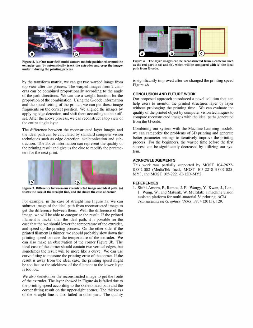
Figure 2. (a) Our near-field multi-camera module positioned around theextruder can (b) automatically track the extruder and crop the image-under it during the printing process.
by the transform matrix, we can get two warped image fromtop view after this process. The warped images from 2 cam-eras can be combined proportionally according to the angleof the path directions. We can use a weight function for theproportion of the combination. Using the G-code informationand the speed setting of the printer, we can put those imagefragments on the correct position. We aligned the images byapplying edge detection, and shift them according to their off-set. After the above process, we can reconstruct a top view ofthe entire single layer.
The difference between the reconstructed layer images andthe ideal path can be calculated by standard computer visiontechniques such as edge detection, skeletonization and sub-traction. The above information can represent the quality ofthe printing result and give us the clue to modify the parame-ters for the next print.
Figure 3. Difference between our recontructed image and ideal path. (a)shows the case of the straight line, and (b) shows the case of corner
For example, in the case of straight line Figure 3a, we cansubtract image of the ideal path from reconstructed image toget the difference between them. With the difference of theimage, we will be able to categorize the result. If the printedfilament is thicker than the ideal path, it is possible for thecase that the we should lower the temperature of the extruder,and speed up the printing process. On the other side, if theprinted filament is thinner, we should probably slow down theprinting speed or raise the temperature of the extruder. Wecan also make an observation of the corner Figure 3b. Theideal case of the corner should contain two vertical edges, butsometimes the result will be more like a curve. We can usecurve fitting to measure the printing error of the corner. If theresult is away from the ideal case, the printing speed mightbe too fast or the stickiness of the filament to the lower layeris too low.
We also skeletonize the reconstructed image to get the routeof the extruder. The layer showed in Figure 4a is failed due tothe printing speed according to the skeletonized path and thecorner fitting result on the upper-right corner. The thicknessof the straight line is also failed in other part. The quality
Figure 4. The layer images can be reconstructed from 2 cameras suchas the red part in (a) and (b), which will be compared with (c) the idealpath from G-code.
is significantly improved after we changed the printing speedFigure 4b.
CONCLUSION AND FUTURE WORKOur proposed approach introduced a novel solution that canhelp users to monitor the printed structures layer by layerwithout prolonging the printing time. We can evaluate thequality of the printed object by computer vision techniques tocompare reconstructed images with the ideal paths generatedfrom the G-code.
Combining our system with the Machine Learning models,we can categorize the problems of 3D printing and generatebetter parameter settings to iteratively improve the printingprocess. For the beginners, the wasted time before the firstsuccess can be significantly decreased by utilizing our sys-tem.
ACKNOWLEDGEMENTSThis work was partially supported by MOST 104-2622-8-002-002 (MediaTek Inc.), MOST 103-2218-E-002-025-MY3, and MOST 105-2221-E-12D-MY2.
REFERENCES1. Sitthi-Amorn, P., Ramos, J. E., Wangy, Y., Kwan, J., Lan,
J., Wang, W., and Matusik, W. Multifab: a machine visionassisted platform for multi-material 3d printing. ACMTransactions on Graphics (TOG) 34, 4 (2015), 129.


![A Heuristic Scaling Strategy for Multi- Robot Cooperative 3D Printing · 2019-09-10 · well as multi-material layers 3D printing [14, 15] and, binder jetting [16]. While these processes](https://img.pdfslide.us/doc/110x75/5eddf54fad6a402d66693413/a-heuristic-scaling-strategy-for-multi-robot-cooperative-3d-printing-2019-09-10.jpg)


![The 3D printing ‘revolution’ · 3D printing ‘Bigger than internet’ FT 21.6.12 3D printing: ‘The PC all over again?’ Economist 1.12.12 ‘3D printing [..] has the potential](https://img.pdfslide.us/doc/110x75/5f08eac77e708231d42459a8/the-3d-printing-arevolutiona-3d-printing-abigger-than-interneta-ft-21612.jpg)