Embed Size (px)
Citation preview
Abstract—In this paper, a novel ear identification system for
security applications is presented. The structure of human ear is
an inimitable characteristic that remains comparatively
unchanged with time. The consistent and stout features of ear
can be extracted from a distance. The proposed system consists
of three modules that are database module, image processing
module and identification module. The system takes ear images
and extracts useful information by image processing module.
The resultant information and templates are stored in data base.
The suspect’s image after processing by image processing
module is sent to identification module for assessment with the
record present in database using template matching. Then the
identification module makes decision regarding similarity or
difference between the processed images. Finally, the decision is
sent to report generator component that generates the final
report. The system has been tested for 24 ear images by using
templates. The results show that the system is 98% accurate.
Index Terms—Database module, ear identification, image
processing module, security applications, template matching.
I. INTRODUCTION
Ear-base identification is one of the emerging biometric
techniques for security applications. This identification
method is very useful in small towns and remote areas where
robbery is very common and increasing day by day. In
majority of robberies, the criminals wear a cap, wrap and a
cloth hanging from the cap to their face thus cover up their
faces. However, the ears of the criminal remain detectable.
On this base, the criminals can be identified. In general, it is
predicted that the ear shape of any person is unique and
distinctive. Although, humans cannot discriminate other
people on the basis of their ears, but an ear identification
system can identify, extract and differentiate between the
inimitable features of ears. Basically the human ears can only
be used in automated and programmed identification with
reliability. Ear identification is more consistent as compared
to face recognition. The inconsistency in face recognition is
due to its appearance, direction and aging effects. The
location of ear on head side makes the identification process
easy and simple.In 1949, Alfred Iannarelli was the first one
who used ear features to recognize people. He physically
calculated the distances between various parts of ear and
Manuscript received August 20, 2012; revised October 10, 2012.
Shahzadi Tayyaba, Nitin Afzulpurkar, and Akhtar Husain are with the
School of Engineering and Technology, Asian Institute of Technology (AIT),
Bangkok, Thailand (e-mail: [email protected]).
Muhammad Waseem Ashraf and Muhammad Imran are with the
Department of Physics (Electronics), GC University Lahore Pakistan (e-mail:
Aneela Noreen is with the UET Lahore, Pakistan (e-mail:
studies about 10,000 ear samples to demonstrate the
inimitability of human ears [1]. Reference [2] used a method
to identify the region of ear from a 3D image. They used two
step algorithm with model template structure and online
recognition. Reference [3] developed an ear recognition
system by fusing SIFT features of color segmented slice
regions of an ear. Reference [4] reported kernel independent
component analysis (KICA) and support vector machine
(SVM) with Gaussian radial basis function (GRBF) for ear
feature extraction and classification. Reference [5] used a
model based scheme for ear feature extraction. Reference [6]
used wavelets transform for ear recognition and results
achieved were up to 94.3 %. Reference [7] used a multimodal
biometric system for recognition of human faces and ears by
means of Eigen faces and Eigen ears. Reference [8]
developed two 3D ear detection systems by structure from
motion (SFM) and shape from shading (SFS) methods. By
interpolation of edge and ravine, they performed
segmentation of the ear section. Reference [9] reported a
study of ear biometrics by using various methods like Eigen
ear, principle components analysis (PCA), Hausdorff
matching and ICP matching .Ear images were mapped to
energy field by applying feature extraction using force field
[10]. The wavelet approach was developed by using the log
Gabor filter [11]. Reference [12] used the feature level fusion
technique for ear biometric system. The process of template
matching computes the degree of similarity between two
images. One image is called template image and second is
called the input image. Various algorithms and methods have
been used for template matching. Reference [13] reported a
template matching algorithm. The exact Legendre moment
invariants were employed by cross-correlation for image
recognition.
In this research work, the authors present a novel ear
identification system for security applications. The proposed
system consists of three modules that are database module,
image processing module and identification module. The
system extracts valuable information and removes noise from
the processed images to improve the accuracy of the results.
Testing has been performed to show the accuracy and the
efficiency of the ear identification system. The system has
been tested for 24 ear images by using template matching
process. Experimental results show that the system is highly
accurate and robust. This system is easily applicable in the
police stations at the remote areas.
II. SYSTEM DESCRIPTION
The ear identification system consists of three modules
that are database module, image processing module and
identification module as shown in Fig. 1.
A Novel Ear Identification System for Security
Applications
S. Tayyaba, M. W. Ashraf, N. Afzulpurkar, A. Hussain, M. Imran, and A. Noreen
International Journal of Computer and Communication Engineering, Vol. 2, No. 2, March 2013
125
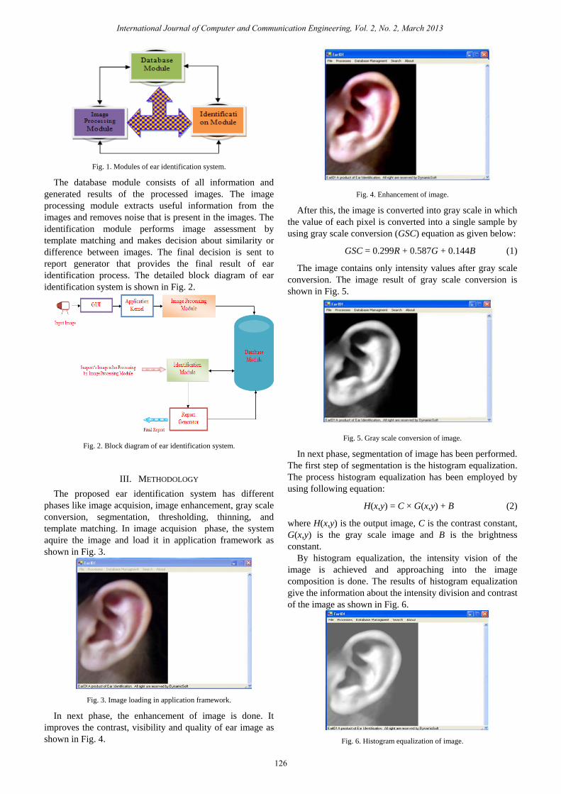
Fig. 1. Modules of ear identification system.
The database module consists of all information and
generated results of the processed images. The image
processing module extracts useful information from the
images and removes noise that is present in the images. The
identification module performs image assessment by
template matching and makes decision about similarity or
difference between images. The final decision is sent to
report generator that provides the final result of ear
identification process. The detailed block diagram of ear
identification system is shown in Fig. 2.
Fig. 2. Block diagram of ear identification system.
III. METHODOLOGY
The proposed ear identification system has different
phases like image acquision, image enhancement, gray scale
conversion, segmentation, thresholding, thinning, and
template matching. In image acquision phase, the system
aquire the image and load it in application framework as
shown in Fig. 3.
Fig. 3. Image loading in application framework.
In next phase, the enhancement of image is done. It
improves the contrast, visibility and quality of ear image as
shown in Fig. 4.
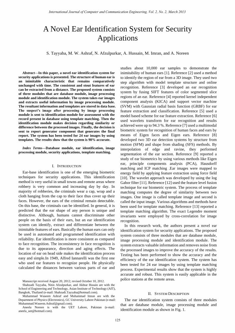
Fig. 4. Enhancement of image.
After this, the image is converted into gray scale in which
the value of each pixel is converted into a single sample by
using gray scale conversion (GSC) equation as given below:
GSC = 0.299R + 0.587G + 0.144B (1)
The image contains only intensity values after gray scale
conversion. The image result of gray scale conversion is
shown in Fig. 5.
Fig. 5. Gray scale conversion of image.
In next phase, segmentation of image has been performed.
The first step of segmentation is the histogram equalization.
The process histogram equalization has been employed by
using following equation:
H(x,y) = C × G(x,y) + B (2)
where H(x,y) is the output image, C is the contrast constant,
G(x,y) is the gray scale image and B is the brightness
constant.
By histogram equalization, the intensity vision of the
image is achieved and approaching into the image
composition is done. The results of histogram equalization
give the information about the intensity division and contrast
of the image as shown in Fig. 6.
Fig. 6. Histogram equalization of image.
International Journal of Computer and Communication Engineering, Vol. 2, No. 2, March 2013
126
Most of the information present in an image is hold by the
edges. Edges give information about the object position,
shape and size. The image result of edge detection is shown
in Fig. 7.
Fig. 7. Edge detection of image.
The thresholding of image has been used along with edge
detection to accentuate the edges of images. The resultant
image after applying thresholding is shown in Fig. 8.
Fig. 8. Image thresholding.
After thresholding, thinning has been applied on the
resultant image. The process of thinning converts the dark
points into white with the length of pattern edges and results
into thin lines. Thinning has removed the selected foreground
pixels from the image by applying following equation [14]:
Thin(A) = A ∩ ¬ H-M(A) (3)
where A represents the input image, and H-M is the hit and
miss function.
The resultant image after thinning has been shown in Fig.
9.
Fig. 9. Image result of thinning.
After thinnning, template matching has been performed
using the equation of correlation as shown below [15]:
0 0
( , ) ( , ) ( , )N M
t
s t
R x y F s t A x s y t
(4)
where R(x,y) is the output image, Fl(s,t) is the template and A
represents input image (suspect’s image).
The output value of template matching operation will be
highest at those pixel points where the image arrangement
matches with the template. Here the large values of image are
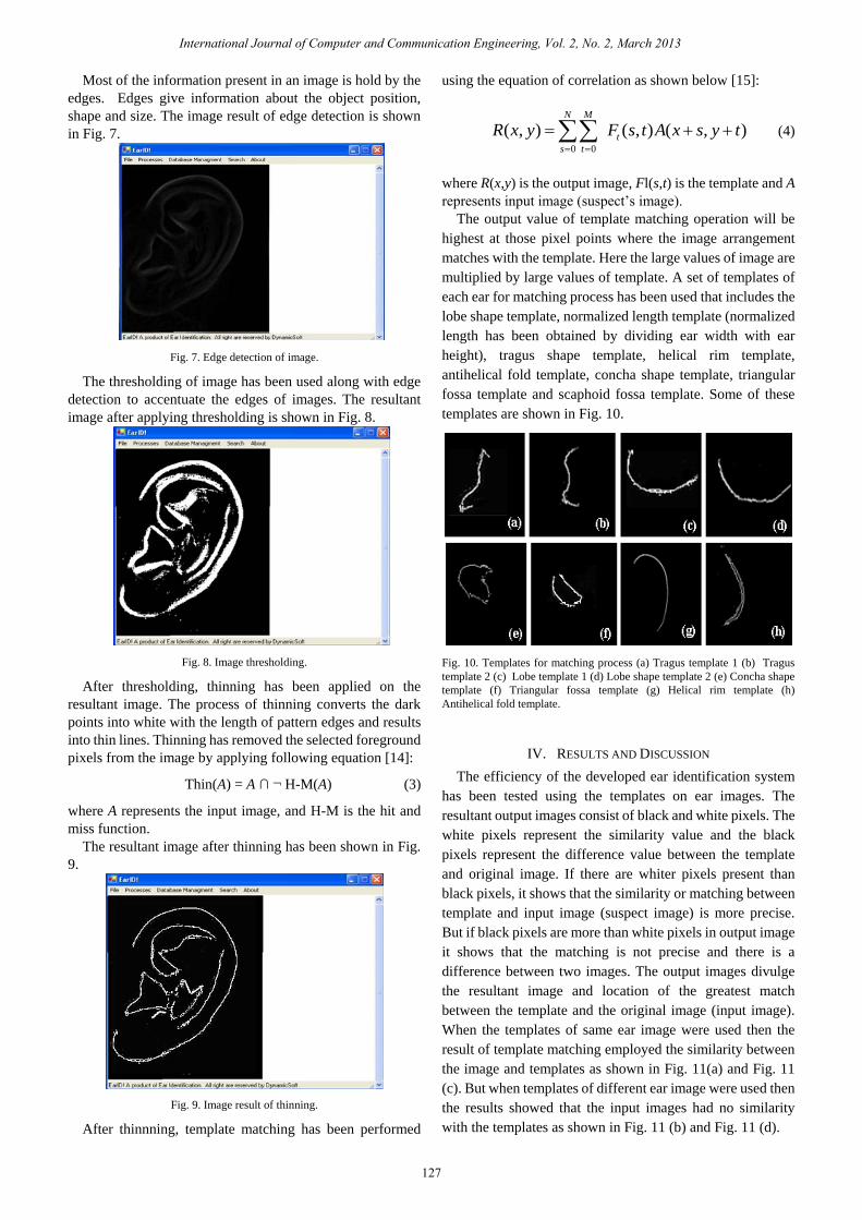
multiplied by large values of template. A set of templates of
each ear for matching process has been used that includes the
lobe shape template, normalized length template (normalized
length has been obtained by dividing ear width with ear
height), tragus shape template, helical rim template,
antihelical fold template, concha shape template, triangular
fossa template and scaphoid fossa template. Some of these
templates are shown in Fig. 10.
Fig. 10. Templates for matching process (a) Tragus template 1 (b) Tragus
template 2 (c) Lobe template 1 (d) Lobe shape template 2 (e) Concha shape
template (f) Triangular fossa template (g) Helical rim template (h)
Antihelical fold template.
IV. RESULTS AND DISCUSSION
The efficiency of the developed ear identification system
has been tested using the templates on ear images. The
resultant output images consist of black and white pixels. The
white pixels represent the similarity value and the black
pixels represent the difference value between the template
and original image. If there are whiter pixels present than
black pixels, it shows that the similarity or matching between
template and input image (suspect image) is more precise.
But if black pixels are more than white pixels in output image
it shows that the matching is not precise and there is a
difference between two images. The output images divulge
the resultant image and location of the greatest match
between the template and the original image (input image).
When the templates of same ear image were used then the
result of template matching employed the similarity between
the image and templates as shown in Fig. 11(a) and Fig. 11
(c). But when templates of different ear image were used then
the results showed that the input images had no similarity
with the templates as shown in Fig. 11 (b) and Fig. 11 (d).
International Journal of Computer and Communication Engineering, Vol. 2, No. 2, March 2013
127
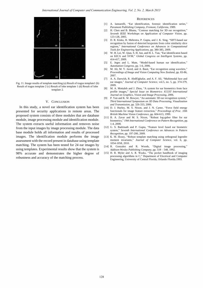
Fig. 11. Image results of template matching (a) Result of tragus template1 (b)
Result of tragus template 2 (c) Result of lobe template 1 (d) Result of lobe
template 2.
V. CONCLUSION
In this study, a novel ear identification system has been
presented for security applications in remote areas. The
proposed system consists of three modules that are database
module, image processing module and identification module.
The system extracts useful information and removes noise
from the input images by image processing module. The data
base module holds all information and results of processed
images. The identification module performs the image
assessment with the record present in database using template
matching. The system has been tested for 24 ear images by
using templates. Experimental results show that the system is
98% accurate and demonstrates the higher degree of
robustness and accuracy of the matching process.
REFERENCES
[1] A. Iannarelli, “Ear identification, forensic identification series,”
Paramont Publishing Company, Fremont, California, 1989.
[2] H. Chen and B. Bhanu, “Contour matching for 3D ear recognition,”
Seventh IEEE Workshops on Application of Computer Vision, pp.
123-128, 2005.
[3] D. R. Kisku, H. Mehrotra, P. Gupta, and J. K. Sing, “SIFT-based ear
recognition by fusion of detected keypoints from color similarity slice
regions,” International Conference on Advances in Computational
Tools for Engineering Applications, pp. 380-385, 2009.
[4] W. H. Lei, W. Qian, S. H. Jun, and H. L. Yan, “Ear identificaton based
on KICA and SVM,” Global Congress on Intelligent Systems, pp.
414-417, 2009.
[5] E. Jeges and L. Mate, “Model-based human ear identification,”
Automation Congress, pp. 1-6, 2006.
[6] M. Ali, M. Y. Javed, and A. Basit, “Ear recognition using wavelets,”
Proceedings of Image and Vision Computing New Zealand, pp. 83-86,
2007.
[7] A. A. Darwish, R. AbdElghafar, and A. F. Ali, “Multimodal face and
ear images,” Journal of Computer Science, vol.5, no. 5, pp. 374-379,
2009.
[8] M. A. Mottaleb and J. Zhou, “A system for ear biometrics from face
profile images,” Special Issue on Biometrics: ICGST International
Journal on Graphics, Vision and Image Processing, 2006.
[9] P. Yan and K. W. Bowyer, “An automatic 3D ear recognition system,”
Third International Symposium on 3D Data Processing, Visualization
and Transmission, pp. 326-333, 2006.
[10] D. J. Hurley, M. S. Nixon, and J. N. Carter, “Force field energy
functionals for image feature extraction,” Proceedings of Proc. 10th
British Machine Vision Conference, pp. 604-613, 1999.
[11] B. A. Zavar and M. S. Nixon, “Robust log-gabor filter for ear
biometrics,” 19th International Conference on Pattern Recognition, pp.
1-4, 2008.
[12] G. S. Badrinath and P. Gupta, “Feature level fused ear biometric
system,” Seventh International Conference on Advances in Pattern
Recognition, pp. 197-200, 2009.
[13] K. M. Hosny, “Robust template matching using orthogonal legendre
moment invariants,” Journal of Computer Science, vol. 6, pp.
1054-1058, 2010.
[14] R. Gonzalez and R. Woods, “Digital image processing,”
Addison-Wesley Publishing Company, pp. 518 – 548, 1992.
[15] H. R. Myler and A. R. Weeks, “The pocket handbook of imaging
processing algorithms in C,” Department of Electrical and Computer
Engineering, University of Central Florida, Orlando Florida.1993.
International Journal of Computer and Communication Engineering, Vol. 2, No. 2, March 2013
128