Embed Size (px)
Citation preview

7/24/2019 A Novel Double-Stator Double-Rotor Brushless Electrical Continuously Variable Transmission System
http://slidepdf.com/reader/full/a-novel-double-stator-double-rotor-brushless-electrical-continuously-variable 1/4
IEEE TRANSACTIONS ON MAGNETICS, VOL. 49, NO. 7, JULY 2013 3909
A Novel Double-Stator Double-Rotor Brushless Electrical Continuously
Variable Transmission System
Shuangxia Niu, S. L. Ho, and W. N. Fu
The Hong Kong Polytechnic University, Hung Hom, Kowloon, Hong Kong
A novel double-stator, double-rotor brushless electrical continuously variable transmission (E-CVT) system is proposed. This machineincorporates an inner stator which can fully utilize the space inside the inner rotor so as to reduce the volume of the machine. Thisdesign is based on magnetic flux modulating and magnetic gear effect to make the E-CVT system work in different operating modes.Different control modes of this proposed machine are also discussed and analyzed, including pure electric mode, hybrid mode, andbattery charging mode. Time-stepping finite element method (TS-FEM) is used to analyze the dynamic performance of the machine.TS-FEM simulation results are reported to verify the validity of the proposed design.
Index Terms— Electric machine, electrical continuously variable transmission, finite element method, vernier machine.
I. I NTRODUCTION
BECAUSE of concerns of energy crisis and environmental
sustainability, hybrid electric vehicles (HEVs), which is acompromise of gasoline vehicles and pure electric vehicles, are
attracting much interests among researchers around the world.
The most prominent merit of HEVs is their fuel economy and
energy ef ficiency, most of which is by virtue of their highly ef fi-
cient power-split systems. HEV system uses electrical continu-
ously variable transmission (E-CVT) system for power splitting
in order to realize energy allocation, reduce the fuel consump-
tion and improve the energy ef ficiency of the whole system [1].
A wealth of E-CVT systems have been designed, developed
and applied in HEVs. For the Toyota Prius, its E-CVT propul-
sion system comprises of a planetary gear set and two elec-
tric motors/generators. Through inverters, the electromechan-
ical power flows ef ficiently among the engine, the motor/gener-ators (M/Gs) and the battery. The power in the internal combus-
tion engine (ICE) and electric machines can be effectively split
and combined together [2]. However, in that E-CVT system,
the planetary gear, which is a key element of the system, is a
mechanical device which has inevitable mechanical problems
such as frictional loss, high maintenance and audible noise. To
solve this problem, a series of gearless E-CVT propulsion sys-
tems are developed. The key is to use a double-rotor machine
to replace the mechanical gear to realize the power split and
combination [3]. At present, induction machine and permanent
magnet (PM) machine based double-rotor integrated E-CVT
propulsion systems have been developed. Although these de-
signs can effectively alleviate the mechanical problems and im-
prove the system ef ficiency, they require carbon brushes and slip
rings which reduce the reliability of the system. In order to elim-
inate the brushes, a new gearless and brushless E-CVT propul-
sion system using a double-stator PM brushless machine has
been developed [4]. Even though that design requires no carbon
brush and slip ring, an additional induction machine has to be
Manuscript received October 28, 2012; revised January 04, 2013, January 18,2013, andJanuary31, 2013; accepted February 14,2013. Date of current versionJuly 15, 2013. Corresponding author: S. Niu (e-mail: [email protected]).
Color versions of one or more of the figures in this paper are available onlineat http://ieeexplore.ieee.org.
Digital Object Identifier 10.1109/TMAG.2013.2248347
cascaded with the PM unit to realize the power split. The main
drawback of that machine is bulkiness.
In recent years, magnetic gear system is emerging as a re-
placement of planetary gears to realize contactless transmissionof torque and speed [5]. In [6], a coaxial magnetic gear inte-
grated E-CVT system with a compact structure and improved
torque density has been studied. However, the complicated
structure of the machine which involves four airgaps and
three rotating parts are basically impractical. In [7], a compact
E-CVT system with two rotors and one stator is presented.
Since two sets of stator windings are housed inside one set of
slots in the stator, the outside diameter of machine needs to be
enlarged. In that design the secondary winding of the machine
and one rotor constitute a mutlipole PM machine. However,
the main demerit of that structure is the additional loss because
the rotor is mechanically connected to the ICE, not directly to
wheels of the vehicle.In this paper, based on magnetic gear effects, a novel E-CVT
system with two mechanical ports and two electrical ports is
proposed. The core component of this system is a brushless
double-stator double-rotor electric machine and the electrical
power transmission is totally contactless. There is no mechan-
ical problem arising from brushes in this design when compared
with the conventional ones. In essence, this is a fully magneti-
cally and electrically integrated design and the structure is com-
pact and its torque density is high. The shortcomings of the
machine in [7] are overcomed. The working principle of this
machine is described and the different control modes of this
system are also introduced. The performance including the static
and dynamic operations of the system is analyzed using a cir-cuit-field-motion coupled time-stepping finite element method
(CFM-TS-FEM).
II. SYSTEM CONFIGURATION AND WORKING PRINCIPLE
A. E-CVT System
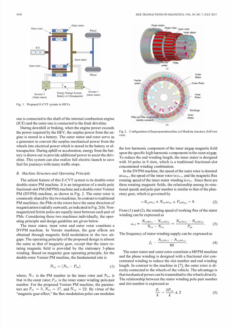
Fig. 1 shows the configuration of the proposed E-CVT
system. The core of the system consists of a brushless
double-stator, double-rotor PM machine, two inverters and
an energy storage system (battery or ultracapacitor). These
inverters are connected to the inner and outer stator windings
with the energy storage system. As for the rotors, the inner
0018-9464/$31.00 © 2013 IEEE
7/24/2019 A Novel Double-Stator Double-Rotor Brushless Electrical Continuously Variable Transmission System
http://slidepdf.com/reader/full/a-novel-double-stator-double-rotor-brushless-electrical-continuously-variable 2/4
3910 IEEE TRANSACTIONS ON MAGNETICS, VOL. 49, NO. 7, JULY 2013
Fig. 1. Proposed E-CVT system in HEVs.
one is connected to the shaft of the internal combustion engine
(ICE) and the outer one is connected to the final driveline.
During downhill or braking, when the engine power exceeds
the power required by the HEV, the surplus power from the en-
gine is stored in a battery. The outer stator and rotor serve as
a generator to convert the surplus mechanical power from the
wheels into electrical power which is stored in the battery or ul-
tracapacitor. During uphill or acceleration, energy from the bat-
tery is drawn out to provide additional power to assist the driv-
eline. This system can also realize full electric launch to save
fuel for journeys with many traf fic stops.
B. Machine Structure and Operating Principle
The salient feature of this E-CVT system is its double-rotor
double-stator PM machine. It is an integration of a multi-pole
fractional-slot PM (MFPM) machine and a double-rotor Vernier
PM (DVPM) machine, as shown in Fig. 2. The outer rotor is
commonly shared by the two machines. In contrast to traditional
PM machines, the PMs in the rotors have the same direction of
magnetization (radially outward), as indicated in Fig. 2(b). Non-
magnetized ferrite poles are equally inset between each pair of
PMs. Considering these two machines individually, the oper-
ating principle and design guideline are given below.
The inner stator, inner rotor and outer rotor constitute a
DVPM machine. In Vernier machines, the gear effects areobtained through magnetic field modulation in the two air-
gaps. The operating principle of the proposed design is almost
the same as that of magnetic gear, except that the inner ro-
tating magnetic field is provided by the stationary 3-phase
winding. Based on magnetic gear operating principle, for the
double-rotor Vernier PM machine, the fundamental rule is
(1)
where; is the PM number in the inner rotor and is
that in the outer rotor; is the inner stator winding pole-pair
number. For the proposed Vernier PM machine, the parame-
ters are , , and . By virtue of the
“magnetic gear effect,” the flux-modulation poles can modulate
Fig.2. Configuration of theproposedmachine.(a) Machine structure. (b)Frontview.
the low harmonic component of the inner airgap magnetic field
upon the specific high harmonic components in the outer airgap.
To reduce the end winding length, the inner stator is designed
with 10 poles in 9 slots, which is a traditional fractional-slot
concentrated winding combination.
In the DVPM machine, the speed of the outer rotor is denotedas , the speed of the inner rotor is , and the magnetic flux
rotating speed of the inner stator winding is . Since there are
three rotating magnetic fields, the relationship among its rota-
tional speeds and pole-pair number is similar to that of the plan-
etary gear, which is governed by
(2)
From (1) and (2), the rotating speed of working flux of the stator
winding can be expressed as
(3)
The frequency of stator winding supply can be expressed as
(4)
The outer stator and outer rotor constitute a MFPM machine
and the phase winding is designed with a fractional slot con-
centrated winding to reduce the slot number and end winding
length. In contrast to the machine in [7], the outer rotor is di-
rectly connected to the wheels of the vehicle. The advantage is
that mechanical power can be transmitted to the wheels directly.
The relationship between the stator winding pole-pair number
and slot number is expressed as
(5)
7/24/2019 A Novel Double-Stator Double-Rotor Brushless Electrical Continuously Variable Transmission System
http://slidepdf.com/reader/full/a-novel-double-stator-double-rotor-brushless-electrical-continuously-variable 3/4
NIU et al.: A NOVEL DOUBLE-STATOR DOUBLE-ROTOR BRUSHLESS ELECTRICAL CONTINUOUSLY VARIABLE TRANSMISSION SYSTEM 3911
where, is the stator slot number and is the winding
pole-pair number. In this proposed machine, the outer stator pa-
rameters are , and is the largest common
divisor of and .
The advantages of the proposed structure of this double-rotor
double-stator brushless PM machine are summarized as the fol-
lowing:
1) Compact structure The compact structure can fully utilizethe limited space within the outer rotor. The volume of the
unit is reduced and the torque density is improved.
2) Flexible controllability The inner DVPM machine with
two rotating parts can be controlled in a manner similar to
that for planetary gear. The outer PM machine may serve
as either a generator to return energy to the battery or work
as a motor to assist the ICE to drive the driveline.
3) Short end winding Compared with conventional stator
windings, the “concentrated winding” structure can ef-
fectively reduce the end winding length to reduce copper
losses.
4) Magnetic gear effect Flux modulation caused by magneticgear effect in the machine can reduce the rated speed of the
machine while producing a relatively high torque.
III. A NALYSIS AND POTENTIAL APPLICATIONS
A. CFM-TS-FEM
A two-dimensional (2-D) CFM-TS-FEM coupling with elec-
tric circuit equations is used to simulate the operation of the
motor. The basic equations of transient magnetic field-circuit
coupled problem can be summarized as [8]
(6)
(7)
where; is the depth of the model in the -direction (axial di-
rection); is the symmetry multiplier; is the reluctivity of ma-
terial; is the conductivity; is the -component of the mag-
netic vector potential; is the polarity ( 1 or 1) to repre-
sent, respectively, the forward paths or return paths; is the
total cross-sectional area of the region occupied by the winding
in the solution domain; is the total conductor number of this
winding; is the number of parallel branches in the winding;, and are, respectively, the d.c. resistance, branch cur-
rent and branch voltage of the winding.
B. FEM Analysis Results
Using CFM-TS-FEM, the steady-state and transient perfor-
mance of the machine is analyzed. Fig. 3 depicts the back-emf
waveforms induced in the inner and outer stator windings with
an outer rotor speed of 545.5 rpm and an inner rotor speed of
444.4 rpm. The electrical degree of inner stator is referred to
5 pole pairs and that of outer stator is referred to 22 pole pairs.
The frequencies of outer and inner windings are 50 and 100 Hz,
respectively. Simulation results agree well with the description
given in Section II. The two sets of stator windings are con-
nected independently and each can be flexibly controlled by in-
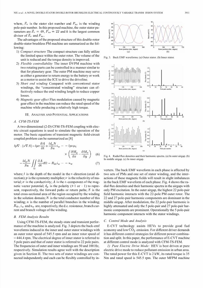
Fig. 3. Back EMF waveforms. (a) Outer stator. (b) Inner stator.
Fig. 4. Radial flux densities and their harmonic spectra. (a) In outer airgap. (b)In middle airgap. (c) In inner airgap.
verters. The back EMF waveform in each phase is affected by
two sets of PMs and one set of stator winding, and the inter-
actions of these magnetic fields will result in slight imbalances
in the back EMF waveform of each phase. Fig. 4 shows the ra-
dial flux densities and their harmonic spectra in the airgaps with
only PM excitation. In the outer airgap, the highest 22 pole-pair
field harmonic interacts with the 22-pole PM outer rotor. The
22 and 27 pole-pair harmonic components are dominant in the
middle airgap. After modulation, the 22 pole-pair harmonic ishighly attenuated and only the 5 pole-pair and 27 pole-pair har-
monic components are prominent. Operationally the 5 pole-pair
harmonic component interacts with the stator windings.
C. Control Mode and Analysis
E-CVT technology assists HEVs to provide good fuel
economy and low emission. For different driver demands
it has different control strategies for different power combina-
tion and split. In this paper, the performance of E-CVT machine
at different control mode is analyzed with CFM-TS-FEM.
1) Pure Electric Drive Mode: HEV is best driven at pure
electric drive mode to reduce pollutant emission in urban area.
The rated power for this E-CVT is 2 kW, its rated torque is 35
Nm and rated speed is 545.5 rpm. The outer MFPM machine

7/24/2019 A Novel Double-Stator Double-Rotor Brushless Electrical Continuously Variable Transmission System
http://slidepdf.com/reader/full/a-novel-double-stator-double-rotor-brushless-electrical-continuously-variable 4/4
3912 IEEE TRANSACTIONS ON MAGNETICS, VOL. 49, NO. 7, JULY 2013
Fig. 5. Torque waveforms during pure electric mode.
Fig. 6. Torque output versus phase current in pure electric mode.
serves as a motor to convert the electric power from battery
to mechanical output at the wheels. When the outer rotor runs
at 545.5 rpm, and there is no mechanical power from ICE, the
torque waveform on the outer rotor is around 35 Nm, as shown
in Fig. 5. The relationship between stator current and torque
output on the outer rotor is given in Fig. 6.2) Hybrid Drive Mode: During starting up or climbing, the
power demand for the traction driver is high, hence power from
the battery should augment the mechanical energy from ICE to
drive the wheels. For this machine, the inner DVPM machine
should be assisting, and coordinated with, the outer MFPM ma-
chine to drive the outer rotor. To drive the outer rotor at 545.5
rpm, the outer winding needs to be fed with a current of 200
Hz and, assuming the inner rotor speed is 222.2 rpm, the inner
winding should be fed with a current at 100 Hz. The torque
output on outer rotor and the torque input to inner rotor are
given in Fig. 7. Torque input from ICE is around 22 Nm and
torque output from the outer rotor is 53 Nm when the vehicle
is climbing. Cogging torque is approximately related to the in-verse of the smallest common multiple of the PM pole number
and stator slot number. Here, the outer PM pole number is 22,
slot number is 48, so the torque ripple is small. With 27 PM
poles and 9 slots in the inner stator, the torque ripple is however
larger. Skewing of the slots is necessary to reduce the torque
ripples.
3) Battery Charging Mode: During regenerative braking,
downhill or idling time, the mechanical energy at the wheels
or ICE is converted to electric energy and stored in the bat-
tery. With inner and outer rotor rotating at different speeds, the
Fig. 7. Torque waveforms during hybrid operating mode.
induced voltages in the inner and outer stator windings are as
shown in Fig. 3. Through the inverter, this energy can be used
to charge the battery or ultracapacitors for further uses.
IV. CONCLUSION
A novel double-stator double-rotor E-CVT system utilizing
magnetic gear effect to modulate the magnetic flux has been pro-
posed to realize different E-CVT operating modes. The salient
advantage of the design is that two rotors and two stators are
incorporated within one machine frame and one inner stator is
housed within the space inside the inner rotor. The structure is
compact. TS-FEM is used to analyze the performance of the
machine, verify its working principle and its validity in prac-
tical applications.
ACKNOWLEDGMENT
This work was supported by the Research Grant Councilof the Hong Kong SAR Government under projects PolyU
5176/09E and 4–ZZBM
R EFERENCES
[1] Y. Wang, M. Cheng, and K. T. Chau, “Review of electronic-conti-nously variable transmission propulsion system for full hybrid electricvehicles,” J. Asian Electr. Veh., vol. 7, no. 2, Dec. 2009.
[2] S. Sasaki, “Toyota’s newly-developed hybrid powertrain,” in Proc. Int.
Symp. Power Semicond. Dev. & ICs, 1998, pp. 17–22.[3] M. J. Hoeijmakers and J. A. Ferreira, “The electric variable transmis-
sion,” IEEE T. Ind. Appl., vol. 42, no. 4, pp. 1092–1100, 2006.[4] Y. Wang, M. Cheng, Y. Fan, and K. T. Chau, “A double-stator perma-
nent magnet brushless machine system for electric variable transmis-sion in hybrid electric vehicles,” in Proc. 2010 IEEE Vehicle Power
Propulsion Conf. (VPPC), Sept. 1–3, 2010, pp. 1–5.[5] K. Atallah, S. Calverley, and D. Howe, “Design, analysis and realiza-
tion of a high-performance magnetic gear,” IEE Proc. Electric Power
Appl., vol. 151, no. 2, pp. 135–143, 2004.[6] L. Jian and K. T. Chau, “Design and analysis of a magnetic-geared
electronic-continuously variable transmission system using finite ele-ment method,” Progress In Electromagn. Res., vol. 107, p. 15, 2010.
[7] S. Niu, S. L. Ho, and W. N. Fu, “Design of a novel electrical continu-ously variable transmission system based on harmonic spectra analysisof magnetic field,” IEEE Trans. Magn., accepted for publication.
[8] W. N. Fu, P. Zhou, D. Lin, S. Stanton, and Z. J. Cendes, “Modeling of solid conductors in two-dimensional transient finite-element analysisand its application to electric machines,” IEEE Trans. Magn., vol. 40,no. 2, pp. 426–434, Mar. 2004.