Embed Size (px)
Citation preview

A NOVEL CONTINUOUS-FLOW REACTOR USING
A REACTIVE DISTILLATION TECHNIQUE FOR
BIODIESEL PRODUCTION
Final Report KLK340 N06-02
National Institute for Advanced Transportation Technology University of Idaho
Brian He
December 2006
DISCLAIMER
The contents of this report reflect the views of the authors,
who are responsible for the facts and the accuracy of the
information presented herein. This document is disseminated
under the sponsorship of the Department of Transportation,
University Transportation Centers Program, in the interest of
information exchange. The U.S. Government assumes no
liability for the contents or use thereof.

1. Report No. 2. Government Accession No. 3. Recipient’s Catalog No.
5. Report Date
December 2006
4. Title and Subtitle
A Novel Continuous-Flow Reactor Using Reactive Distillation Technique for
Economical Biodiesel Production
6. Performing Organization Code
KLK340
5.Author(s)
Brian He 8. Performing Organization Report No.
N06-02
9. Performing Organization Name and Address
National Institute for Advanced Transportation Technology
University of Idaho
10. Work Unit No. (TRAIS)
PO Box 440901; 115 Engineering Physics Building
Moscow, ID 838440901
11. Contract or Grant No.
DTRS98-G-0027
12. Sponsoring Agency Name and Address
US Department of Transportation
Research and Special Programs Administration
13. Type of Report and Period Covered
Final Report: Sept. 2004-Dec. 2006
400 7th Street SW
Washington, DC 20509-0001
14. Sponsoring Agency Code
USDOT/RSPA/DIR-1
Supplementary Notes:
16. Abstract
Biodiesel is a fuel comprised of mono-alkyl esters of long-chain fatty acids produced from vegetable oils through a
transesterification process. In existing continuous-flow biodiesel production processes, 100 percent excess alcohol is typically
used in order to drive the reaction to completion. The excess alcohol must be recovered in a separate process, which involves
additional operating and energy costs. In the first stage of this study, a novel reactor system using a manufactured (glass) reactive
distillation (RD) column was developed and studied. The concept to dramatically reduce the use of excess alcohol and still
produce a quality fuel was proven. The next step, and the focus of this part of the study, was to scale-up the system to a
production rate of 80 to 100 ml/min and measure its effectiveness. A 20 sieve-tray RD reactor system was designed by the author
and fabricated at the University of Idaho machine shop. This model was used to produce biodiesel and product parameters such
as methyl ester content and total glycerol were analyzed. Preliminary results showed that process parameters of methanol-to-oil
ratio of 4:1 (molar) and a column temperature of 65°C produced a biodiesel that was 90.71 percent converted in five minutes.
17. Key Words
Biodiesel fuels; alternative fuels;
18. Distribution Statement
Unrestricted; Document is available to the public through the National
Technical Information Service; Springfield, VT.
19. Security Classif. (of this report)
Unclassified
20. Security Classif. (of this page)
Unclassified
21. No. of Pages
14
22. Price
…
Form DOT F 1700.7 (8-72) Reproduction of completed page authorized
TABLE OF CONTENTS INTRODUCTION .......................................................................................................................... 1
MATERIALS AND METHODOLOGY........................................................................................ 4
Chemicals and Reagents ................................................................................................................. 4
Experimental Setup......................................................................................................................... 5
Experimental Procedures ................................................................................................................ 6 Feed preparation .......................................................................................................................................................6 Startup Procedures: ...................................................................................................................................................7 Steady-operation and sampling.................................................................................................................................8 Analytical Procedures ...............................................................................................................................................8
RESULTS AND DISCUSSIONS................................................................................................... 1
Injector Coking ............................................................................................................................... 5
Summary ......................................................................................................................................... 6
REFERENCES ............................................................................................................................... 8
APPENDIX..................................................................................................................................... 9
A Novel Continuous-Flow reactor Using Reactive Distillation page i Technique for Economical Biodiesel Production
INTRODUCTION
Biodiesel from seed oils has attracted increasing interests and has been shown to be the best
supplement to fossil-based fuels due to its environmental advantages and renewable resource
availability. Seed oils of rapeseed, canola, and yellow mustard have certain advantages for
biodiesel production over other vegetable oils, among them are better cold-flow properties. There
is a great demand for the commercialization of biodiesel production, which in turn calls for a
technically and economically sound reactor technology. Reactive distillation (RD) is a chemical
unit operation in which chemical reactions and separations occur simultaneously in one unit. It is
an effective alternative to the traditional combination of reactor and separation units especially
when involving in reversible reactions, such as vegetable oil transesterification, or consecutive
chemical reactions. The significant advantages of the RD over the conventional sequential
process are the high chemical conversion rate and low capital and operational cost. The
performance of a reactive distillation column is influenced by several parameters, e.g. operating
temperatures, size of reactive and separation zones, reflux ratio, feed rate and location, etc,
which were thoroughly investigated.
The ultimate goal of this research was to explore a technically and economically sound reactor
technology for economical biodiesel production. RD technique was applied to the
transesterification of seed oils including rapeseed, canola, and yellow mustard. The hypothesis
was that by employing the RD technique, biodiesel preparation and product concentration can be
accomplished in one single unit. The use of excess alcohol was greatly reduced, but a high
alcohol to oil ratio was achieved locally in the reaction zone by recycling a small quantity of
alcohol. This ensured a higher conversion of oil to biodiesel. The recovery of alcohol is
integrated into the RD reactor, which reduces capital and operating costs. Combining this lower
alcohol requirement with elevated operating temperature, the RD technique significantly
shortened the reaction time from that of conventional processes and greatly increased the
productivity.
A Novel Continuous-Flow reactor Using Reactive Distillation page 1 Technique for Economical Biodiesel Production

Figure 1. Illustration of biodiesel production from seed oils.
The excess alcohol in conventional systems remains unreacted and is contained in the crude
biodiesel and the glycerol by-product streams. It has to be recovered and purified for reuse
through rectification and distillation, which are energy-consuming processes. In the RD process,
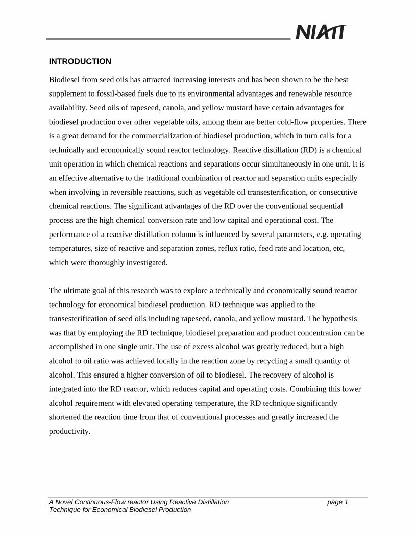
chemical reaction and product separation occur simultaneously in one unit (Fig. 2 and 3). The
RD reactor consists of perforated plates. Each plate holds certain amount of reacting liquid,
forming a sequential mini-reactor series. Unreacted alcohol is vaporized from the reboiler, flows
upward constantly, and bubbles through the liquid on each plate, which provides uniform
mixing. The thru-vapor is condensed at the top of the RD column and refluxes partially back to
the top of the column and the rest combines with the feeding stream. It is this portion of the
recycled alcohol that creates a local excess alcohol to ensure the reactions in the mini-reactors to
a completion. Therefore, the excess alcohol needed at the input stream is considerably reduced.
Combining with elevated operating temperature, the RD technique significantly shortens the
reaction from that of conventional process and greatly increases the productivity.
A Novel Continuous-Flow reactor Using Reactive Distillation page 2 Technique for Economical Biodiesel Production
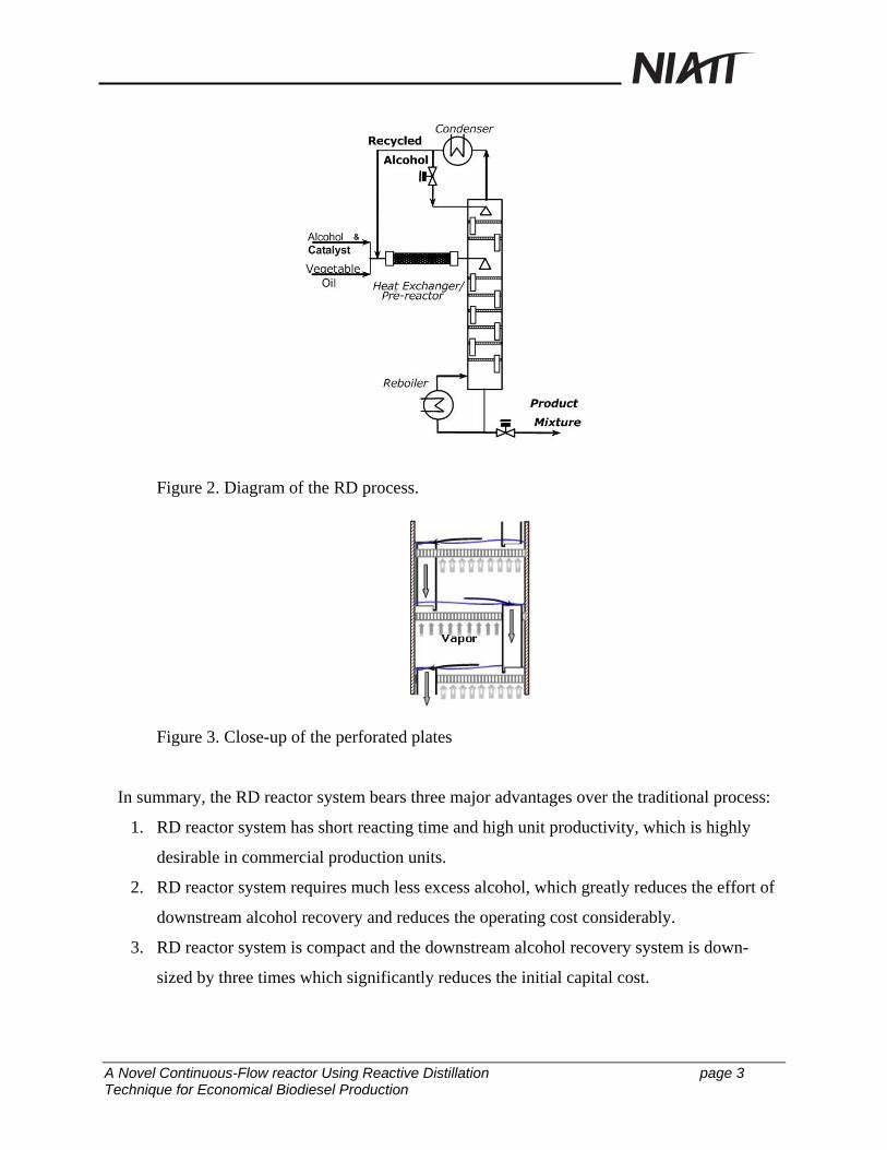
Figure 2. Diagram of the RD process.
Figure 3. Close-up of the perforated plates
In summary, the RD reactor system bears three major advantages over the traditional process:
1. RD reactor system has short reacting time and high unit productivity, which is highly
desirable in commercial production units.
2. RD reactor system requires much less excess alcohol, which greatly reduces the effort of
downstream alcohol recovery and reduces the operating cost considerably.
3. RD reactor system is compact and the downstream alcohol recovery system is down-
sized by three times which significantly reduces the initial capital cost.
A Novel Continuous-Flow reactor Using Reactive Distillation page 3 Technique for Economical Biodiesel Production
MATERIALS AND METHODOLOGY
Chemicals and Reagents
Crude canola oil and methanol were used in this research as the feedstock. Potassium hydroxide
and potassium methoxide were used as catalysts. The canola oil was obtained from the oil seed
processing plant at the Department of Biological and Agricultural Engineering of the University
of Idaho (Peterson, et al., 1983). The oil was screw-pressed and filtered to remove any
particulates. No further treatments were performed on the oil. The acid value of the oil was 1.97
mg KOH/g sample. The fatty acid profile of the canola oil was analyzed using the GC method
(Hammond, 1991) (see Table 1). Methanol (analytical grade) and potassium hydroxide (A.C.S
certified, purity greater than 87.9 percent weight) were from J. T. Baker (Phillipsburg, NJ).
Potassium methoxide (32 percent w/w solution in methanol) was obtained from Degussa
Corporation, Germany. Other analytical reagents and standard chemicals of GPO-trinder
Reagent, triolien, diolien, methyl oleate, and glycerol were all analytical grade and purchased
from Sigma-Aldrich Co. (St. Louis, MO).
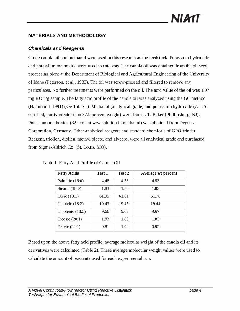
Table 1. Fatty Acid Profile of Canola Oil
Fatty Acids Test 1 Test 2 Average wt percent
Palmitic (16:0) 4.48 4.58 4.53
Stearic (18:0) 1.83 1.83 1.83
Oleic (18:1) 61.95 61.61 61.78
Linoleic (18:2) 19.43 19.45 19.44
Linolenic (18:3) 9.66 9.67 9.67
Eicosic (20:1) 1.83 1.83 1.83
Erucic (22:1) 0.81 1.02 0.92
Based upon the above fatty acid profile, average molecular weight of the canola oil and its
derivatives were calculated (Table 2). These average molecular weight values were used to
calculate the amount of reactants used for each experimental run.
A Novel Continuous-Flow reactor Using Reactive Distillation page 4 Technique for Economical Biodiesel Production

Table 2. Average Molecular weights of Canola oil and its derivatives
Triglycerides Di-glycerides Mono-glycerides Potassium
Soap
Canola
Methyl Esters
Average Mol.
Weight (g/mol) 887.30 622.22 357.16 321.17 297.07
Experimental Setup
A bench-scale continuous-flow RD system (Fig. 4) was developed and tested with optimum
process parameters obtained from laboratory scale studies. The central system component is a
stainless steel, perforated plate distilling column.
Figure 4. Bench-scale continuous-flow RD reactor unit for biodiesel production.
A Novel Continuous-Flow reactor Using Reactive Distillation page 5 Technique for Economical Biodiesel Production

Table 3. Bench-scale RD Column Details
Column Sieve tray Tray details
Actual Number of Trays 20 Hole dia. (mm) 1.20
Tray spacing (mm) 53 Plate thickness (mm) 1.22
weir height (mm) 6.5 Triangular pitch (mm) 4.00
weir pipe dia. (mm) 8.9 # of holes 98
Column dia. (mm) 50 Hole area (cm2) 1.11
Total plate area (cm2) 19.6 Liquid covered area (cm2) 17.3
Downcomer area (cm2) 0.6 Liquid volume/ tray volume 0.88
Net area (cm2) 19.0 Liquid hold-up volume (mL)/ tray 11.2
Active area (cm2) 18.4
Other major components of the bench-scale biodiesel production facility include:
• Thermo-siphon reboiler, 750 W Heating Capacity
• Overhead condenser, with reflux valve
• Pre-reactor, in-line static mixer, heat wrapped
• Feed pumps (calibration: Appendix I)
• Flow-meters (calibration: Appendix I)
• Temperature display and control unit
• Gravity based continuous glycerol-biodiesel separator
Experimental Procedures
Feed preparation
a) Oil. The feedstock was first checked for free fatty acid content according to ASTM 975 and
moisture using Karl Fischer method. Feedstock having FFA greater than3 percent or moisture
greater than1 percent should not be used directly for transesterification in the reactive distillation
column. The oil needed for experimental run was transferred to a covered container and placed
near the process area.
A Novel Continuous-Flow reactor Using Reactive Distillation page 6 Technique for Economical Biodiesel Production

b) Methanol-Catalyst Premix. The methanol (greater than 99.9 percent) and the desired base
catalyst were transferred, in desired amounts, to a three-gal container and stirred to completely
dissolve the catalyst in methanol. The amount of methanol and catalyst was determined based
upon the required methanol-to-oil ratio and catalyst concentration.
Example calculation:
Methanol-to-oil molar ratio: 4:1
Catalyst: KOCH3 (32 percent wt in methanol)
Catalyst conc.: 0.15 percent mol
Oil flow rate: 70 mL/min, or 70×0.91 = 63.7 g/min (oil density ρ = 0.91 g/mL)
Therefore, total methanol required: 4×(63.7/882.1)×32 = 9.24 (g/min)
Catalyst requirement: (63.7/882.1)×0.15×70 = 0.75 g/min
KOCH3 (32 percent) requirement: 0.75/0.32 = 2.36 g/min, or 2.36/1.2 = 1.97 mL/min
(density of KOCH3 solution 32 percentwt ρ = 0.91 g/mL)
Methanol associated with catalyst solution: 2.36×(1-0.32) = 1.60 g/min
Fresh methanol required = 9.24 - 1.60 = 7.64 g/min, or 7.64/0.79 = 9.67 mL/min
Methanol-catalyst mix ratio: 2.36/7.64×100 = 30.9 g catalyst/ 100g of methanol, or
1.97/9.67×100 = 20.4 mL of catalyst/ 100 ml of methanol
Methanol-catalyst flow rate: 2.36 + 7.64 = 10 g/min, or 1.97+9.67 = 11.64 mL/min
Startup Procedures:
At the start of each test the reactor and reboiler section were drained of all liquids before
anything was fed to the reactor. Approx. 300 ml solution, containing 200 ml of
previously prepared biodiesel and 100 ml of methanol were injected into the column. The
reboiler heater was set to 100°C and allowed to heat for approx. 30-45 minutes till the
temperature of the top tray reached 60°C.
The oil and methanol-catalyst were pumped at 50 percent rate into the top tray of the
column via pre-reactor. The calibration of pumps and flow meters (appendix 1) was used
to adjust the required flow. The pre-reactor heater was set to 55°C. After 30 minutes the
flow rates were increased to actual calculated flow rates.
A Novel Continuous-Flow reactor Using Reactive Distillation page 7 Technique for Economical Biodiesel Production

Steady-operation and sampling
At actual feed flow rates, the liquid level in the reboiler section was maintained to the flow
circulation level using the product output needle valve as a control medium. Fluctuation in the
level at the sight tube was difficult to avoid but could be maintained at an acceptable level. The
product from the reboiler was transferred to the vertical gravity settler to separate glycerol phase
from the biodiesel.
At two hour intervals, samples were collected from different sampling ports: after pre-reactor;
after reboiler, settled biodiesel and all tray-sampling ports. Approximately 6 ml of each sample
was collected in plastic centrifuge tubes containing 3 ml of 0.1N HCL to stop the reaction and
wash out the glycerol, methanol and catalyst from the ester phase. The sample tubes were gently
shaken then centrifuged.
Note: A logbook was maintained to register all major difficulties; actions and important things
happened during the operation.
Analytical Procedures
The neutralized samples collected from the reactor were centrifuged for 10 minutes at 2500 rpm.
For each sample, 1 ml of the upper phase was diluted with 9 mls of 2-propanol- hexane (5:4 v/v)
and one ml of the diluted solution was then filter into HPLC vials.
Compositions of the reaction mixtures were analyzed by using HP 1090 HPLC with ELSD
(Altech2000). Load ‘CANOLA.m’ method, which was calibrated for canola oil and its methyl
esters. The method used gradient elution with aqueous-organic and non-aqueous mobile phase
steps: 70 percent acetonitrile + 30 percent water in 0 min, 100 percent acetonitrile in 10 min, 50
percent acetonitrile + 50 percent 2-propanol- hexane (5:4 v/v) in 20 min and 7.5 min final hold
up. The column used was a C18, 7um SGX. The column temperature was maintained at 40°C
while the temperature of ELSD was kept at 60°C and the flow rate of the nebulizer gas was 1.5
l/min. The LC report was configured to provide the composition as percent TG, DG, MG and
methyl esters.
A Novel Continuous-Flow reactor Using Reactive Distillation page 8 Technique for Economical Biodiesel Production

RESULTS AND DISCUSSIONS
The feed stream flow rates for the test run were chosen carefully in order to avoid any column
flooding or weeping problems. The feed stream details and calculated liquid residence times are
tabulated in Table 4. The column was operated as per procedures discussed in section above.
Table 4. Feed Input Details
Feed Stream:
Feed Composition (%mol)
Canola Oil, % mol 20
Methanol, % mol 80
Methanol-to-Oil Ratio 4
Catalyst (KOCH3) Concentration, %mol 0.15
Total Feeding rate (g/min) 72.9
Oil Feed flow (ml/min) 70
Methanol feed flow (ml/min) 11.7
Feed temperature, degrees C 55
Feed density, g/ml 0.8948
Reactor retention time
Oil residence time per tray (min) 0.16
Total residence time (min) 1.60
A set of three readings was obtained for each sampling location with sampling time interval of 2
hours. The average results as weight percentage with respect to cumulative residence time at
each sampling location is listed in Table 5.
A Novel Continuous-Flow reactor Using Reactive Distillation page 1 Technique for Economical Biodiesel Production

Table 5. Average Results as Weight Percentage
Stage MG ME DG TG Cumulative
residence time (min)
Initial 0.00 0.00 0.00 100.00 0.00
Feed point 0.41 1.34 1.54 96.70 0.10
Tray 2 1.32 7.00 5.87 85.80 0.38
Tray 4 2.02 29.24 7.02 61.74 0.66
Tray 6 2.72 64.71 4.52 28.04 0.94
Tray 8 1.81 75.45 3.64 18.43 1.22
Tray 10 0.99 84.66 4.10 10.24 1.50
After Reboiler 1.20 90.71 1.76 6.32 4.63
It was found that most of the reaction takes place in the column with a reaction time of less than
2 min. Some portion of the reaction also takes place in the reboiler section, which has additional
3 minutes residence time. Despite of the sufficient residence in the reboiler not enough reaction
conversion was achieved, this is possibly due to 1) high reboiler temperatures keep the methanol
away from liquid phase, and 2) at high temperature the catalyst decomposes. All three sets of
data and their averages are plotted (Fig. 5 and 6) with respect to cumulative residence time. The
concentration profiles obtained on a RD column follows the same pattern as in a batch reactor
obtained by various researchers (Noureddini, et al., 1997; Darnoko, et al., 2000; Freedman, et al.,
1986).
A Novel Continuous-Flow reactor Using Reactive Distillation page 2 Technique for Economical Biodiesel Production

Methyl Ester Profile (RD)
0
20
40
60
80
100
0 1 2 3 4 5
Residence Time (min)
% M
ethy
l Est
er
(a)
Monoglycerides Profile (RD)
0.000.501.001.502.002.503.003.504.00
0.00 1.00 2.00 3.00 4.00 5.00
Residence Time (min)
% M
G
(b)
Figure 5. Concentration profiles for (a) methyl ester ,and (b) monoglycerides obtained at
different sampling locations in a bench-scale RD reactor unit.
.
A Novel Continuous-Flow reactor Using Reactive Distillation page 3 Technique for Economical Biodiesel Production

Diglycerides Profile (RD)
0.00
2.00
4.00
6.00
8.00
10.00
0.00 1.00 2.00 3.00 4.00 5.00
Residence Time (min)
% D
G
(c)
Triglycerides Profile (RD)
0.00
20.00
40.00
60.00
80.00
100.00
120.00
0.00 1.00 2.00 3.00 4.00 5.00
Residence Time (min)
%TG
(d)
Figure 6. Concentration profiles for (c) diglycerides and (d) triglycerides obtained at
different sampling locations in a bench-scale RD reactor unit.
All three sets of data follows similar pattern but the repeatability for monoglycerides and
diglycerides concentration profile was poor. Overall very good concentration profiles were
obtained from the test run on the RD reactor unit. The performance of the RD reactor was
compared with that of batch reactor operated with similar operating conditions (Fig. 7).
A Novel Continuous-Flow reactor Using Reactive Distillation page 4 Technique for Economical Biodiesel Production

Comparison of RD vs. Batch
01020
3040506070
8090
100
0.0 1.0 2.0 3.0 4.0 5.0 6.0
Reaction Time (min)
% M
E
RDbatch
Figure 7. The comparison of reactive distillation reactor technique with batch reactor for
biodiesel production via transesterification.
The comparison shows that the batch reactor had higher initial reaction rate than the RD. This
was due to the shear mixing provided in the batch reactor. This shows that the initial rate of
reaction is governed by the mass transfer limitation due to insolubility of methanol and oil phase.
This problem is overcome with the formation of methyl esters, which act as a co-solvent for both
reactants. However in RD reactor, the actual kinetics of reaction is faster than in the batch
reactor. This is due to the high temperature and higher methanol-to-oil ratio achieved inside the
column. At the end of the last reactive tray in the RD column, the ester content has reached up to
85 percent as compared to about 70 percent with batch reactor with same reaction time provided.
This shows that reactive distillation can achieve higher process yield with shorter reaction times
as compared to the conventional batch reactor technology for biodiesel production via
transesterification.
Injector Coking
A machine vision system for scoring the results of the injector coking was used to compare the
coking effect of canola methyl esters (CME) compared to that of diesel. Figure 4 shows three
pictures from the system used for evaluation. On the left is a profile of a clean injector, next to it
is the profile of an injector after 50 hours run on diesel and the third is the same type of injector
A Novel Continuous-Flow reactor Using Reactive Distillation page 5 Technique for Economical Biodiesel Production

run on CME for 50 hours. The number of pixels that make up the tip and shoulders is measured
and the area calculated. Coked injectors are measured in the same way and compared to the clean
one. The difference in area is the amount of coke built up on the injector. A coking index with
diesel set at one was developed for the comparison (Jones et al, 2001). At 50 hours the set of
three injectors was indexed, evaluated and averaged. The coking on the injectors was
approximately 1.5 times that of diesel.
Clean Diesel: 100 hours Canola Methyl Esters: 100 hours
Figure 4. Injector coking profiles.
Summary
A bench-scale RD rector for biodiesel preparation has been designed, fabricated, and tested.
Experiments have shown that the bench-scale RD process can produce biodiesel at a production
rate of about 75mL/min continuously with an alcohol-oil ratio of 4:1, which is reduced by two-
thirds comparing to that typically used in current technology. The retention time (reaction time) of
the feedstocks in the column is about 5 min compared to 60 to 180 min in existing processes used
in industry. The conversion profile of the feedstock, which was monitored at multiple locations,
clearly illustrated the progression of the reaction along the column. The RD reactor was easy to
start up, operate, and control. There were no difficulties experienced in long-term operation.
The preliminary results from this and previous stage of research have shown that RD reactor is a
very promising technology for biodiesel production. A proposal based on the results was sent to
USDA National Research Initiative competitive grant program for a pilot-scale RD reactor
testing and ranked high priority (top 13 out of 198 proposals). Unfortunately, it was not funded
last year due to the limited available funds. The PI is continuing to explore the possibilities for
external funding to further develop the RD reactor for commercial uses.
A Novel Continuous-Flow reactor Using Reactive Distillation page 6 Technique for Economical Biodiesel Production

The research group has also found a couple of new technical issues at the engineering level, i.e.,
possible ester decomposition and trace water accumulation during long-term operations of the
RD reactor. Experiments are under way to further study these issues.
A Novel Continuous-Flow reactor Using Reactive Distillation page 7 Technique for Economical Biodiesel Production

REFERENCES
Darnoko, D., and M. Cheryan. 2000. “Kinetics of Palm Oil Transesterification in a Batch
Reactor,” J. Am. Oil Chem. Soc. 77(12):1263-1267.
Freedman, B., R. Butterfield, and E. Pryde. 1986. “Transesterification Kinetics of Soybean Oil,”
J. Am. Oil Chem. Soc. 63:1375-1380.
He, B. B., A. Singh, and J. Thompson. 2006. “A Novel Continuous-Flow rReactor Using
Reactive Distillation for Biodiesel Production,” Transactions of the ASABE 49(1): 107−112.
Jones, S. T., C. L. Peterson, and J. C. Thompson. 2001. “Used Vegetable Oil Fuel Blend
Comparisons Using Injector Coking in a DI Diesel Engine,” ASAE Paper No. 016051 St.
Joseph, MI: ASAE
Noureddini, H., D. Harkey, and V. Medikonduru. 1998. “Continuous Process for the Conversion
of Vegetable Oils into Methyl Esters of Fatty Acids,” J. Am. Oil Chem. Soc. 75(12):1775-
1783
A Novel Continuous-Flow reactor Using Reactive Distillation page 8 Technique for Economical Biodiesel Production

APPENDIX
Flow Control Device Calibration Tables
I. Oil Pump and Rotameter Calibration
Rotameter
Reading
Pump
Setting
Actual Flow
ml/min
10 0 22
30 1 70
50 2 112
70 3 175
80 4 231
Oil Rotameter Calibration
y = 1.7193x1.0937
R2 = 0.9931
0
50
100
150
200
250
0 10 20 30 40 50 60 70 80 90
Rotameter Reading
Act
ual F
low
(ml/m
in)
A Novel Continuous-Flow reactor Using Reactive Distillation page 9 Technique for Economical Biodiesel Production

Oil Pump Calibration
y = 52.3x + 17.415R2 = 0.9949
0
50
100
150
200
250
0 0.5 1 1.5 2 2.5 3 3.5 4 4.5
Pump Setting
Act
ual F
low
(ml/m
in)
A Novel Continuous-Flow reactor Using Reactive Distillation page 10 Technique for Economical Biodiesel Production

II. Methanol Pump Calibration
Pump Setting Actual Flow
0 1
1 15
2 24
3 32
4 36
5 36.4
Methanol Pump Calibration
y = -1.5714x2 + 14.943x + 1.1143R2 = 0.9991
0
5
10
15
20
25
30
35
40
0 1 2 3 4 5
Pump Setting
Act
ual F
low
(ml/m
in)
6
A Novel Continuous-Flow reactor Using Reactive Distillation page 11 Technique for Economical Biodiesel Production


![ItriCorp-NRLMRY STTR N06-T037itricorp.com/docs/ideas_papers/Ensemble_Forecast... · 2016. 11. 7. · ItriCorp-NRLMRY STTR N06-T037 Ensemble Forecast Application System [EFAS] for](https://img.pdfslide.us/doc/110x75/5ff2b4cfb764835f9468d29a/itricorp-nrlmry-sttr-n06-2016-11-7-itricorp-nrlmry-sttr-n06-t037-ensemble.jpg)