Embed Size (px)
Citation preview
Iranian Journal of Electrical & Electronic Engineering, Vol. 10, No. 4, Dec. 2014 267
A Novel Compact Ultra-Wideband Antenna with Single and Double Band Rejection H. Mehrpour Bernety* and B. Zakeri*(C.A.)
Abstract: Band-notch characteristic has been of great interest recently to overcome the electromagnetic interference of Ultra-wideband systems (UWB) with other existing ones. In this paper, we present a novel microstrip-fed antenna with band rejection property appropriate for UWB applications. Band-notch characteristic has been achieved by adding a rectangular resonant element to the ground section. A prototype was fabricated and measured based upon optimal parameters. Experimental results show consistency with simulation results. Measurement results confirm that the antenna covers the UWB band and satisfies a band rejection in the frequency span of 5 GHz to 5.7 GHz to restrain it from interference with Wireless Local Area Network (WLAN). Then, to achieve better isolation, a rectangular strip is appended to the band-notch creating part of the ground section to enhance obtained VSWR up to 30 through simulation. In addition, by applying a similar technique, a dual band-notched characteristic with an average simulated VSWR of around 13.75 has been achieved for WLAN and the downlink of X band satellite communication systems with each more than 10. Features such as small size, omnidirectional pattern and perfect isolation make the antenna suitable for any UWB applications. Keywords: Band-Notch Characteristic, Radiation Pattern, Reflection Coefficient, Ultra-Wideband Antenna.
1 Introduction1 In 2002, the Federal Communications Commission (FCC) of the United States decided to allow the unlicensed commercial operation of UWB technology [1]. According to this regulation, a bandwidth of 7.5 GHz, from 3.1GHz to 10.6 GHz is allotted for UWB applications. Since then, UWB technology has received great heed as a high data rate technology, which provides many benefits such as low cost, low complexity, low power consumption and coexistence with other wireless communication systems. Indeed, the maximum data rate or capacity for the ideal band limited, Additive White Gaussian Noise channel is related to the bandwidth and signal-to-noise ratio (SNR) by Shannon-Nyquist criterion [2]. Since an antenna acts as a filter for the generated UWB signal, one particular challenge concerns the research on the development of UWB antennas which have become a topic of continued investigations in the fields of wireless communications and radar applications due to such attractive features as Iranian Journal of Electrical & Electronic Engineering, 2014. Paper first received 20 May 2013 and in revised form 7 May. 2014. * The Authors are with Department of Faculty of Electrical and Computer Engineering, Babol Noshirvani University of Technology, Babol, Iran. E-mails: [email protected] and [email protected].
transmitting and receiving electromagnetic energy in shorter duration and avoiding both frequency and space dispersion. Hence, to realize UWB radio systems and signaling, UWB antennas are required.
Among various types of planar UWB antennas in the literature, microstrip line or Coplanar Waveguide (CPW) fed antennas are the most demanding candidates for UWB applications. To obtain wider bandwidth, several bandwidth enhancement techniques have been studied [3-8]. In [3], a circular disk monopole half ground antenna line is proposed. In [4], an impedance bandwidth is improved by adding slit on one side of the planar microstrip-fed antenna and adding two-step staircase notch in the ground plane. In [5], the proposed antenna consists of a truncated ground plane and two-tapered radiating patch separated by a slot of different slopes to provide a wideband bandwidth. In [6], a bandwidth enhancing technique using a modified ground plane with diagonal edges, rectangular slot, and T-shape cut was introduced. In [7], the antenna is composed of a trapezoidal slot on the ground plane, a rectangular patch in the center of the slot and three via holes connecting the rectangular patch and the microstrip feed-line. In [8], a π-shaped ground plane was used to increase bandwidth.
268 Iranian Journal of Electrical & Electronic Engineering, Vol. 10, No. 4, Dec. 2014
In order to avoid the interference with the existed WLAN, a band-stop filter should be employed in the ultra-wideband systems. So, the system will be getting larger and more complex. Instead, to overcome this potential interference, several band-notched UWB antennas have been proposed. To satisfy this notch, usual techniques include cutting proper slots such as U-shaped slot [9], C-shaped slot [10], semi-circular slot ring [11], arc-shaped slot [12], V-shaped slot [13], T-shaped slot [14] and open-ended slot [15]. Another way is to put parasitic elements, which can be considered as a filter to reject the un-required bands [10, 16-18].
In this paper, we propose a novel microstrip-fed UWB antenna with band-notch characteristic. The antenna rejects the band allocated for WLAN systems via the rectangular part added to the ground section. The notched band can also be displaced only by changing the width and length of this part independently of any other parameters and consequently with no change in pattern. Then, a novel idea is applied to the antenna to increase the VSWR of the rejected band through simulations. This approach has also led us to double band-notch characteristics. Simpler design, smaller size and more stability of the radiation pattern, and better interference rejection than the mentioned antennas are other intriguing features of our proposed antenna.
This paper includes two major sections. Section 2 is devoted to the UWB antenna design and its properties. Section 3 describes the band-notch characteristics of the antenna in detail and provides a parametric study to analyze the performance of the antenna. At the end of this section, section 3.3, measurement results of the single band-notched design is presented. Section 4 is dedicated to further discussion on the VSWR improvement of the single band-notched antenna for better isolation and the achieved double band-notched design. Although these results are obtained through simulations, the fabrication and measurement of the improved designs are considered as our future work. 2 UWB Antenna Design
2.1 Geometry Initially, a UWB antenna was designed. The top and
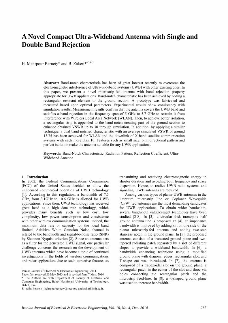
bottom view of the proposed UWB antenna is shown in Fig. 1. It is in the x-y plane (W1 along x-axis and L1 along y-axis). As illustrated, the antenna contains a tapered microstrip line, two radiating circular patches, and a defected ground structure. The width (W2) of the feeding microstrip line is set to have 50 Ω impedance. The parameters of the UWB antenna are shown in Table 1. The substrate chosen here is TACONIC TLC-30. Its thickness is 1.58 mm, the relative permittivity (εr) is 3 and the metal cladding thickness is 35 μm.
2.2 Simulation Results of VSWR and Gain The proposed antenna is simulated by CST
Microwave Studio commercial software and by using Transient Solver.
Table 1 The parameters of the antenna.
Parameter Size (mm) Parameter Size (mm) W1 24 L1 20 W2 4 L2 2.5 W3 2.4 L3 7.5 W4 6 L4 0.5 W5 3.3 L5 5 W6 0.5 L6 1 W7 12 L7 8 W8 0.4 L8 1.4 R1 2.8 R2 2.8 R3 3.8
Fig. 1 Antenna Layout (a) Top View and (b) Bottom View.
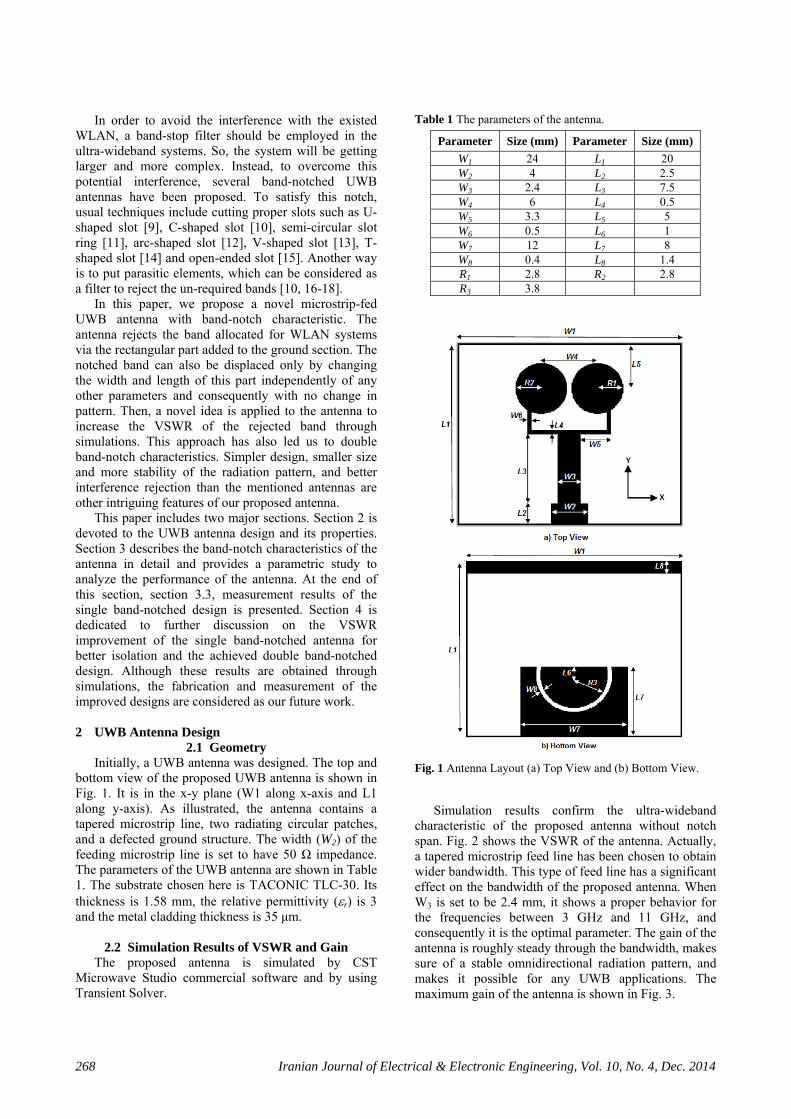
Simulation results confirm the ultra-wideband characteristic of the proposed antenna without notch span. Fig. 2 shows the VSWR of the antenna. Actually, a tapered microstrip feed line has been chosen to obtain wider bandwidth. This type of feed line has a significant effect on the bandwidth of the proposed antenna. When W3 is set to be 2.4 mm, it shows a proper behavior for the frequencies between 3 GHz and 11 GHz, and consequently it is the optimal parameter. The gain of the antenna is roughly steady through the bandwidth, makes sure of a stable omnidirectional radiation pattern, and makes it possible for any UWB applications. The maximum gain of the antenna is shown in Fig. 3.
Mehrpour Bernety & Zakeri: A Novel Compact Ultra-Wideband Antenna with Single and Double Band Rejection 269
Fig. 2 VSWR of the antenna.
Fig. 3 Maximum gain of the antenna. 3 Band-Notched UWB Antenna Design
3.1 Antenna Configuration Band-notched characteristic is presented by
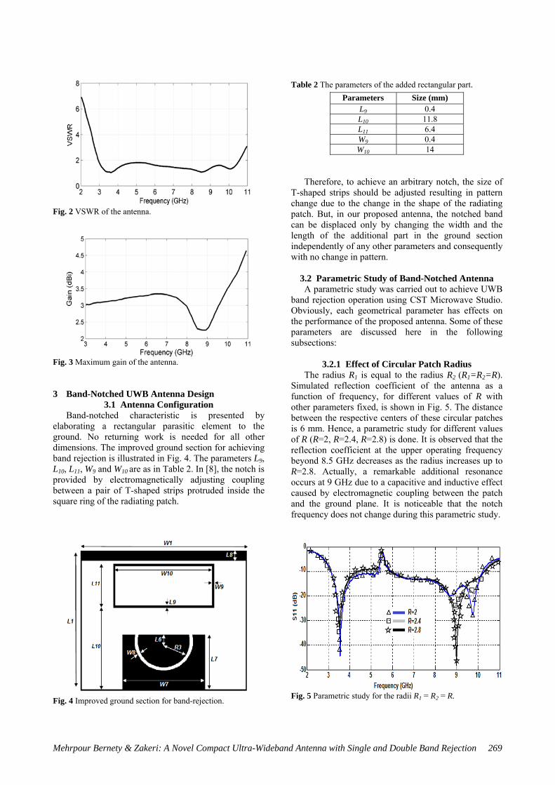
elaborating a rectangular parasitic element to the ground. No returning work is needed for all other dimensions. The improved ground section for achieving band rejection is illustrated in Fig. 4. The parameters L9, L10, L11, W9 and W10 are as in Table 2. In [8], the notch is provided by electromagnetically adjusting coupling between a pair of T-shaped strips protruded inside the square ring of the radiating patch.
Table 2 The parameters of the added rectangular part. Parameters Size (mm)
L9 0.4 L10 11.8 L11 6.4 W9 0.4 W10 14
Therefore, to achieve an arbitrary notch, the size of T-shaped strips should be adjusted resulting in pattern change due to the change in the shape of the radiating patch. But, in our proposed antenna, the notched band can be displaced only by changing the width and the length of the additional part in the ground section independently of any other parameters and consequently with no change in pattern.
3.2 Parametric Study of Band-Notched Antenna A parametric study was carried out to achieve UWB
band rejection operation using CST Microwave Studio. Obviously, each geometrical parameter has effects on the performance of the proposed antenna. Some of these parameters are discussed here in the following subsections:
3.2.1 Effect of Circular Patch Radius The radius R1 is equal to the radius R2 (R1=R2=R).
Simulated reflection coefficient of the antenna as a function of frequency, for different values of R with other parameters fixed, is shown in Fig. 5. The distance between the respective centers of these circular patches is 6 mm. Hence, a parametric study for different values of R (R=2, R=2.4, R=2.8) is done. It is observed that the reflection coefficient at the upper operating frequency beyond 8.5 GHz decreases as the radius increases up to R=2.8. Actually, a remarkable additional resonance occurs at 9 GHz due to a capacitive and inductive effect caused by electromagnetic coupling between the patch and the ground plane. It is noticeable that the notch frequency does not change during this parametric study.
Fig. 5 Parametric study for the radii R1 = R2 = R.
Fig. 4 Improved ground section for band-rejection.
270 Iranian Journal of Electrical & Electronic Engineering, Vol. 10, No. 4, Dec. 2014
Fig. 6 Parametric study for L8.
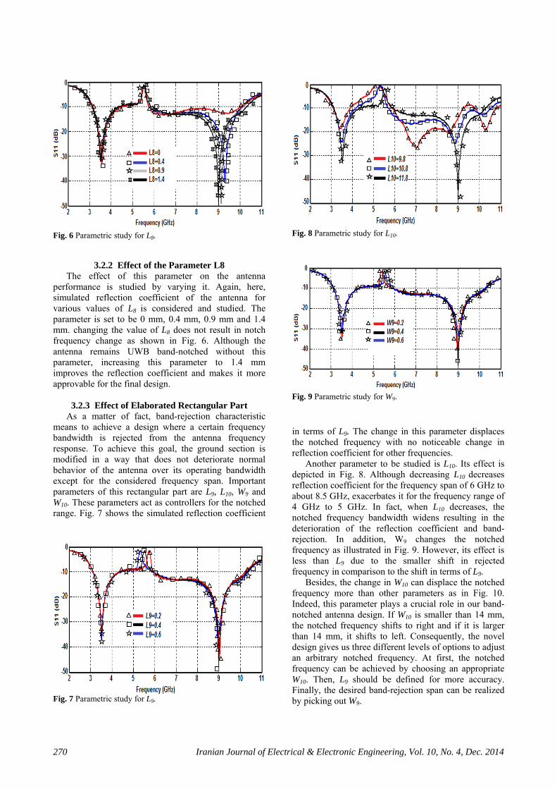
3.2.2 Effect of the Parameter L8 The effect of this parameter on the antenna
performance is studied by varying it. Again, here, simulated reflection coefficient of the antenna for various values of L8 is considered and studied. The parameter is set to be 0 mm, 0.4 mm, 0.9 mm and 1.4 mm. changing the value of L8 does not result in notch frequency change as shown in Fig. 6. Although the antenna remains UWB band-notched without this parameter, increasing this parameter to 1.4 mm improves the reflection coefficient and makes it more approvable for the final design.
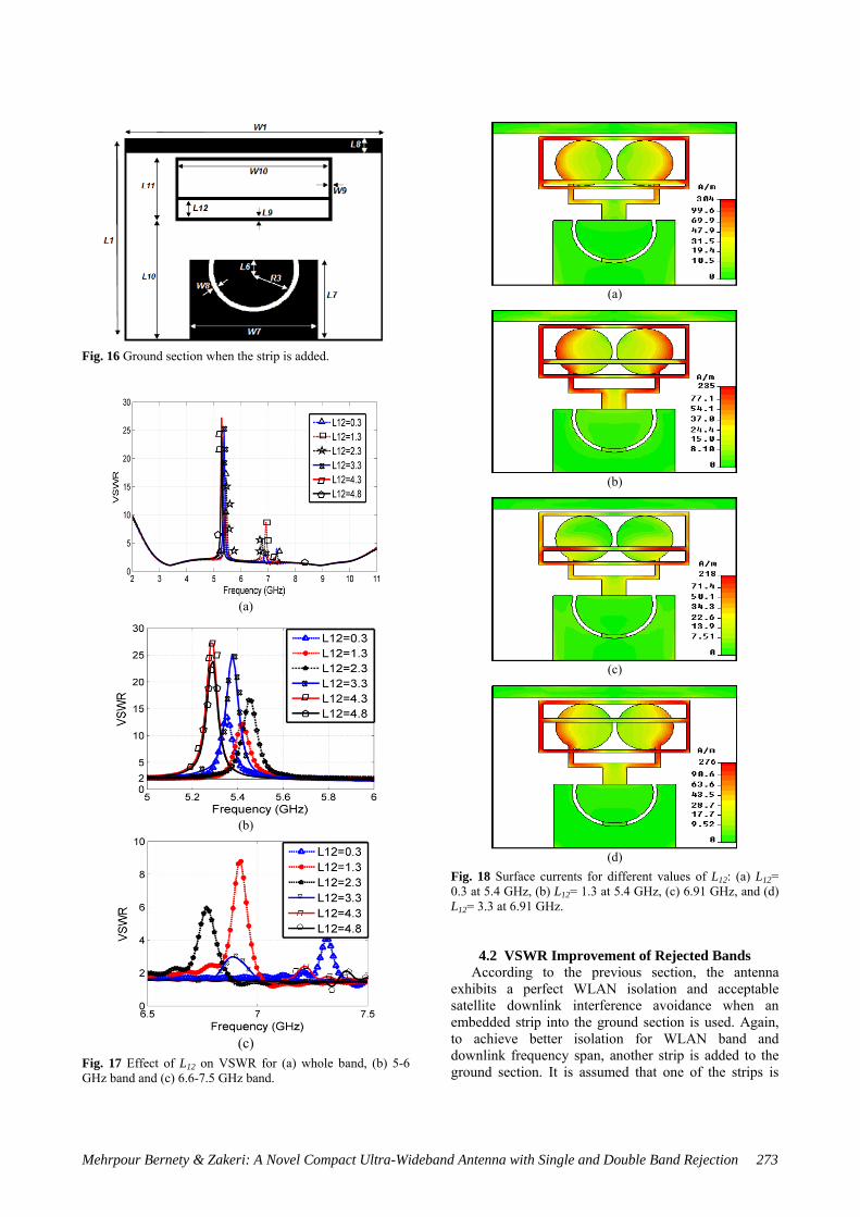
3.2.3 Effect of Elaborated Rectangular Part As a matter of fact, band-rejection characteristic
means to achieve a design where a certain frequency bandwidth is rejected from the antenna frequency response. To achieve this goal, the ground section is modified in a way that does not deteriorate normal behavior of the antenna over its operating bandwidth except for the considered frequency span. Important parameters of this rectangular part are L9, L10, W9 and W10. These parameters act as controllers for the notched range. Fig. 7 shows the simulated reflection coefficient
in terms of L9. The change in this parameter displaces the notched frequency with no noticeable change in reflection coefficient for other frequencies.
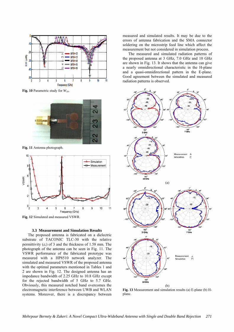
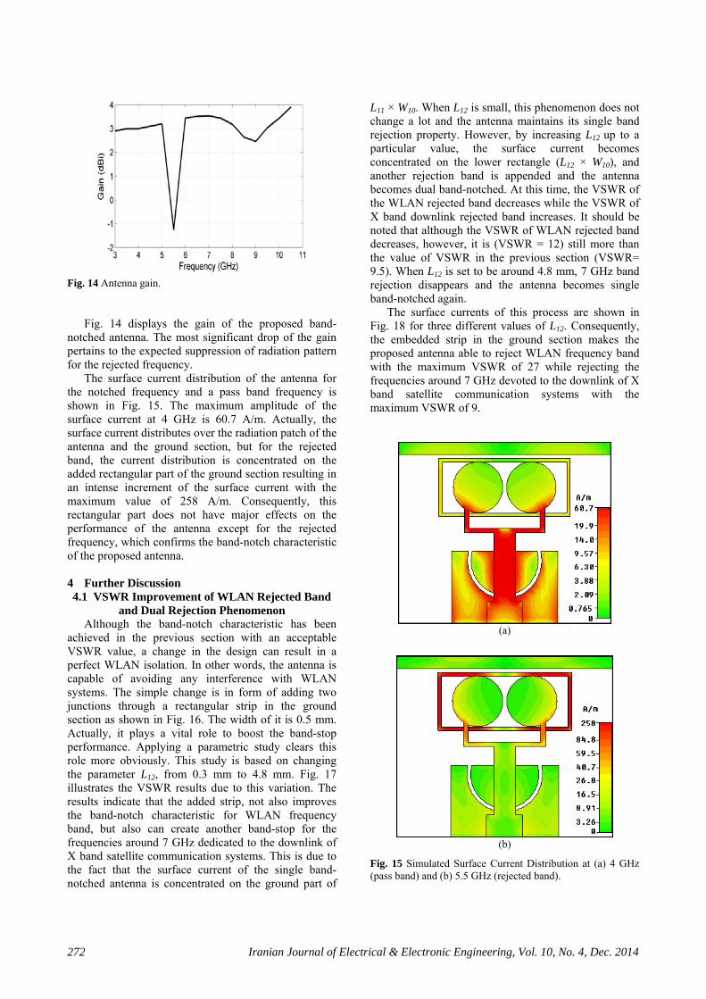
Another parameter to be studied is L10. Its effect is depicted in Fig. 8. Although decreasing L10 decreases reflection coefficient for the frequency span of 6 GHz to about 8.5 GHz, exacerbates it for the frequency range of 4 GHz to 5 GHz. In fact, when L10 decreases, the notched frequency bandwidth widens resulting in the deterioration of the reflection coefficient and band-rejection. In addition, W9 changes the notched frequency as illustrated in Fig. 9. However, its effect is less than L9 due to the smaller shift in rejected frequency in comparison to the shift in terms of L9.
Besides, the change in W10 can displace the notched frequency more than other parameters as in Fig. 10. Indeed, this parameter plays a crucial role in our band-notched antenna design. If W10 is smaller than 14 mm, the notched frequency shifts to right and if it is larger than 14 mm, it shifts to left. Consequently, the novel design gives us three different levels of options to adjust an arbitrary notched frequency. At first, the notched frequency can be achieved by choosing an appropriate W10. Then, L9 should be defined for more accuracy. Finally, the desired band-rejection span can be realized by picking out W9.
Fig. 7 Parametric study for L9.
Fig. 8 Parametric study for L10.
Fig. 9 Parametric study for W9.
Mehrpour Bernety & Zakeri: A Novel Compact Ultra-Wideband Antenna with Single and Double Band Rejection 271
Fig. 10 Parametric study for W10.
Fig. 11 Antenna photograph.
Fig. 12 Simulated and measured VSWR.
3.3 Measurement and Simulation Results The proposed antenna is fabricated on a dielectric
substrate of TACONIC TLC-30 with the relative permittivity (εr) of 3 and the thickness of 1.58 mm. The photograph of the antenna can be seen in Fig. 11. The VSWR performance of the fabricated prototype was measured with a HP8510 network analyzer. The simulated and measured VSWR of the proposed antenna with the optimal parameters mentioned in Tables 1 and 2 are shown in Fig. 12. The designed antenna has an impedance bandwidth of 2.25 GHz to 10.8 GHz except for the rejected bandwidth of 5 GHz to 5.7 GHz. Obviously, this measured notched band overcomes the electromagnetic interference between UWB and WLAN systems. Moreover, there is a discrepancy between
measured and simulated results. It may be due to the errors of antenna fabrication and the SMA connector soldering on the microstrip feed line which affect the measurement but not considered in simulation process.
The measured and simulated radiation patterns of the proposed antenna at 3 GHz, 7.0 GHz and 10 GHz are shown in Fig. 13. It shows that the antenna can give a nearly omnidirectional characteristic in the H-plane and a quasi-omnidirectional pattern in the E-plane. Good agreement between the simulated and measured radiation patterns is observed.
(a)
(b)
Fig. 13 Measurement and simulation results (a) E-plane (b) H-plane.
272 Iranian Journal of Electrical & Electronic Engineering, Vol. 10, No. 4, Dec. 2014
Fig. 14 Antenna gain.
Fig. 14 displays the gain of the proposed band-notched antenna. The most significant drop of the gain pertains to the expected suppression of radiation pattern for the rejected frequency.
The surface current distribution of the antenna for the notched frequency and a pass band frequency is shown in Fig. 15. The maximum amplitude of the surface current at 4 GHz is 60.7 A/m. Actually, the surface current distributes over the radiation patch of the antenna and the ground section, but for the rejected band, the current distribution is concentrated on the added rectangular part of the ground section resulting in an intense increment of the surface current with the maximum value of 258 A/m. Consequently, this rectangular part does not have major effects on the performance of the antenna except for the rejected frequency, which confirms the band-notch characteristic of the proposed antenna. 4 Further Discussion 4.1 VSWR Improvement of WLAN Rejected Band
and Dual Rejection Phenomenon Although the band-notch characteristic has been
achieved in the previous section with an acceptable VSWR value, a change in the design can result in a perfect WLAN isolation. In other words, the antenna is capable of avoiding any interference with WLAN systems. The simple change is in form of adding two junctions through a rectangular strip in the ground section as shown in Fig. 16. The width of it is 0.5 mm. Actually, it plays a vital role to boost the band-stop performance. Applying a parametric study clears this role more obviously. This study is based on changing the parameter L12, from 0.3 mm to 4.8 mm. Fig. 17 illustrates the VSWR results due to this variation. The results indicate that the added strip, not also improves the band-notch characteristic for WLAN frequency band, but also can create another band-stop for the frequencies around 7 GHz dedicated to the downlink of X band satellite communication systems. This is due to the fact that the surface current of the single band-notched antenna is concentrated on the ground part of
L11 × W10. When L12 is small, this phenomenon does not change a lot and the antenna maintains its single band rejection property. However, by increasing L12 up to a particular value, the surface current becomes concentrated on the lower rectangle (L12 × W10), and another rejection band is appended and the antenna becomes dual band-notched. At this time, the VSWR of the WLAN rejected band decreases while the VSWR of X band downlink rejected band increases. It should be noted that although the VSWR of WLAN rejected band decreases, however, it is (VSWR = 12) still more than the value of VSWR in the previous section (VSWR= 9.5). When L12 is set to be around 4.8 mm, 7 GHz band rejection disappears and the antenna becomes single band-notched again.
The surface currents of this process are shown in Fig. 18 for three different values of L12. Consequently, the embedded strip in the ground section makes the proposed antenna able to reject WLAN frequency band with the maximum VSWR of 27 while rejecting the frequencies around 7 GHz devoted to the downlink of X band satellite communication systems with the maximum VSWR of 9.
(a)
(b)
Fig. 15 Simulated Surface Current Distribution at (a) 4 GHz (pass band) and (b) 5.5 GHz (rejected band).
Mehrpour Bernety & Zakeri: A Novel Compact Ultra-Wideband Antenna with Single and Double Band Rejection 273
Fig. 16 Ground section when the strip is added.
(a)
(b)
(c)
Fig. 17 Effect of L12 on VSWR for (a) whole band, (b) 5-6 GHz band and (c) 6.6-7.5 GHz band.
(a)
(b)
(c)
(d)
Fig. 18 Surface currents for different values of L12: (a) L12= 0.3 at 5.4 GHz, (b) L12= 1.3 at 5.4 GHz, (c) 6.91 GHz, and (d) L12= 3.3 at 6.91 GHz.
4.2 VSWR Improvement of Rejected Bands According to the previous section, the antenna
exhibits a perfect WLAN isolation and acceptable satellite downlink interference avoidance when an embedded strip into the ground section is used. Again, to achieve better isolation for WLAN band and downlink frequency span, another strip is added to the ground section. It is assumed that one of the strips is
274 Iranian Journal of Electrical & Electronic Engineering, Vol. 10, No. 4, Dec. 2014
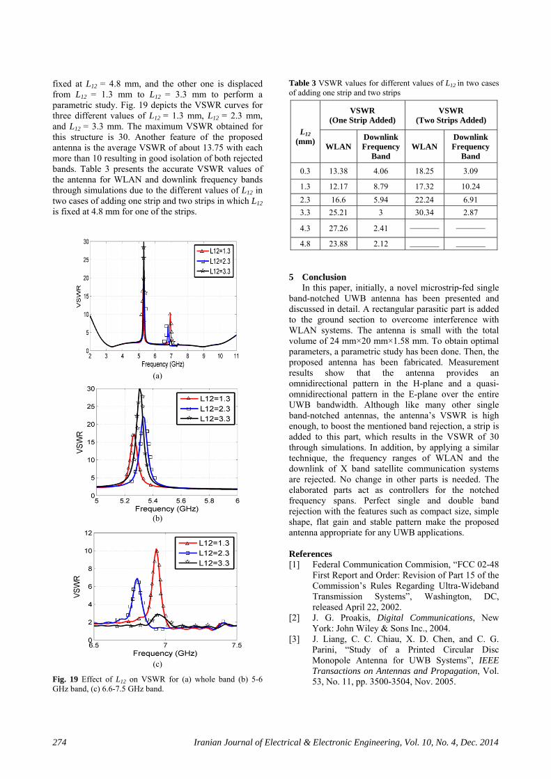
fixed at L12 = 4.8 mm, and the other one is displaced from L12 = 1.3 mm to L12 = 3.3 mm to perform a parametric study. Fig. 19 depicts the VSWR curves for three different values of L12 = 1.3 mm, L12 = 2.3 mm, and L12 = 3.3 mm. The maximum VSWR obtained for this structure is 30. Another feature of the proposed antenna is the average VSWR of about 13.75 with each more than 10 resulting in good isolation of both rejected bands. Table 3 presents the accurate VSWR values of the antenna for WLAN and downlink frequency bands through simulations due to the different values of L12 in two cases of adding one strip and two strips in which L12 is fixed at 4.8 mm for one of the strips.
(a)
(b)
(c)
Fig. 19 Effect of L12 on VSWR for (a) whole band (b) 5-6 GHz band, (c) 6.6-7.5 GHz band.
Table 3 VSWR values for different values of L12 in two cases of adding one strip and two strips
L12
(mm)
VSWR (One Strip Added)
VSWR (Two Strips Added)
WLAN Downlink Frequency
Band WLAN
Downlink Frequency
Band
0.3 13.38 4.06 18.25 3.09
1.3 12.17 8.79 17.32 10.24 2.3 16.6 5.94 22.24 6.91 3.3 25.21 3 30.34 2.87
4.3 27.26 2.41 _______ _______
4.8 23.88 2.12 _______ _______ 5 Conclusion
In this paper, initially, a novel microstrip-fed single band-notched UWB antenna has been presented and discussed in detail. A rectangular parasitic part is added to the ground section to overcome interference with WLAN systems. The antenna is small with the total volume of 24 mm×20 mm×1.58 mm. To obtain optimal parameters, a parametric study has been done. Then, the proposed antenna has been fabricated. Measurement results show that the antenna provides an omnidirectional pattern in the H-plane and a quasi-omnidirectional pattern in the E-plane over the entire UWB bandwidth. Although like many other single band-notched antennas, the antenna’s VSWR is high enough, to boost the mentioned band rejection, a strip is added to this part, which results in the VSWR of 30 through simulations. In addition, by applying a similar technique, the frequency ranges of WLAN and the downlink of X band satellite communication systems are rejected. No change in other parts is needed. The elaborated parts act as controllers for the notched frequency spans. Perfect single and double band rejection with the features such as compact size, simple shape, flat gain and stable pattern make the proposed antenna appropriate for any UWB applications. References [1] Federal Communication Commision, “FCC 02-48
First Report and Order: Revision of Part 15 of the Commission’s Rules Regarding Ultra-Wideband Transmission Systems”, Washington, DC, released April 22, 2002.
[2] J. G. Proakis, Digital Communications, New York: John Wiley & Sons Inc., 2004.
[3] J. Liang, C. C. Chiau, X. D. Chen, and C. G. Parini, “Study of a Printed Circular Disc Monopole Antenna for UWB Systems”, IEEE Transactions on Antennas and Propagation, Vol. 53, No. 11, pp. 3500-3504, Nov. 2005.
Mehrpour Bernety & Zakeri: A Novel Compact Ultra-Wideband Antenna with Single and Double Band Rejection 275
[4] A. A. Eldek, “Numerical Analysis of a Small Ultra-wideband Microstrip-fed Tap Monopole Antenna”, Progress in Electromagnetics Research, PIER 66, pp. 199-212, 2006.
[5] R. Zaker, Ch. Ghobadi and J. Nourinia, “A Modified Microstrip-fed Two-step Tapered Monopole Antenna for UWB AND WLAN Applications”, Progress in Electromagnetics Research, PIER 77, pp. 137-148, 2007.
[6] N. Prombutr, P. Kirawanich and P. Akkaraekthalin, “Bandwidth Enhancement of UWB Microstrip Antenna with a Modified Ground Plane”, International Journal of Microwave Science and Technology, Vol. 2009, Article ID 821515, 7 pages.
[7] D. Chen and C.-H. Cheng, “A Novel Compact Ultra-wideband (UWB) Wide Slot Antenna with via Holes”, Progress in Electromagnetics Research, Vol. 94, pp. 343-349, 2009.
[8] M. Ojaroudi, Sh. Yazdanifard, N. Ojaroudi and M. Naser-Moghaddasi, “Small Square Monopole Antenna With Enhanced Bandwidth by Using Inverted T-Shaped Slot and Conductor-Backed Plane”, IEEE Transactions on Antennas and Propagation, Vol. 59, No. 2, pp. 670-674, 2011.
[9] Y. D. Dong, W. Hong, Z. Q. Kuai and J. X. Chen, “Analysis of Planar Ultrawideband Antennas with On-ground Slot Band-notched Structures”, IEEE Transactions on Antennas and Propagation, Vol. 57, No. 7, pp. 1886-1893, 2009.
[10] C. M. Li and L. H. Ye, “Improved Dual Band-notched UWB Slot Antenna with Controllable Notched Bandwidths”, Progress in Electromagnetics Research, Vol. 115, pp. 477-493, 2011.
[11] M. A. Habib, “Ultra Wideband CPW-Fed Aperture Antenna with WLAN Band Rejection”, Progress in Electromagnetics Research, Vol. 106, pp. 17-31, 2010.
[12] R. Eshtiaghi, R. Zaker, J. Nouronia and Ghobadi C., “UWB Semi-elliptical Printed Monopole Antenna with Subband Rejection Filter”, Int. Journal of Electronics and Communications, Vol. 64, No. 2, pp. 133-141, 2010.
[13] B. Ahmadi and R. A. Faraji-Dana, “Miniaturized Monopole Antenna for Ultra-wide band Applications with Band Notch Filter”, IET Microwaves, Antennas & Propagation, Vol. 3, No. 8, pp. 1224-1231, 2009.
[14] Y.-S. Hu, M. Li, G.-P. Gao, J.-S. Zhang and M.-K. Yang, “A Double-Printed Trapezodial Patch Dipole Antenna for UWB Applications with Band-notched Characteristic”, Progress in Electromagnetics Research, Vol. 103, pp. 259-269, 2010.
[15] D. Zhou1, S. Gao1, F. Zhu1, R. A. Abd-Alhameed and J. D. Xu3, “A Simple and Compact Planar Ultra Wide-Band Antenna with
Single or Dual Band-Notched Characteristics”, Progress in Electromagnetics Research, Vol. 123, pp. 47-65, 2012.
[16] H. W. Liu, C. H. Ku, T. S. Wang and C. F. Yang “Compact Monopole Antenna with Band-Notched Characteristic for UWB Applications”, IEEE Antennas Wireless Propagation Letters, Vol. 9, pp. 397-400, 2010.
[17] K. S. Ryu and A. A. Kishk, “UWB antenna with single or dual band-notches for lower WLAN band upper WLAN band”, IEEE Transactions on Antennas and Propagation, Vol. 57, No. 12, pp. 3942-3950, 2009.
[18] N. Choi, C. Jung, J. Byun, F. J. Harackiewicz, M. J. Park, Y. S. Chung, T. Kim and B. Lee, “Compact UWB Antenna with I-shaped Band-notch Parasitic Element for Laptop Applications”, IEEE Antennas Wireless Propagation Letters, Vol. 8, pp. 580-582, 2009.
Hossein Mehrpour Bernety was born in sari, Iran in 1988. He received the B.Sc. degree in electrical engineering from Sajjad University of Technology, Mashhad, Iran, in 2010. He is currently advancing his M.Sc. degree in electromagnetics engineering in Babol Noshirvani University of Technology. His scientific fields of interest include
microwave and Antenna Engineering.
Bijan Zakeri was born in Babol, Iran, in 1974. He received the M.Sc. and Ph.D. degrees in electromagnetics engineering from Amirkabir “Polytechnic” University of Technology, Tehran, Iran, in 1999 and 2007, respectively. Since 2010, he is an Assistant Professor with Babol Noshirvani University of Technology.
He also is the director of antenna and microwave laboratory and the head of radar research team at Babol Noshirvani University of technology. In 2011, he became the head of the joint research project of Iran Marine Industries Organization (MIO) and Babol Noshirvani University of Technology entitled “RCS, IR, and Acoustic Signature Reduction of Surface Naval Ships”. He is currently a member of Iranian Association of Information and Communication Technology. His current research activities are in the application of electromagnetic numerical techniques in solving radiation and scattering problems, radar microwave subsystems, UWB antenna, and Polin-SAR remote sensing.