Embed Size (px)
Citation preview
Mech. Sci., 8, 179–193, 2017https://doi.org/10.5194/ms-8-179-2017© Author(s) 2017. This work is distributed underthe Creative Commons Attribution 3.0 License.
A novel 2-DOF planar translational mechanismcomposed by scissor-like elements
Yi Yang, Yaping Tian, Yan Peng, and Huayan PuSchool of Mechatronic Engineering and Automation, Shanghai University, Shanghai, 200444, China
Correspondence to: Yan Peng ([email protected])
Received: 20 February 2017 – Accepted: 9 May 2017 – Published: 22 June 2017
Abstract. The kinematic chain comprised by SLEs (scissor-like elements) has a wide range of motion, whichprovides a benefit for the mechanism design. A family of SLE-Pa (SLE-parallel) legs which consist of twoidentical SLE limbs are proposed in this paper. The mobility and kinematics are discussed for three kinds ofSLE-Pa legs which are distinguished by the different positions of the middle links in legs. Through assemblingthese SLE-Pa legs, a novel 2-DOF planar translational mechanism is developed and its work space is studied. Forthe purpose of adding the recovery function, the elastic elements are installed for this mechanism. The stiffnesssynthesis of the mechanism is investigated for the various elastic elements and their positions. The approximationof the stiffness coefficient is also derived. Further, this kind of mechanism is applied for the design of the passivedocking device. The docking procedure is simulated by Adams, and the prototype of one SLE-Pa leg is presentedat the end.
1 Introduction
The simplest structure of two degrees-of-freedom (DOF) pla-nar translational mechanism is designed by 2-PP (prismatic–prismatic) limb (Dong et al., 2004). To reduce the difficultyof manufacturing, enlarge the work space of the end-effectorand improve the stiffness of the mechanism, various transla-tional mechanisms by different kinds of kinematic limbs areconstructed. Liu and Wang (2003) and Liu et al. (2004) pro-posed a family of 2-PPa (prismatic–parallelogram) transla-tional mechanisms based on the parallelogram and optimallydesigned a PRRRP (prismatic–revolute–revolute–revolute–prismatic) 2-DOF parallel mechanism by the utilization ofa performance chart (Liu et al., 2006). Wu et al. (2007) alsodid research on the optimal design of 2-DOF planar paral-lel mechanism. Kim (2007) and Pham and Kim (2013) de-veloped two types of planar translational parallel manipu-lators for high-speed positioning applications. Many kindsof 2-DOF planar translational mechanisms are recommendedfor the design of pick-and-place robots. Huang et al. (2004,2013) proposed a 2-D version of the delta robot with two setsof parallelograms and studied the optimal design of these2-DOF translational parallel robots. Generally, most of theabove kinematic limbs comprising the 2-DOF planar transla-
tional mechanisms were serial kinematic chains or equivalentserial kinematic chains.
The scissor-like element (SLE) is one of the most widelyused units in the design of mechanisms, especially for de-ployable structures. The simplest planar SLE consists of tworigid segments with a revolute joint at their midpoints. Thekinematic chain comprised by SLEs has a wide range of mo-tion, which provides a benefit for the mechanism design. Inthe 1960s, a Spanish architect, E. P. Pienro (Escrig and Val-carcel, 1993; Kaveh and Davaran, 1996), initially employedSLEs to construct the movable theater. After that, SLEs weregradually applied from small-scale structures (Rosenfeld andLogcher, 1988; Escrig et al., 1996) to aerospace structures(Langbecker, 1999). In academic research, You and Pelle-grino (1997) presented a general type of two-dimensionalfoldable structure consisting of different kinds of SLEs. Zhaoet al. (2011) constructed foldable stairs with scissor-shapemechanisms. Bai et al. (2013) combined pantograph ele-ments to construct scaling mechanisms for geometric figures.Kaveh et al. (1999) studied the kinematically optimal designof pantograph foldable structures. Dai and Rees (1999), Weiet al. (2010), Ding (2011), and Lu et al. (2017) analyzedthe mobility of the foldable structures by screw theory from
Published by Copernicus Publications.
180 Y. Yang et al.: A novel 2-DOF planar translational mechanism
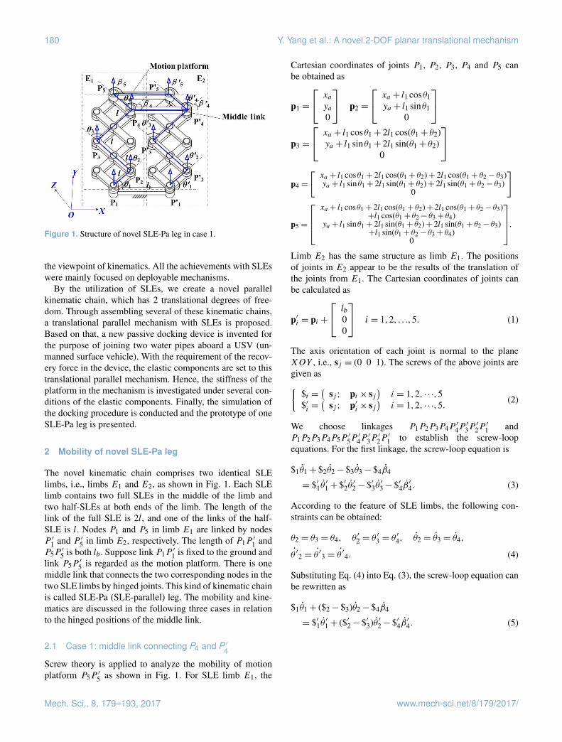
Figure 1. Structure of novel SLE-Pa leg in case 1.
the viewpoint of kinematics. All the achievements with SLEswere mainly focused on deployable mechanisms.
By the utilization of SLEs, we create a novel parallelkinematic chain, which has 2 translational degrees of free-dom. Through assembling several of these kinematic chains,a translational parallel mechanism with SLEs is proposed.Based on that, a new passive docking device is invented forthe purpose of joining two water pipes aboard a USV (un-manned surface vehicle). With the requirement of the recov-ery force in the device, the elastic components are set to thistranslational parallel mechanism. Hence, the stiffness of theplatform in the mechanism is investigated under several con-ditions of the elastic components. Finally, the simulation ofthe docking procedure is conducted and the prototype of oneSLE-Pa leg is presented.
2 Mobility of novel SLE-Pa leg
The novel kinematic chain comprises two identical SLElimbs, i.e., limbs E1 and E2, as shown in Fig. 1. Each SLElimb contains two full SLEs in the middle of the limb andtwo half-SLEs at both ends of the limb. The length of thelink of the full SLE is 2l, and one of the links of the half-SLE is l. Nodes P1 and P5 in limb E1 are linked by nodesP ′1 and P ′5 in limb E2, respectively. The length of P1P
′
1 andP5P
′
5 is both lb. Suppose link P1P′
1 is fixed to the ground andlink P5P
′
5 is regarded as the motion platform. There is onemiddle link that connects the two corresponding nodes in thetwo SLE limbs by hinged joints. This kind of kinematic chainis called SLE-Pa (SLE-parallel) leg. The mobility and kine-matics are discussed in the following three cases in relationto the hinged positions of the middle link.
2.1 Case 1: middle link connecting P4 and P ′4
Screw theory is applied to analyze the mobility of motionplatform P5P
′
5 as shown in Fig. 1. For SLE limb E1, the
Cartesian coordinates of joints P1, P2, P3, P4 and P5 canbe obtained as
p1 =
xaya0
p2 =
xa + l1 cosθ1ya + l1 sinθ1
0
p3 =
xa + l1 cosθ1+ 2l1 cos(θ1+ θ2)ya + l1 sinθ1+ 2l1 sin(θ1+ θ2)
0
p4 =
[xa + l1 cosθ1+ 2l1 cos(θ1+ θ2)+ 2l1 cos(θ1+ θ2− θ3)ya + l1 sinθ1+ 2l1 sin(θ1+ θ2)+ 2l1 sin(θ1+ θ2− θ3)
0
]
p5 =
xa + l1 cosθ1+ 2l1 cos(θ1+ θ2)+ 2l1 cos(θ1+ θ2− θ3)
+l1 cos(θ1+ θ2− θ3+ θ4)ya + l1 sinθ1+ 2l1 sin(θ1+ θ2)+ 2l1 sin(θ1+ θ2− θ3)
+l1 sin(θ1+ θ2− θ3+ θ4)0
.Limb E2 has the same structure as limb E1. The positionsof joints in E2 appear to be the results of the translation ofthe joints from E1. The Cartesian coordinates of joints canbe calculated as
p′i = pi +
lb00
i = 1,2, . . .,5. (1)
The axis orientation of each joint is normal to the planeXOY , i.e., sj = (0 0 1). The screws of the above joints aregiven as{
$i =(
sj ; pi × sj)
i = 1,2, · · ·,5$′i =
(sj ; p′i × sj
)i = 1,2, · · ·,5. (2)
We choose linkages P1P2P3P4P′
4P′
3P′
2P′
1 andP1P2P3P4P5P
′
5P′
4P′
3P′
2P′
1 to establish the screw-loopequations. For the first linkage, the screw-loop equation is
$1θ1+ $2θ2− $3θ3− $4β4
= $′1θ′
1+ $′2θ′
2− $′3θ′
3− $′4β′
4. (3)
According to the feature of SLE limbs, the following con-straints can be obtained:
θ2 = θ3 = θ4, θ ′2 = θ′
3 = θ′
4, θ2 = θ3 = θ4,
θ ′2 = θ′3 = θ
′4. (4)
Substituting Eq. (4) into Eq. (3), the screw-loop equation canbe rewritten as
$1θ1+ ($2− $3)θ2− $4β4
= $′1θ′
1+ ($′2− $′3)θ ′2− $′4β′
4. (5)
Mech. Sci., 8, 179–193, 2017 www.mech-sci.net/8/179/2017/
Y. Yang et al.: A novel 2-DOF planar translational mechanism 181
In the same way, the screw-loop equation of linkageP1P2P3P4P5P
′
5P′
4P′
3P′
2P′
1 can be derived as
$1θ1+ ($2− $3+ $4)θ2− $5β5
= $′1θ′
1+ ($′2− $′3+ $′4)θ ′2− $′5β′
5. (6)
The above Eqs. (5) and (6) can be rearranged in matrix formas
$1 ($2− $3) −$4 0 −$′1−($′2− $′3) $′4 0
$1 ($2− $3+ $4) 0 −$5 −$′1−($′2− $′3+ $′4) 0 $′5
θ1θ2β4β5θ ′1θ ′2β ′4β ′5
= 0. (7)
By solving Eq. (7), the velocities of joints are expressed as
θ1θ2β4β5θ ′1θ ′2β ′4β ′5
= q1
01010101
+ q2
1−1101−110
, (8)
where q1 and q2 are arbitrary real numbers. The result indi-cates that the mobility of this linkage is 2 and that the veloc-ities of joints are subject to the following relationship:
θ1 = θ′
1 = β4 = β′
4, θ2 = θ′
2, β5 = β′
5 = θ1+ θ2. (9)
Equation (9) shows that the two SLE limbs are always paral-lel. Further, the kinematic screw of the platform P5P
′
5 can bewritten as
$p = $1θ1+ ($2− $3+ $4)θ2− $5β5. (10)
Substituting Eq. (8) into Eq. (10), the kinematic screw of theplatform P5P
′
5 can be derived as
$p = q1
000
−sin(θ1+ θ2)cos(θ1+ θ2)
0
+ q2
000
−sinθ1cosθ1
0
. (11)
The corresponding reciprocal screw of the platform can bederived as
$rp :
$r1p =
[0 0 1 0 0 0
]$r2p =
[0 0 0 1 0 0
]$r3p =
[0 0 0 0 1 0
]$r4p =
[0 0 0 0 0 1
]. (12)
Equations (11) and (12) indicates that the motion platform ofthe SLE-Pa leg has 2 pure translational degrees of freedom.
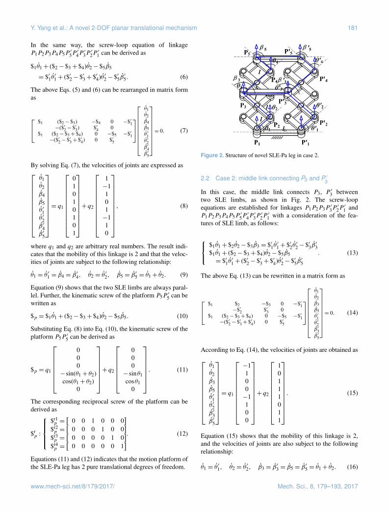
Figure 2. Structure of novel SLE-Pa leg in case 2.
2.2 Case 2: middle link connecting P3 and P ′3
In this case, the middle link connects P3, P ′3 betweentwo SLE limbs, as shown in Fig. 2. The screw-loopequations are established for linkages P1P2P3P
′
3P′
2P′
1 andP1P2P3P4P5P
′
5P′
4P′
3P′
2P′
1 with a consideration of the fea-tures of SLE limb, as follows:
$1θ1+ $2θ2− $3β3 = $′1θ
′
1+ $′2θ′
2− $′3β′
3$1θ1+ ($2− $3+ $4)θ2− $5β5= $′1θ
′
1+ ($′2− $′3+ $′4)θ ′2− $′5β′
5
. (13)
The above Eq. (13) can be rewritten in a matrix form as
$1 $2 −$3 0 −$′1−$′2 $′3 0
$1 ($2− $3+ $4) 0 −$5 −$′1−($′2− $′3+ $′4) 0 $′5
θ1θ2β3β5θ ′1θ ′2β ′3β ′5
= 0. (14)
According to Eq. (14), the velocities of joints are obtained as
θ1θ2β3β5θ ′1θ ′2β ′3β ′5
= q1
−1100−1100
+ q2
10111011
. (15)
Equation (15) shows that the mobility of this linkage is 2,and the velocities of joints are also subject to the followingrelationship:
θ1 = θ′
1, θ2 = θ′
2, β3 = β′
3 = β5 = β′
5 = θ1+ θ2. (16)
www.mech-sci.net/8/179/2017/ Mech. Sci., 8, 179–193, 2017
182 Y. Yang et al.: A novel 2-DOF planar translational mechanism
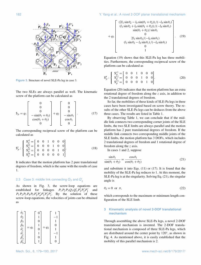
Figure 3. Structure of novel SLE-Pa leg in case 3.
The two SLEs are always parallel as well. The kinematicscrew of the platform can be calculated as
$p = q1
000
−sin(θ1+ θ2)cos(θ1+ θ2)
0
+ q2
000
−sinθ1cosθ1
0
. (17)
The corresponding reciprocal screw of the platform can becalculated as
$rp :
$r1p =
[0 0 1 0 0 0
]$r2p =
[0 0 0 1 0 0
]$r3p =
[0 0 0 0 1 0
]$r4p =
[0 0 0 0 0 1
]. (18)
It indicates that the motion platform has 2 pure translationaldegrees of freedom, which is the same with the results of case1.
2.3 Case 3: middle link connecting Q3 and Q′3
As shown in Fig. 3, the screw-loop equations areestablished for linkages P1P2P3Q3Q
′
3P′
3P′
2P′
1 andP1P2P3P4P5P
′
5P′
4P′
3P′
2P′
1. By the solution of thesescrew-loop equations, the velocities of joints can be obtainedas
θ1θ2β3β5θ ′1θ ′2β ′3β ′5
= q1
01010101
+ q2
1−1101−110
+ q3
(2l1 sinθ2− lb sin(θ1+ θ2))/(−lb sinθ1)(l1 sinθ2+ lb sin(θ1+ θ2))/(−lb sinθ1)
sin(θ1+ θ2)/sinθ10
2l1 sinθ2/(−lb sinθ1)(l1 sinθ2− lb sinθ1)/(−lb sinθ1)
01
. (19)
Equation (19) shows that this SLE-Pa leg has three mobili-ties. Furthermore, the corresponding reciprocal screw of theplatform can be calculated as
$rp :
$r1p =
[0 0 1 0 0 0
]$r2p =
[0 0 0 1 0 0
]$r3p =
[0 0 0 0 1 0
]. (20)
Equation (20) indicates that the motion platform has an extrarotational degree of freedom along the z axis, in addition tothe 2 translational degrees of freedom.
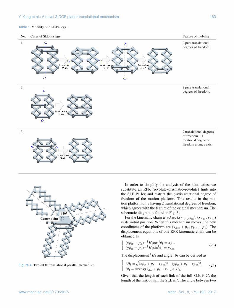
So far, the mobilities of these kinds of SLE-Pa legs in threecases have been investigated based on screw theory. The re-sults of the other SLE-Pa legs can be deduces from the abovethree cases. The results are listed in Table 1.
By observing Table 1, we can conclude that if the mid-dle link connects two corresponding corner joints of the SLElimbs, the two SLE limbs are always parallel and the motionplatform has 2 pure translational degrees of freedom. If themiddle link connects two corresponding middle joints of theSLE limbs, the motion platform has 3 DOFs, which includes2 translational degrees of freedom and 1 rotational degree offreedom along the z axis.
In cases 1 and 2, suppose
sinθ1
sin(θ1+ θ2)=
cosθ1
cos(θ1+ θ2)(21)
and substitute it into Eqs. (11) or (17). It is found that themobility of the SLE-Pa leg reduces to 1. At this moment, theSLE-Pa leg is at the singularity. Solving Eq. (21), the singularangle is
θ2 = 0 or π, (22)
which corresponds to the maximum or minimum length con-figuration of the SLE limb.
3 Kinematic analysis of novel 2-DOF translationalmechanism
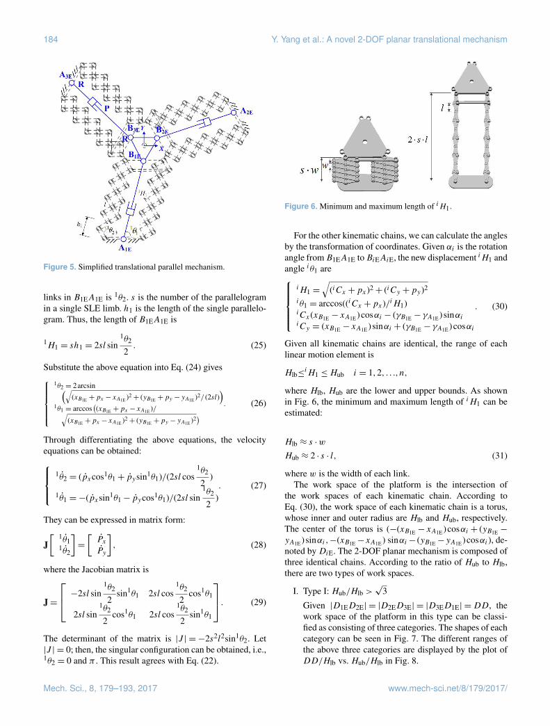
Through assembling the above SLE-Pa legs, a novel 2-DOFtranslational mechanism is invented. The 2-DOF transla-tional mechanism is composed of three SLE-Pa legs, whichare distributed around the center point by 120◦, as shown inFig. 4. As mentioned above, it is easily established that themobility of this parallel mechanism is 2.
Mech. Sci., 8, 179–193, 2017 www.mech-sci.net/8/179/2017/
Y. Yang et al.: A novel 2-DOF planar translational mechanism 183
Table 1. Mobility of SLE-Pa legs.
No. Cases of SLE-Pa legs Feature of mobility
1
20
Table 1. Mobility of SLE-Pa legs
No. Cases of SLE-Pa legs Feature of mobility
1
2 pure translational
degrees of freedom.
2
2 pure translational
degrees of freedom.
3
2 translational
degrees of
freedom+1
rotational degree of
freedom along z-
axis
5
2 pure translationaldegrees of freedom.
2
20
Table 1. Mobility of SLE-Pa legs
No. Cases of SLE-Pa legs Feature of mobility
1
2 pure translational
degrees of freedom.
2
2 pure translational
degrees of freedom.
3
2 translational
degrees of
freedom+1
rotational degree of
freedom along z-
axis
5
2 pure translationaldegrees of freedom.
3
20
Table 1. Mobility of SLE-Pa legs
No. Cases of SLE-Pa legs Feature of mobility
1
2 pure translational
degrees of freedom.
2
2 pure translational
degrees of freedom.
3
2 translational
degrees of
freedom+1
rotational degree of
freedom along z-
axis
5
2 translational degreesof freedom+ 1rotational degree offreedom along z axis
Figure 4. Two-DOF translational parallel mechanism.
In order to simplify the analysis of the kinematics, wesubstitute an RPR (revolute–prismatic–revolute) limb intothe SLE-Pa leg and restrict the z-axis rotational degree offreedom of the motion platform. This results in the mo-tion platform only having 2 translational degrees of freedom,which agrees with the feature of the original mechanism. Theschematic diagram is found in Fig. 5.
For the kinematic chain B1EA1E, (xB1E ,yB1E ), (xA1E ,yA1E )is its initial position. When this mechanism moves, the newcoordinates of the platform are (xB1E +px,yB1E +py). Thedisplacement equations of one RPR kinematic chain can beobtained as{
(xB1E +px)−1H1cos1θ1 = xA1E
(yB1E +py)−1H1sin1θ1 = yA1E
. (23)
The displacement 1H1 and angle 1θ1 can be derived as{1H1 =
√(xB1E +px − xA1E )2+ (yB1E +py − yA1E )2
1θ1 = arccos((xB1E +px − xA1E )/1H1). (24)
Given that the length of each link of the full SLE is 2l, thelength of the link of half the SLE is l. The angle between two
www.mech-sci.net/8/179/2017/ Mech. Sci., 8, 179–193, 2017
184 Y. Yang et al.: A novel 2-DOF planar translational mechanism
Figure 5. Simplified translational parallel mechanism.
links in B1EA1E is 1θ2. s is the number of the parallelogramin a single SLE limb. h1 is the length of the single parallelo-gram. Thus, the length of B1EA1E is
1H1 = sh1 = 2sl sin1θ2
2. (25)
Substitute the above equation into Eq. (24) gives
1θ2 = 2arcsin(√(xB1E +px − xA1E )2+ (yB1E +py − yA1E )2/ (2sl)
)1θ1 = arccos
((xB1E +px − xA1E )/√
(xB1E +px − xA1E )2+ (yB1E +py − yA1E )2) . (26)
Through differentiating the above equations, the velocityequations can be obtained:
1θ2 = (pxcos1θ1+ pysin1θ1)/(2sl cos1θ2
2)
1θ1 =−(pxsin1θ1− pycos1θ1)/(2sl sin1θ2
2). (27)
They can be expressed in matrix form:
J[ 1θ1
1θ2
]=
[PxPy
], (28)
where the Jacobian matrix is
J=
−2sl sin1θ2
2sin1θ1 2sl cos
1θ2
2cos1θ1
2sl sin1θ2
2cos1θ1 2sl cos
1θ2
2sin1θ1
. (29)
The determinant of the matrix is |J | = −2s2l2sin1θ2. Let|J | = 0; then, the singular configuration can be obtained, i.e.,1θ2 = 0 and π . This result agrees with Eq. (22).
Figure 6. Minimum and maximum length of iH1.
For the other kinematic chains, we can calculate the anglesby the transformation of coordinates. Given αi is the rotationangle fromB1EA1E toBiEAiE, the new displacement iH1 andangle iθ1 are
iH1 =
√(iCx +px)2+ (iCy +py)2
iθ1 = arccos((iCx +px)/iH1)iCx(xB1E − xA1E )cosαi − (γB1E − γA1E ) sinαiiCy = (xB1E − xA1E ) sinαi + (γB1E − γA1E )cosαi
. (30)
Given all kinematic chains are identical, the range of eachlinear motion element is
Hlb≤iH1 ≤Hub i = 1,2, . . .,n,
where Hlb, Hub are the lower and upper bounds. As shownin Fig. 6, the minimum and maximum length of iH1 can beestimated:
Hlb ≈ s ·w
Hub ≈ 2 · s · l, (31)
where w is the width of each link.The work space of the platform is the intersection of
the work spaces of each kinematic chain. According toEq. (30), the work space of each kinematic chain is a torus,whose inner and outer radius are Hlb and Hub, respectively.The center of the torus is (−(xB1E − xA1E )cosαi + (yB1E −
yA1E ) sinαi,−(xB1E−xA1E ) sinαi− (yB1E−yA1E )cosαi), de-noted byDiE. The 2-DOF planar mechanism is composed ofthree identical chains. According to the ratio of Hub to Hlb,there are two types of work spaces.
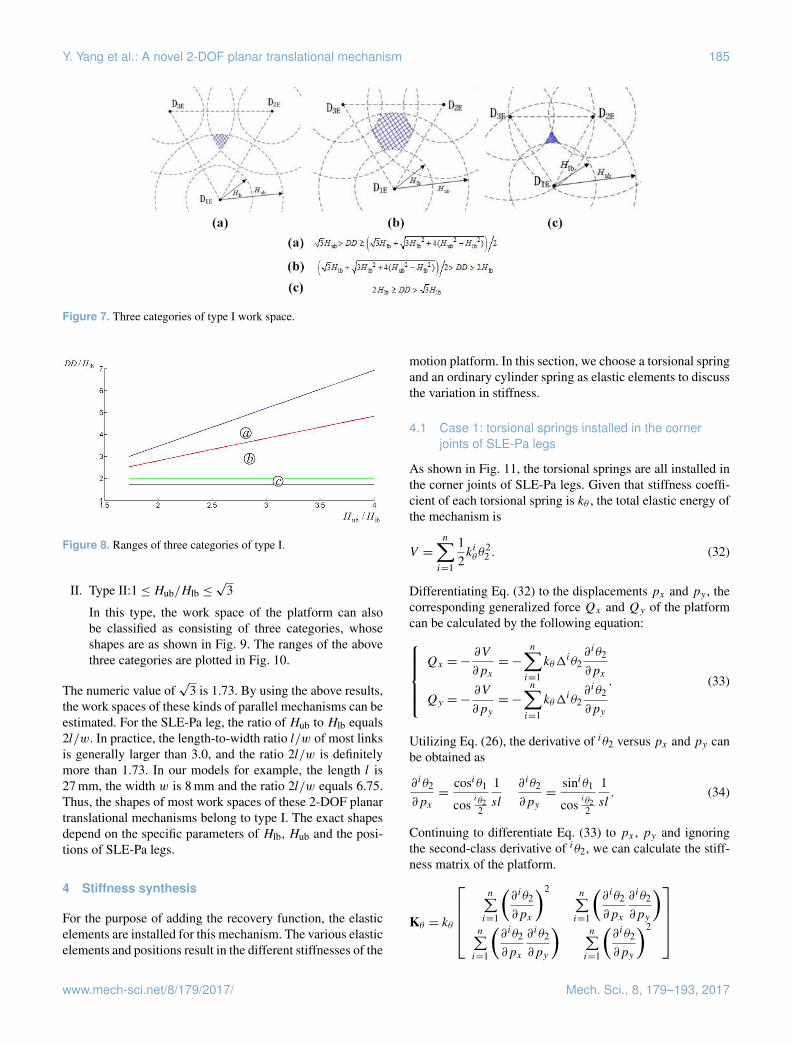
I. Type I: Hub/Hlb >√
3
Given |D1ED2E| = |D2ED3E| = |D3ED1E| =DD, thework space of the platform in this type can be classi-fied as consisting of three categories. The shapes of eachcategory can be seen in Fig. 7. The different ranges ofthe above three categories are displayed by the plot ofDD/Hlb vs. Hub/Hlb in Fig. 8.
Mech. Sci., 8, 179–193, 2017 www.mech-sci.net/8/179/2017/
Y. Yang et al.: A novel 2-DOF planar translational mechanism 185
Figure 7. Three categories of type I work space.
Figure 8. Ranges of three categories of type I.
II. Type II:1≤Hub/Hlb ≤√
3
In this type, the work space of the platform can alsobe classified as consisting of three categories, whoseshapes are as shown in Fig. 9. The ranges of the abovethree categories are plotted in Fig. 10.
The numeric value of√
3 is 1.73. By using the above results,the work spaces of these kinds of parallel mechanisms can beestimated. For the SLE-Pa leg, the ratio of Hub to Hlb equals2l/w. In practice, the length-to-width ratio l/w of most linksis generally larger than 3.0, and the ratio 2l/w is definitelymore than 1.73. In our models for example, the length l is27 mm, the width w is 8 mm and the ratio 2l/w equals 6.75.Thus, the shapes of most work spaces of these 2-DOF planartranslational mechanisms belong to type I. The exact shapesdepend on the specific parameters of Hlb, Hub and the posi-tions of SLE-Pa legs.
4 Stiffness synthesis
For the purpose of adding the recovery function, the elasticelements are installed for this mechanism. The various elasticelements and positions result in the different stiffnesses of the
motion platform. In this section, we choose a torsional springand an ordinary cylinder spring as elastic elements to discussthe variation in stiffness.
4.1 Case 1: torsional springs installed in the cornerjoints of SLE-Pa legs
As shown in Fig. 11, the torsional springs are all installed inthe corner joints of SLE-Pa legs. Given that stiffness coeffi-cient of each torsional spring is kθ , the total elastic energy ofthe mechanism is
V =
n∑i=1
12kiθθ
22 . (32)
Differentiating Eq. (32) to the displacements px and py , thecorresponding generalized force Qx and Qy of the platformcan be calculated by the following equation:Qx =−
∂V
∂px=−
n∑i=1
kθ1iθ2∂ iθ2
∂px
Qy =−∂V
∂py=−
n∑i=1
kθ1iθ2∂ iθ2
∂py
. (33)
Utilizing Eq. (26), the derivative of iθ2 versus px and py canbe obtained as
∂ iθ2
∂px=
cosiθ1
cosiθ22
1sl
∂ iθ2
∂py=
siniθ1
cosiθ22
1sl. (34)
Continuing to differentiate Eq. (33) to px , py and ignoringthe second-class derivative of iθ2, we can calculate the stiff-ness matrix of the platform.
Kθ = kθ
n∑i=1
(∂ iθ2
∂px
)2 n∑i=1
(∂ iθ2
∂px
∂ iθ2
∂py
)n∑i=1
(∂ iθ2
∂px
∂ iθ2
∂py
)n∑i=1
(∂ iθ2
∂py
)2
www.mech-sci.net/8/179/2017/ Mech. Sci., 8, 179–193, 2017
186 Y. Yang et al.: A novel 2-DOF planar translational mechanism
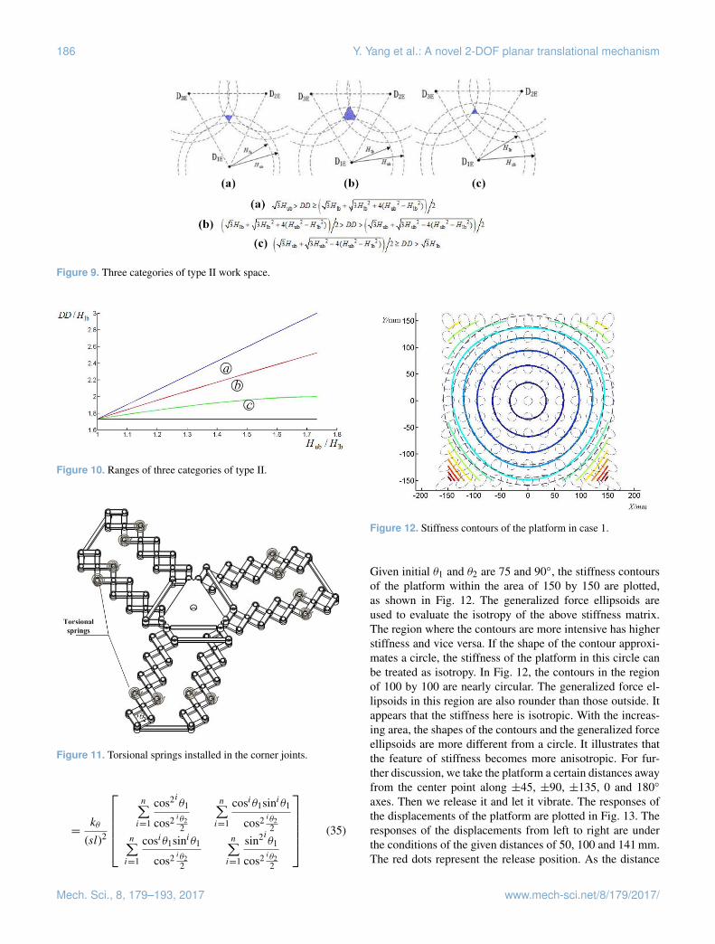
Figure 9. Three categories of type II work space.
Figure 10. Ranges of three categories of type II.
Figure 11. Torsional springs installed in the corner joints.
=kθ
(sl)2
n∑i=1
cos2iθ1
cos2 iθ22
n∑i=1
cosiθ1siniθ1
cos2 iθ22
n∑i=1
cosiθ1siniθ1
cos2 iθ22
n∑i=1
sin2iθ1
cos2 iθ22
(35)
Figure 12. Stiffness contours of the platform in case 1.
Given initial θ1 and θ2 are 75 and 90◦, the stiffness contoursof the platform within the area of 150 by 150 are plotted,as shown in Fig. 12. The generalized force ellipsoids areused to evaluate the isotropy of the above stiffness matrix.The region where the contours are more intensive has higherstiffness and vice versa. If the shape of the contour approxi-mates a circle, the stiffness of the platform in this circle canbe treated as isotropy. In Fig. 12, the contours in the regionof 100 by 100 are nearly circular. The generalized force el-lipsoids in this region are also rounder than those outside. Itappears that the stiffness here is isotropic. With the increas-ing area, the shapes of the contours and the generalized forceellipsoids are more different from a circle. It illustrates thatthe feature of stiffness becomes more anisotropic. For fur-ther discussion, we take the platform a certain distances awayfrom the center point along ±45, ±90, ±135, 0 and 180◦
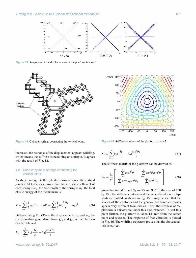
axes. Then we release it and let it vibrate. The responses ofthe displacements of the platform are plotted in Fig. 13. Theresponses of the displacements from left to right are underthe conditions of the given distances of 50, 100 and 141 mm.The red dots represent the release position. As the distance
Mech. Sci., 8, 179–193, 2017 www.mech-sci.net/8/179/2017/
Y. Yang et al.: A novel 2-DOF planar translational mechanism 187
Figure 13. Responses of the displacements of the platform in case 1.
Figure 14. Cylinder springs connecting the vertical joints.
increases, the response of the displacement appears whirling,which means the stiffness is becoming anisotropic. It agreeswith the result of Fig. 12.
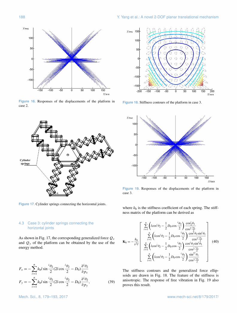
4.2 Case 2: cylinder springs connecting thevertical joints
As shown in Fig. 14, the cylinder springs connect the verticaljoints in SLE-Pa legs. Given that the stiffness coefficient ofeach spring is kv, the free length of the spring is h0; the totalelastic energy of the mechanism is
V =
n∑i=1
12kv(ih1−h0)2
=
n∑i=1
12kv(
iH1
s−h0)2. (36)
Differentiating Eq. (36) to the displacements px and py , thecorresponding generalized force Qx and Qy of the platformcan be obtained:
Fx =
n∑i=1
kv(iH1
s−h0)
cosiθ1
s
Figure 15. Stiffness contours of the platform in case 2.
Fy =
n∑i=1
kv(iH1
s−h0)
siniθ1
s. (37)
The stiffness matrix of the platform can be derived as
Kv =kv
s2
n∑i=1
cos2iθ1n∑i=1
cosiθ1siniθ1
n∑i=1
cosiθ1siniθ1n∑i=1
sin2iθ1
, (38)
given that initial θ1 and θ2 are 75 and 90◦. In the area of 150by 150, the stiffness contours and the generalized force ellip-soids are plotted, as shown in Fig. 15. It may be seen that theshapes of the contours and the generalized force ellipsoidsappear very different from circles. Thus, the stiffness of theplatform is anisotropic under this circumstance. To test thispoint further, the platform is taken 141 mm from the centerpoint and released. The response of free vibration is plottedin Fig. 16. The whirling trajectory proves that the above anal-ysis is correct.
www.mech-sci.net/8/179/2017/ Mech. Sci., 8, 179–193, 2017
188 Y. Yang et al.: A novel 2-DOF planar translational mechanism
Figure 16. Responses of the displacements of the platform incase 2.
Figure 17. Cylinder springs connecting the horizontal joints.
4.3 Case 3: cylinder springs connecting thehorizontal joints
As shown in Fig. 17, the corresponding generalized forceQx
and Qy of the platform can be obtained by the use of theenergy method.
Fx =−
n∑i=1
khl siniθ2
2(2l cos
iθ2
2−D0)
∂ iθ2
∂px
Fy =−
n∑i=1
khl siniθ2
2(2l cos
iθ2
2−D0)
∂ iθ2
∂py, (39)
Figure 18. Stiffness contours of the platform in case 3.
Figure 19. Responses of the displacements of the platform incase 3.
where kh is the stiffness coefficient of each spring. The stiff-ness matrix of the platform can be derived as
Kh =−kh
s2l
n∑i=1
(lcosiθ2−
12D0 cos
iθ2
2
)cosi2θ1
cos2 iθ22
n∑i=1
(lcosiθ2−
12D0 cos
iθ2
2
)cosiθ1siniθ1
cos2 iθ22
n∑i=1
(lcosiθ2−
12D0 cos
iθ2
2
)cosiθ1siniθ1
cos2 iθ22
n∑i=1
(lcosiθ2−
12D0 cos
iθ2
2
)sin2iθ1
cos2 iθ22
(40)
The stiffness contours and the generalized force ellip-soids are drawn in Fig. 18. The feature of the stiffness isanisotropic. The response of free vibration in Fig. 19 alsoproves this result.
Mech. Sci., 8, 179–193, 2017 www.mech-sci.net/8/179/2017/
Y. Yang et al.: A novel 2-DOF planar translational mechanism 189
Figure 20. Cylinder springs connecting vertical joints and horizon-tal joints.
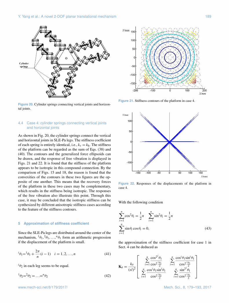
4.4 Case 4: cylinder springs connecting vertical jointsand horizontal joints
As shown in Fig. 20, the cylinder springs connect the verticaland horizontal joints in SLE-Pa legs. The stiffness coefficientof each spring is entirely identical, i.e., kv = kh. The stiffnessof the platform can be regarded as the sum of Eqs. (38) and(40). The contours and the generalized force ellipsoids canbe drawn, and the response of free vibration is displayed inFigs. 21 and 22. It is found that the stiffness of the platformappears to be isotropic in this compound connection. By thecomparison of Figs. 15 and 18, the reason is found that theconvexities of the contours in these two figures are the op-posite of one another. This means that the recovery forcesof the platform in these two cases may be complementary,which results in the stiffness being isotropic. The responsesof the free vibration also illustrate this point. Through thiscase, it may be concluded that the isotropic stiffness can besynthesized by different anisotropic stiffness cases accordingto the feature of the stiffness contours.
5 Approximation of stiffness coefficient
Since the SLE-Pa legs are distributed around the center of themechanism, 1θ1,
2θ1, . . .,nθ1 form an arithmetic progression
if the displacement of the platform is small.
iθ1=1θ1+
2πn
(i− 1) i = 1,2, . . .,n (41)
iθ2 in each leg seems to be equal.
1θ2=2θ2 = . . .=
nθ2 (42)
Figure 21. Stiffness contours of the platform in case 4.
Figure 22. Responses of the displacements of the platform incase 4.
With the following condition
n∑i=1
cos2θi =12n
n∑i=1
sin2θi =12n
n∑i=1
sinθi cosθi = 0, (43)
the approximation of the stiffness coefficient for case 1 inSect. 4 can be deduced as
Kθ =kθ
(sl)2
n∑i=1
cos2iθ1
cos2 iθ22
n∑i=1
cosiθ1siniθ1
cos2 iθ22
n∑i=1
cosiθ1siniθ1
cos2 iθ22
n∑i=1
sin2iθ1
cos2 iθ22
www.mech-sci.net/8/179/2017/ Mech. Sci., 8, 179–193, 2017
190 Y. Yang et al.: A novel 2-DOF planar translational mechanism
Figure 23. Passive docking device.
=kθ
(sl)2cos2 0θ22
12n 0
012n
. (44)
In the same way, the approximation of the stiffness coeffi-cient for cases 2 and 3 is
Kv =kv
s2
n∑i=1
cos2iθ1n∑i=1
cosiθ1siniθ1
n∑i=1
cosiθ1siniθ1n∑i=1
sin2iθ1
=kv
s2
12n 0
012n
, (45)
Kh =−kh
s2l
(lcos0θ2−
12D0 cos
0θ22
)cos2 0θ2
2
12n 0
012n
=kh
s2 tan20θ2
2
12n 0
012n
. (46)
The approximation of the stiffness coefficient can be usedfor a preliminary estimate of some parameters, i.e., recoveryforce, vibration frequency and others, before designing themechanism. It is found that the approximation of the stiffnesscoefficient in cases 1 and 3 is related to 0θ2. It means that thestiffness of the platform can be adjusted by changing 0θ2. Ifkv = kh and 0θ2 = 90◦, the stiffness in case 2 and 3 is equal.
6 Design of passive docking device
These novel 2-DOF planar translational mechanisms assem-bled by SLE-Pa legs are applied to the design of a pas-sive docking device, which can be used for joining pipesin a water sample collection system. As shown in Fig. 23,the passive docking device comprises support structure, 2-DOF planar translational mechanism, bellows coupling and
Figure 24. Docking diagram.
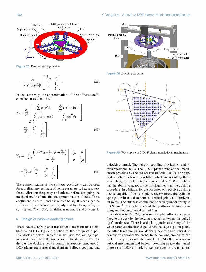
Figure 25. Work space of 2-DOF planar translational mechanism.
a docking tunnel. The bellows coupling provides x- and y-axes rotational DOFs. The 2-DOF planar translational mech-anism provides x- and y-axes translational DOFs. The sup-port structure is taken by a lifter, which moves along the zaxis. Thus, the docking tunnel has a total of 5 DOFs, whichhas the ability to adapt to the misalignments in the dockingprocedure. In addition, for the purposes of a passive dockingdevice capable of an isotropic recovery force, the cylindersprings are installed to connect vertical joints and horizon-tal joints. The stiffness coefficient of each cylinder spring is0.3 N mm−1. The total mass of the platform, bellows cou-pling and docking tunnel is 1.247 kg.
As shown in Fig. 24, the water sample collection cage isfixed to the deck by the holding mechanism when it is pulledup from the sea. There is a docking probe at the top of thewater sample collection cage. When the cage is put in place,the lifter takes the passive docking device and allows it todescend to approach the probe. In the docking procedure, theprobe slowly slides into the tunnel. The 2-DOF planar trans-lational mechanism and bellows coupling enable the tunnelto possess 4 DOFs in order to compensate for the misalign-
Mech. Sci., 8, 179–193, 2017 www.mech-sci.net/8/179/2017/
Y. Yang et al.: A novel 2-DOF planar translational mechanism 191
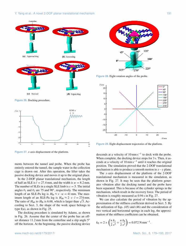
Figure 26. Docking procedure.
Figure 27. x-axis displacement of the platform.
ments between the tunnel and probe. When the probe hasentirely entered the tunnel, the sample water in the collectioncage is drawn out. After this operation, the lifter takes thepassive docking device and moves it up to the original place.
In the 2-DOF planar translational mechanism, the lengthof half an SLE is l = 27.4 mm, and the width is w = 8.2 mm.The number of SLEs in a single SLE limb is s = 5. The initialangles θ1 and θ2 are 75 and 90◦, respectively. The minimumlength of an SLE-Pa leg is Hlb ≈ s ·w = 41 mm. The max-imum length of an SLE-Pa leg is Hub ≈ 2 · s · l = 274 mm.The ratio of Hub to Hlb is 6.68, which is larger than
√3. Ac-
cording to Sect. 3, the shape of the work space belongs totype I(a), as shown in Fig. 25.
The docking procedure is simulated by Adams, as shownin Fig. 26. Assume that the center of the probe has an off-set distance 11.2 mm from the centerline and a slip angle 5◦
off the horizon. At the beginning, the passive docking device
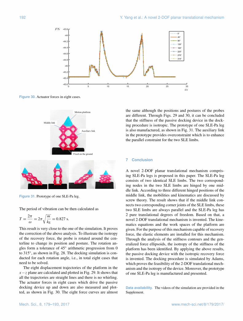
Figure 28. Eight rotation angles of the probe.
Figure 29. Eight displacement trajectories of the platform.
descends at a velocity of 10 mm s−1 to dock with the probe.When complete, the docking device stops for 3 s. Then, it as-cends at a velocity of 10 mm s−1 until it reaches the originalposition. The simulation proved that the 2-DOF translationalmechanism is able to produce a smooth motion in x−y plane.
The x-axis displacement of the platform of the 2-DOFtranslational mechanism is measured in the simulation, asshown in Fig. 27. It may be seen that the platform gener-ates vibration after the docking tunnel and the probe havebeen separated. This is because of the cylinder springs in themechanism, which result in the recovery force. The period ofvibration is roughly measured as 0.94 s in Fig. 27.
We can also calculate the period of vibration by the ap-proximation of the stiffness coefficient derived in Sect. 5. Bythe utilization of Eqs. (45) and (46) and the consideration oftwo vertical and horizontal springs in each leg, the approxi-mation of the stiffness coefficient can be obtained.
kE = 2×(n
2kv
s2 +n
2kh
s2
)= 0.072 Nmm−1.
www.mech-sci.net/8/179/2017/ Mech. Sci., 8, 179–193, 2017
192 Y. Yang et al.: A novel 2-DOF planar translational mechanism
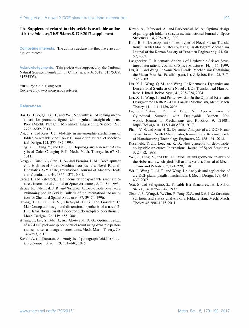
Figure 30. Actuator forces in eight cases.
Prototype of one SLE-Pa leg
Motion platform
Fixed on the ground
Middle link
Auxiliary link
Figure 31. Prototype of one SLE-Pa leg.
The period of vibration can be then calculated as
T =2πω= 2π
√m
kE= 0.827 s.
This result is very close to the one of the simulation. It provesthe correction of the above analysis. To illustrate the isotropyof the recovery force, the probe is rotated around the cen-terline to change its position and posture. The rotation an-gles form a tolerance of 45◦ arithmetic progression from 0to 315◦, as shown in Fig. 28. The docking simulation is con-ducted for each rotation angle, i.e., in total eight cases thatneed to be solved.
The eight displacement trajectories of the platform in thex−z plane are calculated and plotted in Fig. 29. It shows thatall the trajectories are straight lines and there is no whirling.The actuator forces in eight cases which drive the passivedocking device up and down are also measured and plot-ted, as shown in Fig. 30. The eight force curves are almost
the same although the positions and postures of the probesare different. Through Figs. 29 and 30, it can be concludedthat the stiffness of the passive docking device in the dock-ing procedure is isotropic. The prototype of one SLE-Pa legis also manufactured, as shown in Fig. 31. The auxiliary linkin the prototype provides overconstraint which is to enhancethe parallel constraint for the two SLE limbs.
7 Conclusion
A novel 2-DOF planar translational mechanism compris-ing SLE-Pa legs is proposed in this paper. The SLE-Pa legconsists of two identical SLE limbs. The two correspond-ing nodes in the two SLE limbs are hinged by one mid-dle link. According to three different hinged positions of themiddle link, the mobilities and kinematics are discussed byscrew theory. The result shows that if the middle link con-nects two corresponding corner joints of the SLE limbs, thesetwo SLE limbs are always parallel and the SLE-Pa leg has2 pure translational degrees of freedom. Based on that, anovel 2-DOF translational mechanism is invented. The kine-matics equations and the work spaces of the platform aregiven. For the purpose of this mechanism capable of recoveryforce, the elastic elements are installed for this mechanism.Through the analysis of the stiffness contours and the gen-eralized force ellipsoids, the isotropy of the stiffness of theplatform has been identified. By applying the above results,the passive docking device with the isotropic recovery forceis invented. The docking procedure is simulated by Adams,which proves the feasibility of the 2-DOF translational mech-anism and the isotropy of the device. Moreover, the prototypeof one SLE-Pa leg is manufactured and presented.
Data availability. The videos of the simulation are provided in theSupplement.
Mech. Sci., 8, 179–193, 2017 www.mech-sci.net/8/179/2017/
Y. Yang et al.: A novel 2-DOF planar translational mechanism 193
The Supplement related to this article is available onlineat https://doi.org/10.5194/ms-8-179-2017-supplement.
Competing interests. The authors declare that they have no con-flict of interest.
Acknowledgements. This project was supported by the NationalNatural Science Foundation of China (nos. 51675318, 51575329,61525305).
Edited by: Chin-Hsing KuoReviewed by: two anonymous referees
References
Bai, G., Liao, Q., Li, D., and Wei, S.: Synthesis of scaling mech-anisms for geometric figures with angulated-straight elements,Proc IMechE Part C: J Mechanical Engineering Science, 227,2795–2809, 2013.
Dai, J. S. and Rees, J. J.: Mobility in metamorphic mechanisms offoldable/erectable kinds, ASME Transaction Journal of Mechan-ical Design, 121, 375–382, 1999.
Ding, X. L., Yang, Y., and Dai, J. S.: Topology and Kinematic Anal-ysis of Color-Changing Ball, Mech. Mach. Theory, 46, 67–81,2011.
Dong, J., Yuan, C., Stori, J. A., and Ferreira, P. M.: Developmentof a High-speed 3-axis Machine Tool using a Novel Parallel-kinematics X-Y Table, International Journal of Machine Toolsand Manufacture, 44, 1355–1371, 2004.
Escrig, F. and Valcarcel, J. P.: Geometry of expandable space struc-tures, International Journal of Space Structures, 8, 71–84, 1993.
Escrig, F., Valcarcel, J. P., and Sanchez, J.: Deployable cover on aswimming pool in Seville, Bulletin of the International Associa-tion for Shell and Spatial Structures, 37, 39–70, 1996.
Huang, T., Li, Z., Li, M., Chetwynd, D. G., and Gosselin, C.M.: Conceptual design and dimensional synthesis of a novel 2-DOF translational parallel robot for pick-and-place operations, J.Mech. Design, 126, 449–455, 2004.
Huang, T., Liu, S., Mei, J., and Chetwynd, D. G.: Optimal designof a 2-DOF pick-and-place parallel robot using dynamic perfor-mance indices and angular constraints, Mech. Mach. Theory, 70,246–253, 2013.
Kaveh, A. and Davaran, A.: Analysis of pantograph foldable struc-ture, Comput. Struct., 59, 131–140, 1996.
Kaveh, A., Jafarvand, A., and Barkhordari, M. A.: Optimal designof pantograph foldable structures, International Journal of SpaceStructures, 14, 295–302, 1999.
Kim, H. S.: Development of Two Types of Novel Planar Transla-tional Parallel Manipulators by using Parallelogram Mechanism,Journal of the Korean Society of Precision Engineering, 24, 50–57, 2007.
Langbecker, T.: Kinematic Analysis of Deployable Scissor Struc-tures, International Journal of Space Structures, 14, 1–15, 1999.
Liu, X. J. and Wang, J.: Some New Parallel Mechanisms Containingthe Planar Four-Bar Parallelogram, Int. J. Robot. Res., 22, 717–732, 2003.
Liu, X. J., Wang, Q. M., and Wang, J.: Kinematics, Dynamics andDimensional Synthesis of a Novel 2-DOF Translational Manipu-lator, J. Intell. Robot. Syst., 41, 205–224, 2004.
Liu, X. J., Wang, J., and Pritschow, G.: On the Optimal KinematicDesign of the PRRRP 2-DOF Parallel Mechanism, Mech. Mach.Theory, 41, 1111–1130, 2006.
Lu, S., Zlatanov, D., and Ding, X.: Approximation ofCylindrical Surfaces with Deployable Bennett Net-works, Journal of Mechanisms and Robotics, 9, 021001,https://doi.org/10.1115/1.4035801, 2017.
Pham, V. N. and Kim, H. S.: Dynamics Analysis of a 2-DOF PlanarTranslational Parallel Manipulator, Journal of the Korean Societyof Manufacturing Technology Engineers, 22, 185–191, 2013.
Rosenfeld, Y. and Logcher, R. D.: New concepts for deployable-collapsable structures, International Journal of Space Structures,3, 20–32, 1988.
Wei, G., Ding, X., and Dai, J S.: Mobility and geometric analysis ofthe Hoberman switch-pitch ball and its variant, Journal of Mech-anisms and Robotics, 2, 191–220, 2010.
Wu, J., Wang, J., Li, T., and Wang, L.: Analysis and application ofa 2-DOF planar parallel mechanism, J. Mech. Design, 129, 434–437, 2007.
You, Z. and Pellegrino, S.: Foldable Bar Structures, Int. J. SolidsStruct., 34, 1825–1847, 1997.
Zhao, J. S., Wang, J. Y., Chu, F., Feng, Z. J., and Dai, J. S.: Structuresynthesis and statics analysis of a foldable stair, Mech. Mach.Theory, 46, 998–1015, 2011.
www.mech-sci.net/8/179/2017/ Mech. Sci., 8, 179–193, 2017