Embed Size (px)
Citation preview

968 IEEE TRANSACTIONS ON MAGNETICS, VOL. 49, NO. 3, MARCH 2013
A New Type of Transmission Line-Based Metamaterial Resonator and ItsImplementation in Original Applications
Ousama Abu Safia , Larbi Talbi , and Khelifa Hettak
Univerity of Quebec in Outaouais, Gatineau, Quebec J8Y 3G5, Canada
Communications Research Centre, Ottawa, Ontario K2H 8S2, Canada
In this paper, a new type of transmission line-basedmetamaterial resonator is proposed. The structure is based on amodified uniplanarseries resonator bent to form a close square loop inclusion which contains a distributed capacitance and inductance. Many advantagesof the proposed structure over conventional split ring resonators are discussed. Based on simple transmission line theory, the resonancefrequency at which a deep rejection frequency band occurs with sharp cutoff rates beside the stopband, due to the presence of negativeeffective permeability in the dielectric slab of the host transmission line in the vicinity of resonance, is calculated and verified with sim-ulated and measured results. Two prototype microwave devices are designed to illustrate the potentiality of the proposed inclusion. Thefirst design represents a dual-band bandstop filter with designed center band frequencies at 1.6 and 2.2 GHz. The lumped element modelof this filter contains four series-connected parallel LC resonators which are implemented using our high Q-factor artificial magneticmaterials (AMMs) patterned on the backside of a coplanar waveguide (CPW) transmission line. The second device is a miniaturizedhybrid branch line coupler operating at 2.4 GHz, based on a special loading technique that increases the electric length of transmissionlines by patterning the ground plane under the conductor trace in microstrip lines with the complementary, dual-behavior, configurationof AMMs. A size reduction factor up to 16.95% is achieved compared to conventional couplers. For both design examples the measuredand simulated responses are in very good agreement which validates our work.
Index Terms—Artificial magnetic materials, coplanar waveguide, dual-band filters, hybrid branch line coupler, metamaterials.
I. INTRODUCTION
S PLIT ring resonators (SRRs) were first introduced byPendry et al. [1]. Since then, numerous SRRs having
various geometrical configuration have been proposed [2]–[7].However, most of these SRRs are derived from the prototypestructure proposed in [1]. For example, in [2] a square splitring resonator (S-SRR) was proposed which has more degreesof freedom from a design point of view, and more magneticcoupling with the host transmission line (TL), than SRRs. Antaret al. built a theoretical model for S-SRRs to estimate their res-onance frequency and their magnetic polarization in [3]. Theyalso investigated the bandstop behavior of these resonatorswhen loaded into CPW. In [4], bandstop filters based on SRRsplaced on the back side of CPW substrate were first introduced.These filters give significant insertion loss in the rejectionband with very good frequency selectivity near the resonancefrequency. Baena et al. proposed many SRR topologies withdifferent broken-loop shapes, and their equivalent lumpedelement models, in [5]. Although the number of capacitors andinductors varies in each topology, it can always be simplifiedto a series-connected LC resonator mutually coupled with thehost TL. In [6], a spiral resonator of one metallic planar pieceis proposed in order to facilitate the fabrication process becauseof the absence of the narrow slots between the strips. In [7], amodified broadside coupled SRR was proposed by Marques etal. as an alternative to a conventional SRR in order to avoid thebi-anisotropic effects.
Manuscript received September 17, 2012; revised October 30, 2012; acceptedNovember 15, 2012. Date of current version February 20, 2013. Correspondingauthor: O. Abu Safia (e-mail: [email protected]; [email protected]).Color versions of one or more of the figures in this paper are available online
at http://ieeexplore.ieee.org.Digital Object Identifier 10.1109/TMAG.2012.2230248
The resonance behavior in artificial magnetic materials(AMMs) results from the perpendicular excitation of thetime-varying magnetic field through their sectional areas; there-fore, induced resonating currents flow inside the broken-loopswhich act as magnetic dipole moments. This physical phe-nomenon can be modeled as a series-connected LC resonator,mutually coupled with the host TL [4]. The real part of theeffective permeability within the host dielectric substratemedium encounters a bipolar impulse response in the vicinityof the resonance frequency , i.e., increases positivelyjust before then it falls down to negative values with highslope rate after that [8]. Mapping this phenomenon to filterapplications, it can be concluded that a bandstop response canbe detected in the resonance frequency range.The resonance and dispersive behaviors in SSRs are entirely
determined by the geometry and the size of the metallic broken-loop inclusions [1]. For all the proposed geometries which aredriven from conventional SRRs there are some advantages anddisadvantages. Our goal in this work is to design a new AMMwith the following advantages. Firstly, the distributed capaci-tance and inductance within the resonators can be calculatedaccurately using simple TL theory. This means that we willnot use complex expressions or approximations. Secondly, theproposed geometry should offer the possibility to tune its dis-tributed elements separately, unlike other structures in the lit-erature in which the capacitance and inductance are linked to-gether by many common dimensions [1]–[9]. This will allow usto control the Q-factor in the proposed resonators. Thirdly, theAMM has only one controlling dimension to tune the resonancefrequency as explained in the next section. Finally, the proposedAMM is more compact as compared to conventional AMMs.AMMs are suitable for compact microwave devices such as
filters and diplexers due to their resonance nature, and due tothe controllability of the electrical properties in AMM-based
0018-9464/$31.00 © 2012 IEEE
ABU SAFIA et al.: NEW TYPE OF TRANSMISSION LINE-BASED METAMATERIAL RESONATOR 969
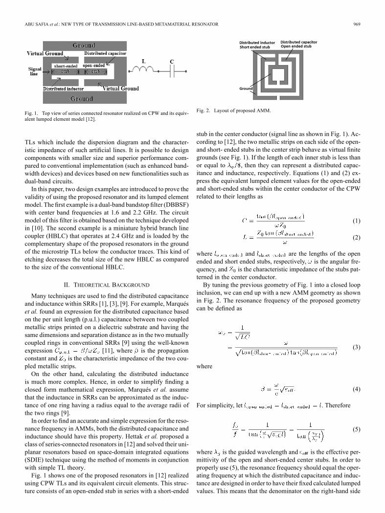
Fig. 1. Top view of series connected resonator realized on CPW and its equiv-alent lumped element model [12].
TLs which include the dispersion diagram and the character-istic impedance of such artificial lines. It is possible to designcomponents with smaller size and superior performance com-pared to conventional implementation (such as enhanced band-width devices) and devices based on new functionalities such asdual-band circuits.In this paper, two design examples are introduced to prove the
validity of using the proposed resonator and its lumped elementmodel. Thefirst example is a dual-band bandstop filter (DBBSF)with center band frequencies at 1.6 and 2.2 GHz. The circuitmodel of this filter is obtained based on the technique developedin [10]. The second example is a miniature hybrid branch linecoupler (HBLC) that operates at 2.4 GHz and is loaded by thecomplementary shape of the proposed resonators in the groundof the microstrip TLs below the conductor traces. This kind ofetching decreases the total size of the new HBLC as comparedto the size of the conventional HBLC.
II. THEORETICAL BACKGROUND
Many techniques are used to find the distributed capacitanceand inductance within SRRs [1], [3], [9]. For example, Marquéset al. found an expression for the distributed capacitance basedon the per unit length (p.u.l.) capacitance between two coupledmetallic strips printed on a dielectric substrate and having thesame dimensions and separation distance as in the two mutuallycoupled rings in conventional SRRs [9] using the well-knownexpression [11], where is the propagationconstant and is the characteristic impedance of the two cou-pled metallic strips.On the other hand, calculating the distributed inductance
is much more complex. Hence, in order to simplify finding aclosed form mathematical expression, Marqués et al. assumethat the inductance in SRRs can be approximated as the induc-tance of one ring having a radius equal to the average radii ofthe two rings [9].In order to find an accurate and simple expression for the reso-
nance frequency in AMMs, both the distributed capacitance andinductance should have this property. Hettak et al. proposed aclass of series-connected resonators in [12] and solved their uni-planar resonators based on space-domain integrated equations(SDIE) technique using the method of moments in conjunctionwith simple TL theory.Fig. 1 shows one of the proposed resonators in [12] realized
using CPW TLs and its equivalent circuit elements. This struc-ture consists of an open-ended stub in series with a short-ended
Fig. 2. Layout of proposed AMM.
stub in the center conductor (signal line as shown in Fig. 1). Ac-cording to [12], the two metallic strips on each side of the open-and short- ended stubs in the center strip behave as virtual finitegrounds (see Fig. 1). If the length of each inner stub is less thanor equal to , then they can represent a distributed capac-itance and inductance, respectively. Equations (1) and (2) ex-press the equivalent lumped element values for the open-endedand short-ended stubs within the center conductor of the CPWrelated to their lengths as
(1)
(2)
where and are the lengths of the openended and short ended stubs, respectively, is the angular fre-quency, and is the characteristic impedance of the stubs pat-terned in the center conductor.By tuning the previous geometry of Fig. 1 into a closed loop
inclusion, we can end up with a new AMM geometry as shownin Fig. 2. The resonance frequency of the proposed geometrycan be defined as
(3)
where
(4)
For simplicity, let . Therefore
(5)
where is the guided wavelength and is the effective per-mittivity of the open and short-ended center stubs. In order toproperly use (5), the resonance frequency should equal the oper-ating frequency at which the distributed capacitance and induc-tance are designed in order to have their fixed calculated lumpedvalues. This means that the denominator on the right-hand side

970 IEEE TRANSACTIONS ON MAGNETICS, VOL. 49, NO. 3, MARCH 2013
of (5) should equal unity. Hence, the equal length of the openand short ended stubs can be given as
(6)
The following results can be concluded from the previousequations. Firstly, the resonance frequency depends only on onedimension (i.e., the stubs’ lengths), unlike SRR or other AMMsderived from conventional SRRs.Secondly, we can independently tune the values of the dis-
tributed passive elements by changing the length of the innerstubs. This property gives an advantage over SRRs, whose dis-tributed capacitance and inductance are linked together bymanycommon geometrical dimensions. Hence, using the proposedAMM the quality factors in AMM-based microwave circuitscan be simply controlled by independently changing the stubs’length. This property can significantly enhance and control thepassbands, stopbands, and the fractional bandwidths in AMM-based filters.Thirdly, the resonance frequency does not depend on the char-
acteristic impedance of the open and short-ended stubs. Thisproperty gives us more design flexibility in choosing the widthof the center stubs and the spacing between the finite groundsand the stubs. Therefore, these dimensions can be decreased toprovide additional compactness, as long as they meet the fabri-cation limits.Fourthly, the resonance frequency of the proposed AMM is
lower than the resonance frequency of a similar-size conven-tional square split resonator as mentioned in the next section.Hence, a significant reduction in the size of the proposed AMMis achieved as compared to a conventional square SRR havingthe same resonance frequency.Fifthly, since the proposed resonator depends on TL theory,
it is possible to scale the lengths of the center stubs (one dimen-sional scaling) in order to linearly shift the resonance frequency.Finally, the expression in (6) is simple, straightforward, and
accurate, as long as the lengths of the inner stubs equal .
III. RESONATOR DESIGN AND RESPONSE
To demonstrate the performance of the proposed structure,a one-period square resonator backed CPW has been designedand fabricated as shown in Fig. 3. The substrate used isRT/Duroid 6010LM, which has a dielectric constant of 10.2,loss tangent of 0.0023, and a thickness of 0.635 mm. Thedesigned resonance frequency of the proposed AMM is 3.4GHz. Hence, using (6) the open- and short-ended stubs withinthe resonators are 4.20 mm given that , which isthe same as for a finite-ground CPW TL having the samedimensions as the inner stubs [13]. Fig. 4 shows the simulatedand measured scattering parameters of the proposed metama-terial-based resonator. We use the full-wave electromagneticsimulator IE3D which is based on the method of momentsto design the AMM [14]. The simulated resonance frequencyappears at 3.35 GHz which is very close to the theoretical value(3.4 GHz). The small difference between the simulated andthe theoretical values can be attributed to the parasitic discon-tinuities in CPW TLs. However, these discontinuities have a
Fig. 3. Layout and photograph of fabricated CPW TL loaded by the proposedAMM. (a) Bottom view. (b) Top view.
Fig. 4. Scattering parameters of our AMM loaded into CPW TL.
TABLE IPERFORMANCE OF PROPOSED AMM (DESIGNED GHZ)
negligible effect on the performance of the AMM. A shift of0.02 GHz in the resonance frequency between the measuredand simulated responses is observed as shown in Fig. 4. Thisshift may be due to fabrication tolerance.Table I summarizes the simulated and measured charac-
teristics of the proposed AMM. The 3-dB bandwidth and theQ-factor can be easily controlled since they are directly linkedto the tunable distributed capacitance and inductance withinthe AMM. Besides its accurate estimated resonance frequency,the proposed AMM shows very good values of insertion loss( 10 dB), return loss ( 2.5 dB) and Q-factor 20 . Hence, itcan be an excellent candidate for resonance-based microwavecircuits.According to [3], the resonance frequency of a conventional
square SRR having the same dimensions as our proposedAMM,and loaded into the same CPW TL, is 4.36 GHz. Hence, the pro-posed AMM has a size reduction factor of 23.62% as comparedto conventional S-SRRs.
ABU SAFIA et al.: NEW TYPE OF TRANSMISSION LINE-BASED METAMATERIAL RESONATOR 971
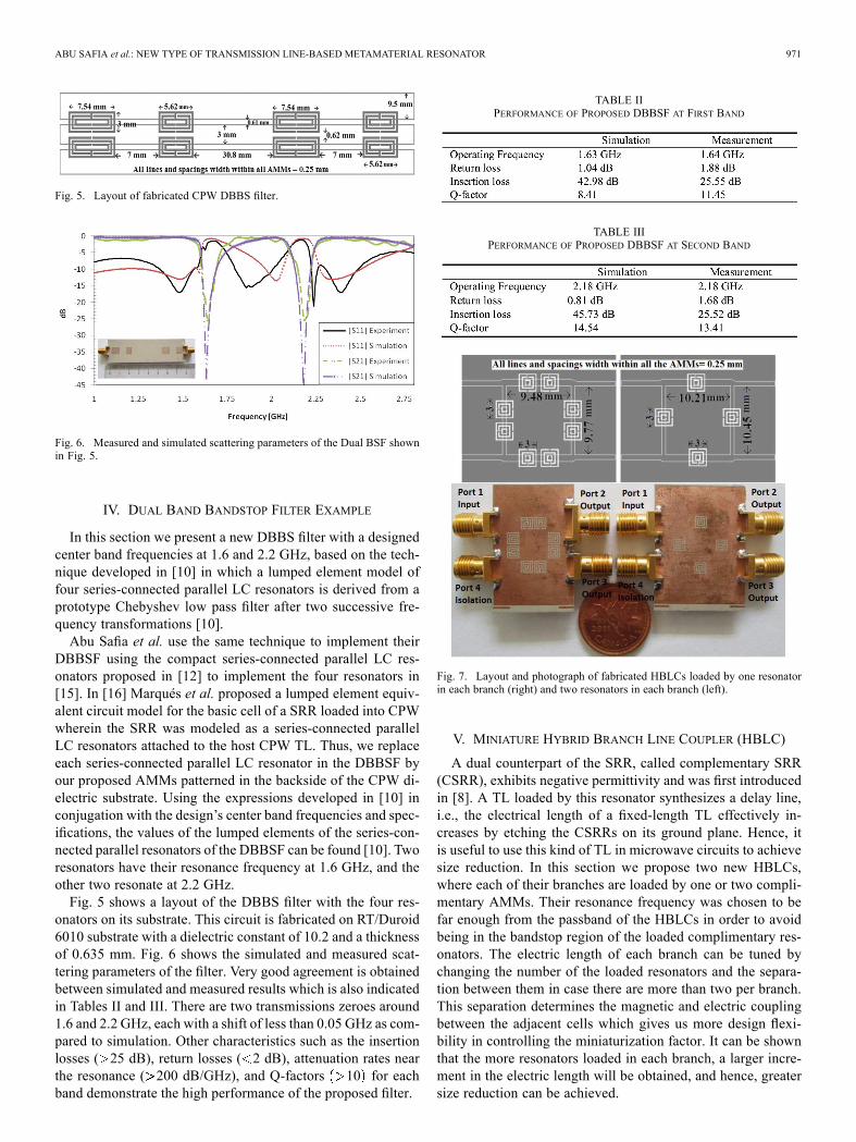
Fig. 5. Layout of fabricated CPW DBBS filter.
Fig. 6. Measured and simulated scattering parameters of the Dual BSF shownin Fig. 5.
IV. DUAL BAND BANDSTOP FILTER EXAMPLE
In this section we present a new DBBS filter with a designedcenter band frequencies at 1.6 and 2.2 GHz, based on the tech-nique developed in [10] in which a lumped element model offour series-connected parallel LC resonators is derived from aprototype Chebyshev low pass filter after two successive fre-quency transformations [10].Abu Safia et al. use the same technique to implement their
DBBSF using the compact series-connected parallel LC res-onators proposed in [12] to implement the four resonators in[15]. In [16] Marqués et al. proposed a lumped element equiv-alent circuit model for the basic cell of a SRR loaded into CPWwherein the SRR was modeled as a series-connected parallelLC resonators attached to the host CPW TL. Thus, we replaceeach series-connected parallel LC resonator in the DBBSF byour proposed AMMs patterned in the backside of the CPW di-electric substrate. Using the expressions developed in [10] inconjugation with the design’s center band frequencies and spec-ifications, the values of the lumped elements of the series-con-nected parallel resonators of the DBBSF can be found [10]. Tworesonators have their resonance frequency at 1.6 GHz, and theother two resonate at 2.2 GHz.Fig. 5 shows a layout of the DBBS filter with the four res-
onators on its substrate. This circuit is fabricated on RT/Duroid6010 substrate with a dielectric constant of 10.2 and a thicknessof 0.635 mm. Fig. 6 shows the simulated and measured scat-tering parameters of the filter. Very good agreement is obtainedbetween simulated and measured results which is also indicatedin Tables II and III. There are two transmissions zeroes around1.6 and 2.2 GHz, each with a shift of less than 0.05 GHz as com-pared to simulation. Other characteristics such as the insertionlosses ( 25 dB), return losses ( 2 dB), attenuation rates nearthe resonance ( 200 dB/GHz), and Q-factors 10 for eachband demonstrate the high performance of the proposed filter.
TABLE IIPERFORMANCE OF PROPOSED DBBSF AT FIRST BAND
TABLE IIIPERFORMANCE OF PROPOSED DBBSF AT SECOND BAND
Fig. 7. Layout and photograph of fabricated HBLCs loaded by one resonatorin each branch (right) and two resonators in each branch (left).
V. MINIATURE HYBRID BRANCH LINE COUPLER (HBLC)
A dual counterpart of the SRR, called complementary SRR(CSRR), exhibits negative permittivity and was first introducedin [8]. A TL loaded by this resonator synthesizes a delay line,i.e., the electrical length of a fixed-length TL effectively in-creases by etching the CSRRs on its ground plane. Hence, itis useful to use this kind of TL in microwave circuits to achievesize reduction. In this section we propose two new HBLCs,where each of their branches are loaded by one or two compli-mentary AMMs. Their resonance frequency was chosen to befar enough from the passband of the HBLCs in order to avoidbeing in the bandstop region of the loaded complimentary res-onators. The electric length of each branch can be tuned bychanging the number of the loaded resonators and the separa-tion between them in case there are more than two per branch.This separation determines the magnetic and electric couplingbetween the adjacent cells which gives us more design flexi-bility in controlling the miniaturization factor. It can be shownthat the more resonators loaded in each branch, a larger incre-ment in the electric length will be obtained, and hence, greatersize reduction can be achieved.
972 IEEE TRANSACTIONS ON MAGNETICS, VOL. 49, NO. 3, MARCH 2013
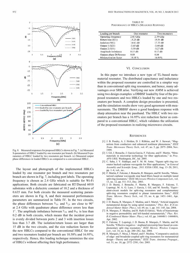
Fig. 8. Measured responses for proposed HBLCs shown in Fig. 7. (a)MeasuredS-parameters of HBLC loaded by one resonator per branch. (b) Measured S-pa-rameters of HBLC loaded by two resonators per branch. (c) Measured outputphase differences in loaded HBLCs as compared to a conventional HBLC.
The layout and photograph of the implemented HBLCsloaded by one resonator per branch and two resonators perbranch are shown in Fig. 7, including port labels. The operatingfrequency is chosen as 2.4 GHz which is suitable for Wi-Fiapplications. Both circuits are fabricated on RT/Duroid 6010substrates with a dielectric constant of 10.2 and a thickness of0.635 mm. For both circuits the measured scattering param-eters are shown in Fig. 8, and their measured performancesparameters are summarized in Table IV. In the two circuits,the phase differences between and are close to 90at 2.4 GHz with quadrature phase difference errors less than1 . The amplitude imbalance between and is less than0.2 dB in both circuits, which means that the incident poweris evenly divided between ports 2 and 3 with insertion lossesless than 3.7 dB. The isolation/return losses are larger than15 dB in the two circuits, and the size reduction factors forthe new HBLCs compared to the conventional HBLC for oneand two resonators loaded per branch are 10.58% and 16.95%,respectively. Hence, this loading technique minimizes the sizeof HBLCs without affecting their high performance.
TABLE IVPERFORMANCE OF HBLCS (MEASURED RESPONSE)
VI. CONCLUSION
In this paper we introduce a new type of TL-based meta-material resonator. The distributed capacitance and inductancewithin the proposed resonator are controlled in a simpler waythan in conventional split ring resonators, and hence, many ad-vantages over SRR arise. Verifying our new AMM is achievedusing two design examples: a DBBSF loaded by four of the pro-posed resonators and two HBLCs loaded by one and two res-onators per branch. A complete design procedure is presented,and the simulation results show very good agreement with mea-surements. The DBBSF shows a good bandpass response withsharp attenuation near the passband. The HBLC with two res-onators per branch has a 16.95% size reduction factor as com-pared to a conventional HBLC, which validates the utilizationof the proposed resonators in realizing microwave circuits.
REFERENCES
[1] J. B. Pendry, A. J. Holden, D. J. Ribbins, and W. J. Stewart, “Mag-netism from conductors and enhanced nonlinear phenomena,” IEEETrans. Microwave Theory Tech., vol. 47, no. 5, pp. 2075–2084, Nov.1999.
[2] I. Gil, J. Bonache, J. Garcia-Garcia, F. Falcone, and F. Martin, “Meta-materials in microstrip technology for filter applications,” in Proc.APS-URSI, Washington, DC, Jul. 2005.
[3] C. Saha, J. Y. Siddiqui, and Y. M. M. Antar, “Square split ring res-onator backed coplanar waveguide for filter applications,” in GeneralAssembly and Scientific Symp., 2011 XXXth URSI, Aug. 13–20, 2011,pp. 1–4, vol., no..
[4] F. Martin, F. Falcone, J. Bonache, R.Marques, andM. Sorolla, “Minia-turized coplanar waveguide stop band filters based on multiple tunedsplit ring resonators,” IEEE Microwave Wireless Component Lett., vol.13, no. 12, pp. 511–513, Dec. 2003.
[5] J. D. Baena, J. Bonache, F. Martin, R. Marques, F. Falcone, T.Lopetegi, M. A. G. Laso, J. Garcia, I. Gil, and M. Sorolla, “Equiv-alent-circuit models for split-ring resonators and complementarysplit-ring resonators coupled to planar transmission lines,” IEEETrans. Microw. Theory Tech., vol. 53, no. 4, pp. 1451–1461, Apr.2005.
[6] J. D. Baena, R. Marques, F. Medina, and J. Martel, “Articial magneticmetamaterial design by using spiral resonators,” Phys. Rev. B (Con-densed Matter Mater. Phys.), vol. 69, no. 1, pp. 141–145, Jan. 2004.
[7] R. Marques, F. Medina, and R. Rafii-El-Idrissi, “Role of bianisotropyin negative permeability and left-handed metamaterials,” Phys. Rev.B (Condensed Matter Mater. Phys.), vol. 65, pp. 144440/1–144440/6,Apr. 2002.
[8] F. Falcone, T. Lopetegi, J. D. Baena, R. Marqués, F. Martín, and M.Sorolla, “Effective negative- stopband microstrip lines based on com-plementary split ring resonators,” IEEE Microw. Wireless Compon.Lett., vol. 14, no. 6, pp. 280–282, Jun. 2004.
[9] R. Marqués, F. Mesa, J. Martel, and F. Medina, “Comparative analysisof edge- and broadside-coupled split ring resonators for metamaterialdesign—Theory and experiment,” IEEE Trans. Antennas Propagat.,vol. 51, no. 10, pp. 2572–2581, Oct. 2003.

ABU SAFIA et al.: NEW TYPE OF TRANSMISSION LINE-BASED METAMATERIAL RESONATOR 973
[10] H. Uchida, H. Kamino, K. Totani, N. Yoneda,M.Miyazaki, Y. Konishi,S. Makino, J. Hirokawa, and M. Ando, “Dual-band-rejection filter fordistortion reduction in RF transmitters,” IEEE Trans. Microw. TheoryTech., vol. 52, no. 11, pp. 2550–2556, Nov. 2004.
[11] D. M. Pozar, Microwave Engineering. New York: Wiley, 2005.[12] K. Hettak, N. Dib, A.-F. Sheta, and S. Toutain, “A class of novel
uniplanar series resonators and their implementation in originalapplications,” IEEE Trans. Microw. Theory Tech., vol. 46, no. 9, pp.1270–1276, Sep. 1998.
[13] R. N. Simons, Coplanar Waveguide Circuits, Components, and Sys-tems. New York: Wiley, 2001.
[14] Zeland Software, Inc., IE3D Simulator. Fremont, CA, 1997.[15] O. H. A. Safia, A. A. Omar, and M. C. Scardelletti, “Design of dual-
band bandstop coplanar waveguide filter using uniplanar series-con-nected resonators,” Progr. Electromagnetics Res. Lett., vol. 27, pp.93–99, 2011.
[16] J. Bonache, F. Martín, F. Falcone, J. García, I. Gil, T. Lopetegi, M.A. G. Laso, R. Marqués, F. Medina, and M. Sorolla, “Super compactsplit ring resonators CPW bandpass filtres,” in IEEE-MTT Int. Microw.Symp. Dig., Fort Worth, TX, Jun. 2004, pp. 1483–1486.
![Observasi Eksperimental Fenomena Superluminal di Bidang ... filedalam skala geometris yang jauh lebih kecil pada metamaterial berindeks bias negatif [2], gas atomik resonator cincin](https://img.pdfslide.us/doc/110x75/5c9f92de88c9934b2d8dd896/observasi-eksperimental-fenomena-superluminal-di-bidang-skala-geometris-yang.jpg)

![Split-Ring Resonator Arrays for Electromagnetic Energy ...jpier.org/PIERB/pierb62/11.15012506.pdf · In an earlier work [17], we introduced metamaterial for electromangetic energy](https://img.pdfslide.us/doc/110x75/6042714138b0bc1a685c8317/split-ring-resonator-arrays-for-electromagnetic-energy-jpierorgpierbpierb6211.jpg)