Embed Size (px)
Citation preview
Available online at www.sciencedirect.com
www.elsevier.com/locate/solener
Solar Energy 85 (2011) 198–207
A new trough solar concentrator and its performance analysis
Tao Tao a, Zheng Hongfei a,⇑, He Kaiyan b, Abdulkarim Mayere c
a School of Mechanical and Vehicular, Beijing Institute of Technology, Beijing 100081, Chinab School of Physical Science and Technology, Guangxi University, Nanning 530004, China
c Institute of Sustainable Energy Technology, University of Nottingham, Nottingham NG7 2RD, UK
Received 16 February 2010; received in revised form 18 August 2010; accepted 18 August 2010Available online 24 November 2010
Communicated by: Associate Editor L. Vant-Hull
Abstract
The operation principle and design method of a new trough solar concentrator is presented in this paper. Some important designparameters about the concentrator are analyzed and optimized. Their magnitude ranges are given. Some characteristic parameters aboutthe concentrator are compared with that of the conventional parabolic trough solar concentrator. The factors having influence on theperformance of the unit are discussed. It is indicated through the analysis that the new trough solar concentrator can actualize reflectionfocusing for the sun light using multiple curved surface compound method. It also has the advantages of improving the work perfor-mance and environment of high-temperature solar absorber and enhancing the configuration intensity of the reflection surface.Crown Copyright � 2010 Published by Elsevier Ltd. All rights reserved.
Keywords: Solar concentrator; High temperature collector; Multiple curved surface compound focusing; Trough concentrator
1. Introduction
In the field of concentrating solar collectors, the conven-tional parabolic trough solar concentrator is one of themost matured technologies (Richter, 1996). It has been suc-cessfully used in many large scale high-temperature solarplants (Price et al., 2002; Schwarzer et al., 2008). It can col-lect the solar energy up to 400 �C under the accurate con-trol of a solar tracking system. However, this type ofsolar concentrator has three primary disadvantages: (1)The focus line of the concentrator is over the concentratingsurface. So, the high-temperature solar receiver in the focusline can cast its shadow on the concentrating surface. (2)Some form of tracking system is required so as to enablethe collector to follow the sun. This requires a high preci-sion in optical quality and positioning of the optical sys-tem. Once the solar radiation cannot be reflected directlyto the solar receiver, the reflection will be useless which is
0038-092X/$ - see front matter Crown Copyright � 2010 Published by Elsevie
doi:10.1016/j.solener.2010.08.017
⇑ Corresponding author. Tel.: +86 010 68912510.E-mail address: [email protected] (Z. Hongfei).
quite difficult to achieve for the large unit. (3) Becausethe high-temperature solar receiver is installed over thereflection surface of the concentrator, it is directly exposedto the environment and wind so heat loss to the environ-ment is very high which is a disadvantage to the heat pres-ervation of the receiver. In order to enhance the advantageof the conventional parabolic trough solar concentratorand overcome its disadvantage and also decrease the trackprecision requirement, many new systems have beenresearched (Murphree, 2001; Fraidenraich et al., 2008;Kiatgamolchai and Chamni, 2008).
In this paper, a new imaging compound parabolictrough solar concentrator is designed. The most importantfeature of the new concentrator is that the single curvedfocusing surface in the conventional concentrator isreplaced with a multiple curved focusing surface, thisenables the high-temperature solar receiver to be simulta-neously heated by the upper and lower surfaces of the con-centrator. This generally helps to provide a more uniformflux distribution around the receiver tube. Because thefocus line of the concentrator is displaced to the underside
r Ltd. All rights reserved.
Nomenclature
x horizontal coordinatey vertical coordinatep focal parameter of a parabolal the half distance between two focih the minimum length of the flat mirrorS the half length of the contour line/ the aperture widthd the diameter of the receiveru the speed of the fluidq fluid densityl fluid kinetic viscositym mass flow rateQ quantity of heatL the length of the receiverg the efficiency of the concentratorI irradianceT temperature
cp fluid specific heatd the included angle between the ray and the sym-
metrical axis of the deviceH heightb tracking accuracyC1max maximum concentration ratioC width ratio of the inlet aperture over the outlet
apertureC1 the geometrical concentration ratioa1 the width of the inlet aperture of the CPCa2 the width of the outlet aperture of the CPCk aspect ratio of the traditional CPCk1 aspect ratio of the concentrator proposedhmax the maximal concentration half angle of the
CPC,S1 the distance from point C to F1
w the diameter of the receiver
T. Tao et al. / Solar Energy 85 (2011) 198–207 199
of the unit, it is helpful to the installation and heat preser-vation of the receiver.
2. The operation principle of the multiple curved surface
parabolic trough solar concentrator
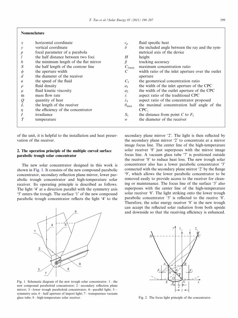
The new solar concentrator designed in this work isshown in Fig. 1. It consists of the new compound parabolicconcentrator, secondary reflection plane mirror, lower par-abolic trough concentrator and high-temperature solarreceiver. Its operating principle is described as follows.The light ‘4’ at a direction parallel with the symmetry axis‘5’ enters the trough. The surface ‘1’ of the new compoundparabolic trough concentrator reflects the light ‘4’ to the
2
1
4 5
6
73 8
9
Fig. 1. Schematic diagram of the new trough solar concentrator. 1—thenew compound paraboloid concentrator; 2—secondary reflection planemirror; 3—lower trough paraboloid concentrator; 4—parallel light; 5—symmetry axis; 6—half aperture of import light; 7—transparence vacuumglass tube; 8—high-temperature solar receiver.
secondary plane mirror ‘2’. The light is then reflected bythe secondary plane mirror ‘2’ to concentrate at a mirrorimage focus line. The center line of the high-temperaturesolar receiver ‘8’ just superposes with the mirror imagefocus line. A vacuum glass tube ‘7’ is positioned outsidethe receiver ‘8’ to reduce heat loss. The new trough solarconcentrator also has a lower parabolic concentrator ‘3’connected with the secondary plane mirror ‘2’ by the flange‘9’, which allows the lower parabolic concentrator to beremoved easily to provide access to the receiver for clean-ing or maintenance. The focus line of the surface ‘3’ alsosuperposes with the center line of the high-temperaturesolar receiver ‘8’. The light striking onto the lower troughparabolic concentrator ‘3’ is reflected to the receive ‘8’.Therefore, the solar energy receiver ‘8’ in the new troughcan accept the reflected solar radiation from both upsideand downside so that the receiving efficiency is enhanced.
l
l2
A B
CD
E GO
F1 F2
y
x
FN
1 2
P
Fig. 2. The focus light principle of the concentrator.
200 T. Tao et al. / Solar Energy 85 (2011) 198–207
The reflected solar radiation is absorbed on the receiver toheat the working medium inside. Finally, the high-temper-ature thermal energy is converted to useful energy throughthe working medium.
3. The design method of the multiple curved surface parabolictrough solar concentrator
Fig. 2 shows the sectional diagram of the new concentra-tor. The x–y coordinate system is established as shown inFig. 2. Curve DA and CB respectively is the section oftwo parabolic curves with same size and aperture upturned.F1 and F2 respectively are two focus points of the paraboliccurves. Equations of the parabolic curves can be given by:
y ¼ 1
2pðxþ lÞ2 ð1Þ
y ¼ 1
2pðx� lÞ2 ð2Þ
where p is the focus parameter (equal to twice the nominalfocal length OF in Fig. 2), l is the level distance between fo-cus point F1 and y axis. Make beeline AB parallel with x
axis and cut the parabolic curves and order,jABj ¼ jF 1F 2j
2¼ l. Linear segment AE and BG are parallel
with the y axis, respectively. The reasonable length of AEand BG is the width of the secondary reflection plane mir-ror. In order to make the sunlight directly radiatingthrough linear segment AB to be reflected again to the re-ceiver, another parabolic curve EPG is designed as lowertrough parabolic concentrator. Its focus line also super-poses with the center line of the high-temperature solar re-ceiver. And then, all reflection surfaces are obtainedtogether with parabolic curve segment DA and CB, linearsegment AE and BG, and parabolic curve segment EPG.This new multiple curved surface parabolic trough solarconcentrator is just these segments translated along theorthogonal z direction.
0 2 4 6 8 10 12 14 160
10
20
30
40
50
60
p = 3
p = 1.5
plan
e m
irro
r he
ight
(h)
outlet aperture width (l)
p = 2
Fig. 3. The variation of the minimum height of the plane mirror withwidth l.
3.1. The distance of two parabolic curve focus points
It is noticeable that the light exit width l of the new com-pound parabolic trough concentrator must satisfy a condi-tion, namely bigger than a numerical value (Kaiyan et al.,2007). The value can be determined as follows:
In Fig. 2, the Y coordinate of point B can be obtained byEq. (1),
Y B ¼1
2pðxB þ lÞ2 ¼ 1
2pl2þ l
� �2
¼ 9l2
8pð3Þ
The Y coordinate of point B should be greater than thatof its focal point, p/2. It must be Y B > p=2.
Therefore,
9l2
8p>
p2
ð4Þ
So l > 2=3p; 0 < p <1. Also, it requires the distance oftwo parabolic curve focus points jF 1F 2j > 4=3p. Due to l, p
being positive, then 0 < p=l < 3=2.
3.2. The minimum height of the secondary reflection plane
mirror
It can be seen from Fig. 2 that light “1” is reflected byparabolic curve segment CB to point N on the plane mirrorAE. Relative to other reflective points, the point N is low-est. So, the minimum height of the secondary reflectionplane mirror should be the length of AN. Position of pointN can be determined by the point of intersection of line seg-ment BF1 and AE (Kaiyan et al., 2007).
The equation of beeline BF1 is,
y � yF 1
x� xF 1
¼yF 1� yB
xF 1� xB
ð5Þ
y � p2
x� l¼
p2� 9l2
8p
lþ l2
ð6Þ
Coordinate Eq. (6) to get,
y ¼ 3l4p� p
3l
� �xþ 3l2
4pþ p
6ð7Þ
Also, the equation of beeline AE is x ¼ �l=2.And then, the intersection point coordinates of beeline
BF1 and AE is given by:
yN ¼3l4p� p
3l
� �� l
2
� �þ 3l2
4pþ p
6¼ 3l2
8pþ p
3ð8Þ
Therefore, the minimum height of the secondary reflec-tion plane mirror should be,
jAN j > h ¼ yA � yN ¼9l2
8p� 3l2
8p� p
3¼ 3l2
4p� p
3ð9Þ
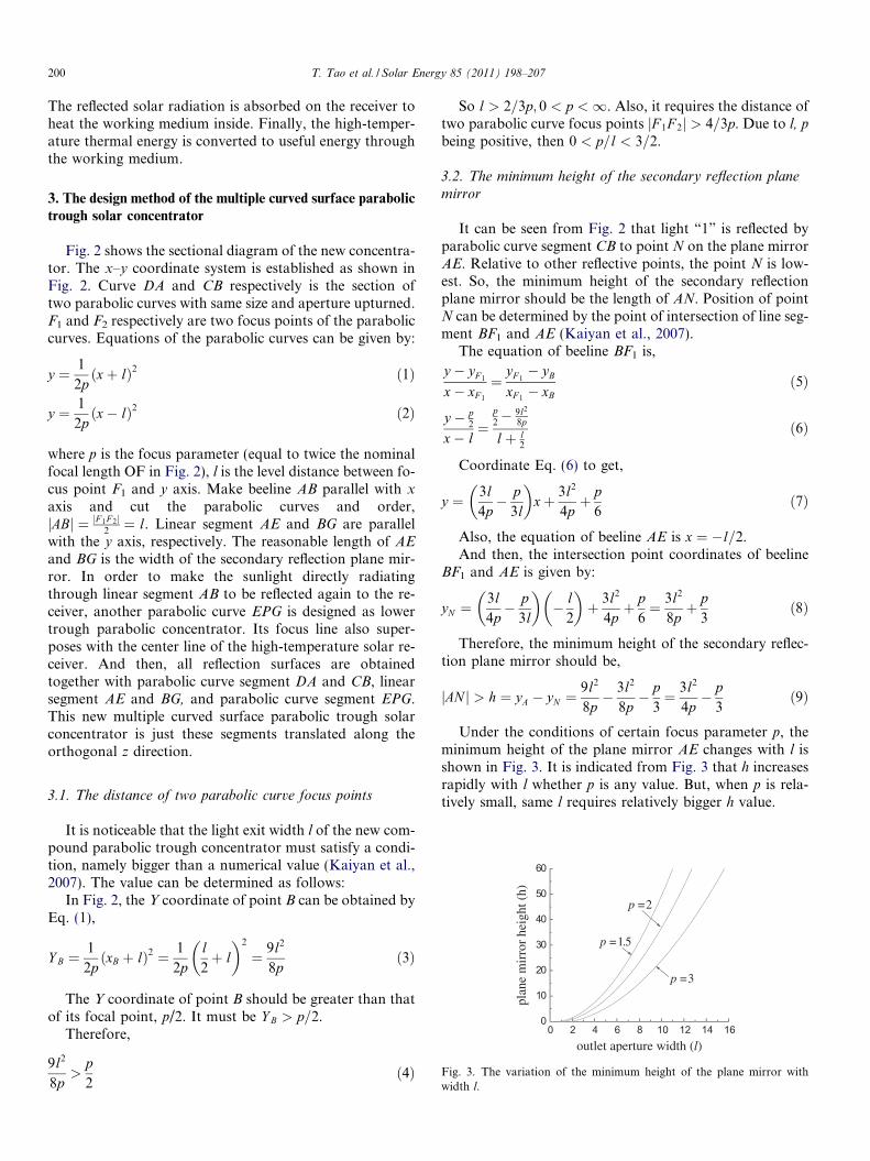
Under the conditions of certain focus parameter p, theminimum height of the plane mirror AE changes with l isshown in Fig. 3. It is indicated from Fig. 3 that h increasesrapidly with l whether p is any value. But, when p is rela-tively small, same l requires relatively bigger h value.
0 2 4 6 8 10 12 14 16 18 200
20
40
60
80
100
120
conventional concentrator,p=2
l=8.5;p=2
mat
eria
l len
gth
(S)
half of inlet aperture width (xc)
l=4.25;p=2
Fig. 4. The variation of the half length of the collector with width xC.
0 2 4 6 8 10 12 14 16 18 20102030405060708090
100
mat
eria
l len
gth
(S)
outlet aperturewidth (l)
xc=10;p=2 xc=8.5;p=2
xc=6;p=2
Fig. 5. The variation of the material length with width l.
0 2 4 6 8 10 12 14 16 18 20 22 240
102030405060708090
100
xc=7;l=4
mat
eria
l len
gth
(S)
focus parameter (p)
xc=8;l=6
Fig. 6. The variation of the material length with focus parameter.
T. Tao et al. / Solar Energy 85 (2011) 198–207 201
3.3. The design of lower parabolic trough concentrator
It is known that the focus point of lower parabolictrough concentrator is also in mirror image point F. Andthen, its parabolic curve equation in x–y axis system shouldhave same focus parameter p. In this case, the paraboliccurve equation may have different variations. One of themis to order the parabolic curve pass through point N. In thiscase, the equation can be obtained as follows:
y ¼ 3x2
2pþ p
3ð10Þ
Certainly, different parabolic curve equations can alsobe selected for other causations.
4. The structural parameters and optimization of the system
4.1. The relation between the quantity of reflector material
and focus parameters, the light exit and import width
For the cross sectional structural diagram shown inFig. 2, the total quantity of reflector material of the systemis the addition of all reflection surfaces which are repre-sented by line segment DA, AE, EG, BG and BC. Undercertain conditions, in order to reduce quantity of the mate-rial used, one must select the relative parameters so as tominimize the length of total reflection line. Therefore, eachline segment length is calculated as follows:
jBCj ¼Z xC
l2
ffiffiffiffiffiffiffiffiffiffiffiffiffiffiffiffiffiffiffiffiffiffiffiffiffiffiffi1þ xþ l
p
� �2s
dx
¼ xC þ l2
ffiffiffiffiffiffiffiffiffiffiffiffiffiffiffiffiffiffiffiffiffiffiffiffiffiffiffiffiffiffi1þ xC þ l
p
� �2s
þ p2
lnxC þ l
pþ
ffiffiffiffiffiffiffiffiffiffiffiffiffiffiffiffiffiffiffiffiffiffiffiffiffiffiffiffiffiffi1þ xC þ l
p
� �2s0
@1A
� 3l4
ffiffiffiffiffiffiffiffiffiffiffiffiffiffiffiffiffiffiffiffiffiffi1þ 3l
2p
� �2s
� p2
ln3l2pþ
ffiffiffiffiffiffiffiffiffiffiffiffiffiffiffiffiffiffiffiffiffiffi1þ 3l
2p
� �2s0
@1Að11Þ
According to Eq. (9), the minimum height of the second-ary reflection plane mirror AE or BG is jAEj ¼ 3l2
4p �p3.
Due to the width of lower parabolic trough concentratorbeing relatively small, the parabolic segment length isapproximately considered to be l. Then, the total halflength of the collector is,
S ¼ jBCj þ jAEj þ l2¼ l
2þ 3l2
4p� p
3þ jBCj ð12Þ
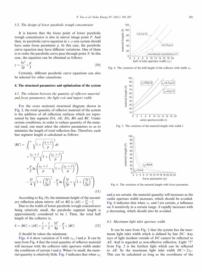
S should be taken the minimum.Figs. 4–6 show variation of S with xC, l and p. It can be
seen from Fig. 4 that the total quantity of reflector materialwill increase with the collector inlet aperture width underthe conditions of certain l and p. When l is small, the mate-rial quantity is relatively little. Fig. 5 indicates that when xC
and p are certain, the material quantity will increases as theoutlet aperture width increases, which should be avoided.Fig. 6 indicates that when xC and l are certain, p influenceon S sensitively in a certain range. S rapidly increases withp decreasing, which should also be avoided.
4.2. Maximum light inlet aperture width
It can be seen from Fig. 2 that the system has the max-imum light inlet width which is defined by line DC. Anyrays of light incident outside of DC cannot be reflected toAE. And is regarded as non-effective reflection. Light “2”
from Fig. 2 is the farthest light which can be reflectedto AE. So the maximum light inlet width DC = 2xC.This can be calculated as long as the coordinate of the
202 T. Tao et al. / Solar Energy 85 (2011) 198–207
intersection point C between the beeline F1A and paraboliccurve segment CB can be determined.
The coordinate of point A is known:
xA ¼ �l2
ð13Þ
yA ¼1
2pðxA � lÞ2 ¼ 1
2p� l
2� l
� �2
¼ 9l2
8pð14Þ
The coordinate of point F1 is known:
xF 1¼ �l; yF 1
¼ p2
ð15Þ
Straight line equation through point A and F1 is,y � yF 1
x� xF 1
¼yA � yF 1
xA � xF 1
So,
y � p2
xþ l¼
9l2
8p �p2
� l2þ l
Adjust the equation to get,
y ¼ 9l4p� p
l
� �xþ 9l2
4p� p
2ð16Þ
The coordinates of intersection point C satisfy the equa-tion group:
yC ¼ 9l4p �
pl
� �xC þ 9l2
4p �p2
yC ¼ 12p ðxC þ lÞ2
8<: ð17Þ
Solve above equations simultaneously,
xC ¼5l4� p2
lþ
ffiffiffiffiffiffiffiffiffiffiffiffiffiffiffiffiffiffiffiffiffiffiffiffiffiffiffiffiffiffiffiffiffiffi9l4� p2
l
� �2
þ p2
sð18Þ
yC ¼1
2pðxC þ lÞ2 ¼ 1
2p9l4� p2
lþ
ffiffiffiffiffiffiffiffiffiffiffiffiffiffiffiffiffiffiffiffiffiffiffiffiffiffiffiffiffiffiffiffiffiffi9l4� p2
l
� �2
þ p2
s0@
1A
2
ð19Þ
Therefore, the maximum inlet width is,
/ ¼ 2xC ¼ 2l5
4� p2
l2þ
ffiffiffiffiffiffiffiffiffiffiffiffiffiffiffiffiffiffiffiffiffiffiffiffiffiffiffiffiffiffiffiffi9
4� p2
l2
� �2
þ p2
l2
s0@
1A ð20Þ
1 2 3 4 5 6048
1216202428323640
p=3
the
max
imum
inle
t wid
th (
)
outlet aperture width (l)
p =2
p=1.5
Fig. 7. The outlet width influence on the inlet width.
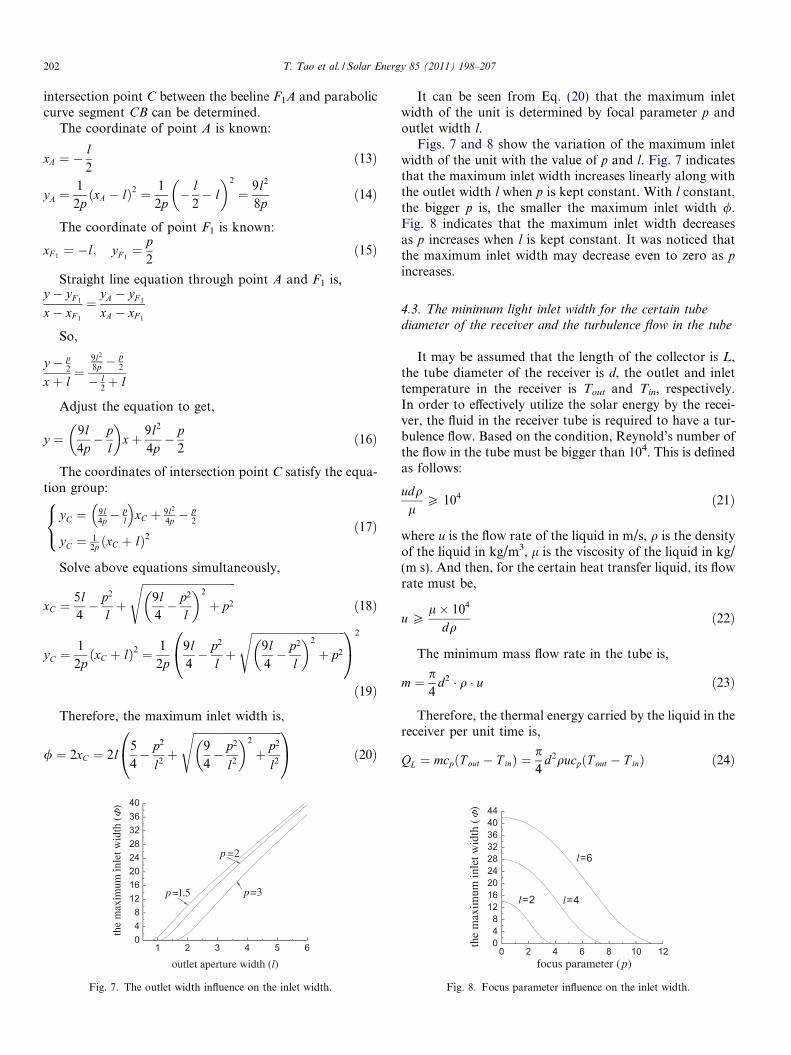
It can be seen from Eq. (20) that the maximum inletwidth of the unit is determined by focal parameter p andoutlet width l.
Figs. 7 and 8 show the variation of the maximum inletwidth of the unit with the value of p and l. Fig. 7 indicatesthat the maximum inlet width increases linearly along withthe outlet width l when p is kept constant. With l constant,the bigger p is, the smaller the maximum inlet width /.Fig. 8 indicates that the maximum inlet width decreasesas p increases when l is kept constant. It was noticed thatthe maximum inlet width may decrease even to zero as p
increases.
4.3. The minimum light inlet width for the certain tubediameter of the receiver and the turbulence flow in the tube
It may be assumed that the length of the collector is L,the tube diameter of the receiver is d, the outlet and inlettemperature in the receiver is Tout and Tin, respectively.In order to effectively utilize the solar energy by the recei-ver, the fluid in the receiver tube is required to have a tur-bulence flow. Based on the condition, Reynold’s number ofthe flow in the tube must be bigger than 104. This is definedas follows:
udql
P 104 ð21Þ
where u is the flow rate of the liquid in m/s, q is the densityof the liquid in kg/m3, l is the viscosity of the liquid in kg/(m s). And then, for the certain heat transfer liquid, its flowrate must be,
u Pl� 104
dqð22Þ
The minimum mass flow rate in the tube is,
m ¼ p4
d2 � q � u ð23Þ
Therefore, the thermal energy carried by the liquid in thereceiver per unit time is,
QL ¼ mcpðT out � T inÞ ¼p4
d2qucpðT out � T inÞ ð24Þ
0 2 4 6 8 10 12048
121620242832364044
the
max
imum
inle
t wid
th (
)
focus parameter (p)
l=4
l=6
l=2
Fig. 8. Focus parameter influence on the inlet width.

1 2 3 4
F
1'2' 3'
4'
Fig. 9. The path of marginal rays in deal concentrator.
T. Tao et al. / Solar Energy 85 (2011) 198–207 203
For a system with maximum light inlet half-width xC
and length L, the total solar energy irradiating into systemin unit time is 2LxCI. Where I is solar irradiation. If theefficiency of the system is g, the total energy irradiatingon the receiver tube and absorbed by the liquid in tube is,
QI ¼ 2LxCIg
According to law of conservation of energy, QL = QI
hence,
xC ¼pd2qcpuðT out � T inÞ
8LIgð25Þ
In order to achieve a turbulence flow in the tube, theminimum collector half-width is required as follows:
xC min ¼pdcplðT out � T inÞ � 104
8LIgð26Þ
It can be seen that the minimum collector half-width isdependent upon cp and l of the liquid in receiver tubeand as well the size of the system and receiver. The longerthe length of the system, the less the minimum collectorwidth is required. The stronger solar radiation received,the higher the efficiency of the system and hence the lessthe minimum collector width is required. At the same time,in order to reduce the size of the concentrator, it must benoticed that d should be taken relatively small valuebecause it is proportional to xCmin. A more precise trackingunit will be required if d takes a relatively small value.Therefore, in order to retain the small inner diameter, d,of the tube a finned tube is frequently used in practicalapplications. For example, d should be less than11.4 mm, when xC = 0.35 m, L = 4 m, Tout = 76 �C,Tin = 70 �C, I = 800 W/m2, g = 40% (most of parameterscome from one of our experiments, in this example, d istaken 10 mm).
4.4. The structure and shape of the receiver and minimal
tolerance tracking error
The minimum tracking accuracy of the system can bedetermined by analyzing the incident ray at the extremeedge of the concentrator aperture. Assuming C to be apoint on the edge of the inlet, the light striking at C isreflected twice to F. According to the principle of mirrorimage, the distance of light traveling from C to F is equalto the length of CF1. In order to determine the minimumtracking accuracy of the system, the receiver can beassumed to be placed at the F1. In this case, its limitationto the deflection angle of the light from C is the same asthat in F. Theoretically, if the system perfectly tracks thesun, the light coming from C should strike on the centerof the receiver. However, in reality, taking into accountthe tracking error, there is deflection angle between sym-metrical axes of the system and sunlight. The maximumtolerance of this deflection angle is equal to the minimumtracking accuracy required by the system. If the maximumtolerance of deflection angle between symmetrical axes of
the system and sunlight is b, then b relative to C is the min-imum tracking accuracy required by the system. The valueof b is determined by the receiver’s diameter and the lengthof the straight segment CF1. By parabolic equation and thegiven value of l, the length of CF1 can be obtained asfollows:
CF 1 ¼ffiffiffiffiffiffiffiffiffiffiffiffiffiffiffiffiffiffiffiffiffiffiffiffiffiffiffiffiffiffiffiffiffiffiffiffiffiffiffiffiffiffiffiffiðxC þ lÞ2 þ yC �
p2
� �2r
¼
ffiffiffiffiffiffiffiffiffiffiffiffiffiffiffiffiffiffiffiffiffiffiffiffiffiffiffiffiffiffiffiffiffiffiffiffiffiffiffiffiffiffiffiffiffiffiffiffiffiffiffiffiffiffiffiffiffiffiffiffiffiffiffiffiðxC þ lÞ2 þ 1
2pðxC þ lÞ2 � p
2
� �2s
ð27Þ
Assume the receiver is round tube with diameter d.According to the geometry relation the minimum trackingaccuracy of the system can be calculated as follows:
b ¼ arcsind
2ðCF 1Þ� 1
2
dðCF 1Þ
180
pð�Þ ð28Þ
It indicates that tracking accuracy requirement is closelyrelated to the diameter of the receiver and the size of thesystem. When the diameter of the receiver increases thetracking accuracy demand can be decrease effectively. Forexample, when xC = 0.7 m, l = 0.35 m, p = 0.1647 m, thenfor point C, bC = 0.78�. Using the same condition, thetracking accuracy requirement for point B was found tobe bB = 2.46�. It shows that on the parabolic surface thetracking accuracy requirement for different points is notthe same.
4.5. Influence of convergence angle and of incidence angle of
direct sunlight on the concentrator
Theoretically, the concentrator has a ideal focusing effectfor parallel light, however, there is a convergence angle(4.6 mrad) when direct sunlight reach the earth. Therefore,the running state of converging light in the concentratorshould be studied. As shown in Fig. 9, assume the concen-trator is deal one incident rays are parallel light and the
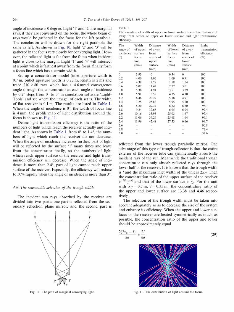
Table 1The variation of width of upper or lower surface focus line, distance ofaway from center of upper or lower surface and light transmissionefficiency.
Theangle ofincidence(�)
Widthof uppersurfacefocusline(mm)
Distanceof awayfromcenter ofuppersurface(mm)
Widthof lowersurfacefocusline(mm)
Distanceof awayfromcenter oflowersurface(mm)
Lighttransmissionefficiency(%)
0 3.93 0 0.34 0 1000.2 4.00 4.06 1.09 0.91 1000.4 4.38 7.78 1.58 1.54 1000.6 5.02 11.42 2.77 3.01 1000.8 5.36 14.94 3.51 3.29 1001.0 5.91 18.59 4.35 4.10 1001.2 6.46 22.29 5.18 4.91 1001.4 7.25 25.83 5.95 5.70 1001.6 8.20 29.34 6.32 6.30 98.71.8 9.24 32.68 6.95 6.94 97.42.0 10.16 35.98 25.03 1.67 97.42.2 11.06 39.26 25.68 1.64 96.12.4 11.96 42.48 27.53 0.66 94.72.6 – – – – 90.82.8 – – – – 72.43.0 – – – – 52.6
204 T. Tao et al. / Solar Energy 85 (2011) 198–207
angle of incidence is 0 degree. Light ‘1’ and ‘2’ are marginalrays, if they are converged on the focus, the whole beam ofrays would be gathered in the focus for the left parabola.The conclusion will be drawn for the right parabola thesame as left. As shown in Fig. 10, light ‘2’ and ‘3’ will begathered in the focus very closely for converging light. How-ever, the reflected light is far from the focus when incidentlight is close to the margin. Light ‘1’ and ‘4’ will intersectat a point which is farthest away from the focus, finally forma focus line which has a certain width.
Set up a concentrator model (inlet aperture width is0.7 m, outlet aperture width is 0.23 m, length is 2 m) andtrace 210 � 80 rays which has a 4.6 mrad convergenceangle through the concentrator at each angle of incidenceby 0.2� steps from 0� to 3� in simulation software ‘Light-Tools’ and see where the ‘image’ of each set is. The widthof flat receiver is 0.1 m. The results are listed in Table 1.When the angle of incidence is 0�, the width of focus lineis 4 mm, the profile map of light distribution around thefocus is shown as Fig. 11.
Define light transmission efficiency is the ratio of thenumbers of light which reach the receiver actually and inci-dent light. As shown in Table 1, from 0� to 1.4�, the num-bers of light which reach the receiver do not decrease.When the angle of incidence increases further, part of lightwill be reflected by the surface ‘1’ many times and leavefrom the concentrator finally, so the numbers of lightwhich reach upper surface of the receiver and light trans-mission efficiency will decrease. When the angle of inci-dence is more than 2.4�, part of light cannot reach uppersurface of the receiver. Especially, the efficiency will reduceto 50% rapidly when the angle of incidence is more than 3�.
4.6. The reasonable selection of the trough width
The incident sun rays absorbed by the receiver aredivided into two parts: one part is reflected from the sec-ondary reflection plane mirror, and the second part is
1 2 3 4
F
1'2' 3'
4'
Fig. 10. The path of marginal converging light.
reflected from the lower trough parabolic mirror. Oneadvantage of this type of trough collector is that the entireexterior of the receiver tube can symmetrically absorb theincident rays of the sun. Meanwhile the traditional troughconcentrator can only absorb reflected rays through thelower half of the receiver. It is known that the trough widthis l and the maximum inlet width of the unit is 2xC. Thenthe concentration ratio of the upper surface of the receiveris 2ð2xC�lÞ
pd and that of the lower surface is 2lpd. For the unit
with xC = 0.7 m, l = 0.35 m, the concentrating ratio ofthe upper and lower surface are 13.38 and 4.46 respec-tively.
The selection of the trough width must be taken intoaccount adequately so as to decrease the size of the systemand enhance its efficiency. When the upper and lower sur-faces of the receiver are heated symmetrically as much aspossible, the concentration ratio of the upper and lowershould be approximately equal.
2ð2xC � lÞpd
� 2lpd
ð29Þ
Fig. 11. The distribution of light around the focus.
T. Tao et al. / Solar Energy 85 (2011) 198–207 205
Thus it can be calculated and given xC � l. Of course, inorder to enhance the material use efficiency of the system,the value of xC should be bigger than l.
5. The comparison with the traditional trough CPC
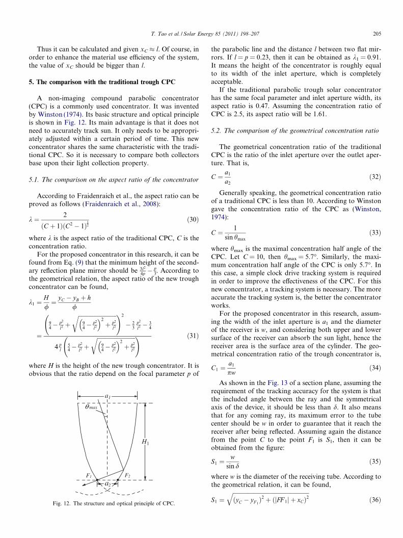
A non-imaging compound parabolic concentrator(CPC) is a commonly used concentrator. It was inventedby Winston (1974). Its basic structure and optical principleis shown in Fig. 12. Its main advantage is that it does notneed to accurately track sun. It only needs to be appropri-ately adjusted within a certain period of time. This newconcentrator shares the same characteristic with the tradi-tional CPC. So it is necessary to compare both collectorsbase upon their light collection property.
5.1. The comparison on the aspect ratio of the concentrator
According to Fraidenraich et al., the aspect ratio can beproved as follows (Fraidenraich et al., 2008):
k ¼ 2
ðC þ 1ÞðC2 � 1Þ12
ð30Þ
where k is the aspect ratio of the traditional CPC, C is theconcentration ratio.
For the proposed concentrator in this research, it can befound from Eq. (9) that the minimum height of the second-ary reflection plane mirror should be 3l2
4p �p3. According to
the geometrical relation, the aspect ratio of the new troughconcentrator can be found,
k1 ¼H/¼ yC � yB þ h
/
¼
94� p2
l2 þffiffiffiffiffiffiffiffiffiffiffiffiffiffiffiffiffiffiffiffiffiffiffiffiffiffiffi
94� p2
l2
� �2
þ p2
l2
r !2
� 23
p2
l2 � 34
4 pl
54� p2
l2 þffiffiffiffiffiffiffiffiffiffiffiffiffiffiffiffiffiffiffiffiffiffiffiffiffiffiffi
94� p2
l2
� �2
þ p2
l2
r ! ð31Þ
where H is the height of the new trough concentrator. It isobvious that the ratio depend on the focal parameter p of
F1 F2
θ max
a1
a2
H1
Fig. 12. The structure and optical principle of CPC.
the parabolic line and the distance l between two flat mir-rors. If l = p = 0.23, then it can be obtained as k1 = 0.91.It means the height of the concentrator is roughly equalto its width of the inlet aperture, which is completelyacceptable.
If the traditional parabolic trough solar concentratorhas the same focal parameter and inlet aperture width, itsaspect ratio is 0.47. Assuming the concentration ratio ofCPC is 2.5, its aspect ratio will be 1.61.
5.2. The comparison of the geometrical concentration ratio
The geometrical concentration ratio of the traditionalCPC is the ratio of the inlet aperture over the outlet aper-ture. That is,
C ¼ a1
a2
ð32Þ
Generally speaking, the geometrical concentration ratioof a traditional CPC is less than 10. According to Winstongave the concentration ratio of the CPC as (Winston,1974):
C ¼ 1
sin hmax
ð33Þ
where hmax is the maximal concentration half angle of theCPC. Let C = 10, then hmax = 5.7�. Similarly, the maxi-mum concentration half angle of the CPC is only 5.7�. Inthis case, a simple clock drive tracking system is requiredin order to improve the effectiveness of the CPC. For thisnew concentrator, a tracking system is necessary. The moreaccurate the tracking system is, the better the concentratorworks.
For the proposed concentrator in this research, assum-ing the width of the inlet aperture is a1 and the diameterof the receiver is w, and considering both upper and lowersurface of the receiver can absorb the sun light, hence thereceiver area is the surface area of the cylinder. The geo-metrical concentration ratio of the trough concentrator is,
C1 ¼a1
pwð34Þ
As shown in the Fig. 13 of a section plane, assuming therequirement of the tracking accuracy for the system is thatthe included angle between the ray and the symmetricalaxis of the device, it should be less than d. It also meansthat for any coming ray, its maximum error to the tubecenter should be w in order to guarantee that it reach thereceiver after being reflected. Assuming again the distancefrom the point C to the point F1 is S1, then it can beobtained from the figure:
S1 ¼w
sin dð35Þ
where w is the diameter of the receiving tube. According tothe geometrical relation, it can be found,
S1 ¼ffiffiffiffiffiffiffiffiffiffiffiffiffiffiffiffiffiffiffiffiffiffiffiffiffiffiffiffiffiffiffiffiffiffiffiffiffiffiffiffiffiffiffiffiffiffiffiffiffiffiffiffiffiffiðyC � yF 1
Þ2 þ ðjFF 1j þ xCÞ2q
ð36Þ
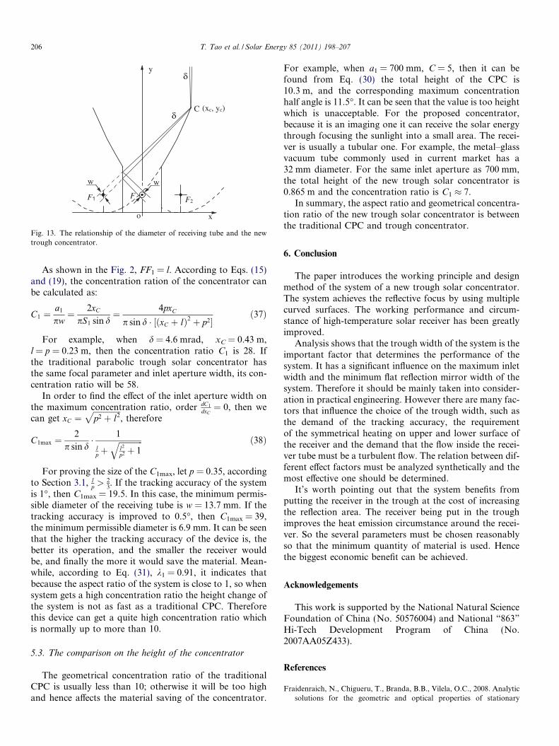
F1 F
w
F2
(xc, yc)
y
x
w
C
o
δ
δ
Fig. 13. The relationship of the diameter of receiving tube and the newtrough concentrator.
206 T. Tao et al. / Solar Energy 85 (2011) 198–207
As shown in the Fig. 2, FF1 = l. According to Eqs. (15)and (19), the concentration ration of the concentrator canbe calculated as:
C1 ¼a1
pw¼ 2xC
pS1 sin d¼ 4pxC
p sin d � ½ðxC þ lÞ2 þ p2�ð37Þ
For example, when d = 4.6 mrad, xC = 0.43 m,l = p = 0.23 m, then the concentration ratio C1 is 28. Ifthe traditional parabolic trough solar concentrator hasthe same focal parameter and inlet aperture width, its con-centration ratio will be 58.
In order to find the effect of the inlet aperture width onthe maximum concentration ratio, order dC1
dxC¼ 0, then we
can get xC ¼ffiffiffiffiffiffiffiffiffiffiffiffiffiffip2 þ l2
p, therefore
C1max ¼2
p sin d� 1
lp þ
ffiffiffiffiffiffiffiffiffiffiffiffil2
p2 þ 1q ð38Þ
For proving the size of the C1max, let p = 0.35, accordingto Section 3.1, l
p >23. If the tracking accuracy of the system
is 1�, then C1max = 19.5. In this case, the minimum permis-sible diameter of the receiving tube is w = 13.7 mm. If thetracking accuracy is improved to 0.5�, then C1max = 39,the minimum permissible diameter is 6.9 mm. It can be seenthat the higher the tracking accuracy of the device is, thebetter its operation, and the smaller the receiver wouldbe, and finally the more it would save the material. Mean-while, according to Eq. (31), k1 = 0.91, it indicates thatbecause the aspect ratio of the system is close to 1, so whensystem gets a high concentration ratio the height change ofthe system is not as fast as a traditional CPC. Thereforethis device can get a quite high concentration ratio whichis normally up to more than 10.
5.3. The comparison on the height of the concentrator
The geometrical concentration ratio of the traditionalCPC is usually less than 10; otherwise it will be too highand hence affects the material saving of the concentrator.
For example, when a1 = 700 mm, C = 5, then it can befound from Eq. (30) the total height of the CPC is10.3 m, and the corresponding maximum concentrationhalf angle is 11.5�. It can be seen that the value is too heightwhich is unacceptable. For the proposed concentrator,because it is an imaging one it can receive the solar energythrough focusing the sunlight into a small area. The recei-ver is usually a tubular one. For example, the metal–glassvacuum tube commonly used in current market has a32 mm diameter. For the same inlet aperture as 700 mm,the total height of the new trough solar concentrator is0.865 m and the concentration ratio is C1 � 7.
In summary, the aspect ratio and geometrical concentra-tion ratio of the new trough solar concentrator is betweenthe traditional CPC and trough concentrator.
6. Conclusion
The paper introduces the working principle and designmethod of the system of a new trough solar concentrator.The system achieves the reflective focus by using multiplecurved surfaces. The working performance and circum-stance of high-temperature solar receiver has been greatlyimproved.
Analysis shows that the trough width of the system is theimportant factor that determines the performance of thesystem. It has a significant influence on the maximum inletwidth and the minimum flat reflection mirror width of thesystem. Therefore it should be mainly taken into consider-ation in practical engineering. However there are many fac-tors that influence the choice of the trough width, such asthe demand of the tracking accuracy, the requirementof the symmetrical heating on upper and lower surface ofthe receiver and the demand that the flow inside the recei-ver tube must be a turbulent flow. The relation between dif-ferent effect factors must be analyzed synthetically and themost effective one should be determined.
It’s worth pointing out that the system benefits fromputting the receiver in the trough at the cost of increasingthe reflection area. The receiver being put in the troughimproves the heat emission circumstance around the recei-ver. So the several parameters must be chosen reasonablyso that the minimum quantity of material is used. Hencethe biggest economic benefit can be achieved.
Acknowledgements
This work is supported by the National Natural ScienceFoundation of China (No. 50576004) and National “863”
Hi-Tech Development Program of China (No.2007AA05Z433).
References
Fraidenraich, N., Chigueru, T., Branda, B.B., Vilela, O.C., 2008. Analyticsolutions for the geometric and optical properties of stationary

T. Tao et al. / Solar Energy 85 (2011) 198–207 207
compound parabolic concentrators with fully illuminated inverted Vreceiver. Solar Energy 82, 132–143.
Kaiyan He, Hongfei Zheng, Yixin Liu, Ziqian Chen, 2007. An imagingcompounding parabolic concentrator. In: Proceeding of ISES SolarWorld Congress, vol. 2, pp. 589–592.
Kiatgamolchai, S., Chamni, E., 2008. Theory and experiment of a two-dimensional cone concentrator for sunlight. Solar Energy 82, 111–117.
Murphree, Quincy C., 2001. A point focusing double parabolic troughconcentrator. Solar Energy 70, 85–94.
Price, H., Lupfert, E., Kearney, D., et al., 2002. Advances in parabolictrough solar power technology. Journal of Solar Energy Engineering124 (5), 109–125.
Richter, John L., 1996. Optics of a two-trough solar concentrator. SolarEnergy 56, 191–198.
Schwarzer, Klemens, Eugenia, Maria, Silva, Vieira da, 2008. Character-isation and design methods of solar cookers. Solar Energy 82, 157–163.
Winston, R., 1974. Principles of solar concentrators of a novel design.Solar Energy 16, 89–95.