Embed Size (px)
Citation preview
1
A New Scuffing Test Using Contra-Rotation
Marc Ingram, Clive Hamer and Hugh Spikes
Corresponding author : Marc Ingram; [email protected]
Published; Wear 328-329, 229–240, (2015).
ABSTRACT
The mode of lubricant failure known as scuffing provides a significant design
constraint in high sliding gears, cams and metal cutting and forming processes. It is
therefore important to have an effective test method to measure the scuffing resistance
of lubricant formulations. In most existing scuffing bench tests, a moving surface is
rubbed against a stationary one at a fixed sliding speed and the load at which scuffing
occurs is determined. This approach has two disadvantages. One is that wear of the
stationary surface can lead to a large decrease in effective contact pressure during a
test. The second is that viscous lubricants often generate significant
elastohydrodynamic films at the sliding speeds employed. This means that the
scuffing tests measure a complex combination of the influence of the fluid and
boundary film-forming properties of the lubricant on scuffing rather than reflecting
solely the influence of lubricant formulation.
This paper describes a new scuffing test method in which the two metal surfaces are
rubbed together in mixed rolling-sliding with the two surfaces moving in opposite
directions with respect to the contact, i.e. in contra-rotation. This enables the sliding
speed to be decoupled from the entrainment speed so that the scuffing properties of a
lubricant can be determined in boundary lubrication conditions over a wide range of
sliding speeds. Also, because both surfaces move relative to the contact, wear is
distributed and this minimises changes in contact pressure during a test.
1. BACKGROUND
Scuffing (often termed scoring in the United States) occurs in lubricated contacts
when the lubricating film present in the contact suddenly collapses, resulting in solid-
solid adhesion with a consequent very rapid increase in friction and extensive surface
damage. It occurs in contacts operating at high pressures and sliding speeds and was
first documented in the 1920s when automotive hypoid gears were introduced. This
episode led to the development of extreme pressure additives, initially based on lead,
sulphur and chlorine, specifically designed to prevent scuffing [1]. Scuffing is still a
design barrier in many high-sliding gear configurations, in sliding cam-follower
systems and in metal-cutting and forming processes.
2
Numerous test methods have been designed to determine the conditions at which
scuffing occurs and thus to measure the scuffing resistance of lubricants and materials
and to explore the mechanisms of scuffing. The first scuffing tests such as the four
ball method originated in the 1930s and were developed to address the hypoid gear
scuffing problem and to assist in the development of extreme pressure additives [2].
One important limitation of the four ball test [3] and the more modern Timken test [4]
is that they involve a moving surface rubbing against a stationary counterpart. This
generally results in considerable wear on the stationary surface within the contact,
which leads to a large increase in effective contact area and thus to a considerable
reduction in contact pressure during a test. This means that systems which suffer high
wear often require higher loads to scuff than those which have low wear, a factor that
can obscure their intrinsic scuffing resistance. This limitation was recognised in the
1930s, where it was noted that the SAE Extreme Pressure Machine, a disc machine in
which both surfaces move relative to the contact, gave more useful scuffing
information than tests with one stationary surface [1, 5].
It is important to appreciate that scuffing only takes place when all of the protective
lubricant films that separate the lubricated rubbing surfaces are destroyed by the
rubbing action, i.e. both elastohydrodynamic films due to liquid entrainment and
boundary films resulting from lubricant-surface interactions. The penultimate step
before scuffing is the removal of the metal oxide film, to expose the nascent metal
surface. Since scuffing normally occurs at high sliding speeds, an
elastohydrodynamic (EHD) film is often present and the process of scuffing thus
involves first the collapse of this fluid film, then the loss of any micro-EHD films
present at asperity conjunctions and finally the destruction of any boundary
lubricating films. Any of these three films can provide the critical performance
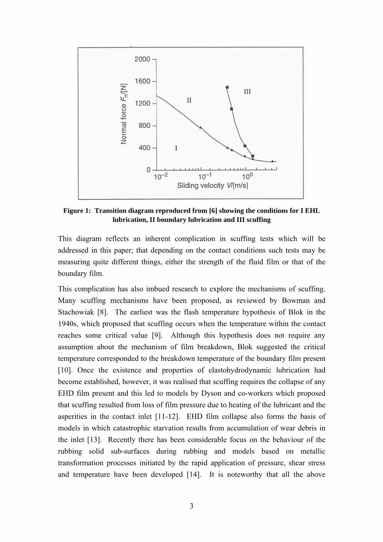
barrier to scuffing. This is reflected in de Gee’s “transition diagram” [6,7], as
illustrated in Figure 1. This maps the scuffing response of a specific lubricated
system in terms of sliding speed and applied load. Three transitions are recognised.
At low sliding speeds (on the left hand side of Figure 1), as the load is increased, first
the EHD (or micro-EHD) film collapses (transition from I to II), generally resulting in
an increase in friction and wear. Scuffing does not occur however, since a boundary
lubricating film is still present. Then as the applied load is increased further, the
boundary film collapses at the transition from II to III and scuffing occurs. At high
sliding speeds, (on the right of Figure 1), as soon as the EHD film collapses the
contact conditions are so severe that any boundary film is also immediately destroyed,
so the system passes straight from EHD lubrication conditions to scuffing, i.e. from I
to III.
3
Figure 1: Transition diagram reproduced from [6] showing the conditions for I EHL lubrication, II boundary lubrication and III scuffing
This diagram reflects an inherent complication in scuffing tests which will be
addressed in this paper; that depending on the contact conditions such tests may be
measuring quite different things, either the strength of the fluid film or that of the
boundary film.
This complication has also imbued research to explore the mechanisms of scuffing.
Many scuffing mechanisms have been proposed, as reviewed by Bowman and
Stachowiak [8]. The earliest was the flash temperature hypothesis of Blok in the
1940s, which proposed that scuffing occurs when the temperature within the contact
reaches some critical value [9]. Although this hypothesis does not require any
assumption about the mechanism of film breakdown, Blok suggested the critical
temperature corresponded to the breakdown temperature of the boundary film present
[10]. Once the existence and properties of elastohydrodynamic lubrication had
become established, however, it was realised that scuffing requires the collapse of any
EHD film present and this led to models by Dyson and co-workers which proposed
that scuffing resulted from loss of film pressure due to heating of the lubricant and the
asperities in the contact inlet [11-12]. EHD film collapse also forms the basis of
models in which catastrophic starvation results from accumulation of wear debris in
the inlet [13]. Recently there has been considerable focus on the behaviour of the
rubbing solid sub-surfaces during rubbing and models based on metallic
transformation processes initiated by the rapid application of pressure, shear stress
and temperature have been developed [14]. It is noteworthy that all the above

4
interpretations of scuffing focus on different stages in the, presumably sequential, film
breakdown process.
The aim of the current paper is not to explore the various proposed scuffing
mechanisms but rather to describe an experimental test approach which should help
both to measure the inherent scuffing-resistance properties of lubricants and to
explore mechanism of scuffing in a systematic fashion. This is timely since engine
lubricants are currently undergoing major formulation changes, driven by
environmental concerns, which involve a reduction in concentrations of the additives
that presently control valve train scuffing. There is also a continuing trend to reduce
the size of engineered components such as gears so as to lower vehicle mass, and this
is resulting in increased contact pressures and thus stronger demands on the lubricant
performance.
2. PRINCIPLE OF TEST METHOD
An often unrecognised problem in scuffing and wear testing is that, when one surface
is stationary and the other moving, as is the case in most scuffing and wear tests, any
increase in sliding speed also leads to a corresponding increase in entrainment speed
and thus EHD film thickness.
If u1 and u2 are the speeds of the two surfaces with respect to the contact, the sliding speed, us is 21 uu and the entrainment, or mean rolling speed, U is 2/21 uu . The
slide roll ratio, SRR, is defined as the ratio of the sliding speed to the entrainment
speed and is thus;
2/21
21
uu
uuSRR
(1)
In a sliding contact with one surface stationary, u2 = 0, so that, from equation 1, the
slide roll ratio has the value 2. Therefore in this type of rubbing contact the
entrainment speed is always half the sliding speed. In elastohydrodynamic
lubrication, the EHD film thickness, h is given by
67.0Ukh (2)
where is the dynamic viscosity [15]. Thus any increase in sliding speed must be
accompanied by a corresponding increase in EHD film thickness, a relationship that
only breaks down when heat generation due to sliding is so great as to reduce the
effective viscosity of the lubricant in the contact inlet.
5
The above means that in most scuffing tests, as the sliding speed is progressively
increased, the thickness (and thus “strength”) of the EHD film also increases, greatly
complicating our interpretation of scuffing results obtained over a range of speeds. It
also means that fluids of higher viscosity will tend to show intrinsically higher
resistance to scuffing than those of lower viscosity, regardless of the presence of
boundary lubricating additives.
One way round this problem was suggested in a little-known paper by Blok in 1946
[16] and is adopted in the current study. He employed a rolling-sliding contact in
which the two rubbing surfaces move in opposite directions relative to the contact, so
that u1 and u2 have opposite signs. This enables the entrainment speed and the sliding
speed to be decoupled so that high sliding speed can be combined with very low
entrainment speed and thus negligible fluid film entrainment. The test thus focuses
entirely on the effectiveness of lubricant additives and boundary films in preventing
scuffing.
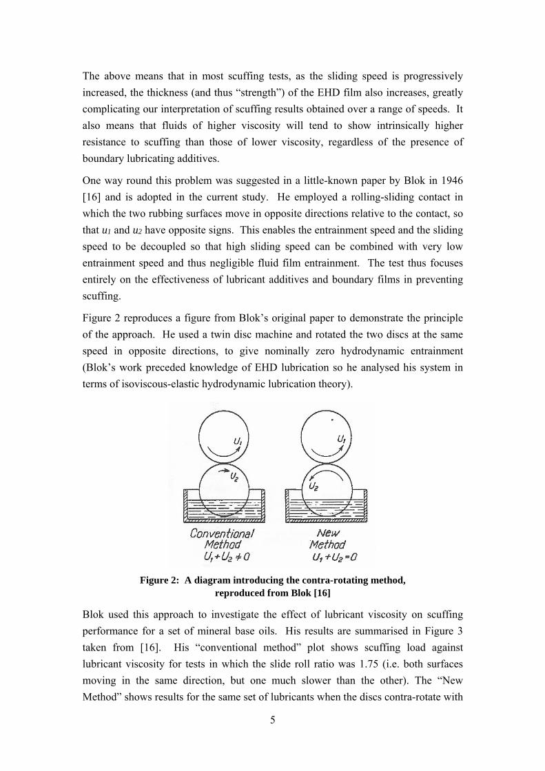
Figure 2 reproduces a figure from Blok’s original paper to demonstrate the principle
of the approach. He used a twin disc machine and rotated the two discs at the same
speed in opposite directions, to give nominally zero hydrodynamic entrainment
(Blok’s work preceded knowledge of EHD lubrication so he analysed his system in
terms of isoviscous-elastic hydrodynamic lubrication theory).
Figure 2: A diagram introducing the contra-rotating method, reproduced from Blok [16]
Blok used this approach to investigate the effect of lubricant viscosity on scuffing
performance for a set of mineral base oils. His results are summarised in Figure 3
taken from [16]. His “conventional method” plot shows scuffing load against
lubricant viscosity for tests in which the slide roll ratio was 1.75 (i.e. both surfaces
moving in the same direction, but one much slower than the other). The “New
Method” shows results for the same set of lubricants when the discs contra-rotate with

6
respect to the contact to give at zero nominal hydrodynamic film thickness. In the
first case there is a marked increase in the load needed to cause scuffing for high
viscosity lubricants, presumably because the EHD film becomes progressively thicker
as viscosity is increased at the constant test speed used. In contra-rotating conditions,
however, the scuffing load increases only slowly and monotonically with viscosity.
Blok ascribed this increase to the higher viscosity minerals oils having larger
proportions of polar, surface active species able to provide boundary film protection.
Figure 3: Load at scuffing failure for a range of mineral oils with varying viscosity reproduced from Blok [16]
It is clear from Blok’s work described above that the use of contra-rotation provides a
simple and elegant means of separating the influence of lubricant formulation on
scuffing from that of lubricant viscosity and it is quite surprising that the approach has
not been widely adopted. The authors could find no later work that has used the same
principle to investigate scuffing, although an alternative way of decoupling
entrainment and sliding speed, by varying the rotational axis of the rotating bodies has
been described by Wedeven [17]. The authors have also recently described the use of
contra-rotation to produce an accelerated mild wear test [18].
3. DETAILS OF TEST METHOD
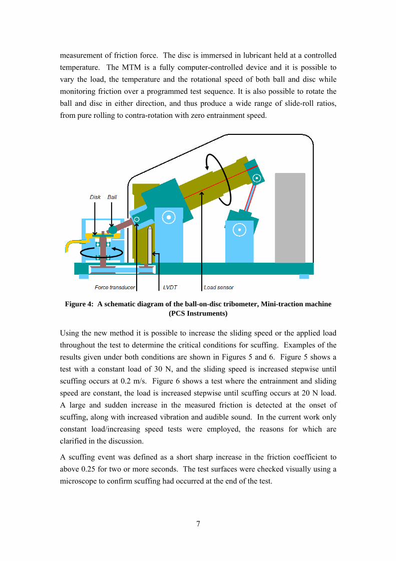
The current study uses a ball-on-disc contact rather than the twin-disc method of
Blok. A mini-traction machine (MTM), manufactured by PCS Instruments is
employed in this study and is shown schematically Figure 4. A ball is loaded and
rotated against the flat surface of a rotating disc, both bodies being driven
independently. The ball shaft is tilted so as to produce nominally zero-spin in the
contact and a load cell is attached to the ball shaft bearing housing to provide a
7
measurement of friction force. The disc is immersed in lubricant held at a controlled
temperature. The MTM is a fully computer-controlled device and it is possible to
vary the load, the temperature and the rotational speed of both ball and disc while
monitoring friction over a programmed test sequence. It is also possible to rotate the
ball and disc in either direction, and thus produce a wide range of slide-roll ratios,
from pure rolling to contra-rotation with zero entrainment speed.
Figure 4: A schematic diagram of the ball-on-disc tribometer, Mini-traction machine (PCS Instruments)
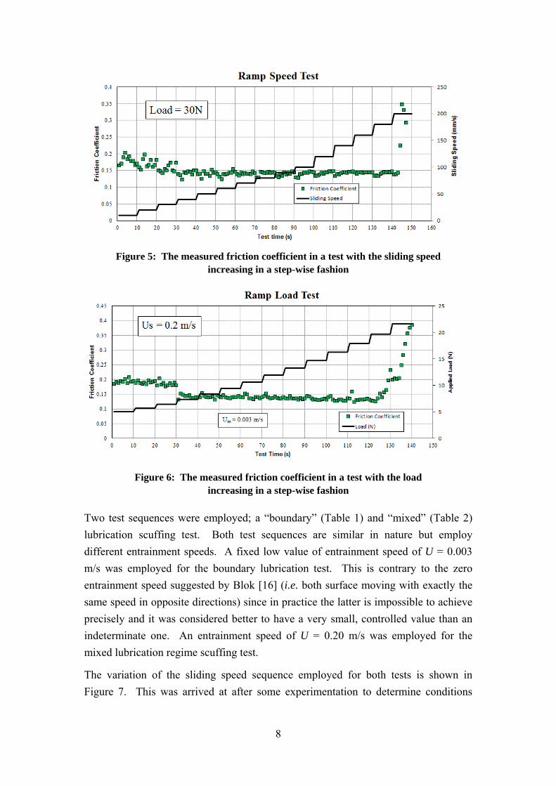
Using the new method it is possible to increase the sliding speed or the applied load
throughout the test to determine the critical conditions for scuffing. Examples of the
results given under both conditions are shown in Figures 5 and 6. Figure 5 shows a
test with a constant load of 30 N, and the sliding speed is increased stepwise until
scuffing occurs at 0.2 m/s. Figure 6 shows a test where the entrainment and sliding
speed are constant, the load is increased stepwise until scuffing occurs at 20 N load.
A large and sudden increase in the measured friction is detected at the onset of
scuffing, along with increased vibration and audible sound. In the current work only
constant load/increasing speed tests were employed, the reasons for which are
clarified in the discussion.
A scuffing event was defined as a short sharp increase in the friction coefficient to
above 0.25 for two or more seconds. The test surfaces were checked visually using a
microscope to confirm scuffing had occurred at the end of the test.
8
Figure 5: The measured friction coefficient in a test with the sliding speed
increasing in a step-wise fashion
Figure 6: The measured friction coefficient in a test with the load
increasing in a step-wise fashion
Two test sequences were employed; a “boundary” (Table 1) and “mixed” (Table 2)
lubrication scuffing test. Both test sequences are similar in nature but employ
different entrainment speeds. A fixed low value of entrainment speed of U = 0.003
m/s was employed for the boundary lubrication test. This is contrary to the zero
entrainment speed suggested by Blok [16] (i.e. both surface moving with exactly the
same speed in opposite directions) since in practice the latter is impossible to achieve
precisely and it was considered better to have a very small, controlled value than an
indeterminate one. An entrainment speed of U = 0.20 m/s was employed for the
mixed lubrication regime scuffing test.
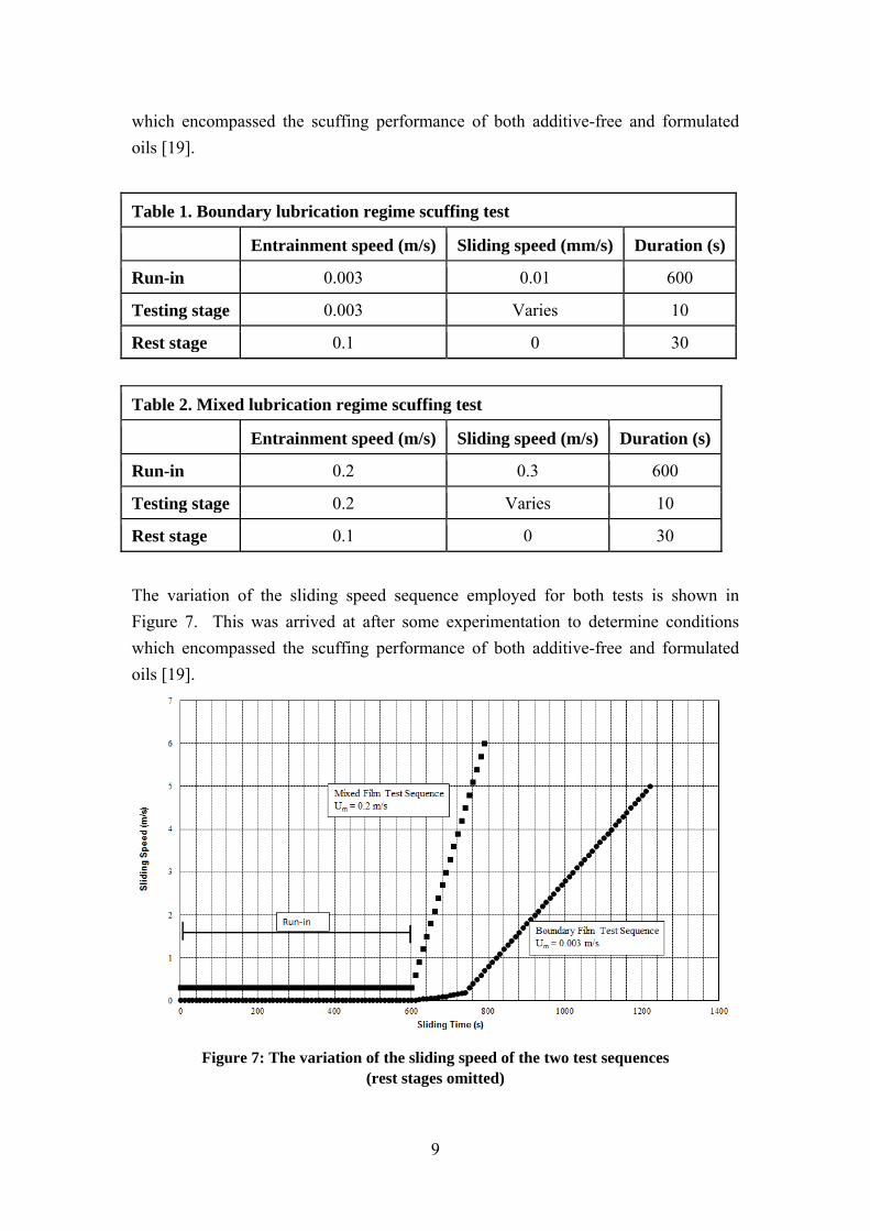
The variation of the sliding speed sequence employed for both tests is shown in
Figure 7. This was arrived at after some experimentation to determine conditions
9
which encompassed the scuffing performance of both additive-free and formulated
oils [19].
Table 1. Boundary lubrication regime scuffing test
Entrainment speed (m/s) Sliding speed (mm/s) Duration (s)
Run-in 0.003 0.01 600
Testing stage 0.003 Varies 10
Rest stage 0.1 0 30
Table 2. Mixed lubrication regime scuffing test
Entrainment speed (m/s) Sliding speed (m/s) Duration (s)
Run-in 0.2 0.3 600
Testing stage 0.2 Varies 10
Rest stage 0.1 0 30
The variation of the sliding speed sequence employed for both tests is shown in
Figure 7. This was arrived at after some experimentation to determine conditions
which encompassed the scuffing performance of both additive-free and formulated
oils [19].
Figure 7: The variation of the sliding speed of the two test sequences (rest stages omitted)
10
A new, freshly-cleaned ball and disc were used for each test. After assembling the
test rig, the temperature was raised to its set value with the ball and disc rotating but
unloaded and then load was applied and 10 minutes run-in carried out at very low
sliding speed. Then the sliding speed was raised in a series of 10 second stages,
separated by 30 seconds, pure rolling stages. The latter were intended to allow
cooling of the test surfaces back to the test temperature (120 °C) after any frictional
heating during the testing stages. The temperature of the lubricant was monitored
during the tests and did not vary more than ± 3 °C. The friction measured during the
rolling stages is omitted in the presentation of the results.
In all tests, balls and disc of AISI 52100 steel were used. The mechanical properties
of these test specimens are given in Table 3.
The MTM can apply a controlled load in the range 1 to 75N ± 0.l N, corresponding to
a maximum Hertz contact pressure range of 0.3 to 1.25 GPa. Table 4 contains the
conversion from applied load to nominal contact pressure for this method, presented
for the reader’s convenience.
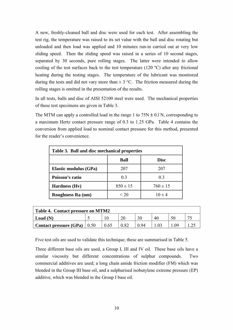
Table 3. Ball and disc mechanical properties
Ball Disc
Elastic modulus (GPa) 207 207
Poisson’s ratio 0.3 0.3
Hardness (Hv) 850 ± 15 760 ± 15
Roughness Ra (nm) < 20 10 ± 4
Table 4. Contact pressure on MTM2
Load (N) 5 10 20 30 40 50 75
Contact pressure (GPa) 0.50 0.65 0.82 0.94 1.03 1.09 1.25
Five test oils are used to validate this technique; these are summarised in Table 5.
Three different base oils are used, a Group I, III and IV oil. These base oils have a
similar viscosity but different concentrations of sulphur compounds. Two
commercial additives are used; a long chain amide friction modifier (FM) which was
blended in the Group III base oil, and a sulphurised isobutylene extreme pressure (EP)
additive, which was blended in the Group I base oil.

11
Table 5. Test lubricant details
Oil Name
Comments Sulphur content
Viscosity 120°C calc. (cP)
Film thickness at Um = 0.003 m/s calc. (nm)
Film thickness at Um = 0.2 m/s calc. (nm)
Group I SN150 base oil
0.25 % wt
3.5 1 13
Group III
Nexbase 3043 < 5 ppm 3.0 1 12
Group IV
PAO 4 ~ 0 2.9 1 12
Group III + FM
Long chain amide
0.5 %wt in Nexbase 3043
< 5 ppm 3.0 1 12
Group I + EP
Sulphurised isobutylene additive in
SN150
1 % wt 3.5 1 13
The data is presented in its entirety, i.e. no test results were excluded as outliers. The
statistical variation is given and investigated in the Discussion section.
4. RESULTS
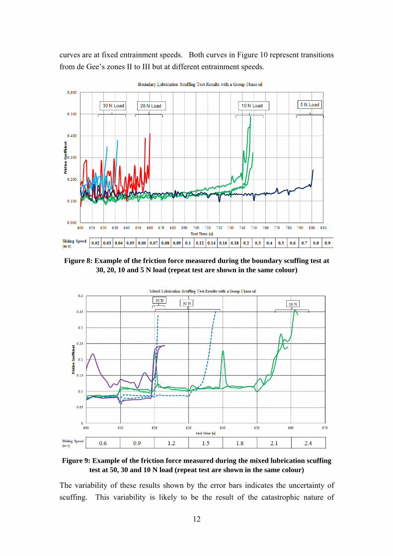
The raw friction values measured during the boundary lubrication scuffing test (U =
0.003 m/s) for the Group I base oil are shown in Figure 8. Example results are shown
for the 30, 20, 10 and 5 N load tests, the lower pressure tests requiring higher sliding
speeds for scuffing to occur. Figure 9 shows the friction measured during the mixed
lubrication scuffing test (U = 0.2) for the same oil at 50, 30 and 10 N load. Scuffing
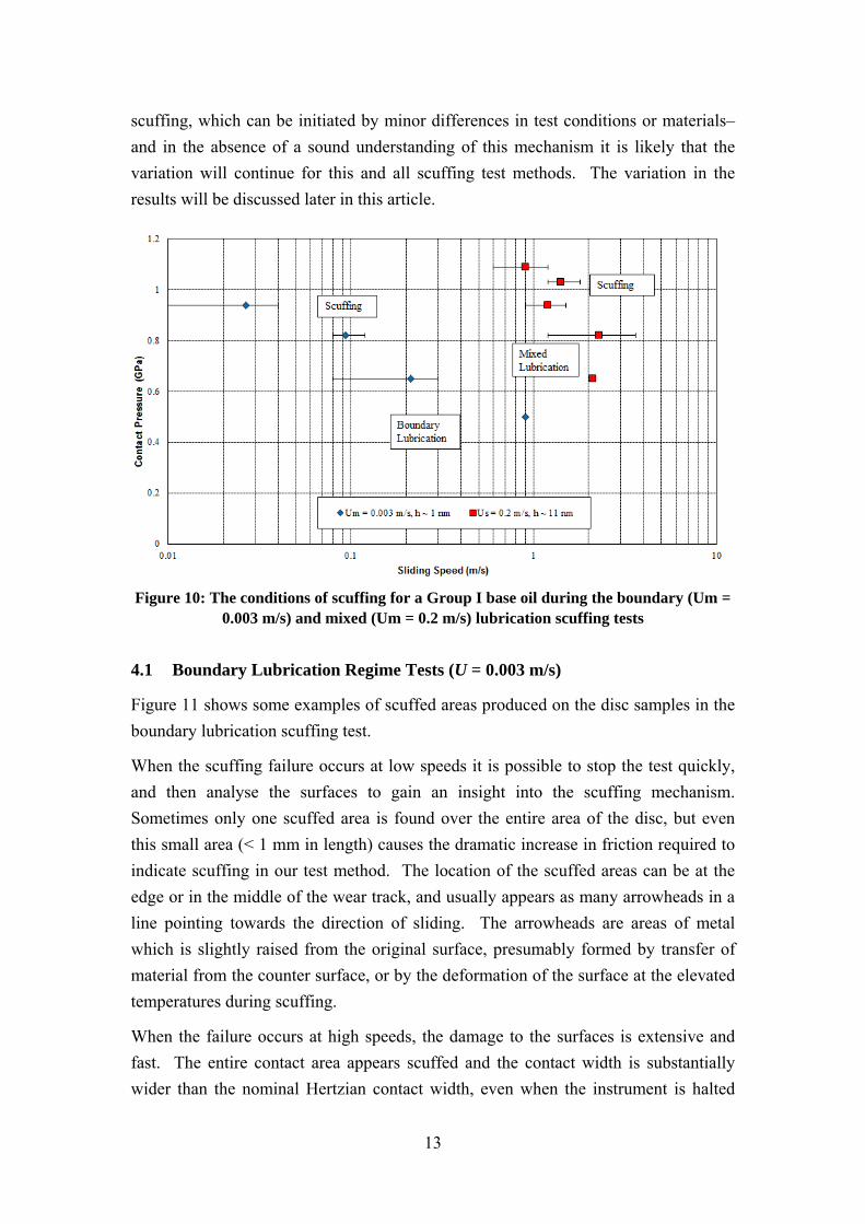
is indicated in both tests by a sudden increase in friction. The conditions (sliding
speed and contact pressure) that induce scuffing for the Group I base oil in the
boundary and mixed lubrication scuffing tests are collated in Figure 10. In this figure
the pair of curved lines are included simply to emphasise the two different sets of test
conditions. Increasing the entrainment speed from 0.003 to 0.2 m/s has a marked
effect on the pressure and sliding speeds required to induce scuffing. The error bars
show the maximum and minimum sliding speeds to induce scuffing at that particular
load. Although the shape of Figure 10 appears similar to de Gee’s transition diagram
shown in Figure 1, it is, in fact quite different since in De Gee’s diagram the
entrainment speed increased at increasing sliding speed, while in Figure 10 the two
12
curves are at fixed entrainment speeds. Both curves in Figure 10 represent transitions
from de Gee’s zones II to III but at different entrainment speeds.
Figure 8: Example of the friction force measured during the boundary scuffing test at 30, 20, 10 and 5 N load (repeat test are shown in the same colour)
Figure 9: Example of the friction force measured during the mixed lubrication scuffing test at 50, 30 and 10 N load (repeat test are shown in the same colour)
The variability of these results shown by the error bars indicates the uncertainty of
scuffing. This variability is likely to be the result of the catastrophic nature of
13
scuffing, which can be initiated by minor differences in test conditions or materials–
and in the absence of a sound understanding of this mechanism it is likely that the
variation will continue for this and all scuffing test methods. The variation in the
results will be discussed later in this article.
Figure 10: The conditions of scuffing for a Group I base oil during the boundary (Um =
0.003 m/s) and mixed (Um = 0.2 m/s) lubrication scuffing tests
4.1 Boundary Lubrication Regime Tests (U = 0.003 m/s)
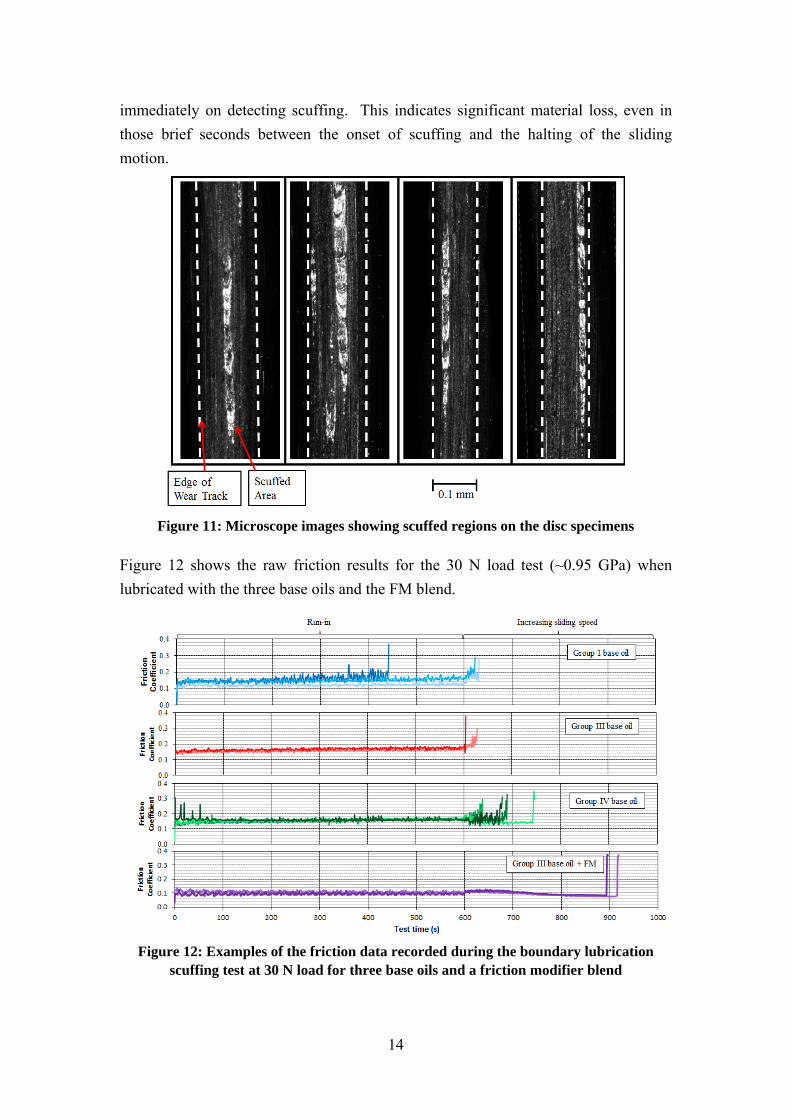
Figure 11 shows some examples of scuffed areas produced on the disc samples in the
boundary lubrication scuffing test.
When the scuffing failure occurs at low speeds it is possible to stop the test quickly,
and then analyse the surfaces to gain an insight into the scuffing mechanism.
Sometimes only one scuffed area is found over the entire area of the disc, but even
this small area (< 1 mm in length) causes the dramatic increase in friction required to
indicate scuffing in our test method. The location of the scuffed areas can be at the
edge or in the middle of the wear track, and usually appears as many arrowheads in a
line pointing towards the direction of sliding. The arrowheads are areas of metal
which is slightly raised from the original surface, presumably formed by transfer of
material from the counter surface, or by the deformation of the surface at the elevated
temperatures during scuffing.
When the failure occurs at high speeds, the damage to the surfaces is extensive and
fast. The entire contact area appears scuffed and the contact width is substantially
wider than the nominal Hertzian contact width, even when the instrument is halted
14
immediately on detecting scuffing. This indicates significant material loss, even in
those brief seconds between the onset of scuffing and the halting of the sliding
motion.
Figure 11: Microscope images showing scuffed regions on the disc specimens
Figure 12 shows the raw friction results for the 30 N load test (~0.95 GPa) when
lubricated with the three base oils and the FM blend.
Figure 12: Examples of the friction data recorded during the boundary lubrication
scuffing test at 30 N load for three base oils and a friction modifier blend
15
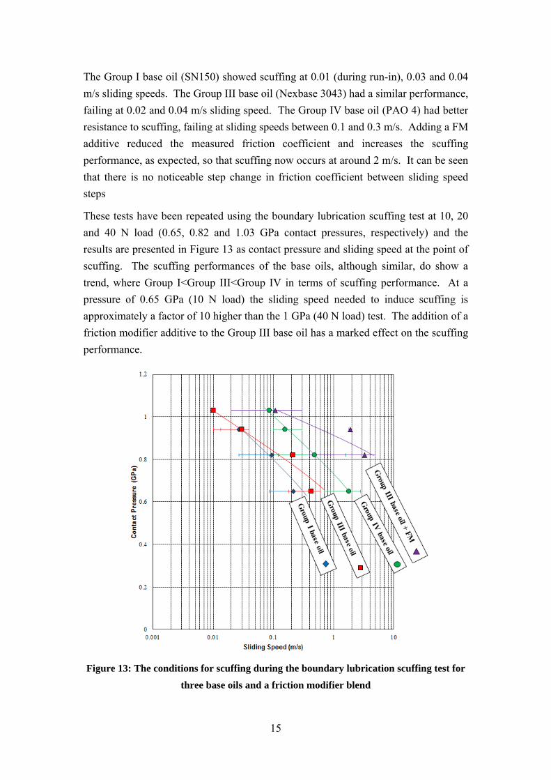
The Group I base oil (SN150) showed scuffing at 0.01 (during run-in), 0.03 and 0.04
m/s sliding speeds. The Group III base oil (Nexbase 3043) had a similar performance,
failing at 0.02 and 0.04 m/s sliding speed. The Group IV base oil (PAO 4) had better
resistance to scuffing, failing at sliding speeds between 0.1 and 0.3 m/s. Adding a FM
additive reduced the measured friction coefficient and increases the scuffing
performance, as expected, so that scuffing now occurs at around 2 m/s. It can be seen
that there is no noticeable step change in friction coefficient between sliding speed
steps
These tests have been repeated using the boundary lubrication scuffing test at 10, 20
and 40 N load (0.65, 0.82 and 1.03 GPa contact pressures, respectively) and the
results are presented in Figure 13 as contact pressure and sliding speed at the point of
scuffing. The scuffing performances of the base oils, although similar, do show a
trend, where Group I<Group III<Group IV in terms of scuffing performance. At a
pressure of 0.65 GPa (10 N load) the sliding speed needed to induce scuffing is
approximately a factor of 10 higher than the 1 GPa (40 N load) test. The addition of a
friction modifier additive to the Group III base oil has a marked effect on the scuffing
performance.
Figure 13: The conditions for scuffing during the boundary lubrication scuffing test for
three base oils and a friction modifier blend
16
The results for the EP additive blend in the boundary lubrication regime test are not
included as this oil showed substantial corrosion and wearing during the test, which
was indicated by a high friction coefficient and substantial material loss and
discoloration. This made determination of the point of scuffing difficult and
inaccurate. The addition of a corrosion inhibitor or other competing surface additives
to the EP formulation should prevent substantial corrosion and allow this method to
be used.
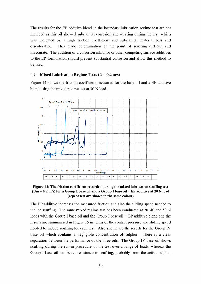
4.2 Mixed Lubrication Regime Tests (U = 0.2 m/s)
Figure 14 shows the friction coefficient measured for the base oil and a EP additive
blend using the mixed regime test at 30 N load.
Figure 14: The friction coefficient recorded during the mixed lubrication scuffing test
(Um = 0.2 m/s) for a Group I base oil and a Group I base oil + EP additive at 30 N load (repeat test are shown in the same colour)
The EP additive increases the measured friction and also the sliding speed needed to
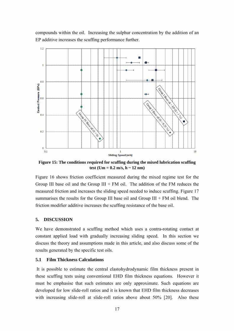
induce scuffing. The same mixed regime test has been conducted at 20, 40 and 50 N
loads with the Group I base oil and the Group I base oil + EP additive blend and the
results are summarised in Figure 15 in terms of the contact pressure and sliding speed
needed to induce scuffing for each test. Also shown are the results for the Group IV
base oil which contains a negligible concentration of sulphur. There is a clear
separation between the performance of the three oils. The Group IV base oil shows
scuffing during the run-in procedure of the test over a range of loads, whereas the
Group I base oil has better resistance to scuffing, probably from the active sulphur
17
compounds within the oil. Increasing the sulphur concentration by the addition of an
EP additive increases the scuffing performance further.
Figure 15: The conditions required for scuffing during the mixed lubrication scuffing
test (Um = 0.2 m/s, h ~ 12 nm)
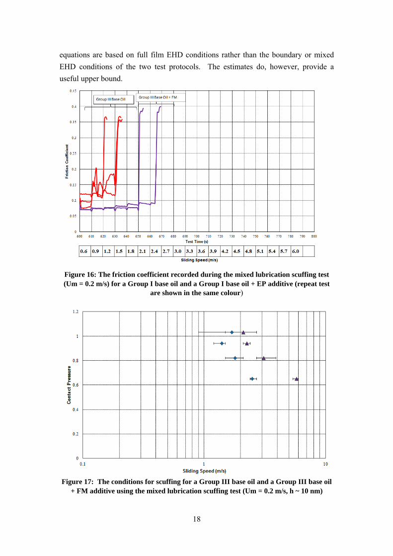
Figure 16 shows friction coefficient measured during the mixed regime test for the
Group III base oil and the Group III + FM oil. The addition of the FM reduces the
measured friction and increases the sliding speed needed to induce scuffing. Figure 17
summarises the results for the Group III base oil and Group III + FM oil blend. The
friction modifier additive increases the scuffing resistance of the base oil.
5. DISCUSSION
We have demonstrated a scuffing method which uses a contra-rotating contact at
constant applied load with gradually increasing sliding speed. In this section we
discuss the theory and assumptions made in this article, and also discuss some of the
results generated by the specific test oils.
5.1 Film Thickness Calculations
It is possible to estimate the central elastohydrodynamic film thickness present in
these scuffing tests using conventional EHD film thickness equations. However it
must be emphasise that such estimates are only approximate. Such equations are
developed for low slide-roll ratios and it is known that EHD film thickness decreases
with increasing slide-roll at slide-roll ratios above about 50% [20]. Also these
18
equations are based on full film EHD conditions rather than the boundary or mixed
EHD conditions of the two test protocols. The estimates do, however, provide a
useful upper bound.
Figure 16: The friction coefficient recorded during the mixed lubrication scuffing test (Um = 0.2 m/s) for a Group I base oil and a Group I base oil + EP additive (repeat test
are shown in the same colour)
Figure 17: The conditions for scuffing for a Group III base oil and a Group III base oil
+ FM additive using the mixed lubrication scuffing test (Um = 0.2 m/s, h ~ 10 nm)
19
For the geometry and materials used in this study, the theoretical, central
elastohydrodynamic film thickness, h reduces to;
67.01540 Uh nm (3)
where U is the entrainment speed in m/s and is the dynamic viscosity in Pas. This
assumes an applied load of 10 N and a representative lubricant pressure-viscosity
coefficient of 17 x 10-9 m2/N. The reduced radius (R’) and reduced Young’s modulus
(E’) are calculated as 4.8 x 10⁻³ m and 2.3 x 10¹¹ Pa respectively. Thus for a lubricant
of viscosity 0.003 Pas at U = 0.003 m/s, h ≈ 1 nm. This is far less than the composite
surface roughness of approximately 15 nm. For an entrainment speed U = 0.2, in the
mixed lubrication scuffing test, the theoretical film thickness increases to h ≈ 11 nm,
which is comparable to the composite surface roughness. These estimates thus
confirm that the low entrainment speed test operates in boundary lubrication while the
higher entrainment speed test is probably mixed boundary-EHD.
One potential complication to the above estimates is that there is some evidence that a
small EHD film can exist between contra-rotating bodies, such as those in a
retainerless ball bearing. A study by Shogrin [21] has measured a small film ascribed
to lubricant entrainment in a contra-rotating contact under zero entrainment velocity
(ZEV) conditions. Guo [22] has modelled a ZEV contact and compared the results to
an experimental study of a similar contact by Yagi [23]. Both show a localised elastic
deformation of the steel surfaces in the centre of the contact point, referred to as a
dimple. This suggests that the classical EHD theory which we have assumed in this
work may need further investigation when applied to very low entrainment speed but
high sliding speed conditions. The high shear rate of the contra-rotating contact is
also expected to complicate the film thickness calculation.
Making accurate measurements of film thickness under contra-rotating conditions is
challenging, as it is difficult to use the conventional optical interferometry EHD
method [24] due to the rapid destruction of the silica coating under the high sliding
conditions. In principle a capacitance or ultrasonic method might be used but these
are not well suited to study lubricant films of thickness 1 to 10 nm.
5.2 Increasing speed vs increasing load
To estimate the conditions at which scuffing is induced in a particular system, the
speed or load can be gradually increased until scuffing occurs. When an increasing
load test is used, a characteristic high friction peak is seen at the start of every load
stage. This is believed to originate from a new area of steel specimen coming into
contact as the increased load results in an increased contact width, with the newly
contacting surface not initially having a protective tribofilm. Scuffing is thus likely to
20
originate at the edge of the contact in the step load tests. This effect is not generally
seen in increasing sliding speed tests which is why these are used predominantly in
this study.
5.3 Base oil behaviour
One noteworthy feature of the scuffing results is that in the boundary scuffing test the
Group I oil scuffed more easily than the Group IV oil, with the Group III oil being
intermediate. However in the mixed lubrication test the order was reversed, with the
Group IV oil scuffing more easily than the Group I and Group III oil. In general one
would expect that base oils with active sulphur constituents, i.e. Group I, to have
greater scuffing performance, due to their ability to smooth the surface and form a
protective boundary films. There are two possible reasons for this reversal:
1. If the “dimple” mechanism is occurring in our contact, the Group IV base oil
(synthetic PAO) may be preventing scuffing in a similar way to that described in
the work by Shogrin [21]. The reason for the superiority of the PAO is unknown,
but may be clarified as the “dimple” mechanism is studied further. It is likely to
be based on the physical properties of the base oils, which in turn will affect their
ability to form a viscous film in the contact and the observed dimple response.
In the mixed lubrication scuffing test, when the entrainment speed is 0.2 m/s, the
“dimple” effect may be lost.
2. Different run-in procedures are used for the two tests. The sliding speeds of the
two test sequences during the run-in are 0.3 and 0.01 m/s for the mixed and
boundary regime test respectively. So during the mixed regime sequence the
sliding distance experienced by the samples is significantly higher during the run-
in period, which may afford the active sulphur compounds within the Group I and
Group III base oils greater opportunity to reduce the roughness of the surfaces
and form a protective FeS2 layer.
5.4 Action of FM and EP additives
Friction modifiers and extreme pressure additives are used here to enhance the
scuffing performance of the base oils. Both are shown to increase the scuffing
performance, but their actions at the metal surfaces differ.
EP additives have two mechanism of preventing scuffing:
1. The sulphur containing molecules can react quickly with any exposed nascent
metal surface, preventing any metallic bonding between metal atoms across
the sliding interface. This is indicated by the transient nature of the high
friction spikes in our test (Figure 14). The friction spikes are presumably due
to the exposure of the reactive nascent metal below the FeO surface, causing a
21
temporary high friction interface. The sulphur compounds in the lubricant
then quickly react with the exposed surface, preventing significant scuffing.
These high friction spikes are not observed for the PAO base oil, which
contains no reactive sulphur compounds.
2. The FeS2 layer is easily sheared from the surface [25] helping to smooth the
metal surface, and reduce asperity interactions between the surfaces. This will
reduce the likelihood of any two asperities meeting and initiating scuffing.
Organic friction modifiers additives, such as the one used in this study, physisorb or
chemisorb to metal surfaces, forming protective boundary films. These films reduce
friction between two sliding bodies, by reducing contact between the surface
asperities and replacing it with a low shearing interface [26, 27]. The FM film
prevents scuffing by preventing asperity contact and maintaining a low friction
contact, and thus low heat generation. During shearing of the FM film, part of the
film can be removed, but as the layers are in contact with a lubricant the boundary
layers can be replenished by the free surfactant in the lubricant. The FM film
adsorption and desorption is thermally governed, thus above a critical flash
temperature the polar molecules may become sufficiently depleted or disoriented,
resulting in an unprotected metal surface and scuffing [10].
5.5 Test variability
One clear feature that emerges from this study is the large variability in results, even
using closely-controlled test conditions and specimens and with a run-in period. This
variability is not generally found in friction or wear measurements and is more
reminiscent of the statistical nature of fatigue tests. It almost certainly reflects the
criticality of scuffing, which is not based on any average response but is triggered by
some critical condition, from which scuffing then proceeds catastrophically. This
may be a slight variation in surface roughness, at a level which is not important in
friction or wear tests, or even the chance presence of hard inclusions within the
contact track for some specimens but not others.
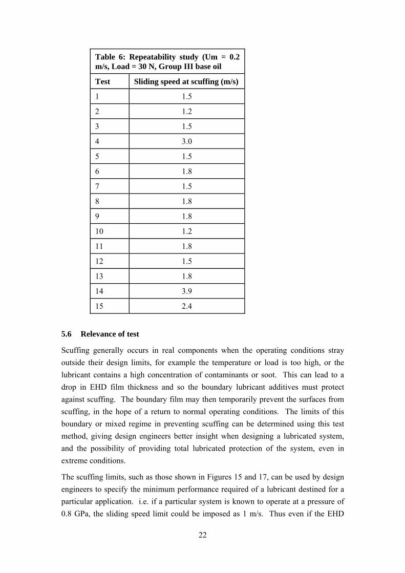
The variability of this contra-rotating scuffing test was explored by carrying out
fifteen repeated tests on the Group III base oil at Um = 0.2 m/s and 30 N load. The
sliding speed at which the tests failed are shown in Table 6 and have been fitted to the
general Weibull distribution [28], as is conventional done when analysing rolling
contact fatigue data. The results show a Weibull slope of = 3.1, which is closer to
the normal distribution region of the Weibull form than the type of skewed
distribution found in fatigue experiments, where is more typically 2.
22
Table 6: Repeatability study (Um = 0.2 m/s, Load = 30 N, Group III base oil
Test Sliding speed at scuffing (m/s)
1 1.5
2 1.2
3 1.5
4 3.0
5 1.5
6 1.8
7 1.5
8 1.8
9 1.8
10 1.2
11 1.8
12 1.5
13 1.8
14 3.9
15 2.4
5.6 Relevance of test
Scuffing generally occurs in real components when the operating conditions stray
outside their design limits, for example the temperature or load is too high, or the
lubricant contains a high concentration of contaminants or soot. This can lead to a
drop in EHD film thickness and so the boundary lubricant additives must protect
against scuffing. The boundary film may then temporarily prevent the surfaces from
scuffing, in the hope of a return to normal operating conditions. The limits of this
boundary or mixed regime in preventing scuffing can be determined using this test
method, giving design engineers better insight when designing a lubricated system,
and the possibility of providing total lubricated protection of the system, even in
extreme conditions.
The scuffing limits, such as those shown in Figures 15 and 17, can be used by design
engineers to specify the minimum performance required of a lubricant destined for a
particular application. i.e. if a particular system is known to operate at a pressure of
0.8 GPa, the sliding speed limit could be imposed as 1 m/s. Thus even if the EHD
23
film of the system is lost, the boundary lubrication film may prevent scuffing, at least
temporarily.
6. SUMMARY
A new scuffing test is described in this article that uses contra-rotating surfaces to
limit EHD films even at high sliding speeds (up to 6 m/s). We have demonstrated this
novel technique and show how the method can be used to differentiate the scuffing
resistance of different lubricated systems. Specifically we used test samples
manufactured from AISI 52100 steel and simple base oil blends (Group I, III & IV
base oils with EP and FM additives). The results show that:
Scuffing is dependent on the entrainment speed and thus the film thickness –
higher sliding speeds are needed to induce scuffing in a system which is
operating in the mixed regime as opposed to the boundary regime.
The sulphur compounds found naturally within Group I base oils can inhibit
scuffing.
EP and FM additives can improve the scuffing performance of the base oils
The variation of our results are normally distributed and may be due to minor
differences on the morphology, composition or microstructure of the surfaces
of the metal samples
The scuffing tendency can be portrayed as scuffing design maps (contact pressure
against sliding speed), similar to previous transition diagrams [6]. The critical zones
of scuffing can then be easily identified and separated from the safe operating
condition for a particular system.
The contra-rotation method offers two major advantages over current methods:
it achieves very high sliding speeds while maintaining low entrainment speeds
it studies the scuffing resistance of lubricants independent of the latters’
viscosity
This will be useful to the tribology community as this method has the potential to
allow the development of better lubricants, steels and coatings which have a better
scuffing resistance. This in turn will allow the development of smaller and lighter
machine components which can operate with greater efficiency.
7. ACKNOWLEDGMENTS
The authors wish to thank two research students, Christopher Salt and Joshua
Maguire, who worked on the early development of this contra-rotating technique at
24
Imperial College. We also express our gratitude to Amir Kadiric, Mark Fowell and
Matt Smeeth for their input to this work.
8. REFERENCES
[1] F.F. Musgrave, The development and lubrication of the automotive hypoid gear,
J. Inst. Pet. 32 (1946) 32-44
[2] G. Neely, Extreme-Pressure Lubricants Testing, SAE Technical Paper 360125,
(1936) doi:10.4271/360125
[3] ASTM Standard test method for measurement of extreme-pressure properties of
lubricating fluids (four-ball method), ASTM D2783 - 03(2009).
[4] ASTM Standard test method for measurement of extreme-pressure properties of
lubricating fluids (Timken Method), ASTM D2782 - 02(2014).
[5] O.Bridgeman, The present status of the extreme pressure lubrication problem.
SAE Technical Paper 340011, (1934) doi:10.4271/340011 [6] A.W.J de Gee, A. Begelinger, G. Salomon, Failure mechanisms in sliding
lubricated concentrated contacts, Proc. 11th Leeds-Lyon Symp. on Tribol, Mixed
Lubrication and Lubricated Wear, Leeds, 1984, 105-124.
[7] D.J. Schipper, A.W.J. de Gee, Lubrication modes and the IRG Transition
Diagram, Lubr. Sci. 8, (1995) 27-35. DOI: 10.1002/ls.3010080104
[8] W.F. Bowman, G.W. Stachowiak, A review of scuffing models, Tribol. Lett. 2,
(1996) 113-131. DOI: 10.1007/BF00160970
[9] H. Blok, Theoretical study of temperature rise at surfaces of actual contact
under oiliness lubricating conditions, Proc. Gen. Discuss. Lubr. Inst. Mech.
Eng. London, (1937) 222-235.
[10] H. Spikes, A. Cameron, Scuffing as a desorption process – an explanation of the
Borsoff effect, ASLE Trans. 17, (1974) 92-96. DOI: 10.1080/
05698197408981442
[11] A. Dyson, The Failure of Elastohydrodynamic Lubrication of Circumferentially
Ground Discs, Proc. Inst. Mech. Eng. 190. (1976) 677-711. DOI: 10.1243/
PIME_PROC_1976_190_074_02
[12] H.S. Cheng, A. Dyson, Elastohydrodynamic Lubrication of Circumferentially-
Ground Rough Disks, ASLE Trans. 21, (1978) 25-29 DOI: 10.1080/
05698197808982858
25
[13] J. Enthoven, H.A. Spikes, Infrared and visual study of the mechanisms of
scuffing, Tribol. Trans. 39 (1996) 441-447. DOI:10.1080/ 10402009608983550
[14] J. Hershberger, O.O. Ajayi, J. Zhang, H. Yoon, G.R. Fenske, Evidence of
scuffing initiation by adiabatic shear instability, Wear 258, (2005) 1471 – 1478.
DOI: 10.1016/j.wear.2004.10.010
[15] D. Dowson, B.J. Hamrock, Ball Bearing Lubrication. The Elastohydrodynamics
of Elliptical Contacts. John Wiley & Sons 1981.
[16] H. Blok, Gear wear as related to viscosity of gear oils, Proc. Summer
Conference - MIT, Mech. Wear, June 1948, publ. ASME (1948) 199-227.
[17] L.V. Wedeven, Load capacity method, Wedeven Associates Inc. website
www.wedeven.com.
[18] J. Fan, H.A. Spikes, New test for mild lubricated wear in rolling-sliding
contacts, Tribol. Trans. 50, (2007) 145-153. DOI: 10.1080/10402000701255476
[19] J. Maguire, Development of a new scuffing test, Imperial College 4M Project
Report, (2007)
[20] M. Smeeth, H.A. Spikes, The influence of slide/roll ratio on the film thickness
of EHD contact operating within the mixed lubrication regime, Proc. 22nd
Leeds-Lyon Symp. Tribol, (1995).
[21] B.A. Shogrin, W.R. Jones Jr, E.P. Kingsbury, M.J. Jansen, J.M. Prahl,
Experimental study of load carrying capacity of point contacts at zero
entrainment velocity, NASA/TM-1998-208650 (1998)
[22] F. Guo, P.L. Wong, P. Yang, K. Yagi, Film formation in EHL point contacts
under zero entraining velocity conditions, Tribol. Trans., 45 (2002), 521-530.
DOI: 10.1080/10402000208982583
[23] K. Yagi, K. Kyogoku, T. Nakahara, Temperature measurement of oil film and
surface in point contact EHL under high slip ratio condition, Proc. Int. Tribol.
Conf. (2000) Nagasaki, 375-385.
[24] H.A. Spikes, Sixty years of EHL, Lubr. Sci. 18, (2006) 265-291. DOI:
10.1002/ls.23
[25] M.N. Najman, M. Kasrai, G.M. Bancroft, X-ray absorption spectroscopy and
atomic force microscopy of films generated from organosulfur extreme-pressure
(EP) oil additives, Tribol. Lett. 14, (2003) 225-235. DOI: 10.1023/
A:1022650516272

26
[26] F. Bowden, D. Tabor, The friction and lubrication of solids, Clarendon Press,
Oxford, 1986.
[27] I. Iliuc, Tribology of thin layers, Elsevier, Romania, 1974.
[28] W. Weibull, A statistical distribution function of wide application, ASME pap.
51-A-6 (1951).