Embed Size (px)
Citation preview

Research ArticleA New Model for Predicting Flow in Fractured-Vuggy CarbonateReservoirs under Pseudosteady State Condition
Nai Cao ,1,2,3 Gang Lei ,4 Yuan Su,1,2 Hong Li ,3 Jiali Zhang,1,2 and Ci Zhang1,2
1State Key Laboratory of Shale Oil and Gas Enrichment Mechanisms and Effective Development, Beijing, 102206, China2Sinopec Research Institute of Petroleum Engineering, Beijing 102206, China3State Key Laboratory of Petroleum Resources and Prospecting, China University of Petroleum, Beijing 102249, China4Faculty of Engineering, China University of Geosciences, Wuhan 430074, China
Correspondence should be addressed to Gang Lei; [email protected]
Received 16 July 2021; Revised 16 September 2021; Accepted 25 September 2021; Published 22 October 2021
Academic Editor: Wei Yu
Copyright © 2021 Nai Cao et al. This is an open access article distributed under the Creative Commons Attribution License, whichpermits unrestricted use, distribution, and reproduction in any medium, provided the original work is properly cited.
For constant rate production of a single well in a closed boundary fractured-vuggy carbonate reservoir, when the pressure wavepropagates to the reservoir boundaries, boundary-dominated flow occurs, and the transient flow period ends, the reservoir willbe in a state of pseudoequilibrium (i.e., pseudosteady state flow occurs, and the pressure at any point in the reservoir declinesat the same constant rate over time). The characterization of fluid flow in the fractured-vuggy carbonate reservoir underpseudosteady state condition is of significance in describing the productivity index (PI) of the well. However, due to complexmechanisms (e.g., stress dependency of reservoir properties and crossflow between different systems of the reservoirs) duringflow in fractured-vuggy carbonate reservoirs, researches on productivity prediction in fractured-vuggy carbonate reservoirsunder pseudosteady state are very limited. The present work is aimed at developing a new analytical model for predicting flowin fractured-vuggy carbonate reservoirs under pseudosteady state condition. In the derived model, the crossflow betweendifferent systems (i.e., matrix, fracture, and vug) of the reservoirs was taken into account. In addition, based on Hooke’s law, aquantitative model was proposed to study stress-dependent permeability of the fracture system, which connects the reservespaces. Moreover, the roughness morphology characteristics of fracture surface were taken into account with fractal theory.Finally, with our derived model, influences caused by various related factors on productivity were analyzed. The results showthat well productivity during pseudosteady flow will be significantly affected by the morphology of fracture surface (e.g.,fracture microstructure parameters) and effective stress. Specifically, due to effective stress, the fracture system in the fractured-vuggy reservoirs will be deformed, and the corresponding properties (e.g., permeability, porosity, and conductivity) will change,leading to the change of well productivity. In addition, there exists a negative relationship between the elastic storage capacityratio of vugs and well productivity during pseudosteady flow. Moreover, a larger value of matrix-fracture interporosity flowcoefficient or vug-fracture interporosity flow coefficient corresponds to a larger value of well productivity during thepseudosteady period. The new derived model is beneficial to improve the productivity prediction accuracy and reduceuncertainty. What is more, the findings of this study can help for providing theoretical reference for the design of efficientdevelopment of fractured-vuggy carbonate reservoirs.
1. Introduction
Huge reserves are explored in carbonate rocks worldwide,and the known economic reserves of it increase year by year[1, 2]. For example, more than half of the world’s largestcrude oil and natural gas reserves are found in carbonate
rocks. In addition, carbonate rocks produce a significantportion of the world’s oil and gas. Thus, how to efficientlyexploit these resources attracts attention all over of theworld [1–4]. Taking China for example, according to thestatistics of the Ministry of Natural Resources of China,in 2018, 7176 × 104 t of proved oil and gas reserves of
HindawiGeofluidsVolume 2021, Article ID 5613966, 13 pageshttps://doi.org/10.1155/2021/5613966

Ordovician carbonate rocks (fractured-vuggy carbonatereservoirs) in Shunbei was reported [2]. As stated in theliterature [3–8], in the near future, the resources of car-bonate reservoirs will be one of the main battlefields for“increasing reserves and productivity” in China.
In general, influenced by a variety of geological pro-cesses, the carbonate reservoirs are heterogeneous, and thereservoir spaces are typically dual or triple porosity systems,which are different in size and complex in distribution. Forfractured-vuggy carbonate reservoirs, the reservoirs can beclassified as matrix system, fracture system, and vug system,in which the vug system is the main reservoir space, andfractures with larger permeability work as the main flowchannels [5–7]. Physically speaking, during the developingprocess, formation permeability of each system in the reser-voirs will decrease with the increasing effective stress [8]. Forexample, affected by effective stress, matrix compression (orvug deformation) will result in permeability decease ofmatrix system (or vug systems), and fracture closure willlead to permeability decrease of fracture system. Yan et al.[9] conducted stress sensitivity experiments on 12 core sam-ples (e.g., natural fractured samples, artificial fractured sam-ples, single cavity samples, and double cavity samples) fromTahe oilfield and found that the stress sensitive of vug sys-tem was weak. In addition, they suggested that the vug sys-tem would weak the stress sensitive degree of fractured-vuggy reservoirs [9]. That is, compared with permeabilitydecrease due to matrix compression or deformation of vugsystems, fracture closure plays a more crucial role in causingthe decrease in formation permeability [8–12]. Thus, thematrix system stress sensitivity (or vug system stress sensi-tivity) is much less evident in the fractured-vuggy formation.Moreover, when the fractures are highly penetrated, forma-tion stress sensitivity will be dominated by fracture systemstress sensitivity [8–13]. In this paper, to simplify the model,the fracture system is assumed to be highly penetrated; thus,the formation stress sensitivity is mostly determined by thestress sensitivity of the fracture system [8–13]. It is wellknown that, with the decrease of formation permeabilitydue to effective stress, well productivity will decrease, andthe effective development becomes more difficult [8–13].Therefore, it is of theoretical and scientific significance toquantify the stress sensitivity of fracture system permeabilityand its impact on productivity of fractured-vuggy carbonatereservoirs [14–18].
In essence, the surface of the fracture system is roughand has complex morphological characteristics, making theeffective stress on the fracture surface unevenly distributed,leading to the extremely complex stress sensitivity of thefracture system [19–23]. However, to the best of our knowl-edge, many former studies seldom coupled the microstruc-ture characteristics of the fracture surface with effectivestress, and these models contained empirical parameters,whose physical meaning was unclear [18–21]. In 1978,Gangi proposed a theoretical model to quantify the stressdependent permeability of fractures [19]. In this derivedmodel, the roughness of fractures was represented by smallcylinders unevenly distributed on smooth fracture surfaces.After that, a number of scholars continued to deepen the
understanding of stress sensitivity of fractured media[10–13, 15, 20–22]. For example, by combining theCarman-Kozeny model and a derived stress dependentporosity model, Mckee et al. studied the stress dependentpermeability of fractures considering the fracture geometry[15]. Based on fractal theory and Gangi’s model, Lei et al.proposed theoretical models to study stress dependent per-meability and relative permeability of rough fractures [11,13]. Moreover, some scholars used small cylinders with dif-ferent elastic modulus to characterize fracture fillers andstudied the closure law of filled fractures under effectivestress with the Hertz elastic contact model [20, 21]. Recently,Cao et al. took the fractures as distinct objects and derived atheoretical model to study stress dependent permeability offractures [22]. In this derived model, they also studied theinfluence of the extent of fracture penetration on stress-dependent permeability of fractures. Based on the discus-sions above, it is clear that, though many related work hasbeen done, the relative theoretical research is yet to be fur-ther improved for accurate description of fracture systemstress sensitivity. Thus, to precisely analyze the stress sensi-tivity of the rough fracture system, the influence of fracturemicrostructure on stress sensitivity of the fracture system,which further influence the well productivity, remains tobe clarified and analyzed.
It is well known that, to better understand the flow inporous media, it is of great significance to conduct pro-ductivity predictions. To the best of our knowledge, forproductivity prediction of fractured-vuggy reservoirs,applicable mathematical models have been developed fromoriginal homogeneous model to double and triple mediummodels. However, until now, related literature devoted todevelop inflow performance relationship curve (IPR curve,i.e., production versus drawdown pressure) of vertical wellin fractured-vuggy reservoirs is scarce. In addition, thoughstress sensitivity has been coupled with dual mediummodel, the influence of fracture stress sensitivity on wellproductivity of fractured-vuggy reservoirs has rarely beenreported. However, physically speaking, the stress sensitiv-ity of fracture systems directly restricts the communicationability of fractured-vuggy reservoirs under overburdenpressure and the fluid supply efficiency of reservoirs towellbore [24, 25]. Therefore, the influence mechanism ofstress sensitivity of rough fracture on productivity offractured-vuggy carbonate reservoirs is await to be furtherclarified.
For a constant production well in a closed fractured-vuggy reservoir, fluid flow will occur in early-time, middle-time, and late-time regions, respectively [26]. In general, inthe early-time region, fluid flow will be affected by wellbore.When the fluid flow progresses to the middle-time region,the flow will be driven by outward diffusion of the pressuredrawdown (i.e., the propagation of pressure wave). As pro-duction progresses, when the pressure wave propagates tothe closed boundary, fluid flow occurs in the late-time region(i.e., pseudo-steady state flow region). Physically speaking,during pseudosteady state flow region, fluid flow is drivenby the volumetric compression of the reservoir, and the rateof change of pressure will be constant over time [27–29]. In
2 Geofluids

particular, for fluid flow in multiple media under pseudos-teady state flow region, the fluid transfer between differentsystems (e.g., fracture-matrix system and fracture-vug sys-tem) ais proportional to the pressure changes [30]. Todescribe the well productivity index (PI), many scholars con-ducted theoretical works to characterize fluid flow underpseudosteady state condition [31–36]. For example, Leiet al. proposed analytical models to study productivity ofwells in tight sandstone reservoirs under pseudosteady state[31, 32]. In the derived models, the stress sensitivity of tightmatrix was taken into account. However, in these models,the crossflow between fracture system and matrix systemwas ignored. With material balance constraint, Morgan pro-posed a production forecasting model for tight gas well [33].However, the model never took effective stress into account.Moreover, the crossflow between different systems wasignored. Based on the assumption of linear flow from reser-voir to fracture and linear flow in the fracture, Zhang et al.established an analytical productivity model of multifrac-tured shale gas wells [34]. They concluded that the predic-tion from their model was in good agreement with actualdata of gas wells in North American and China. However,their model did not take effective stress into account. Al-Rbeawi studied multiphase flow with different wellbore con-ditions under pseudosteady state [35]. For triple media,Youssef and Alnumaim proposed an analytical model tostudy well productivity during pseudosteady state flowregion. In their model, the crossflow between different sys-tems was taken into account. However, the derived modelalso failed to take effective stress into account. Thus, devel-oping a theoretical well productivity model for the pseudos-teady state flow is needed to deepen the understanding offluid flow in fractured-vuggy reservoirs.
To sum up, the objectives of this work are (1) todevelop an analytical model for predicting well productiv-ity of fractured-vuggy carbonate reservoirs under pseudos-teady state, (2) to study the stress dependent permeabilityof rough fractures and its impact on well productivity, and(3) to explore the influence of various factors on well pro-ductivity of fractured-vuggy carbonate reservoirs, therebyproviding supports for developing designs. Motivated bythis, in this work, a productivity prediction model for ver-tical wells in fractured-vuggy carbonate reservoirs underpseudosteady state is established, in which morphologysurfaces of rough fractures are taken into account. In thederived model, the stress sensitivity of the fracture systemis quantitatively presented. Moreover, the triple media(matrix, fracture and vug) model is applied to characterizeflow in the fractured-vuggy carbonate reservoirs. With theproposed model, the influence brought by the stress sensi-tivity of rough fracture system on the well productivity isdiscussed. Based on the general sketch of this work(Figure 1), the outline of this work can be summarizedas follows: firstly, the mathematical model and the work-flow of solution determination will be described in Section2. Then, model results and the influence of related param-eters on well productivity will be discussed in Section 3.Finally, the conclusions will be summarized and presentedin Section 4.
2. Mathematical Model
2.1. Model Assumptions. In this work, the fractured-vuggycarbonate reservoir is simplified as the triple mediumshown in Figure 2(a). It is assumed that the reservoir isisotropic, and it is consist of evenly distributed matrix,fracture systems, and vug systems. The single-phase fluidin the reservoir is microcompressible, and the flow ofwhich obeys the Darcy’s law. The flow is isothermal dur-ing the whole process, and it has reached a pseudosteadystate. The fluid supply to the wellbore is stable, and onlyradial flow in horizontal direction is considered.Figure 2(b) depicts the whole flow process: the fluid flowsinto the wellbore only through the fracture systems, andthere exists crossflow between matrix fracture and vugfracture. That is, both matrix and vug systems will supplyfluid to fracture systems.
2.2. Flow Equations and the Solutions. Based on the assump-tions stated above, the equations for describing fluid flow infractured-vuggy reservoir are as follows [36–38]:
Fracture system:
K f
μ
∂2pf∂r2
+ 1r
∂pf∂r
!= αm
Km
μpf − pm� �
+ αvKv
μpf − pv� �
+ φf Cf
∂pf∂t
:
ð1Þ
Matrix system:
φmCm∂pm∂t
= αmKm
μpf − pm� �
: ð2Þ
Triple media seepage equations
Productivity prediction model
Influence analysis of stress sensitivity
Discussion of influencing parameters
Results discussion
Stress sensitivity of fracture system with
rough surface
Figure 1: General sketch of this work.
3Geofluids

Vug system:
φvCv∂pv∂t
= αvKv
μpf − pv� �
, ð3Þ
where μ is the fluid viscosity, mPa·s; p is the formation pres-sure, MPa; K is the permeability, μm2; α is the shape factor,m-2; t is the production time, d; C is the compressibility coef-ficient, MPa-1; φ is porosity, %; subscripts f , v, and m,respectively, stand for fractures, vugs, and matrix; r is thedistance, m.
As aforementioned, during pseudosteady state flowregion, the pressure drop are stable and consistent through-out the reservoir, and the volumetric compression of the res-ervoir is the dominated driving force for fluid flow [31–36].Thus, for fluid flow in fractured-vuggy reservoirs, we have[30, 36]
∂pf∂t
= ∂pm∂t
= ∂pv∂t
= −qscB
VB φf Cf + φmCm + φvCv
� � , ð4Þ
where B is the fluid bulk coefficient, m3/m3; VB is the fluidvolume under formation condition, m3; qsc is the productiv-ity at ground standard condition, m3/d.
Substituting Eq. (4) into Eq. (1), we have
K f
μ
∂2pf∂r2
+ 1r
∂pf∂r
!= qscB
VB: ð5Þ
The boundary conditions can be described as
pf���r=rw
= pwf , ð6Þ
r∂pf∂r
����r=re
= 0, ð7Þ
where pwf is the bottom hole pressure, MPa; re is the radiusof the reservoir, m; rw is the wellbore radius, m.
By solving Eqs. (5)–(7), the pressure at the fracture sys-tem is [36]
pf r, tð Þ = pwf tð Þ + qscμB2K f VB
r2e lnrrw
� �− 0:5 r2 − r2w
� � ,
VB = πH r2e − r2w� �
,
8><>:
ð8Þ
where H is the reservoir effective sickness, m.Mathematically speaking, for triple media with multiple
systems, the average reservoir pressure can be regarded asthe mean of average pressure in each system. Therefore, itis crucial to determine the weighting coefficient of each sys-tem. In general, the weighting coefficient is related to porevolume of each system. However, as the fluid flow duringpseudosteady state is driven by the volumetric compressionof the reservoir, the compressibility coefficient of each sys-tem will also greatly affect the weighting coefficient. Sincethe compressibility coefficient varies with different systems,only pore volume parameter is not enough to be weightingparameters for accurately determining the average reservoirpressure. As stated in the literature, elastic storage capacityratio of each system is more reasonable to be the weightingparameters [36, 39, 40]. That is, the average reservoir pres-sure can be obtained as
�p = �pfωf + �pmωm + �pvωv , ð9Þ
where �pf is the average pressure in the fracture system, �pm is theaverage pressure in the matrix system, �pv is the average pressurein vug system, and the weighting parameter ω is assigned as theelastic storage capacity ratio, which can be defined as
ωi =φiCi
φf Cf + φvCv + φmCmi = f , v,m: ð10Þ
With the assumption that parameter re is much larger thanrw, based on Eq. (8), the average pressure in fracture system canbe written as
Well
Triple medium reservoir
(a) Simplified triple media model
Well Fracture Vug
Matrix
(b) The connection sketch of triple media
Figure 2: Sketch of the physical model.
4 Geofluids

�pf =∰
VBpf dVB
πH r2e − r2wð Þ = pwf tð Þ + qscμB2πKfH
ln rerw
� �−34
: ð11Þ
Then, based on Eqs. (1) and (3), the average pressure in thematrix system and vug system can be, respectively, obtained as
�pm = �pf +qscωmμBr
2w
λmVBK f, ð12Þ
�pv = �pf +qscωvμBr
2w
λvVBK f, ð13Þ
where λm is the matrix-fracture interporosity flow coefficient;λv is the vug-fracture interporosity flow coefficient.
According to the definition of well production index(PI), from Eqs. (9) to (13), we have [36]
J = qsc�p − pwf
=2πK fH
μB ln re/rwð Þ − 3/4½ � ⋅D, ð14Þ
where
D = 11 + 2 rw/reð Þ2 ⋅ ω2
m/λmð Þ + ω2v/λvð Þ½ �/ ln re/rwð Þ − 3/4½ � :
ð15Þ
Eq. (14) demonstrates that, compared with the normalwell production index (PI) model for homogeneous singlecontinuum media, the derived well production index (PI)can be treated as two parts. The first part is Darcy’s PI part,which is identical to the normal well production index (PI)model. Physically speaking, this part takes into accounthow the flow rate is related to pressure drop for the fluidflow in the continuum media. The second part, parameterD, represents how easy the fluid can move from one systemto the others, which is dependent on the crossflowparameters.
2.3. Stress Sensitivity of the Fracture System. Eq. (14) demon-strates that the permeability of the fracture system plays animportant role in the productivity prediction of thefractured-vuggy reservoir in the pseudosteady state stage.However, as stated previously, effective stress will greatlyaffect the permeability of the fracture system. Thus, it is sig-nificant to quantify stress-dependent permeability of thefracture system and couple it with Eq. (14) to study well pro-ductivity more accurately. Due to complex morphology ofthe fracture system, it is difficult to characterize fracturemicrostructure and establish the quantitative relationbetween effective stress and fracture permeability. Fortu-nately, through a series research work, many researchershave found that the fractal geometry theory was applicablein describing the microstructure of the fracture system [11,13, 41–45]. Specifically, fractal theory has been proved tobe applicable and reliable in describing the complex fracturesystem. For example, many scholars suggested that roughsurfaces of fractures had fractal characteristics [41–45]. In
this work, for the sake of simplification, fractal theory willbe applied to characterize fracture morphology, and then,an analytical model of stress-dependent permeability of thefracture system based on fractal theory and Gangi’s modelwill be introduced [11, 19, 44].
Based on Gangi’s model, roughness of fracture surfacecan be regarded as “nails” embedded on the smooth fracturewalls [11, 19]. Then, for fracture walls distributed with“nails” with various lengths, we assume that the length of“nails” follows fractal theory. The fractal dimension of thefracture system roughness can be expressed as [11]
DR = 2 − ln φn
ln lmin/lmaxð Þ , ð16Þ
where DR is the fractal dimension for fracture surface rough-ness (0 <DR < 2), dimensionless. Area ratio of fracture sur-face φn is the ratio of total roughness area to total surfacearea of rough fracture, dimensionless; lmin and lmax, respec-tively, stand for the minimum and maximum length of theroughness, μm. It should be noted that Eq. (16) means thatlmin/lmax < 0:01.
Based on Hooke’s law, the deformation of the “nails” dueto the effective stress can be derived. With the detailed der-ivations stated in Appendix A for a given displacement xof the “nails,” the effective stress exerting on the fracture sur-faces can be expressed as follows [11]:
p = FA
= EπDR ω0 − βminð ÞDR
Aε2⋅
x − ω0ð Þω1−DR0 − ω0 − xð Þ1−DR
1 −DR
+ω2−DR0 − ω0 − xð Þ2−DR
2 −DR
266664
377775
= Eφn 2 −DRð Þl2−DRmax − l2−DR
min
� � ⋅
x − ω0ð Þω1−DR0 − ω0 − xð Þ1−DR
1 −DR
+ω2−DR0 − ω0 − xð Þ2−DR
2 −DR
266664
377775,
ð17Þ
where p is the effective stress, MPa; A is the area of fracture sur-face, μm2; E is the rock elastic modulus, GPa; ω0 is the initialfracture aperture, μm; βmin is the minimum shortness of theroughness, μm; F is the force exerting on the fracture, MPa; εis a constant ratio of the length to the radius of the elements.
Based on cubic law, initial permeability K f 0 and stress-dependent permeability K f can be obtained, respectively
Kf =112 ω0 − xRð Þ2, ð18Þ
Kf 0 =ω0
2
12 : ð19Þ
2.4. The Process of Model Determination. Considering theinfluence brought by the fracture system, the procedure ofproductivity prediction process of fractured-vuggy reservoircan be summarized as follows:
5Geofluids

(1) Based on the initial permeability Kf 0, the initial frac-ture aperture can be determined by Eq. (19)
(2) With the selected microstructure parameters of frac-ture, including φn, lmax, and lmin, the fractal dimen-sion DR can be determined by Eq. (16)
(3) By assigning values to E and xR, the effective stress isdetermined by Eq. (17), and the permeability ofrough fracture system affected by effective stresscan be obtained with Eqs. (17) and (18)
(4) By comparing the experimental data or numericalsimulation data, steps 2 and 3 are repeated to finallydetermine the fracture surface microstructureparameters, rock lithology parameters, and fracturesystem permeability under effective stress
(5) With the determined fracture system permeabilityunder effective stress, the productivity of reservoirin pseudosteady state can be predicted with Eq. (14)
3. Results and Discussions
3.1. Model Validation. In order to show it is reasonable to usethe proposed fractal model to quantitatively present the stresssensitivity of the fracture system, and to show how to obtainfracture parameters using the model, core slices of 2 cores sam-pled from two production wells in Jianghan Basin, China, wereused for verification and illustration [11]. Experiments wereconducted under formation condition using the proppants witha diameter range of 30-60 mesh. It can be seen from Figure 3.that the experimental data of both the two cores showed afriendly match with the calculated data using the fractal model,which means the quantitative model for stress sensitivity of thefracture system is reasonable. Besides, with the stress-dependentpermeability model and the experimental data, we successfullyobtained the fracture parameters of these two core samples.For example, for core sample 1, the initial fracture aperturewas 5:2 × 10⁻³ cm; the minimum and maximum length of theroughness lmin and lmax were 2:5 × 10⁻⁵ cm and 5:2 × 10⁻³ cm, respectively; the area ratio φn was 0.5%; the fractal dimensionfor fracture surface roughnessDR was 1.01; and the elastic mod-ulus E was 45GPa. However, for core sample 2, the initial frac-ture aperture was 5:2 × 10⁻³ cm; the minimum and maximumlength of the roughness lmin and lmax were 2:2 × 10⁻⁵ cm and5:2 × 10⁻³ cm, respectively; the area ratio φn was 1.2%; the frac-tal dimension for fracture surface roughness DR was 1.18; andthe elastic modulus E was 45GPa. It should be noted that thevalue of elastic modulus in the model is identical to that deter-mined from the test results, which validates the rationality of theparameters used in the model.
Lu and Ghedan [46] stated that, for a fully penetratingvertical well located at the center of a close homogeneous,isotropic circular reservoir, the production during pseudos-teady state could be written as
qsc =2π�KH �p − pwf
� �μB ln re/rwð Þ − 3/4½ � , ð20Þ
where parameter �K is the average permeability of the reser-voir. To further validate the proposed model Eq. (13), weassume that the reservoir is just composed of fracture sys-tem. In other words, the matrix system and vug system canbe neglected in the reservoir (i.e., ωv = ωm = 0); then, themodel Eq. (14) can be simplified as
qsc =2πK fH �p − pwf
� �μB ln re/rwð Þ − 3/4½ � : ð21Þ
As the reservoir only contains the fracture system, theaverage permeability of the reservoir is the permeability ofthe fracture system. That is, the average permeability of thereservoir is Kf . Thus, Eq. (21) is identical to Eq. (20), whichvalidates the rationality of Eq. (14).
Recently, Youssef [47] derived an analytical model tostudy IPR curve of fractured-vuggy carbonate reservoirs,which was
J = qsc�p − pwf
=2π Kf + Km
� �HE23
μB ln re/rwð Þ − 3/4½ � ;
1E23
=
1 + 2 rw/reð Þ2ln re/rwð Þ − 3/4½ � :
ω2v
λv + λvm+ ϑ2
γ
1 + rwre
� �2ffiffiffiffiffiffiffiffiffiffiffiffiffiffiffiffiκ 1 − κð Þ
γ
s
⋅K1 βreð ÞI1 βrwð Þ − K1 βrwð ÞI1 βreð ÞK1 βreð ÞI0 βrwð Þ + K0 βrwð ÞI1 βreð Þ
266664
377775
8>>>><>>>>:
9>>>>=>>>>;
* +,
ϑ = ωm + ωvλvm
λv + λvm+ κ − 1 ; κ =
Kf
K f + Km,
γ = λm + λv ⋅ λvmλv + λvm
; β = 1rw
ffiffiffiffiffiffiffiffiffiffiffiffiffiffiffiffiγ
κ 1 − κð Þr
:
8>>>>>>>>>>>>>>>>>>>>>>>>>>><>>>>>>>>>>>>>>>>>>>>>>>>>>>:
ð22Þ
0 10 20 30 40 50 600.2
0.4
0.6
0.8
1.0
K/K
0
P (MPa)eff
Experimental data of core 1 Calculated data of core 1Experimental data of core 2Calculated data of core 2
Figure 3: Comparison of stress-dependent permeability offractures from experimental data and results from the derivedmodel.
6 Geofluids

It should be noted that the derived model Eq. (22) isbased on the assumption that both the fracture system andmatrix system are flow paths for fluid flow in the carbonatereservoirs, and the vug system has direct connections withother two systems. If we assume K f is much larger thanKm, ignore the crossflow between the matrix system andvug system (i.e., ωvm=0), then Eq. (22) can be rewritten as
qsc =2π K f + Km
� �HE23 �p − pwf
� �μB ln re/rwð Þ − 3/4½ � ≈
2πKfHE23 �p − pwf
� �μB ln re/rwð Þ − 3/4½ � ,
1E23
= 1 + 2 rw/reð Þ2ln re/rwð Þ − 3/4½ � ⋅
ω2v
λv+ ω2
m
λm
� �:
8>>>>><>>>>>:
ð23Þ
By comparing Eqs. (14), (15), and (23), we can see thatparameter qsc in Eq. (14) is identical to that in Eq. (23).Besides, parameter D in Eq. (15) is the same with param-eter E23 in Eq. (23). Thus, our model Eq. (14) can be fur-ther validated by Eqs. (22) and (23). By comparing thepredictions from the Eq. (22) and numerical solutionand analytical solutions of the fluid flow equations offractured-vuggy media, Youssef [47] validated the modelEq. (22). Thus, to make our paper more concise, we willnot compare the results from our model Eq. (14) withresults from numerical simulation and other analyticalsolutions. However, as the predictions from Eq. (22) areagreement with the results from other models, the pre-dicted results from our model Eq. (14) are surely consis-tent with those from other models.
3.2. Influence of Effective Stress on Well Productivity. Basedon Eqs. (18) and (19), the initial fracture permeability andfracture permeability under effective stress will be predicted.Then, the determined fracture permeabilities from these twoequations will be, respectively, substituted into Eq. (14) tocontrastively analyze the IPR (inflow performance relation-ship) curves under different stress conditions. The predictedresults (IPR curves) and the corresponding parameters usedin the models are shown in Figure 4. It can be seen fromFigure 4 that, under the effective stress condition, the wellproduction is significantly lower than that without the effec-tive stress, indicating that stress sensitivity of fracture systemwill greatly affect the well productivity in the pseudosteadystate stage. As the bottom hole pressure decreases (ordraw-down pressure increases), the difference between thesetwo curves increases. This phenomenon indicates that, as thedevelopment progresses, the influence of stress sensitivity offracture system on productivity gradually increases. Thus, tomake the prediction more accurate, it is recommended totake the stress sensitivity of the fracture system into account.
3.3. Parameter Sensitivity Analysis
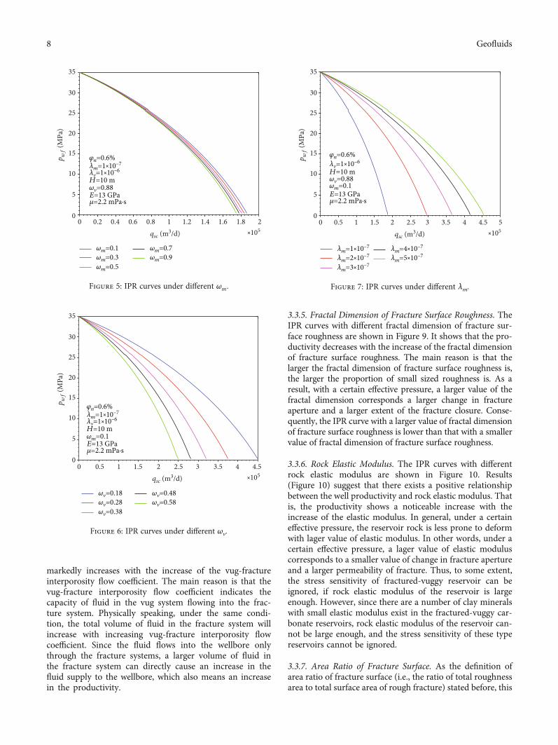
3.3.1. Elastic Storage Capacity Ratio of Matrix. The IPRcurves with different matrix elastic storage capacity ratiosare shown in Figure 5. It shows that the productiondecreases slightly with the increase of matrix elastic storage
capacity ratio. A possible explanation for this is that thematrix system elastic storage capacity ratio reflects its rela-tive storage capacity compared with those of fracture systemand vug system. Mathematically speaking, under a given vugelastic storage capacity, a higher matrix elastic storage capac-ity means a relative lower fracture storage capacity. Since thefracture is the main flow channel for fluid flow, lower frac-ture storage capacity will cause a decrease in the efficiencyof fluid supply to the wellbore.
3.3.2. Elastic Storage Capacity Ratio of Vug. The IPR curveswith different elastic storage capacity ratios of vug are shownin Figure 6. It shows that the productivity decreases largelywith the increase of the elastic storage capacity ratio ofvug. Generally speaking, the elastic storage capacity ratio ofvug reflects its larger relative storage capacity compared withthose of the fracture system and matrix system. That is,under a given matrix elastic storage capacity, a higher valueof elastic storage capacity ratio of the vug system is alwaysaccompanied by a lower value of fracture storage capacity.Thus, there exists a negative relationship between the pro-ductivity and the elastic storage capacity ratio of the vugsystem.
3.3.3. Matrix-Fracture Interporosity Flow Coefficient. TheIPR curves with different matrix-fracture interporosity flowcoefficients are shown in Figure 7. It shows that the produc-tivity increases with the increase of the matrix-fracture inter-porosity flow coefficient. This can be explained by the factthat a larger matrix-fracture interporosity flow coefficientmeans a stronger flow capacity from the matrix into the frac-ture, which can improve the fluid supply capacity of fracturesystem to the wellbore, thereby increasing the productivity.
3.3.4. Vug-Fracture Interporosity Flow Coefficient. The IPRcurves with different vug-fracture interporosity flow coeffi-cients are shown in Figure 8. It can be seen from Figure 8that, when other parameters are fixed, the productivity
0.5 1 1.5 2 2.5 3 3.5 4 4.5⨯105
qsc (m3 d)
00
5
10
15
20
25
30
35
pwf
(MPa
)
𝜔m=0.1𝜔v=0.88
𝜆m=1⨯10–7
𝜆v=1⨯10–6
H=10 m
𝜑n=0.6%
E=13 GPa𝜇=2.2 mPa·s
Production with stress sensitivity consideredProduction without stress sensitivity considered
Figure 4: The impact of effective stress on IPR curves.
7Geofluids
markedly increases with the increase of the vug-fractureinterporosity flow coefficient. The main reason is that thevug-fracture interporosity flow coefficient indicates thecapacity of fluid in the vug system flowing into the frac-ture system. Physically speaking, under the same condi-tion, the total volume of fluid in the fracture system willincrease with increasing vug-fracture interporosity flowcoefficient. Since the fluid flows into the wellbore onlythrough the fracture systems, a larger volume of fluid inthe fracture system can directly cause an increase in thefluid supply to the wellbore, which also means an increasein the productivity.
3.3.5. Fractal Dimension of Fracture Surface Roughness. TheIPR curves with different fractal dimension of fracture sur-face roughness are shown in Figure 9. It shows that the pro-ductivity decreases with the increase of the fractal dimensionof fracture surface roughness. The main reason is that thelarger the fractal dimension of fracture surface roughness is,the larger the proportion of small sized roughness is. As aresult, with a certain effective pressure, a larger value of thefractal dimension corresponds a larger change in fractureaperture and a larger extent of the fracture closure. Conse-quently, the IPR curve with a larger value of fractal dimensionof fracture surface roughness is lower than that with a smallervalue of fractal dimension of fracture surface roughness.
3.3.6. Rock Elastic Modulus. The IPR curves with differentrock elastic modulus are shown in Figure 10. Results(Figure 10) suggest that there exists a positive relationshipbetween the well productivity and rock elastic modulus. Thatis, the productivity shows a noticeable increase with theincrease of the elastic modulus. In general, under a certaineffective pressure, the reservoir rock is less prone to deformwith lager value of elastic modulus. In other words, under acertain effective pressure, a lager value of elastic moduluscorresponds to a smaller value of change in fracture apertureand a larger permeability of fracture. Thus, to some extent,the stress sensitivity of fractured-vuggy reservoir can beignored, if rock elastic modulus of the reservoir is largeenough. However, since there are a number of clay mineralswith small elastic modulus exist in the fractured-vuggy car-bonate reservoirs, rock elastic modulus of the reservoir can-not be large enough, and the stress sensitivity of these typereservoirs cannot be ignored.
3.3.7. Area Ratio of Fracture Surface. As the definition ofarea ratio of fracture surface (i.e., the ratio of total roughnessarea to total surface area of rough fracture) stated before, this
0.2 0.4 0.6 0.8 1 1.2 1.4 1.6 1.8 2⨯105
qsc (m3/d)
𝜔v=0.88
𝜔m=0.1𝜔m=0.3
𝜔m=0.7𝜔m=0.9
𝜔m=0.5
𝜆m=1⨯10–7
𝜆v=1⨯10–6
H=10 m
𝜑n=0.6%
E=13 GPa𝜇=2.2 mPa·s
00
5
10
15
20
25
30
35
pwf
(MPa
)
Figure 5: IPR curves under different ωm.
0.5 1 1.5 2 2.5 3 3.5 4 4.5⨯105
qsc (m3/d)
𝜔v=0.18𝜔v=0.28
𝜔v=0.48𝜔v=0.58
𝜔v=0.38
00
5
10
15
20
25
30
35
pwf
(MPa
)
𝜔m=0.1
𝜆m=1⨯10–7
𝜆v=1⨯10–6
H=10 m
𝜑n=0.6%
E=13 GPa𝜇=2.2 mPa·s
Figure 6: IPR curves under different ωv.
0.5 1 1.5 2 2.5 3 3.5 4 4.5 5⨯105
qsc (m3/d)
𝜆m=1⨯10–7
𝜆m=2⨯10–7𝜆m=4⨯10–7
𝜆m=5⨯10–7
𝜆m=3⨯10–7
𝜔v=0.88𝜔m=0.1
𝜆v=1⨯10–6
H=10 m
𝜑n=0.6%
E=13 GPa𝜇=2.2 mPa·s
00
5
10
15
20
25
30
35
pwf
(MPa
)
Figure 7: IPR curves under different λm.
8 Geofluids

parameter can be used to characterize the microstructure offracture surface. Figure 11 shows the influence of area ratioof fracture surface on IPR curves. It can be seen that the pro-ductivity increases with the increasing area ratio of fracturesurface. Physically speaking, a larger value of area ratio of frac-ture surface corresponds to a smaller the proportion of smallsized roughness. Thus, under a given overburden pressure(or effective pressure), with the increase of area ratio of frac-ture surface, the move distance of fracture surfaces decreases,resulting in a smaller extent of the fracture closure and a largerpermeability of fracture system. As a result, IPR curve with alarger value of area ratio of fracture surface is higher than thatwith a smaller value of area ratio of fracture surface.
4. Discussions
Eq. (14) illustrates that, except for the parameter D, the IPRcurves of fractured-vuggy carbonate reservoirs are identicalto the normal Darcy’s IPR curves generated for single con-tinuum reservoir. Thus, if the parameter D is assigned asunity, the IPR curves of fractured-vuggy carbonate reservoirscan be simplified as the normal Darcy’s IPR curves gener-ated for single continuum reservoir. As a result, parameterD can be regarded as a parameter representing of how easythe fluid can move from one system to the others. In thispaper, we ignore the fluid flow within the matrix systemand assume that only the fracture system is directly con-nected with the wellbore. However, if the permeability of
2 4 6 8 10 12 14 16 18⨯104
qsc (m3/d)
𝜆v=1⨯10–8
𝜆v=2⨯10–8𝜆v=4⨯10–8
𝜆v=5⨯10–8
𝜆v=3⨯10–8
𝜔v=0.88𝜔m=0.1
𝜆m=1⨯10–7
H=10 m
𝜑n=0.6%
E=13 GPa𝜇=2.2 mPa·s
00
5
10
15
20
25
30
35
pwf
(MPa
)
Figure 8: IPR curves under different λv.
0.2 0.4 0.6 0.8 1 1.2 1.4 1.6 1.8 2⨯105
qsc (m3/d)
DR=0.1DR=0.3
DR=0.7DR=0.9
DR=0.5
00
5
10
15
20
25
30
35
pwf
(MPa
)
𝜔v=0.88𝜔m=0.1
𝜆m=1⨯10–7
𝜆v=1⨯10–6
H=10 m
𝜑n=0.6%
E=13 GPa𝜇=2.2 mPa·s
Figure 9: IPR curves under different DR.
0.5 1 1.5 2 32.5⨯105
qsc (m3/d)
E=10 GPaE=15 GPa
E=25 GPaE=30 GPa
E=20 GPa
00
5
10
15
20
25
30
35
pwf
(MPa
)
𝜔v=0.88𝜔m=0.1
𝜆m=1⨯10–7
𝜆v=1⨯10–6
H=10 m
𝜑n=0.6%
𝜇=2.2 mPa·s
Figure 10: IPR curves under different E.
0.5 1 1.5 2 32.5⨯105
qsc (m3/d)
𝜑n=0.6%𝜑n=0.8%
𝜑n=1.2%𝜑n=1.4%
𝜑n=1.0%
𝜔v=0.88𝜔m=0.1
𝜆m=1⨯10–7
𝜆v=1⨯10–6
H=10 m
E=13 GPa𝜇=2.2 mPa·s
00
5
10
15
20
25
30
35pwf
(MPa
)
Figure 11: IPR curves under different φn.
9Geofluids

the matrix system is not small enough, we can modify themodel and take the fluid flow in matrix system into account.In that case, we just need to modify parameter D. Physicallyspeaking, parameter D accounts for the pressure drop thatoccurs due to the crossflow between different systems inthe reservoirs. In the normal straight line IPR model, weignore the crossflow between different systems and only con-sider the radial flow pressure drop. In other words, when thevalue of parameter D approaches unity, the IPR curve will goup due to the reduction in the pressure drop caused bycrossflow between different systems.
As stated by Youssef [47], if we take the effect of damagezone with small radius around wellbore into account, Eq.(14) can be modified as
J = qsc�p − pwf
=2πKfHD
μB ln re/rwð Þ − 3/4 + s½ � , ð24Þ
where parameter s is the skin factor.However, it should be noted that Eq. (24) is based on the
assumption that the damaged zone only affects the radialflow and has nothing to do with the crossflow between dif-ferent systems. That is, the damaged zone has little influenceon parameter D. Physically, parameter D will be affected bythe damaged zone. In our future work, we will further studythe effect of damaged zone on parameter D.
5. Summary and Conclusions
In this paper, based on fractal theory, a theoretical model forstress-dependent permeability of rough fracture is devel-oped. Then, by coupling flow equations in triple media,and the derived fracture permeability model, a new produc-tivity prediction model for fractured-vuggy reservoir underpseudosteady state is established. Compared with formermodels, the derived models in this work account for com-plex morphology of rough fracture, fracture closure due toeffective stress, and crossflow between different systems inthe fractured-vuggy carbonate reservoirs. In addition, everymodel parameter in this work has exact physical meaning.Followings are the main conclusions:
(1) The influence of effective stress on well productivityis significant, and it will become stronger as thedevelopment progresses. Thus, our derived modelcan help to predict the well productivity more accu-rately with lower the uncertainty
(2) Compared with matrix elastic storage capacity ratio,the elastic storage capacity ratio of vug will have agreater impact on well productivity. It is found thathigher elastic storage capacity ratio of vug will causea decrease in the well production. However,increases in both matrix-fracture interporosity flowcoefficient and vug-fracture interporosity flow coeffi-cient will increase the well production, which wasanticipated
(3) It is worth noting that the model is established onthe assumption of evenly distributed matrix, fracturesystem, and vug system, which is largely simplifiedthan real reservoir situation. In addition, the modelis limited to single phase flow, which ignores theinteraction between multiple phases. To betterunderstand the well productivity in fractured-vuggyreservoirs, more works are needed to be done. Inour future work, the derived model will be extendedto multiple phases flow in the fractured-vuggyreservoirs
Appendix
A
Based on the assumption that the fracture with rough sur-faces can be simplified as smooth surfaces with rough cylin-drical shaped fractal elements, the total number of all theseelements on the surface can be expressed as [41–45]
N = lmax/lminð ÞDR : ðA:1Þ
Then, the probability density function for the elementscan be written as follows [41]:
f lð Þ =DRlDRminl
− DR+1ð Þ, ðA:2Þ
where l is the length of the rough element.Based on Eqs. (16), (A.1), and (A.2), the total area of the
rough elements can be calculated by
S =Nð lmax
lmin
πr2 f dl = DRπlDRmax
ε2 2 −DRð Þ l2−DRmax − l2−DR
min
� �, ðA:3Þ
where ε is a constant ratio of the length to the radius ofthe elements. Τhen, the area of the roughened fracturesurface is
A = Sφn
= DRπlDRmax
ε2φn 2 −DRð Þ l2−DRmax − l2−DR
min
� �: ðA:4Þ
Based on Hook’s Law, the distance x of the fracturesurfaces moving towards each other changes with the forceF exerting on fractures as [11, 19]
F xð Þ =ðN xð Þ
N 0ð ÞτR x − βð ÞdN βð Þ, ðA:5Þ
with
R x − βð Þ =x − β x > β,0 x < β,
(ðA:6Þ
where β is the rough element’s shortness, μm; τ is therough element’s spring constant.
10 Geofluids

Physically speaking, based on the elastic theory, therough element’s spring constant is [11, 19]
τ = Eπr2
l= Eπ ω0 − βð Þ
ε2: ðA:7Þ
Then, by combining Eqs. (A.4) through (A.7), the effec-tive stress exerting on the fracture surfaces is [11, 39]
pef f =FA
= EπDR ω0 − βminð ÞDR
Aε2⋅ x − ω0ð Þω
1−DR0 − ω0 − xð Þ1−DR
1 −DR
"
+ ω2−DR0 − ω0 − xð Þ2−DR
2 −DR
#= Eφn 2 −DRð Þ
l2−DRmax − l2−DR
min
� �
⋅ x − ω0ð Þω1−DR0 − ω0 − xð Þ1−DR
1 −DR
"
+ ω2−DR0 − ω0 − xð Þ2−DR
2 −DR
#:
ðA:8Þ
Nomenclature
Latin Symbols
A: Area of fracture surface, μm2
B: Fluid bulk coefficient, m3/m3
C: Compressibility coefficient, MPa-1
D: Modified parameter, dimensionlessDR: Fractal dimension for fracture surface roughnessE: Rock elastic modulus, GPaF: Force exerting on the fracture, MPaH: Reservoir effective sickness, mJ : Production indexK : Permeability, μm2
�K : Average permeability of the reservoirKf 0: Initial permeabilityKf : Stress-dependent permeabilityl: Length of the rough element, μmN : Total number of all these elements on the surfacep: Formation pressure, MPapef f : Effective stress, MPapwf : Bottom hole pressure, MPaqsc: Productivity at ground standard condition, m3/dr: Distance, mre: Radius of the reservoir, mrw: Wellbore radius, mS: Total area of the rough elementss: Skin factor, dimensionlesst: Production time, dVB: Fluid volume at formation condition, m3.
Greek Symbols
α: Shape factor, m-2
β: Rough element’s shortness, μm
ε: Constant ratio of the length to the radius of the ele-ments, dimensionless
μ: Fluid viscosity, mPa·sφ: Porosity, %φn: Ratio of total roughness area to total surface area of
rough fracture, dimensionlessλ: Interflow coefficient, dimensionlessω: Elastic storage capacity ratioω0: Initial fracture aperture, μmτ: Rough element’s spring constant.
Subscripts
B: Formation conditioneff: Effectivef : Fracturesm: Matrixmax: Maximum valuesmin: Minimum valuesn: Total roughnessv: VugsR: Roughness.
Data Availability
All data included in this study are available upon request bycontact with the corresponding author.
Conflicts of Interest
The authors declare that they have no conflicts of interest.
Acknowledgments
The authors are grateful for the financial support from theProject of the State Key Laboratory of Shale Oil and GasEnrichment Mechanisms and Effective Development(10010099-19-ZC0607-0042).
References
[1] L. I. Yang, K. A. Zhijiang, X. U. Zhaojie, and S. Zheng, “Theo-ries and practices of carbonate reservoirs development inChina,” Petroleum Exploration and Development, vol. 45,no. 4, pp. 669–678, 2018.
[2] Ministry of Natural Resources of the People's Republic ofChina, “National report on exploration and exploitation ofpetroleum and natural gas resources,” 2019, http://gi.mnr.gov.cn/201907/t20190715_2447470.html.
[3] C. Xunyu, L. Jinlian, Z. Peirong, L. Chaoying, and C. Zhe, “Oiland gas exploration progress and upstream development strat-egy of Sinopec,” China Petroleum Exploration, vol. 25, no. 1,pp. 11–19, 2020.
[4] X. Wang, “New prospect of Sinopec gas exploration,” SinopecMonthly, vol. 9, no. 9, pp. 43-44, 2017.
[5] X. Lyu, Z. Liu, J. Hou, and T. Lyu, “Mechanism and influenc-ing factors of EOR by N2 injection in fractured-vuggy carbon-ate reservoirs,” Journal of Natural Gas Science andEngineering, vol. 40, pp. 226–235, 2017.
11Geofluids

[6] G. Lei, Q. Liao, and D. Zhang, “A new analytical model for flowin acidized fractured-vuggy porous media,” Scientific Reports,vol. 9, p. 8293, 2019.
[7] W. Yang, D. Zhang, and G. Lei, “Experimental study on mul-tiphase flow in fracture-vug medium using 3D printing tech-nology and visualization techniques,” Journal of PetroleumScience and Engineering, vol. 193, article 107394, 2020.
[8] Y. Feng, Y. Liu, and G. Lei, “Study on stress-dependent perme-ability of fracture networks in fractured porous media,” Geo-fluids, vol. 2021, Article ID 7433547, 19 pages, 2021.
[9] F. Yan, Y. Kang, and S. Li, “Simulated experiment on stresssensitivity in fractured-vuggy reservoir,” Natural Gas Geosci-ence, vol. 21, no. 3, pp. 489-490, 2010.
[10] N. Cao and G. Lei, “Stress sensitivity of tight reservoirs duringpressure loading and unloading process,” Petroleum Explora-tion and Development, vol. 46, no. 1, pp. 132–138, 2019.
[11] G. Lei, N. Cao, and Q. Wen, “Permeability prediction inroughened fractures under stress condition using fractalmodel,” Fractals, vol. 27, no. 3, article 1950030, 2019.
[12] L. Zhang, F. Zhou, J. Mou, J. Wang, J. Wang, and S. Zhang,“Research on sensitivity damage of naturally fractured carbon-ate reservoirs in Ordos Basin,” Arabian Journal of Geosciences,vol. 12, no. 18, pp. 1–7, 2019.
[13] G. Lei, Q. Liao, and S. Patil, “A fractal model for relative per-meability in fractures under stress dependence,” Fractals,vol. 27, no. 6, article 1950092, 2019.
[14] N. Bo, X. Zuping, L. Xianshan et al., “Production predictionmethod of horizontal wells in tight gas reservoirs consideringthreshold pressure gradient and stress sensitivity,” Journal ofPetroleum Science and Engineering, vol. 187, article 106750,2020.
[15] C. R. Mckee, A. C. Bumb, and R. A. Koenig, “Stress-dependentpermeability and porosity of coal and other geologic forma-tions,” SPE Formation Evaluation, vol. 3, no. 1, pp. 81–91,1988.
[16] P. D. Mckinney, J. A. Rushing, and L. A. Sanders, “Applied res-ervoir characterization for maximizing reserve growth andprofitability in tight gas sands: a paradigm shift in develop-ment strategies for low-permeability gas reservoirs,” in PaperSPE-75708-MS presented at the SPE Gas Technology Sympo-sium, Calgary, Alberta, Canada, 2002.
[17] R. A. Archer, “Impact of stress sensitive permeability on pro-duction data analysis,” in Paper SPE-114166-MS presented atthe SPE Unconventional Reservoirs Conference, Keystone, Col-orado, USA, 2008.
[18] S. Zhu, “Experiment research of tight sandstone gas reservoirstress sensitivity based on the capillary bundle model,” inPaper SPE-167638-STU presented at the SPE Annual TechnicalConference and Exhibition, New Orleans, Louisiana, USA,2013.
[19] A. F. Gangi, “Variation of whole and fractured porous rockpermeability with confining pressure,” International Journalof Rock Mechanics and Mining Sciences & GeomechanicsAbstracts, vol. 15, no. 5, pp. 249–257, 1978.
[20] S. R. Brown and C. H. Scholz, “Broad bandwidth study ofthe topography of natural rock surfaces,” Journal of Geo-physical Research: Solid Earth, vol. 90, no. B14, pp. 12575–12582, 1985.
[21] L. Lan, Research on Stress Sensitivity and Prediction of FractureWidth in Naturally Fractured Sandstone Reservoirs, Masterthesis of Chengdu: Southwest Petroleum Institute, 2005.
[22] N. Cao, G. Lei, P. Dong, H. Li, Z. Wu, and Y. Li, “Stress-depen-dent permeability of fractures in tight reservoirs,” Energies,vol. 12, no. 1, p. 117, 2019.
[23] C. Zhang, Y. Chen, Z. Deng, andM. Shi, “Role of rough surfacetopography on gas slip flow in microchannels,” PhysicalReview E, vol. 86, no. 1, article 016319, 2012.
[24] C. Wang, Construction theory and method of dual pore net-work model in carbonate media, PhD thesis of China Univer-sity of Petroleum East China, 2013.
[25] L. B. Neto, A. Kotousov, and P. Bedrikovetsky, “Elastic proper-ties of porous media in the vicinity of the percolation limit,”Journal of Petroleum Science and Engineering, vol. 78, no. 2,pp. 328–333, 2011.
[26] A. Sharma, Shape Factors for the Pseudo-Steady State Flow inFractured HydrocarbonWells of Various Drainage Area Geom-etries, Master thesis of Arizona State University, 2017.
[27] R. Jadidi, R. Sedaee, S. Gerami, and A. Nakhaee, “Developmentof production data analysis models for multi-well gas conden-sate reservoirs,” Journal of Petroleum Science and Engineering,vol. 202, article 108552, 2021.
[28] H. Belyadi, E. Fathi, and F. Belyadi, Hydraulic Fracturing inUnconventional Reservoirs (Second Edition), Gulf ProfessionalPublishing, Oxford, 2019.
[29] B. Guo, X. Liu, and X. Tan, Petroleum Production Engineering,(Second Edition), Gulf Professional Publishing, Oxford, 2017.
[30] M. Dejam, H. Hassanzadeh, and Z. Chen, “Semi-analyticalsolutions for a partially penetrated well with wellbore storageand skin effects in a double-porosity system with a gas cap,”Transport in Porous Media, vol. 100, no. 2, pp. 159–192, 2013.
[31] G. Lei, P. Dong, and S. Yang, “Productivity analysis of tightsandstone gas reservoir in pseudo-steady state,” PetroleumGeology and Recovery Efficiency, vol. 21, no. 5, pp. 94–97, 2014.
[32] G. Lei, R. Dong, S. Yang, and Z. Li, “Productivity analysis of ofthe vertically fractured wells in pseudo-steady state for tightsandstone gas reservoirs,” Petroleum Geology and OilfieldDevelopment in Daqing, vol. 33, no. 1, pp. 170–174, 2014.
[33] M. Morgan, “Forecasting tight gas well production with amaterial balance constraint,” in Paper SPE-137825-PP pre-sented at the Canadian Unconventional Resources & Interna-tional Petroleum Conference, Calgary, Alberta, Canada, 2010.
[34] C. Zhang, P. Wang, B. Guo, and G. Song, “Analytical modelingof productivity of multi-fractured shale gas wells underpseudo-steady flow conditions,” Energy Science & Engineering,vol. 6, no. 6, pp. 819–827, 2018.
[35] S. Al-Rbeawi, “Pseudo-steady state inflow performance rela-tionship of reservoirs undergoing multiphase flow and differ-ent wellbore conditions,” Journal of Natural Gas Science andEngineering, vol. 68, article 102912, 2019.
[36] A. A. Youssef and S. Alnumaim, “IPR of triple continuum res-ervoirs, analytical approach,” in Paper SPE-187973-MS pre-sented at the SPE Kingdom of Saudi Arabia Annual TechnicalSymposium and Exhibition, Dammam, Saudi Arabia, 2017.
[37] Y. Wu, Y. di, Z. Kang, and P. Fakcharoenphol, “A multiple-continuum model for simulating single-phase and multiphaseflow in naturally fractured vuggy reservoirs,” Journal of Petro-leum Science and Engineering, vol. 78, no. 1, pp. 13–22, 2011.
[38] Y. S. Wu, C. A. Ehlig-Economides, G. Qin et al., “A triple-continuum pressure-transient model for a naturally fracturedvuggy reservoir,” in Paper SPE-110044-MS presented at theSPE Annual Technical Conference and Exhibition, Anaheim,California, U.S.A, 2007.
12 Geofluids

[39] G. Stewart,Well test design & analysis, PennWell Corporation,Tulsa, 2011.
[40] P. Q. Lian, L. S. Cheng, L. L. Li, and Z. Li, “The variation law ofstorativity ratio and interporosity transfer coefficient in frac-tured reservoirs,” Engineering Mechanics, vol. 28, no. 9,pp. 240–244, 2011.
[41] B. Yu and J. Li, “Some fractal characters of porous media,”Fractals, vol. 9, no. 3, pp. 365–372, 2001.
[42] H. Singh and J. Cai, “A feature-based stochastic permeabilityof shale: part 2-predicting field-scale permeability,” Transportin Porous Media, vol. 126, pp. 561–578, 2019.
[43] J. Cai, W. Wei, X. Hu, R. Liu, and J. Wang, “Fractal character-ization of dynamic fracture network extension in porousmedia,” Fractals, vol. 25, no. 2, article 1750023, 2017.
[44] G. Lei, C. Wang, Z. Wu, H. Wang, andW. Li, “Theory study ofgas-water relative permeability in roughened fractures,” Pro-ceedings of the Institution of Mechanical Engineers, Part C:Journal of Mechanical Engineering Science, vol. 232, no. 24,pp. 4615–4625, 2018.
[45] Y. Chen, P. Fu, C. Zhang, and M. Shi, “Numerical simulationof laminar heat transfer in microchannels with rough surfacescharacterized by fractal cantor structures,” International Jour-nal of Heat and Fluid Flow, vol. 31, no. 4, pp. 622–629, 2010.
[46] J. Lu and S. Ghedan, “Pseudo-steady state productivity equa-tions for a multiple-wells system in a sector fault reservoir,”in Paper SPE-130866-MS presented at the SPE EUROPEC/E-AGE Annual Conference and Exhibition, Barcelona, Spain,2010.
[47] A. A. Youssef, “Inflow performance relationship of verticalwells in fractured vuggy media during semi-steady state flowregime,” Journal of Petroleum Science & Engineering,vol. 176, pp. 970–981, 2019.
13Geofluids


![Predicting the Permeability of Fractured Porous Rock · permeability of fractured porous media is still required to study. Lorente et al. [1] studied the characteristics of fractured](https://img.pdfslide.us/doc/110x75/5f7848dc5e4d3a12c462bb61/predicting-the-permeability-of-fractured-porous-rock-permeability-of-fractured-porous.jpg)