Embed Size (px)
Citation preview

A New Method to Make Communication Latency Uniform: Distributed Routing Balancing
D.Franco, I.Garc&, E.Luque
Unitat d’Arquitectura d’ordinadors i Sistemes Operatius - Departament d’lnform&tica Universitat Autbnoma de Barcelona - 08193-Bellaterra, Barcelona, Spain
{d.franco, iarq23, e.luaueI@ cc.uab.es http://aowsl .uab.es
ABSTRACT
We have developed a new method to uniformly balance communication traffic over the interconnection network called Distributed Routing Balancing (DRB) that is based on limited and load-controlled path expansion in order to maintain a low message latency. DRB defines how to create alternative paths to expand single paths (expanded path definition) and when to use them depending on traffic load (expanded path selection carried out by DRB Routing). The alternative path definition offers a broad range of alternatives to choose from and the DRB Routing is designed with the goal of minimising monitoring and decision overhead. Evaluation in terms of latency and bandwidth is presented. Some conclusions from the experimentation and comparisons with existing methods are given. It is demonstrated that DRB is a method to effectively balance network traffic.
Keywords
Interconnection networks, adaptive routing, random routing, hot spot avoidance, traffic distribution, uniform latency, distributed routing balancing.
1. INTRODUCTION We shall start by describing the typical behaviour pattern
observed when common programs, such as those from mathematical applications are run on a parallel computer interconnection network. In such networks the parallel program running on the parallel machine is described as a collection of processes and channels and there is a mapping which assigns each process to a processor. Processes execute concurrently and communicate by logical channels.
Generally, it is observed that saturation occurs at low load communication rates (commonly less than 50% of the network maximum capacity) and it appears very suddenly (latency takes impracticable values). Such communication latency needs to be avoided in order to make communications faster and reduce the total execution time of the program. However, it is in fact more important to avoid big latency variations than any given amount
permission to make digital or hard topics of all or part of this work fol personal or classroom use is granted without fee provided that copies are not made or distributed for profit or commercial advantage and that copies hear this notice and the full citation on the tirst page. To cWY othcnvise, to rcpubljsh, to post on servers or to rcdktributc to liStS, reqtlires prior specific permission and/or a fee. ICS ‘99 Rhodes Greece Copfight ACM 1999 l-581 13-164-x/99/06...$5.00
of latency. The reason is because a bounded amount oflatency can be tolerated by hiding it through the method of assigning an “excess” of parallelism, i.e. having enough processes per processor, and scheduling any ready process while other processes wait for their messages. But, if latency undergoes big unpredictable variations from the expected values (due to hot spots, for example), idle processors will appear because all their processes are blocked, waiting for their corresponding messages, and, consequently, the total execution time of the application is increased.
The low load saturation phenomenon, typical of interconnection networks, is due to the appearance of hotspots and their concomitant characteristics: exponential domino effect and fast propagation. A sustained message contention situation can produce hot-spots [ 151. A hot spot is a region of the network that is saturated, (i.e. there exists more bandwidth demand than the network can offer) and, then, messages that enter this region suffer a very high latency while other regions of the network are less loaded and have bandwidth available. The problem is that there is an incorrect communication load distribution over the network topology and that, although the total communication bandwidth requirements do not surpass the total bandwidth offered by the interconnection network, this uneven distribution generates saturated points as if the whole interconnection network were collapsed. Saturation is produced when the buffers of the routers in the hot-spot region are full, while other network regions have free resources. In addition, the hot-spot situation propagates rapidly to contiguous areas in a domino eff&t, which can collapse the whole interconnection network rapidly. This effect is even worse in the case of wormhole routing because a blocked packet occupies a large number of links spread in thi network. Nowadays, in order to maintain a low and stable latency, networks are operated at low load to avoid hot-spot generation. This fact leads to an under-use of the network.
Therefore, these hot spots are produced because there is an imbalance of communication load in the network links. This imbalance is produced by the application communication pattern that is non-uniform.
Many mechanisms have been developed to avoid hot-spot generation due to message contention in interconnection networks, such as the dynamic routing algorithms that try to adapt to traffic conditions. Some examples are Planar Adaptive Routing [4], the Turn Model [14], Duato’s Algorithm [8], Compressionless Routing [l 11, Chaos Routing [12], Random Routing [18] [ 131 and other methods presented in [9]. The main disadvantages of adaptive routing are the high overheads
210
resulting from information monitoring, path changing and the necessity to guarantee deadlock, live-lock and starvation freedom. These drawbacks have limited the implementation of these techniques in commercial machines.
We have developed a new method which, taking into account the above considerations, performs a communication load balancing in order to move message flows from the most loaded to less loaded links. The method is called Distributed Routing Balancing (DRB). DRB can be paralleled to Dynamic Load Balancing, which “moves” computation loads (processes) from one processor to another.
Using previous works about random routing as a springboard, Valiant [IS] and Welch [ 131, DRB creates new alternative paths between each source- destination pair when the current path is becoming saturated. The new paths are less loaded and the global effect is a uniform communication load distribution over all links of the interconnection networks.
DRB’s objectives are to maintain controlled and uniform latency and, thus, allow a higher use of the interconnection network since saturation occurs at higher communication load rates.
The work presented in this paper focuses on developing a new method to distribute messages in the interconnection network using network-load controlled path expansion. The method’s objective is to uniformly balance traffic load over all paths of the whole interconnection network. The method is based on creating, under certain load values, simultaneous alternative paths between each source and destination node in order to enable an increase in bandwidth use and to maintain a low message latency. DREI defines how to create alternative paths to expand single paths (multi-lane path definition) and when to use them, depending on traffic load (multi-lane path selection).
The method offers a broad range of alternatives that move from minimal static to random routing methods. In fact, both static and random routings are included in the DRB specification as particular cases.
The next two sections explain the Distributed Routing Balancing technique. DRB has two components: first, a systematic methodology to generate multi-lane paths according to the network topology and second, a routing algorithm to monitor traffic load and select multi-lane paths to get the message distribution according to traffic load. Section 2 gives some concept definitions and the multi-lane path generation methodology. Section 3 presents the DRB Routing algorithm. Section 4 shows the evaluation of the DRB method carried out by experimentation with a network simulator. Section 5 presents a discussion of the method and comparison with other existing methods. Finally, section 6 presents the conclusions and future work.
2. DISTRIBUTED ROUTING BALANCING Distributed Routing Balancing is a method of creating
alternative source-destination paths in the interconnection network using a load-controlled path expansion. DRB distributes every source-destination message load over a “multi- lane path” made of several paths. This distribution is controlled by the path load level. The objective of DRJ3 is a uniform
distribution of the traffic load over the whole interconnection network in order to maintain a low message latency and avoid the generation of hot-spots. This message distribution will maintain , a uniform and low latency in the whole interconnection network provided that total communication bandwidth demand does not exceed interconnection network capacity. In addition, due to hot-spot avoiding, network throughput is increased and the network is allowed to be used at higher average load rates. Depending on the traffic load and its distribution pattern, the DRB method configures paths to distribute load from more loaded to less loaded paths.
The method’s principal idea is based on message latency behaviour according to message traffic load level in interconnection networks. The typical behaviour has been studied by many authors [I], [7], [9]. It can be represented by a non-lineal curve in which two regions can be identified: first, a flat region at low-load level with near-linear behaviour (where big changes in the communication load cause small changes in latency) and, second, a sharp rise from a threshold load level (where small changes in the communication load cause big changes in latency). Also, a threshold latency value can be identified where the curve changes from the flat to the rise region. This Threshold Latency (ThL) is the point of the curve with the minimum radius of curvature.
The sharp slope curve pattern is not desirable because it means latency is not stable and undergoes big changes in relation to small traffic load changes. According to the latency behaviour, the DRB method moves the working point of the congested area from the saturation point to a lower latency point in the flat region of the curve. This effect is achieved by modifying path distribution to reduce traffic on the most loaded paths. The result is big latency reductions on congested paths and small latency increments on non-congested paths because they still have some bandwidth available and, therefore, the global effect is positive. The resulting latency configuration is uniform and low for all paths.
The DRB method fulfils the following objectives: 1. Reduction of the message latency under a certain threshold
value by dynamically varying the number of alternative paths used by the source-destination pair, while maintaining a uniform latency for all messages. This is achieved by maximising the use of the interconnection network resources in order to minimise communication delays.
2. Minimisation of path-lengthening. This point is important for Wormhole and Cut-Through flow controls because two main latency factors, bandwidth use and collision points, are increased. For Store&Forward networks it is also important because Transmission Delay depends directly on the length of the message path.
3. Maximisation of the use of the source and destination node links (node grade), distributing messages fairIy over all processor links.
The path expansion is achieved by selecting intermediate nodes to which send the messages before sending them to their final destination. The method selects two nodes in order to avoid a saturated original static path between two nodes, source A and destination B. One node, X, is selected from a set
211
surrounding the source node A and another, Y, from a set surrounding the destination node B. Then the message is sent from A to X, then to Y and then to B following the path A-X-Y- B. This new path is selected because it is less loaded than the original one. This procedure is repeated for each message and for each source-destination pair.
In order to show how DRB works to create and use the alternative paths, we make the following definitions:
Definition 0: l An Interconnection Network I is defined as a directed
graph I=(N,E), where N is a set of nodes MaxN
N= UN, andE a set of arcs connecting pairs of i=o
nodes. Usually, every node is composed of a router and is connected to other nodes by means of links, represented by the arcs. The topology can be regular or irregular depending on the network. For example, for k- ary n-cubes [6], n is the dimension and k the size.
. If two nodes Ni and Nj are directly connected by a
link, then, Ni and Nj are adjacent nodes.
l Distancec Ni , Nj) is the minimum number of links
that must be crossed to go from Ni to Nj according to the Graph 1.
. A path P( Ni , Nj ) between two nodes Ni and Nj
is the set of nodes selected between
Ni and Nj according to the minimal static routing
defined for the interconnection network (for example,
Dimensional Order Routing for k-ary n-Cubes). Ni is
the source node and Nj the destination node. Length
of a path P, Length(P), is the number of links between
Ni and Nj following the defined routing. In case of
minimal static routing:
Lengtk(P( Ni , Nj ) ) = Distance( Ni , Nj ) [I ]
Definition 1:
A Supernode S(type, size, N,S) = Ifi NY, is defined as a i=O
structured region of the interconnection network consisting of I
adjacent nodes N,? around a “central” node N,S provided
that: N,? complies with a given property specified in type and
Distance ( Nf , N,S ) <=size.
As particular cases, any single node and the whole interconnection network are Supemodes. A Supemode that contains only a single node is called a minor canonical form; if a Supernode contains all the nodes in the network it is called a major canonical form. A node can belong to more that one Supemode.
DRB defines two different Super-node types suitable for any
topology. The first one is called Gravity Area and the second Subtopology. The parameters type and size of the Supernode determine which nodes are included in the Supemode and also the following properties: Topological shape, number of nodes 1,
Supernode Grade (number of Ni node links not connected to
other Ni node links, i.e. links connected outside the
Supernode), number of Supemode nodes connected to N,S . Gravity Area Supernode: A Gravity Area Supernode
S(“Gravity Area”, size, N,S) is the set of nodes at a distance
from the node N,S smaller or equal to the size. This type
expands the Supernode selecting the higher number of nodes surrounding the central node. It is suitable for regular or irregular networks.
Subtopology Supernode: A Supemode S(“Subtopology”,
size, N,S ) has the same full/partial topological shape as the
interconnection network but its dimension and/or size is reduced. Therefore, the Subtopology Supernode should be considered as a kind of topological “projection” of the network topology. It can be applied to regular networks with a structured topology, dimension and size. For example, in a k- ary n-cube a Subtopology Supernode is any j-ary m-cube with j<k and/or m<n.
A more detailed description of these Supernode types for k- ary n-cubes [6] and Midimew networks [2] and the evaluation of their above mentioned properties can be found in [ 1 O].
Definition 2:
A Multi-step Path MSP(SOrigin, Ni SOrigin , NT ,
SDest) is the path generated between two Supemodes, SOrigin and SDest, as
Msp = n ( N,S@@.fn , N,f@&% , N,““”
, NtDa’ )=
where l means path concatenation and PI, P2 and P3 are single paths.
The MSP is composed of the following steps: Step I- Path Pl: From the central node of the Supemode
Supernode-Origin, o N sodgin
, to a node belonging to
Supernode-Origin, Nisorigin .
Step 2- Path P2: From the NiSorigin to a node belonging to
Supernode-Destination, NY
Step 3- Path P3: From the NY to the central node of the
SD& Supemode Super-node-Destination, No .
step 1 and/or Step 3 can be null if
Supernode_Origin={ N,SO”g’” } (It is minor canonical)
212
and/or Supernode-Destination ={ No SDest }(It is minor
canonical). If both Supernodes Origin and Destination are minor canonical form, then, the Multi Step Path is canonical form, and it is equal to the path following minimal static routing.
Length of a multi-step path Length{ MSP) is defined as the sum of each individual step length following static routing.
Length( &fSP)=Length(PI( N,soT’g’” , N;‘““” ))+Length
cp2 ( N,!OWn , NT ))+ Length(PJ( NT, N~D”‘))[2]
From this definition, it can be seen that some of the
Multi-step Paths between N,SO’@’ and Npmt can be of
non minimal length. This length is a measure of the transmission time through the MSP.
MSP Latency(MSP) is the addition of the transmission time and the waiting time spent by one
message to travel from Nosorigi” to NY on router’s
queues due to message contention. Latencyc MSP) = Transmission Time f
CQ ueuingdelay (Node) t31 Vnodese MSP
MSP Bandwidth{ MSP) is the inverse of the Latency: Bandwidth( MSP)= Latency(MSP)-’ [4]
Definition 3: A Metapath P*(Supernode-Origin, Supernode-Destination) is the set of all multi-step paths generated between the Supernodes Supernode-Origin and Supernode-Destination:
Suppose I to be the number of nodes of Supernode-Origin and k the number of nodes of Supernode-Destination. Metapath Width s is the number of Multi-step Paths which compose the Metapath:
Metapath Width = s = I*k PI When Supernode Origin and Destination are minor canonical form, the Metapath M* is canonical form, i.e. it is composed of the one and only minimal static path (s=l). Metapath Length (Length(P*)) is the average of all the individual multi-step paths lengths that dompose it,
Length( P*) = (11 s)c length(MSPs) [6] VS
Metapath Latency (Latency(P*)) is the equivalent latency defined as the inverse of the addition of the individual MSP-Latency inverses. These inverse latencies are, in fact, bandwidths and their addition is the equivalent bandwidth. The physical concept is the same as adding the association of elements in parallel which can be found in electronic systems, for example.
Latency(P*)= (C Latency(MSPs)-’ )-’ [7] vs
Canonical Latency of a MetaPath P* is the time a message of a determined size spends to leave a node without other
messages in the network, when the Metapath is canonical. Metapath Bandwidth is defined as the inverse of the
Latency: Bandwidth( Latency(P*)-‘=
(~BandWidth(A4SP.s) [8] vs
Canonical Metapath bandwidth is defined as the bandwidth of the canonical Metapath in the absence of other messages in the network, when the Metapath is canonical.. It is the inverse of the Canonical Latency. It is the maximum number of messages per unit time that the path can accept.
3. DRB ROUTING
For a given application as described in the introduction, a Metapath P* is designated for each logical channel by assigning a Source Supernode to the source node and a Destination Supernode to the destination node. The Source Supemode is a Message Scattering Area (MeSA) from the source node. The Destination Supernode is a Message Gathering Area (MeGA) to the Destination. Then, for each message that the source process sends, a Multi-step Path MSP
(SOrigin, N,forigin , N,““” , SDest) belonging to the
Metapath P* is selected and the message is sent through it. Under this scheme, the communication between source and
destination can be seen as if it were using a wider multi-lane “Metapath” of potentially higher bandwidth than the original path from a source “Supernode” to a destination “Supernode”. This multi-lane path can be likened to a highway and the MeSA and MeGA, the highway access and exit areas, respectively. Several Multi Step Paths can be non-disjoint and share some of their links, but as they are used alternatively, an effective extra bandwidth is available for the Metapath. Using DRB Routing there is a double effect on communication. First, latency on a single path is reduced because path occupancy is less loaded. This reduction is high because of the non-linear behaviour of the latency as explained in Section 2. Second, for a source-destination pair several paths are used in parallel resulting in a higher throughput.
DRB Routing: DREi Routing is in charge of dynamically configuring
Metapaths and distributing messages between the Multi Step Paths of the Metapath. The fundamentals of the DRB Routing are to detect latency experienced by the messages in the network, to configure Metapath depending of the latency and to distribute the messages among the Multi-Step Paths of the Metapath. Therefore, DRB Routing is divided in three phases: Traffic Load Monitoring, Dynamic Metapath Configuration and Multi-Step Path Selection. These phases are independently executed by each software channel of the application. The Monitoring activity is carried out by the messages themselves and its objective is to record latency the message experiences. Dynamic Metapath Configuration is carried at channel level each time a message arrives at destination and Multi-Step Path Selection is carried out at channel level each time a message is injected. Fig. la shows the actions performed by DRB Routing
213

at process flow diagram level. Fig. lb shows DRB Routing procedure at the beginning when a message travels following minimal static routing and the latency is acknowledged back to the sender. Fig. lc. shows DRE3 Routing procedure once a Metapath has been expanded and messages are sent through several Multi-Step Paths.
GE3 Es.-.--.-..- Giiii3 -.--... ._~ .--..- -.- - -.--.- -..-.-
&&
+
QEiQ
.
A.“.---
Fig. 1. DRB Routing. a) Process flow diagram b) Monitoring and Configuration Phases c) Path expansion Phase
In order to carry out this fi.mction, DRD Routing performs the following actions:
1. Traffic Load Monitoring: Traffic load monitoring is carried out by the messages
themselves. The latency experienced is recorded and carried by the message itself (Latency recording in the Fig. 4). The message records information about the contention it experiences at each node it traverses when it is blocked because of contention with other messages. The monitoring determines Latency(MSP) according to expression [3].
When a message arrives at its destination carrying latency information from the MSP it followed, the latency is sent back to the sender by an acknowledge message. This acknowledge message has maximum priority in the network.
As it is carried out by all the messages in the network, the monitoring activity objective is to identify the current traffic pattern to detect high and low loaded regions in the network. The following pseudo-code shows Traffic Load Monitoring
Traffic Load Monitoring0 /*Performed at each intermediate router */
Begin 1 .For each hop, 1 .l .Accumulate latency(Queuing time) to
calculate Latency(MSP) End For 2.At destination the Latency(MSP) is sent back to
the sender and delivered to the Me&path Configuration function.
I End Monitoring 2. Dynamic Metapath Configuration: The objective of this phase is to determine Metapath type
and size according to Latency(P*). When the sender receives a MSP latency, it calculates the
new Latency(P*) (using [7]) and decides to increase or reduce P* Supernode sizes depending on whether the Latency(P*) is
off an interval defined by [Thl-Tol, ThHTol]. The Threshold value identities the latency saturation point (the change from flat region to rise region), as explained in Section 2. Tel defines the tolerated deviation of the actual bandwidth and the canonical bandwidth. The interval deterrnined by To1 defines the range where the Metapath is not changed.
The Supernode sizes are modified to find the new Metapath width according to the relation between the canonical Bandwidth (BWc) and the BandWidth (BW) as stated by the following formula:
-Found the biZe which &ire
BWc<BW+BWc*ToZ*l/k*~i<BWc(l+l/k)[g] i=l
and increment Metapath Width = Metapath Width + f&X ; if BW<BWc*Tol
Asize BWc<BW-BWc*Tol*l/k*~i<BWc(l+l/k);[lO]
i=l and decrement Metapath Width = Metapath Width - ASiZe ;
if BW>BWc*Tol - k is a parameter which defines the channel use and
depends on the number of logical channels of the application and the network size.
The configuration of the Supernodes takes into account the latency values as well as the topology of the interconnection network and the physical distance of the source and destination nodes in order to balance Metapath bandwidth and lengthening.
The following pseudo-code shows Metapath Configuration phase:
Metapath-Configuration (Threshold Latency Th, Tolerance Tol)
/*Executed at source nodes when a new MSP Latency arrives *I
/*Threshold latency is the change latency from the flat region to the rise region defined in Sec. 2
Tol defines the interval between the Metapath does not change ‘/
Var MSP-Latencies: Array[l ..SSNSire*DSNSize] of int;
Begin 1 Receive Latency(MSP) 2.Calculate Latency(P*) using [7] 3./f (Latency(P*) > Thh+Tot) Increase Supernode
Sizes according to [9] E/se/f (Latency(P*) c Thl-Tol) Decrease Supemode
Sizes according to [lo] End/f
End Metapath Configuration 3. MSP Selection: This function selects a MSP for each message to distribute
the load among the Multi-step Paths of the Metapath. For each message sent, a MSP is selected depending on the MSP Bandwidth; the most available Bandwidth, the most frequent use. Suppose MSP (k) is the k” MSP of the Metapath and BW (MSP (k)) is its associated bandwidth. The MSP Bandwidths are used as the values of a discrete probabilistic distribution of the MSPs. The procedure is as follows:
1. Convert the distribution to a cumulative distribution function P, obtaining the proportions
214

P[MSP(k)]=P[MSP(k)<=k] by adding and normalising the discrete Bandwidths of each MSP.
P(MsP(k))= i BW(MSP(1)) PII 14 , ; P( MSP(s)) = I ; (s = Number of.MSP~)
c BWMWO) ,=I
2. Generate a uniform random value R between [O,l) 3. Find the value k which
P[MSP(k-l)<k-l] < R <= P[MSP(k)<k] II121 The following pseudo-code shows Multi Step Path Selection phase:
Multi-Step-Path-Selection0 /*Executed at source node when it injects a message */
Begin 1 .Build the cumulative distribution function adding and
normalising MSP-Bandwidths according to [l l] 2.Generate a random number between [O,l) 3.Select a MSP using the cumulative distribution
function according to [12] End Sender
DRB Routing has been designed with the aim of minimising overheads and with a view to being scalable. In this sense, there is no periodic information exchange and it is fully distributed. It has the characteristic that, under low traffic loads, there is a minimum monitoring activity and the paths follow minimal static routing.
Memory space and the execution time overhead of the algorithm are very low because the implied actions are very simple. In addition, these activities are executed a number of times which linearly dependent on the number of logical channels of the application and the number of messages sent Regarding the time overhead, the monitoring task is just latency recorded by the message itself, i.e. storing a integer value, and the Metapath Configuration algorithm is a local and simple computation applied only when each latency rise is detected. Regarding the space overhead, the latency record is one or a few integers that the message carries itself in its header, and the only information to keep in the source node is the MSP Latencies array for each logical channel.
It is important to remark that, in order to achieve an effective uniform load distribution, a global action is needed and that, for this reason, all sourcedestination nodes are able to expand their paths depending on the message traffic load between them during program execution.
DRB Routing takes advantage of the spatial and temporal locality of parallel program communications, like cache memory systems do with memory references. The algorithm adapts the Metapath configurations to the current traffic pattern. While this pattern is constant, latencies will be low and the Metapath Configuration does not activate. If the application changes to a new traffic pattern and message latencies change, the DRB Routing Metapath Configuration will adapt Metapaths to the new situation. DRB is useful for persistent communication patterns, which are the ones that can cause the worst hot-spot situations. Also, DRB reduces injection latency by configuring several disjoint paths between each source- destination pair. In addition, this Metapath adaptability is specific and can be different for each source-destination pair depending on their static distance or latency conditions, so it
can be adapted to each different behaviour pattern. The effect of this method is to allow a high level of accepted
traffic, i.e. that network saturation arrives at higher rates of traffic. This means that the granularity of the application processes (the computation/communication ratio) can be lower and can present higher variations because these variations are better tolerated. Given this scenario, the only issue the application must take into consideration is that the total bandwidth requirements do not exceed the network bandwidth: bandwidth distribution requirements are no longer a preoccupation.
4. DRB EVALUATION
We have developed a time-driven network simulator to estimate the performance of the DRB routing. In this section we show the results for different traffic patterns and network loads with a fixed message length, and compare the performance with that of static routing. The simulator implements the DRB Random Routing presented in section 3. Basic Static Dimensional Order Routing is also user selectable. The simulator simulates different network topologies of any size (k-ary n-cubes, midimews) and different flow control techniques (Store&Forward, Wormhole and Cut-Through).
The simulations consisted of sending packets through the network links according to a specific traffic pattern. The simulations were conducted for various topologies and sizes. The selected topologies are Torus, Hypercube and Midimew whose sizes range form 16 to 256 nodes. We have assumed wormhole flow control and 10 flits per packet. Each link was bi-directional and had associated only one flit buffer. The packet generation rate followed an exponential distribution whose mean is the message inter-arrival time. The results were nm many times with different seeds and were observed to be consistent. The simulation was carried out for 1,000,OOO packets. The effects of the first 50,000 delivered packets are not included in the results in order to lessen the transient effects in the simulations.
We have chosen some of the communication patterns commonly used to evaluate interconnection networks [9]. Uniform, hot spot, bit-reversal, butterfly, perfect shuffle and matrix transpose communication patterns were considered in our study. Bit-Reversal, butterfly, perfect shuffle and matrix transpose patterns take into account the permutations that are usually performed in many parallel numerical algorithms.
Under the uniform traff% pattern, every node sends messages to the others with the same probability. Under hot- spot traffic some destinations are fixed in order to increase the traffic in a particular area of the network and cause the already explained saturated zones called hot spots. Under bit-reversal traffic the node with binary co-ordinates a”.:, a,.2 . . . . a,, a, communicates with the node %, a,. . . . . am-2, a”.,, Butt&y traffic is formed by swapping the most and least significant bits: the node with binary co-ordinates an.,, a,,, . . . . a,, a,, communicates with the node aa, an., .‘., a,, q,, In M&ix Transpose the node with binary co-ordinates an-,, amsZ . . . . a,, a0 communicates with the node ati.,, . . . . s, an-,,..., a,,. Perfect Shuffle rotates left one bit: the node with binary co-ordinates a “-,, a,, . . . . a,, a0 communicates with the node ane2, a”, . . . . s, a “.,.
215

We have studied the average communication latency, the average throughput of the network, and the traffic load distribution in the network. The communication latency was measured as the total time the packets have to wait to access the link from source to destination. The throughput was calculated as the percentage relation between the accepted Ioad (amount of information delivered) and the applied communication load (injection rate). These communication loads were measured as the number of messages per unit time. In order to show the traffic load distribution, we calculate the average latency in each link of the network. The experiments were conducted for a range of communication traffic loads from low load to saturation.
In the DRB-Routing experiments, looking for low congested paths, we selected some Supernodes in order to form a Metapath composed of three Multi-Step Paths, which included the original and two additional paths. With this configuration we expected a high latency reduction due to low path occupancy.
Next, we will present and compare the results of the network performance experiments quantitatively for static DOR routing and DRJ3 routing for Tori and Hypercubes.
Results Analysis: Under uniform traffic, there is no load imbalance and, therefore, DRl3 routing does not modify the load distribution of the network, resulting in almost the same average latency and average throughput of the network for all ranges of load. This is the expected behaviour according to DRJ3’s definition, consequently, DRB can not improve this situation. For the other four traffic patterns, the communication load unbalance is great and the behaviour of static and DRH Routing change in a very different way. The following graphs show two curves for each pattern, one for static routing and the other for DRH routing plotted according to the latency measured as explained before. Load is represented normalized.
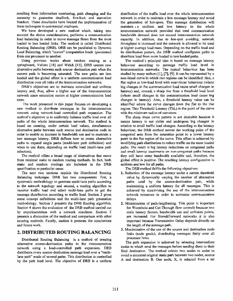
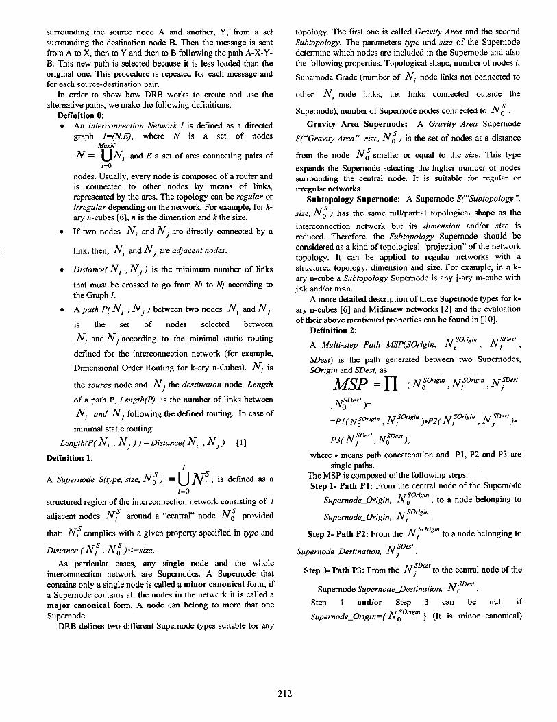
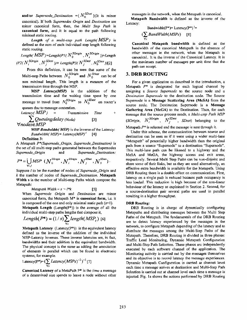
Fig. 2(a) shows the latency results for the hot-spot traffic pattern for two tori of 16 and 64 nodes. Figures 3 - 8 (a) show the latency results for the bit-reversal, butterfly, perfect shuffle and matrix transpose traffic patterns, for 16, 64 and 256 node 2D-Tori [Figs. 3(a), 4(a), 5(a)] and 4D, 6D and 8D Hypercubes [Figs. 6(a), 7(a), 8(a)], respectively. The results are very similar for all patterns, so we will comment them together.
In general, DRR routing performs better than static routing. The difference between the static routing and DRH routing curves for each pattern increases as the network traffic load grows. The Static Routing curves show a greater rise in latency as the load is increased than for DRH Routing. DRB routing makes an automatic configuration of the Metapath depending on the traffic load.
It can be seen that at low load rates (load < 0.4), DRE3 behaves nearly equal to static routing, This means that the DRE3 method does not charge the network when it is not necessary. At intermediate load rates (load between 0.4 - 0.7) DRB begins to use two multi-step paths, reducing latency. At higher load rates (load > 0.7) it uses the maximum number of MSPs allowed, resulting in higher latency reductions. While load is increasing, latency improvements are increasing too, resulting in latency reductions bigger than 50% at the highest load.
At the same time, as these latency improvements are
achieved, the throughput is increased as can be seen in Fig. 2 (b) for the hot-spot traffic pattern, in Figs. 3-8(b) for the bit- reversal, butterfly, perfect shuffle and matrix transpose traffic patterns for 16, 64 and 256 node 2D-Tori [Figs. 3(b), 4(b), S(b)] and 4D, 6D and 8D Hypercubes [Figs. 6(b), 7(b), 8(b)], respectively. The throughput is improved up to 50% for DRB routing while static routing performs worse since it gets saturated earlier.
It can be seen that DRB shows good scaleability because the same behaviour was observed from sizes 16 to 256 nodes.
Rnxl(tpnToRusW~ . ..a.. ‘.., . . ._ -. ‘._, . : m . : . . : . : : . Fig. 2 Performance results for the hot-spot pattern
0.9 -
i 0.8 -
s
1 0.7 -
i P 0.6 .
2 To5 Inaan*~B*~~J
Y w.m-r.z.‘D... ' * a a I L B E
0.2 0.4 0.6 o.tl 1 0.4' 0.05 0.2 0.4 0.6 c N-Appledtood PJmmwedwLmd
Fig. 3. Performance results for 4x4 torus
216
0.9
zo.7
4
I
0.6
_ 0.5
0.2
0.1
Fig. 4. Performance results forSx8 torus
-i
1
0.9
OL ’ 1 h ’ n ’ 0.05 0.2 0.4 0.6 0.8 I 0.4
Nolmallzed Applied Lxd
Fig. 7. Performance results for 6D Hypercube L&no/ HVPERClJBE8D
r+amdlze4iAppuedti Namaked ,.@kd Load
Fig. 8. Performance results for 8D Hypercube
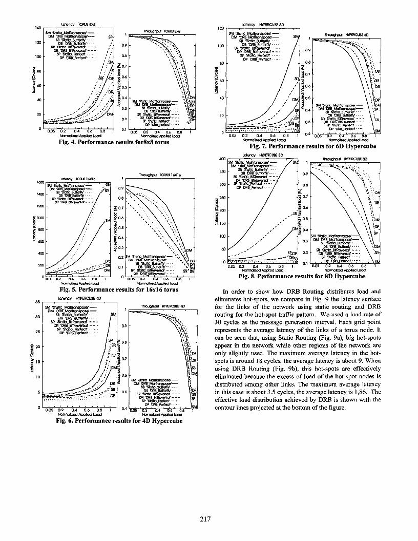
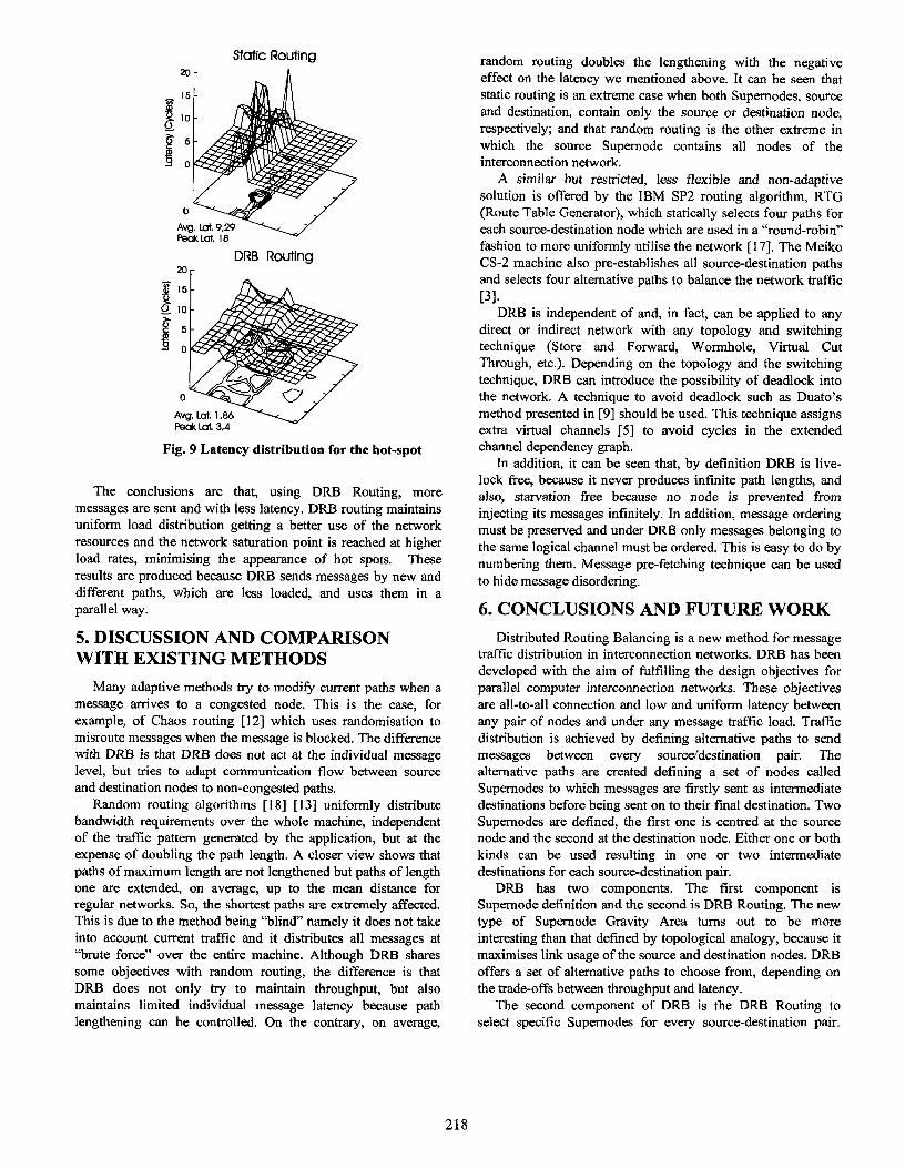
In order to show how DRB Routing distributes load and eliminates hot-spots, we compare in Fig. 9 the latency surface for the links of the network using static routing and DRE3 routing for the hot-spot traffic pattern. We used a load rate of 30 cycles as the message generation interval. Each grid point represents the average latency of the links of a torus node. It can be seen that, using Static Routing (Fig. 9a), big hot-spots appear in the network while other regions of the network are only slightly used. The maximum average latency in the hot- spots is around 18 cycles, the average latency is about 9. When using DRE3 Routing (Fig. 9b), this hot-spots are effectively eliminated because the excess of load of the hot-spot nodes is distributed among other links. The maximum average latency in this case is about 3.5 cycles, the average latency is 1,86. The effective load dishibution achieved by DRB is shown with the contour lines projected at the bottom of the figure.
Fig. 6. Performance results for 4D Hypercube
217
Slotic Routing
2O r DRB Routing
Fig. 9 Latency distribution for the hot-spot
The conclusions are that, using DRB Routing, more messages are sent and with less latency. DRB routing maintains uniform load distribution getting a better use of the network resources and the network saturation point is reached at higher load rates, minimising the appearance of hot spots. These results are produced because DRB sends messages by new and different paths, which are less loaded, and uses them in a parallel way.
5. DISCUSSION AND COMPARISON WITH EXISTING METHODS
Many adaptive methods try to modify current paths when a message arrives to a congested node. This is the case, for example, of Chaos routing [ 121 which uses randomisation to misroute messages when the message is blocked. The difference with DRB is that DRB does not act at the individual message level, but tries to adapt communication flow between source and destination nodes to non-congested paths.
Random routing algorithms [18] [13] uniformly distribute bandwidth requirements over the whole machine, independent of the traffic pattern generated by the application, but at the expense of doubling the path length. A closer view shows that paths of maximum length are not lengthened but paths of length one are extended, on average, up to the mean distance for regular networks. So, the shortest paths are extremely affected. This is due to the method being “blind” namely it does not take into account current traffic and it distributes all messages at “brute force” over the entire machine. Although DRB shares some objectives with random routing, the difference is that DRB does not only try to maintain throughput, but also maintains limited individual message latency because path lengthening can be controlled. On the contrary, on average,
random routing doubles the lengthening with the negative effect on the latency we mentioned above. It can be seen that static routing is an extreme case when both Supernodes, source and destination, contain only the source or destination node, respectively; and that random routing is the other extreme in which the source Supemode contains all nodes of the interconnection network.
A similar but restricted, less flexible and non-adaptive solution is offered by the IBM SP2 routing algorithm, RTG (Route Table Generator), which statically selects four paths for each source-destination node which are used in a “round-robin” fashion to more uniformly utilise the network [ 171. The Meiko CS-2 machine also pre-establishes all sourcedestination paths and selects four alternative paths to balance the network traffic [31.
DRB is independent of and, in fact, can be applied to any direct or indirect network with any topology and switching technique (Store and Forward, Wormhole, Virtual Cut Through, etc.). Depending on the topology and the switching technique, DRB can introduce the possibility of deadlock into the network. A technique to avoid deadlock such as Duato’s method presented in [9] should be used. This technique assigns extra virtual channels [5] to avoid cycles in the extended channel dependency graph.
In addition, it can be seen that, by definition DRB is live- lock free, because it never produces infinite path lengths, and also, starvation free because no node is prevented from injecting its messages infinitely. In addition, message ordering must be preserved and under DRB only messages belonging to the same logical channel must be ordered. This is easy to do by numbering them. Message pre-fetching technique can be used to hide message disordering.
6. CONCLUSIONS AND FUTURE WORK
Distributed Routing Balancing is a new method for message traffic distribution in interconnection networks. DRB has been developed with the aim of firlfilling the design objectives for parallel computer interconnection networks. These objectives are all-to-all connection and low and uniform latency between any pair of nodes and under any message traffic load. Traffic distribution is achieved by defining alternative paths to send messages between every source/destination pair. The alternative paths are created defining a set of nodes called Supemodes to which messages are firstly sent as intermediate destinations before being sent on to their final destination. Two Supernodes are defined, the first one is centred at the source node and the second at the destination node. Either one or both kinds can be used resulting in one or two intermediate destinations for each source-destination pair.
DRB has two components. The first component is Supernode definition and the second is DRB Routing. The new type of Supernode Gravity Area turns out to be more interesting than that defined by topological analogy, because it maximises link usage of the source and destination nodes. DRB offers a set of alternative paths to choose from, depending on the trade-offs between throughput and latency.
The second component of DRB is the DRB Routing to select specific Supemodes for every source-destination pair.
218
The presented dynamic DRB routing monitors traffic load and dynamically configures Supernode parameters depending on the current requirements of message load in the network. The method does not waste significant computation or communication resources because it is fully distributed, and the monitoring and decision overhead are linearly dependent on the number of messages in the network.
The evaluation made to validate DRB has revealed very good improvements in latency, effectively eliminating hot spots from the network. DRB is usehI for persistent communication patterns, which are the ones that can produce the worst hot-spot situations.
Latency is reduced by up to 50% and throughput is increased by up to 50%, too. Overheads are minimum because at low loads performance is not reduced.
Currently, we are testing the DR3 approach against other adaptive algorithms like Duato’s protocol Pm971, and the foreseeable results are very encouraging because DRB provides full adaptability with very low overhead. The overhead is minimum because decisions are made before the message is sent and the router design is not complicated. In addition, throughput is effectively increased due to the fact that several messages can be simultaneously sent in parallel through several MSPs of the Metapath.
7. ACKNOWLEDGEMENTS This work has been supported by the Spanish Comisi6n Interministerial de Ciencia y Tecnologia (CICYT) ,contract number TIC 98/0433
8. REFERENCES [l] Agarwal A. “Limits on Interconnection Network Performance”.
IEEE Transactions on Parallel and Distributed Systems, Vol. 2, N. 4, Ott 1991, pp.398-412.
[2] R. Beivide. E. Henada. J.L. Balc& y A. Armabarrena. “Optimal Distance Networks of Low Degree for Parallel Computers”. IEEE Trans. on Computers. Vol. 40. N. 10. pp. 1109-I 124.Oct 1992.
[3] Bokhari S. “Multiphase Complete Exchange on Paragon, SP2 and CS2”. IEEE Parallel and Distributed Technology, Vo1.4, N.3, Fall 1996, pp. 45-49.
141 Chien AA, Kim JH, “Planar Adaptive Routing: Low-Cost Adaptive Networks for Multiprocessors”. Proc. of the 19th Symposium
on Computer Architecture. May 1992, pp. 268-277 IS] Dally WJ. Seitz CL. “Deadlock-Free Message Routing in
Multiprocessor Interconnection Networks” IEEE Trans. On Computers. Vol. C-36. N. 5, May 1987, pp 547-553.
[6] Dally WJ. “Performance analysis of k-ary n-cube interconnection networks”. IEEE Trans. On Comput. Vol. 39. Jun. 1990, pp.775-785.
[7] Dally WJ. “Virtuai-Channel Flow Control”. IEEE Transactions on Parallel and Distributed Systems, Vol. 3, N. 2, Mar 1992, pp.194- 205.
[8] Duato J. “A new theory of Dead-lock free adaptive routing in wormhole networks” IEEE Transactions on Parallel and Distributed Systems, 4(12), Dee 1993, pp.I320-1331
[9] Duato J, Yalamanchili S, Ni L. “Interconnection Networks, an Engineering Approach”. IEEE Computer Society Press. 1997.
[IO] Garces I, Franc0 D, Luque E. “Improving Parallel Computer Communication: Dynamic Routing Balancing”. Proceedings of the Sixth Euromicro Workshop on Parallel and Distributed Processing. (IEEE-Euromicro) PDP98. Madrid. Spain. January 21-23, 1998. pp. 111-119
[l l] KIM 3, Liu Z, Chien A. “Compressionless Routing: A Framework for Adaptive and Fault-Tolerant Routing”. Proc. of the 21st Intl. Symposium oncomputer Architecture, Apr 1994, pp.289- 300
[12] Konstanyinidou S, Snyder L. “Chaos Router: Architecure and Performance”. Proc. of the 18th International Symposium on Computer Architecture, May 1991, pp.212-221
[13] May MD, Thompson PW, PH Welch Eds. “Networks, Routers and Transputers: Function, Performance and application”. 10s Press 1993
[ 141 Ni L, Glass C. “The Turn model for Adaptive Routing”. Proc. of the 19th International Symposium on Computer Architecture, IEEE Computer Society, May 1992, pp. 278-287
[IS] Pfister GF. Norton A. “Hot-Spot Contention and Combining in Multistage Interconnection Networks”. IEEE Trans. On Computers. Vol. 34. N.10 Ott 1985, pp. 943-948
[ 161 Pifarre GD, Gravano L, Felperin SA, Sanz JLC “Fully adaptive Minimal Deadlock Free Packet Routing in Hypercubes, Meshes and Other Networks: Algorithms and Simulations” IEEE Transactions on Parallel and Distributed Systems, Vol. 5, N.3, Mar 1994, pp. 247-263.
[17] Snir M, Hochschild P, Frye DD, Gildea KJ “The communication software and parallel environment of the IBM SP2”. IBM Systems Journal. Vo1.34, N.2, pp. 205-221.
[18] Valiant LG. Brebner GJ. “Universal Schemes for Parallel Communication”. ACM STOC. Milwaukee 198 1. pp. 263-277
219