Embed Size (px)
Citation preview
A
Da
b
a
ARAA
KSKF
1
Aoudmgttoctp
ora
tptpe
dT
0d
Wear 266 (2009) 560–565
Contents lists available at ScienceDirect
Wear
journa l homepage: www.e lsev ier .com/ locate /wear
new look at surface metrology
avid Whitehousea,b,∗
School of Engineering, University of Warwick, Taylor Hobson, Leicester, UKCentre for Precision Technologies, University of Huddersfield, 171 Cromwell Lane, Burton Green, Coventry CV4 8AN, UK
r t i c l e i n f o
rticle history:
a b s t r a c t
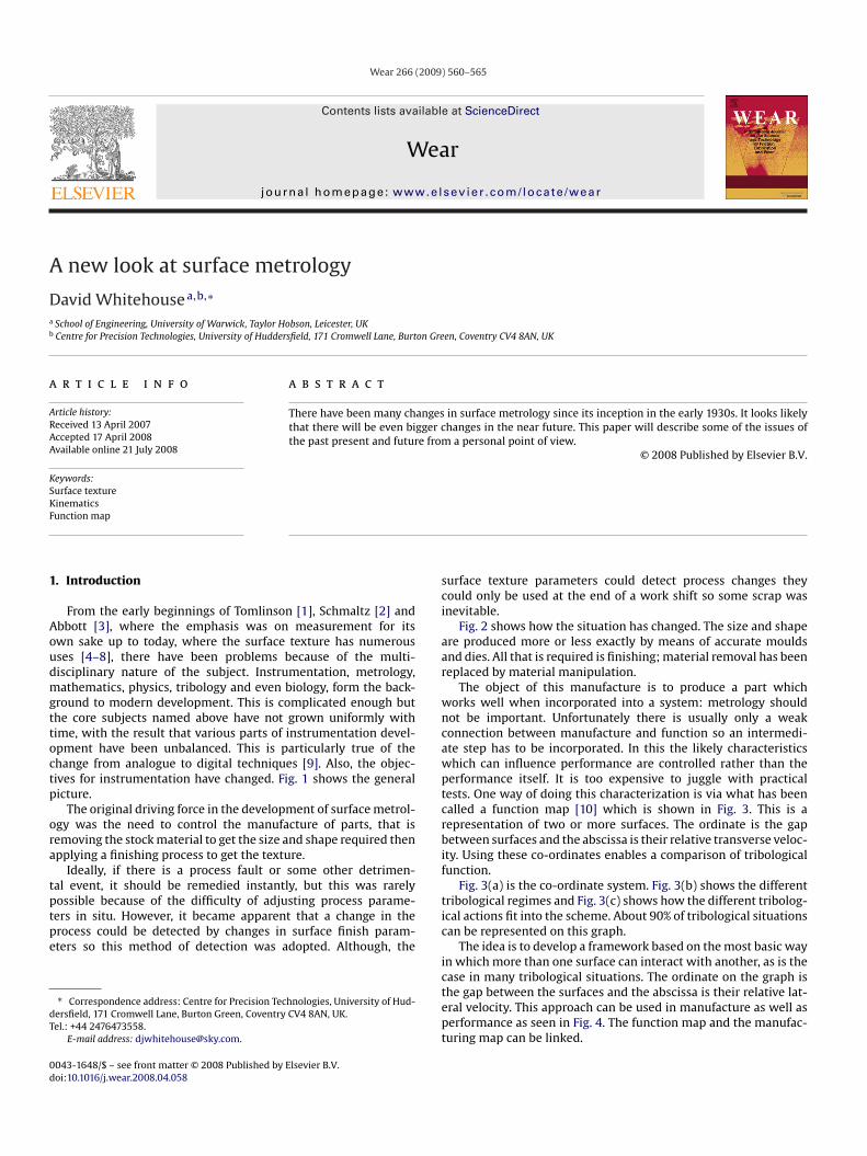
There have been many changes in surface metrology since its inception in the early 1930s. It looks likely
eceived 13 April 2007ccepted 17 April 2008vailable online 21 July 2008eywords:urface textureinematics
that there will be even bigger changes in the near future. This paper will describe some of the issues ofthe past present and future from a personal point of view.
© 2008 Published by Elsevier B.V.
sci
aar
wncawptcrbif
unction map
. Introduction
From the early beginnings of Tomlinson [1], Schmaltz [2] andbbott [3], where the emphasis was on measurement for itswn sake up to today, where the surface texture has numerousses [4–8], there have been problems because of the multi-isciplinary nature of the subject. Instrumentation, metrology,athematics, physics, tribology and even biology, form the back-
round to modern development. This is complicated enough buthe core subjects named above have not grown uniformly withime, with the result that various parts of instrumentation devel-pment have been unbalanced. This is particularly true of thehange from analogue to digital techniques [9]. Also, the objec-ives for instrumentation have changed. Fig. 1 shows the generalicture.
The original driving force in the development of surface metrol-gy was the need to control the manufacture of parts, that isemoving the stock material to get the size and shape required thenpplying a finishing process to get the texture.
Ideally, if there is a process fault or some other detrimen-al event, it should be remedied instantly, but this was rarely
ossible because of the difficulty of adjusting process parame-ers in situ. However, it became apparent that a change in therocess could be detected by changes in surface finish param-ters so this method of detection was adopted. Although, the∗ Correspondence address: Centre for Precision Technologies, University of Hud-ersfield, 171 Cromwell Lane, Burton Green, Coventry CV4 8AN, UK.el.: +44 2476473558.
E-mail address: [email protected].
tic
ictept
043-1648/$ – see front matter © 2008 Published by Elsevier B.V.oi:10.1016/j.wear.2008.04.058
urface texture parameters could detect process changes theyould only be used at the end of a work shift so some scrap wasnevitable.
Fig. 2 shows how the situation has changed. The size and shapere produced more or less exactly by means of accurate mouldsnd dies. All that is required is finishing; material removal has beeneplaced by material manipulation.
The object of this manufacture is to produce a part whichorks well when incorporated into a system: metrology shouldot be important. Unfortunately there is usually only a weakonnection between manufacture and function so an intermedi-te step has to be incorporated. In this the likely characteristicshich can influence performance are controlled rather than theerformance itself. It is too expensive to juggle with practicalests. One way of doing this characterization is via what has beenalled a function map [10] which is shown in Fig. 3. This is aepresentation of two or more surfaces. The ordinate is the gapetween surfaces and the abscissa is their relative transverse veloc-
ty. Using these co-ordinates enables a comparison of tribologicalunction.
Fig. 3(a) is the co-ordinate system. Fig. 3(b) shows the differentribological regimes and Fig. 3(c) shows how the different tribolog-cal actions fit into the scheme. About 90% of tribological situationsan be represented on this graph.
The idea is to develop a framework based on the most basic wayn which more than one surface can interact with another, as is the
ase in many tribological situations. The ordinate on the graph ishe gap between the surfaces and the abscissa is their relative lat-ral velocity. This approach can be used in manufacture as well aserformance as seen in Fig. 4. The function map and the manufac-uring map can be linked.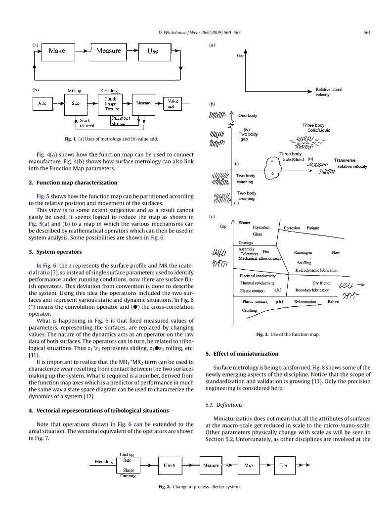
D. Whitehouse / Wear 266 (2009) 560–565 561
mi
2
t
eFbs
3
rpitf(o
pvdl[
cmttd
4
ai
5
nse
5
Fig. 1. (a) Uses of metrology and (b) value add.
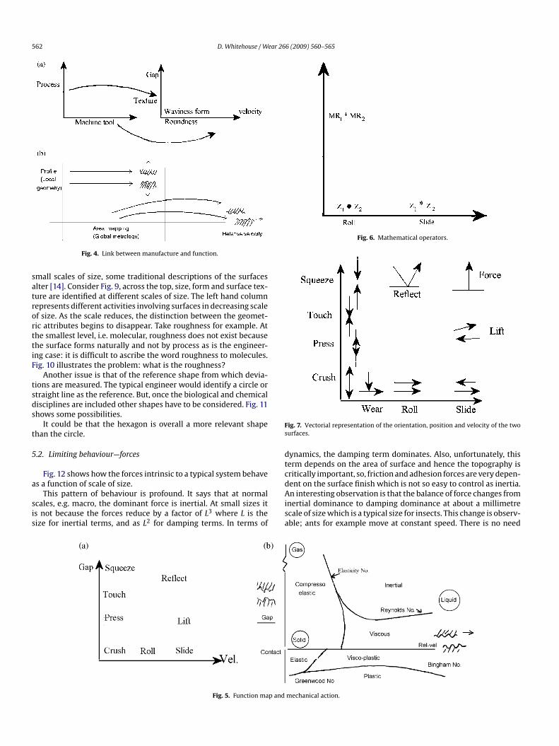
Fig. 4(a) shows how the function map can be used to connectanufacture. Fig. 4(b) shows how surface metrology can also link
nto the Function Map parameters.
. Function map characterization
Fig. 5 shows how the function map can be partitioned accordingo the relative position and movement of the surfaces.
This view is to some extent subjective and as a result cannotasily be used. It seems logical to reduce the map as shown inig. 5(a) and (b) to a map in which the various mechanisms cane described by mathematical operators which can then be used inystem analysis. Some possibilities are shown in Fig. 6.
. System operators
In Fig. 6, the z represents the surface profile and MR the mate-ial ratio [7], so instead of single surface parameters used to identifyerformance under running conditions, now there are surface fin-
sh operators. This deviation from convention is done to describehe system. Using this idea the operations included the two sur-aces and represent various static and dynamic situations. In Fig. 6*) means the convolution operator and (�) the cross-correlationperator.
What is happening in Fig. 6 is that fixed measured values ofarameters, representing the surfaces, are replaced by changingalues. The nature of the dynamics acts as an operator on the rawata of both surfaces. The operators can in turn, be related to tribo-
ogical situations. Thus z1*z2 represents sliding, z1�z2 rolling, etc.11].
It is important to realize that the MR1*MR2 term can be used toharacterize wear resulting from contact between the two surfacesaking up the system. What is required is a number, derived from
he function map axes which is a predictor of performance in muchhe same way a state space diagram can be used to characterize theynamics of a system [12].
. Vectorial representations of tribological situations
Note that operations shown in Fig. 6 can be extended to thereal situation. The vectorial equivalent of the operators are shownn Fig. 7.
aOS
Fig. 2. Change in proces
Fig. 3. Use of the function map.
. Effect of miniaturization
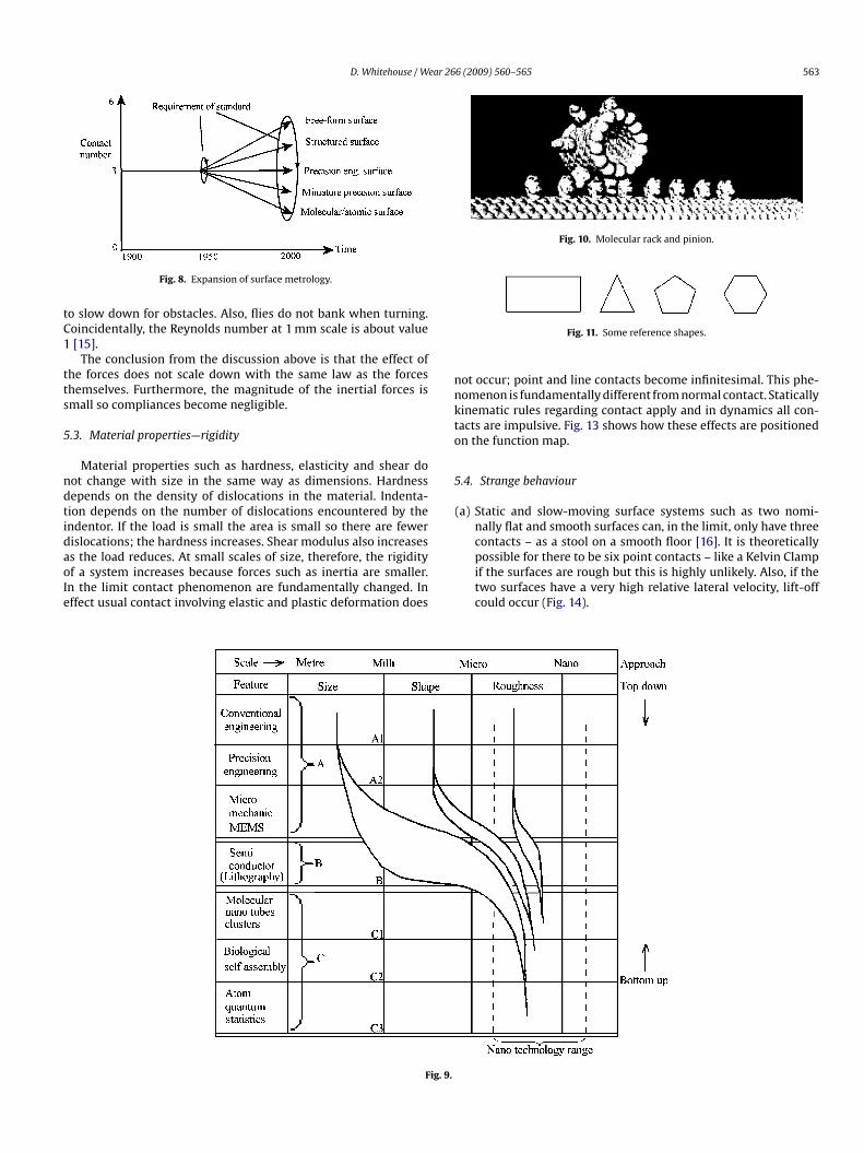
Surface metrology is being transformed. Fig. 8 shows some of theewly emerging aspects of the discipline. Notice that the scope oftandardization and validation is growing [13]. Only the precisionngineering is considered here.
.1. Definitions
Miniaturization does not mean that all the attributes of surfacest the macro-scale get reduced in scale to the micro-/nano-scale.ther parameters physically change with scale as will be seen inection 5.2. Unfortunately, as other disciplines are involved at the
s—Better system.
562 D. Whitehouse / Wear 266 (2009) 560–565
satrorttiF
tsds
t
5
a
sis
Fig. 6. Mathematical operators.
Fs
dtc
Fig. 4. Link between manufacture and function.
mall scales of size, some traditional descriptions of the surfaceslter [14]. Consider Fig. 9, across the top, size, form and surface tex-ure are identified at different scales of size. The left hand columnepresents different activities involving surfaces in decreasing scalef size. As the scale reduces, the distinction between the geomet-ic attributes begins to disappear. Take roughness for example. Athe smallest level, i.e. molecular, roughness does not exist becausehe surface forms naturally and not by process as is the engineer-ng case: it is difficult to ascribe the word roughness to molecules.ig. 10 illustrates the problem: what is the roughness?
Another issue is that of the reference shape from which devia-ions are measured. The typical engineer would identify a circle ortraight line as the reference. But, once the biological and chemicalisciplines are included other shapes have to be considered. Fig. 11hows some possibilities.
It could be that the hexagon is overall a more relevant shapehan the circle.
.2. Limiting behaviour—forces
Fig. 12 shows how the forces intrinsic to a typical system behave
s a function of scale of size.This pattern of behaviour is profound. It says that at normalcales, e.g. macro, the dominant force is inertial. At small sizes its not because the forces reduce by a factor of L3 where L is theize for inertial terms, and as L2 for damping terms. In terms of
dAisa
Fig. 5. Function map and
ig. 7. Vectorial representation of the orientation, position and velocity of the twourfaces.
ynamics, the damping term dominates. Also, unfortunately, thiserm depends on the area of surface and hence the topography isritically important, so, friction and adhesion forces are very depen-
ent on the surface finish which is not so easy to control as inertia.n interesting observation is that the balance of force changes fromnertial dominance to damping dominance at about a millimetrecale of size which is a typical size for insects. This change is observ-ble; ants for example move at constant speed. There is no need
mechanical action.
D. Whitehouse / Wear 266 (2009) 560–565 563
tC1
tts
5
ndtidaoIe
Fig. 10. Molecular rack and pinion.
nnkto
5
Fig. 8. Expansion of surface metrology.
o slow down for obstacles. Also, flies do not bank when turning.oincidentally, the Reynolds number at 1 mm scale is about value[15].
The conclusion from the discussion above is that the effect ofhe forces does not scale down with the same law as the forceshemselves. Furthermore, the magnitude of the inertial forces ismall so compliances become negligible.
.3. Material properties—rigidity
Material properties such as hardness, elasticity and shear doot change with size in the same way as dimensions. Hardnessepends on the density of dislocations in the material. Indenta-ion depends on the number of dislocations encountered by thendentor. If the load is small the area is small so there are fewer
islocations; the hardness increases. Shear modulus also increasess the load reduces. At small scales of size, therefore, the rigidityf a system increases because forces such as inertia are smaller.n the limit contact phenomenon are fundamentally changed. Inffect usual contact involving elastic and plastic deformation doesFig. 9.
Fig. 11. Some reference shapes.
ot occur; point and line contacts become infinitesimal. This phe-omenon is fundamentally different from normal contact. Staticallyinematic rules regarding contact apply and in dynamics all con-acts are impulsive. Fig. 13 shows how these effects are positionedn the function map.
.4. Strange behaviour
(a) Static and slow-moving surface systems such as two nomi-nally flat and smooth surfaces can, in the limit, only have threecontacts – as a stool on a smooth floor [16]. It is theoretically
possible for there to be six point contacts – like a Kelvin Clampif the surfaces are rough but this is highly unlikely. Also, if thetwo surfaces have a very high relative lateral velocity, lift-offcould occur (Fig. 14).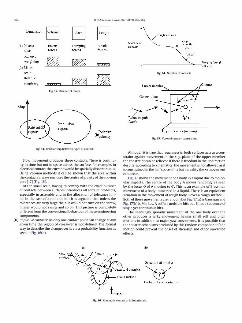
564 D. Whitehouse / Wear 266 (2009) 560–565
Fig. 12. Balance of forces.
(
Fig. 14. Number of contacts.
stdic
ubmsBFs
o
Fig. 13. Relationship between types of contact.
Slow movement produces three contacts. There is continu-ity in time but not in space across the surface, for example, inelectrical contact the current would be spatially discontinuous.Using Voronoi methods it can be shown that the area withinthe contacts always encloses the centre of gravity of the movingpart [17] (Fig. 15).
At the small scale, having to comply with the exact numberof contacts between surfaces introduces all sorts of problems,especially in assembly and in the allocation of tolerance lim-its. In the case of a nut and bolt it is arguable that unless thetolerances are very large the nut would not turn on the screw,hinges would not swing and so on. This picture is completelydifferent from the conventional behaviour of these engineeringcomponents.
b) Impulsive contacts: As only one contact point can change at anygiven time the region of crossover is not defined. The formalway to describe the changeover is via a probability function asseen in Fig. 16(b).
mtme
Fig. 16. Kinematic contac
Fig. 15. Voronoi centre—constraints.
Although it is true that roughness in both surfaces acts as a con-traint against movement in the x, y, plane of the upper memberhe constraint can be relieved if there is freedom in the +z directionespite, according to kinematics, the movement is not allowed as it
s constrained in the half space of −z but in reality the +z movementan occur.
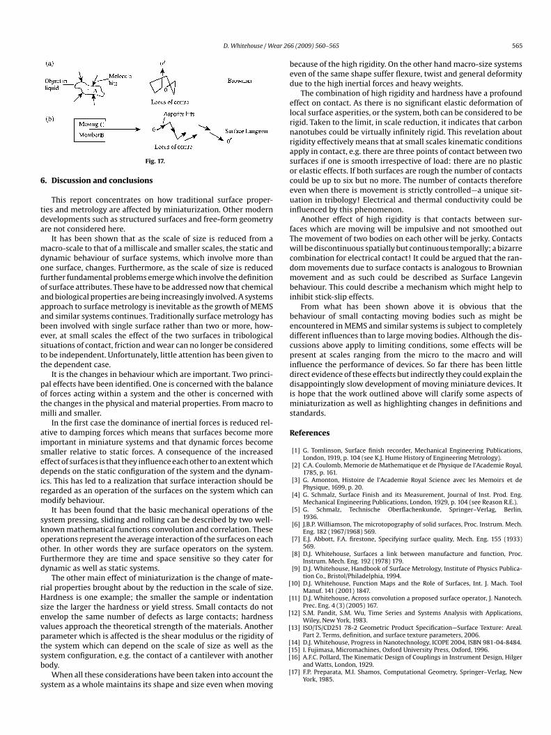
Fig. 17 shows the movement of a body in a liquid due to molec-lar impacts. The centre of the body A moves randomly as seeny the locus O of A moving to 0′. This is an example of Brownianovement of a body immersed in a liquid. There is an equivalent
ituation in the movement of rough body B over a rough surface C.oth of these movements are random but Fig. 17(a) is Gaussian andig. 17(b) is Markov. A suffers multiple hits but B has a sequence ofingle yet continuous hits.
The seemingly sporadic movement of the one body over thether produces a jerky movement having small roll and pitchotions in addition to major yaw movements. It is possible that
he shear mechanisms produced by this random component of theotion could prevent the onset of stick-slip and other unwanted
ffects.
t at infinitesimals.
D. Whitehouse / Wear 26
6
tda
mdofoaaabestt
potm
aisedirm
skooFd
rHsevptsb
s
bed
elrnrasoceui
fTwcdmbi
bedcpiddims
R
[
[
[
[
[14] D.J. Whitehouse, Progress in Nanotechnology, ICOPE 2004, ISBN 981-04-8484.
Fig. 17.
. Discussion and conclusions
This report concentrates on how traditional surface proper-ies and metrology are affected by miniaturization. Other modernevelopments such as structured surfaces and free-form geometryre not considered here.
It has been shown that as the scale of size is reduced from aacro-scale to that of a milliscale and smaller scales, the static and
ynamic behaviour of surface systems, which involve more thanne surface, changes. Furthermore, as the scale of size is reducedurther fundamental problems emerge which involve the definitionf surface attributes. These have to be addressed now that chemicalnd biological properties are being increasingly involved. A systemspproach to surface metrology is inevitable as the growth of MEMSnd similar systems continues. Traditionally surface metrology haseen involved with single surface rather than two or more, how-ver, at small scales the effect of the two surfaces in tribologicalituations of contact, friction and wear can no longer be consideredo be independent. Unfortunately, little attention has been given tohe dependent case.
It is the changes in behaviour which are important. Two princi-al effects have been identified. One is concerned with the balancef forces acting within a system and the other is concerned withhe changes in the physical and material properties. From macro to
illi and smaller.In the first case the dominance of inertial forces is reduced rel-
tive to damping forces which means that surfaces become moremportant in miniature systems and that dynamic forces becomemaller relative to static forces. A consequence of the increasedffect of surfaces is that they influence each other to an extent whichepends on the static configuration of the system and the dynam-
cs. This has led to a realization that surface interaction should beegarded as an operation of the surfaces on the system which canodify behaviour.It has been found that the basic mechanical operations of the
ystem pressing, sliding and rolling can be described by two well-nown mathematical functions convolution and correlation. Theseperations represent the average interaction of the surfaces on eachther. In other words they are surface operators on the system.urthermore they are time and space sensitive so they cater forynamic as well as static systems.
The other main effect of miniaturization is the change of mate-ial properties brought about by the reduction in the scale of size.ardness is one example; the smaller the sample or indentation
ize the larger the hardness or yield stress. Small contacts do notnvelop the same number of defects as large contacts; hardnessalues approach the theoretical strength of the materials. Anotherarameter which is affected is the shear modulus or the rigidity of
he system which can depend on the scale of size as well as theystem configuration, e.g. the contact of a cantilever with anotherody.When all these considerations have been taken into account theystem as a whole maintains its shape and size even when moving
[[
[
6 (2009) 560–565 565
ecause of the high rigidity. On the other hand macro-size systemsven of the same shape suffer flexure, twist and general deformityue to the high inertial forces and heavy weights.
The combination of high rigidity and hardness have a profoundffect on contact. As there is no significant elastic deformation ofocal surface asperities, or the system, both can be considered to beigid. Taken to the limit, in scale reduction, it indicates that carbonanotubes could be virtually infinitely rigid. This revelation aboutigidity effectively means that at small scales kinematic conditionspply in contact, e.g. there are three points of contact between twourfaces if one is smooth irrespective of load: there are no plasticr elastic effects. If both surfaces are rough the number of contactsould be up to six but no more. The number of contacts thereforeven when there is movement is strictly controlled—a unique sit-ation in tribology! Electrical and thermal conductivity could be
nfluenced by this phenomenon.Another effect of high rigidity is that contacts between sur-
aces which are moving will be impulsive and not smoothed outhe movement of two bodies on each other will be jerky. Contactsill be discontinuous spatially but continuous temporally; a bizarre
ombination for electrical contact! It could be argued that the ran-om movements due to surface contacts is analogous to Brownianovement and as such could be described as Surface Langevin
ehaviour. This could describe a mechanism which might help tonhibit stick-slip effects.
From what has been shown above it is obvious that theehaviour of small contacting moving bodies such as might bencountered in MEMS and similar systems is subject to completelyifferent influences than to large moving bodies. Although the dis-ussions above apply to limiting conditions, some effects will beresent at scales ranging from the micro to the macro and will
nfluence the performance of devices. So far there has been littleirect evidence of these effects but indirectly they could explain theisappointingly slow development of moving miniature devices. It
s hope that the work outlined above will clarify some aspects ofiniaturization as well as highlighting changes in definitions and
tandards.
eferences
[1] G. Tomlinson, Surface finish recorder, Mechanical Engineering Publications,London, 1919, p. 104 (see K.J. Hume History of Engineering Metrology).
[2] C.A. Coulomb, Memorie de Mathematique et de Physique de l’Academie Royal,1785, p. 161.
[3] G. Amonton, Histoire de l’Academie Royal Science avec les Memoirs et dePhysique, 1699, p. 20.
[4] G. Schmalz, Surface Finish and its Measurement, Journal of Inst. Prod. Eng.Mechanical Engineering Publications, London, 1929, p. 104 (see Reason R.E.).
[5] G. Schmalz, Technische Oberflachenkunde, Springer–Verlag, Berlin,1936.
[6] J.B.P. Williamson, The microtopography of solid surfaces, Proc. Instrum. Mech.Eng. 182 (1967/1968) 569.
[7] E.J. Abbott, F.A. firestone, Specifying surface quality, Mech. Eng. 155 (1933)569.
[8] D.J. Whitehouse, Surfaces a link between manufacture and function, Proc.Instrum. Mech. Eng. 192 (1978) 179.
[9] D.J. Whitehouse, Handbook of Surface Metrology, Institute of Physics Publica-tion Co., Bristol/Philadelphia, 1994.
10] D.J. Whitehouse, Function Maps and the Role of Surfaces, Int. J. Mach. ToolManuf. 141 (2001) 1847.
11] D.J. Whitehouse, Across convolution a proposed surface operator, J. Nanotech.Prec. Eng. 4 (3) (2005) 167.
12] S.M. Pandit, S.M. Wu, Time Series and Systems Analysis with Applications,Wiley, New York, 1983.
13] ISO/TS/CD251 78-2 Geometric Product Specification—Surface Texture: Areal.Part 2. Terms, definition, and surface texture parameters, 2006.
15] I. Fujimasa, Micromachines, Oxford University Press, Oxford, 1996.16] A.F.C. Pollard, The Kinematic Design of Couplings in Instrument Design, Hilger
and Watts, London, 1929.17] F.P. Preparata, M.I. Shamos, Computational Geometry, Springer–Verlag, New
York, 1985.