Embed Size (px)
Citation preview
A new hybrid method for the analysis of surrounded
antennas mounted on large platforms
Benoıt Le Lepvrier, Renaud Loison, Raphael Gillard, Philippe Pouliguen,
Patrick Potier, Laurent Patier
To cite this version:
Benoıt Le Lepvrier, Renaud Loison, Raphael Gillard, Philippe Pouliguen, Patrick Potier, etal.. A new hybrid method for the analysis of surrounded antennas mounted on large platforms.IEEE Transactions on Antennas and Propagation, Institute of Electrical and Electronics Engi-neers, 2014, 62 (5), pp.1-10. <10.1109/TAP.2014.2307333>. <hal-00986979>
HAL Id: hal-00986979
https://hal.archives-ouvertes.fr/hal-00986979
Submitted on 5 May 2014
HAL is a multi-disciplinary open accessarchive for the deposit and dissemination of sci-entific research documents, whether they are pub-lished or not. The documents may come fromteaching and research institutions in France orabroad, or from public or private research centers.
L’archive ouverte pluridisciplinaire HAL, estdestinee au depot et a la diffusion de documentsscientifiques de niveau recherche, publies ou non,emanant des etablissements d’enseignement et derecherche francais ou etrangers, des laboratoirespublics ou prives.
IEEE TRANSACTION ON ANTENNAS AND PROPAGATION 1
A new hybrid method for the analysis of
surrounded antennas mounted on large platformsBenoit Le Lepvrier, Renaud Loison, Raphael Gillard, Member, IEEE, Philippe Pouliguen, Patrick Potier,
and Laurent Patier
Abstract—An efficient technique to provide fast and accurateanalysis of wide-band surrounded antennas mounted on elec-trically large platforms is presented and validated in this paper.The hybrid method combines Dual-Grid FDTD (DG-FDTD) withIterative Physical Optics (IPO) to analyze on-platform antennaradiation. In section IV of this paper, DG-FDTD/IPO is appliedto the analysis of a wide-band antenna mounted on a vehicle.The ability to address the problem of antenna placement is alsodemonstrated.
Index Terms—hybrid methods, DG-FDTD, IPO, multi-scalemethod, antenna on structure.
I. INTRODUCTION
ANTENNA placement on platforms such as aircraft,
spacecraft or motor vehicles is becoming ever more
constrained. Therefore, antennas are frequently placed close to
complex elements on the structure. For this kind of problem,
the complex vicinity of the antenna and the platform may have
a significant effect on its behavior. So, it is of great interest to
develop appropriate methods to estimate the distortion of the
performance of the on-board antennas [1].
EM analysis of modern antenna-on-platform problems is
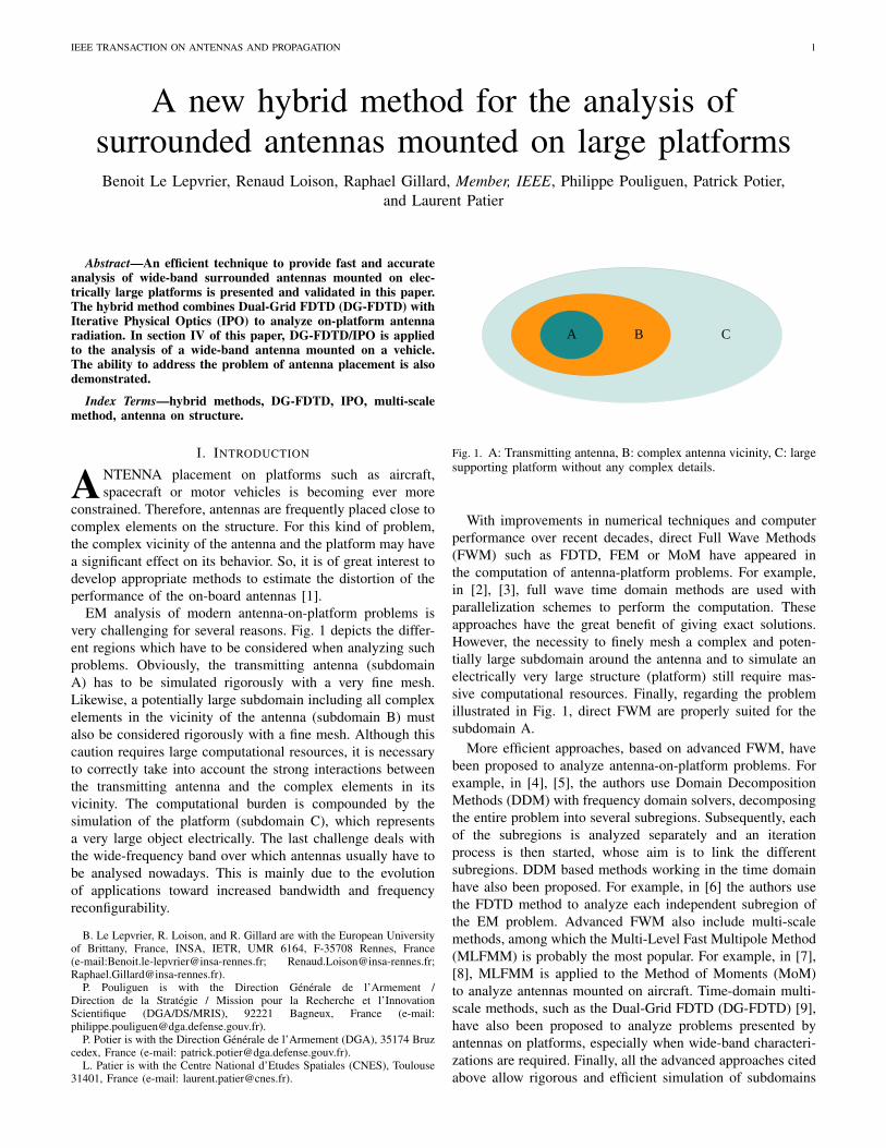
very challenging for several reasons. Fig. 1 depicts the differ-
ent regions which have to be considered when analyzing such
problems. Obviously, the transmitting antenna (subdomain
A) has to be simulated rigorously with a very fine mesh.
Likewise, a potentially large subdomain including all complex
elements in the vicinity of the antenna (subdomain B) must
also be considered rigorously with a fine mesh. Although this
caution requires large computational resources, it is necessary
to correctly take into account the strong interactions between
the transmitting antenna and the complex elements in its
vicinity. The computational burden is compounded by the
simulation of the platform (subdomain C), which represents
a very large object electrically. The last challenge deals with
the wide-frequency band over which antennas usually have to
be analysed nowadays. This is mainly due to the evolution
of applications toward increased bandwidth and frequency
reconfigurability.
B. Le Lepvrier, R. Loison, and R. Gillard are with the European Universityof Brittany, France, INSA, IETR, UMR 6164, F-35708 Rennes, France(e-mail:[email protected]; [email protected];[email protected]).
P. Pouliguen is with the Direction Generale de l’Armement /Direction de la Strategie / Mission pour la Recherche et l’InnovationScientifique (DGA/DS/MRIS), 92221 Bagneux, France (e-mail:[email protected]).
P. Potier is with the Direction Generale de l’Armement (DGA), 35174 Bruzcedex, France (e-mail: [email protected]).
L. Patier is with the Centre National d’Etudes Spatiales (CNES), Toulouse31401, France (e-mail: [email protected]).
A B C
Fig. 1. A: Transmitting antenna, B: complex antenna vicinity, C: largesupporting platform without any complex details.
With improvements in numerical techniques and computer
performance over recent decades, direct Full Wave Methods
(FWM) such as FDTD, FEM or MoM have appeared in
the computation of antenna-platform problems. For example,
in [2], [3], full wave time domain methods are used with
parallelization schemes to perform the computation. These
approaches have the great benefit of giving exact solutions.
However, the necessity to finely mesh a complex and poten-
tially large subdomain around the antenna and to simulate an
electrically very large structure (platform) still require mas-
sive computational resources. Finally, regarding the problem
illustrated in Fig. 1, direct FWM are properly suited for the
subdomain A.
More efficient approaches, based on advanced FWM, have
been proposed to analyze antenna-on-platform problems. For
example, in [4], [5], the authors use Domain Decomposition
Methods (DDM) with frequency domain solvers, decomposing
the entire problem into several subregions. Subsequently, each
of the subregions is analyzed separately and an iteration
process is then started, whose aim is to link the different
subregions. DDM based methods working in the time domain
have also been proposed. For example, in [6] the authors use
the FDTD method to analyze each independent subregion of
the EM problem. Advanced FWM also include multi-scale
methods, among which the Multi-Level Fast Multipole Method
(MLFMM) is probably the most popular. For example, in [7],
[8], MLFMM is applied to the Method of Moments (MoM)
to analyze antennas mounted on aircraft. Time-domain multi-
scale methods, such as the Dual-Grid FDTD (DG-FDTD) [9],
have also been proposed to analyze problems presented by
antennas on platforms, especially when wide-band characteri-
zations are required. Finally, all the advanced approaches cited
above allow rigorous and efficient simulation of subdomains
2 IEEE TRANSACTION ON ANTENNAS AND PROPAGATION
A and B. Although more efficient than direct FWM, advanced
FWM do not completely succeed in cutting the computational
burden, especially when very large platforms must be consid-
ered (such as domain C).
The most efficient way to deal with such large structures is
certainly to use Asymptotic Methods (AM) such as Physical-
Optics (PO) or Uniform Theory of Diffraction (UTD) [10],
[11]. However, regarding the problem illustrated in Fig. 1,
these methods are not properly suited for subdomains A and
B.
Hybrid method coupling a direct FWM with an AM has
frequently been written about in published material [12]–[22],
however, this hybridization scheme does not give a satisfactory
answer to our problem. Indeed, the complex antenna vicinity
is both too complex to be analyzed with AM and too large to
be computed efficiently with direct FWM.
As a consequence, a judicious solution consists of hy-
bridizing an advanced FWM with an AM. One example
of hybridization in the frequency domain is given in [23].
The authors use the FE-BI method, enhanced with domain
decomposition and fast algorithms, to efficiently compute large
antenna arrays. The platform is then analyzed with UTD or
Iterative Physical Optics (IPO). But full frequency domain
hybrid methods, such as the latter, are not appropriate for
wide-band characterizations: thus time-domain methods have
to be preferred. However, full time-domain hybrid methods
experience difficulties in handling electrically large structures.
In [20], a specific algorithm is proposed to improve efficiency
and reduce memory storage in computation, but it has only
been applied to small structures.
Hence, we propose here a new hybrid method combining a
time-domain AFWM, DG-FDTD [9], and a frequency-domain
AM, IPO [24]–[29]. DG-FDTD is a multi-scale time domain
method based on FDTD which enables efficient and rigorous
wide-band simulations of antennas and their complex vicinity
[30]. The hybridization with IPO allows the limitation on the
size of the structure to be overcome. In other words, the ap-
plication domain of the DG-FDTD is extended to the accurate
and efficient computation of surrounded antennas mounted on
electrically large structures thanks to its combination with the
IPO method. To our best knowledge it is the first time that
DG-FDTD has been hybridized with IPO.
This paper is organised as follows. DG-FDTD/IPO is pre-
sented in section II. Section III is dedicated to the validation of
the method. Examples of its application and associated numer-
ical results are presented in Section IV. Finally, conclusions
are drawn in the last section.
II. DG-FDTD/IPO FORMULATION
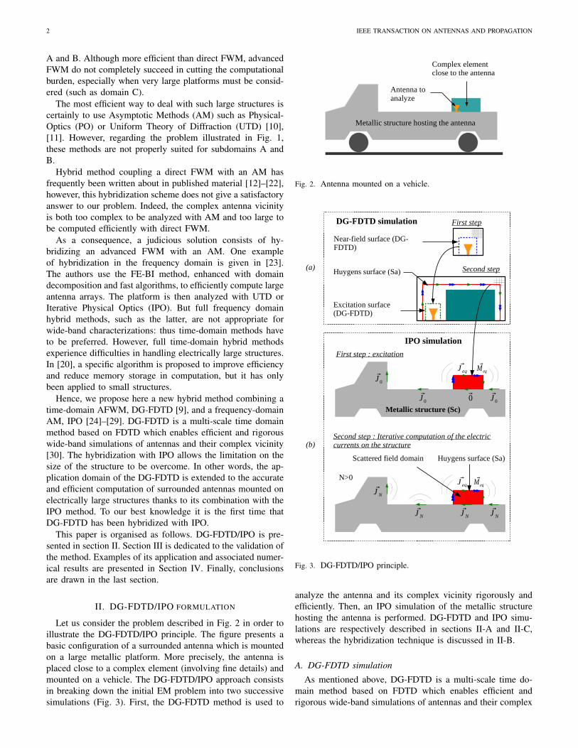
Let us consider the problem described in Fig. 2 in order to
illustrate the DG-FDTD/IPO principle. The figure presents a
basic configuration of a surrounded antenna which is mounted
on a large metallic platform. More precisely, the antenna is
placed close to a complex element (involving fine details) and
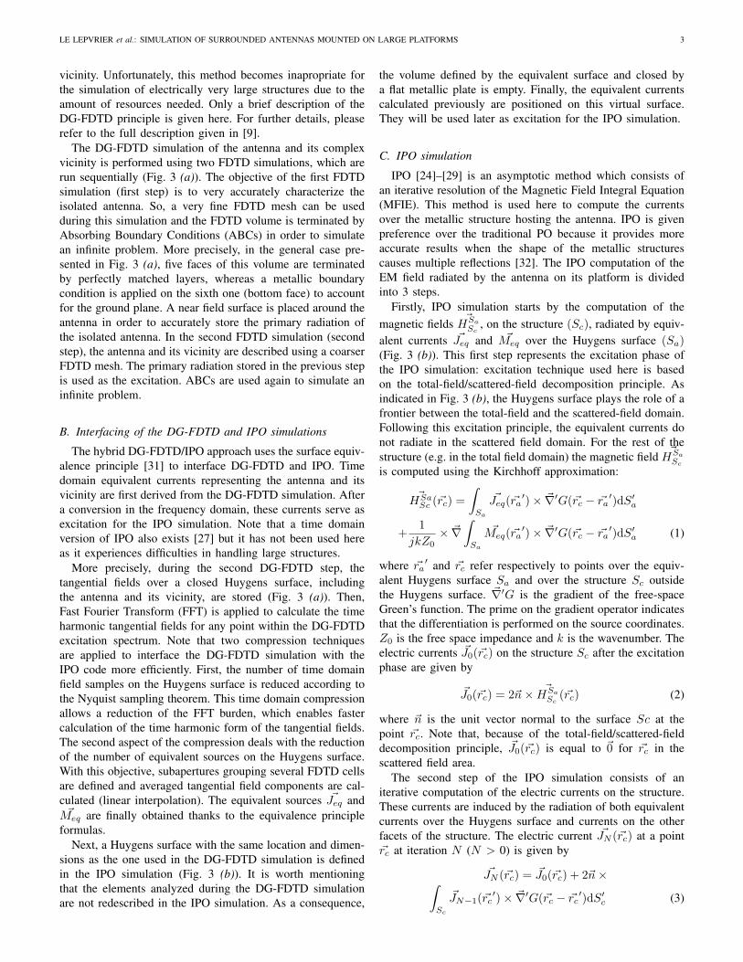
mounted on a vehicle. The DG-FDTD/IPO approach consists
in breaking down the initial EM problem into two successive
simulations (Fig. 3). First, the DG-FDTD method is used to
Antenna to analyze
Metallic structure hosting the antenna
Complex element close to the antenna
Fig. 2. Antenna mounted on a vehicle.
First step
Second step
J 0
DG-FDTD simulation
IPO simulation
Near-field surface (DG-FDTD)
Excitation surface (DG-FDTD)
First step : excitation
J 0
J 0
J eq M eq
J NJ N
J N
J N
Second step : Iterative computation of the electric currents on the structure
Metallic structure (Sc)
J eq M eq
Scattered field domain Huygens surface (Sa)
0
N>0
(b)
(a) Huygens surface (Sa)
Fig. 3. DG-FDTD/IPO principle.
analyze the antenna and its complex vicinity rigorously and
efficiently. Then, an IPO simulation of the metallic structure
hosting the antenna is performed. DG-FDTD and IPO simu-
lations are respectively described in sections II-A and II-C,
whereas the hybridization technique is discussed in II-B.
A. DG-FDTD simulation
As mentioned above, DG-FDTD is a multi-scale time do-
main method based on FDTD which enables efficient and
rigorous wide-band simulations of antennas and their complex
LE LEPVRIER et al.: SIMULATION OF SURROUNDED ANTENNAS MOUNTED ON LARGE PLATFORMS 3
vicinity. Unfortunately, this method becomes inapropriate for
the simulation of electrically very large structures due to the
amount of resources needed. Only a brief description of the
DG-FDTD principle is given here. For further details, please
refer to the full description given in [9].
The DG-FDTD simulation of the antenna and its complex
vicinity is performed using two FDTD simulations, which are
run sequentially (Fig. 3 (a)). The objective of the first FDTD
simulation (first step) is to very accurately characterize the
isolated antenna. So, a very fine FDTD mesh can be used
during this simulation and the FDTD volume is terminated by
Absorbing Boundary Conditions (ABCs) in order to simulate
an infinite problem. More precisely, in the general case pre-
sented in Fig. 3 (a), five faces of this volume are terminated
by perfectly matched layers, whereas a metallic boundary
condition is applied on the sixth one (bottom face) to account
for the ground plane. A near field surface is placed around the
antenna in order to accurately store the primary radiation of
the isolated antenna. In the second FDTD simulation (second
step), the antenna and its vicinity are described using a coarser
FDTD mesh. The primary radiation stored in the previous step
is used as the excitation. ABCs are used again to simulate an
infinite problem.
B. Interfacing of the DG-FDTD and IPO simulations
The hybrid DG-FDTD/IPO approach uses the surface equiv-
alence principle [31] to interface DG-FDTD and IPO. Time
domain equivalent currents representing the antenna and its
vicinity are first derived from the DG-FDTD simulation. After
a conversion in the frequency domain, these currents serve as
excitation for the IPO simulation. Note that a time domain
version of IPO also exists [27] but it has not been used here
as it experiences difficulties in handling large structures.
More precisely, during the second DG-FDTD step, the
tangential fields over a closed Huygens surface, including
the antenna and its vicinity, are stored (Fig. 3 (a)). Then,
Fast Fourier Transform (FFT) is applied to calculate the time
harmonic tangential fields for any point within the DG-FDTD
excitation spectrum. Note that two compression techniques
are applied to interface the DG-FDTD simulation with the
IPO code more efficiently. First, the number of time domain
field samples on the Huygens surface is reduced according to
the Nyquist sampling theorem. This time domain compression
allows a reduction of the FFT burden, which enables faster
calculation of the time harmonic form of the tangential fields.
The second aspect of the compression deals with the reduction
of the number of equivalent sources on the Huygens surface.
With this objective, subapertures grouping several FDTD cells
are defined and averaged tangential field components are cal-
culated (linear interpolation). The equivalent sources ~Jeq and~Meq are finally obtained thanks to the equivalence principle
formulas.
Next, a Huygens surface with the same location and dimen-
sions as the one used in the DG-FDTD simulation is defined
in the IPO simulation (Fig. 3 (b)). It is worth mentioning
that the elements analyzed during the DG-FDTD simulation
are not redescribed in the IPO simulation. As a consequence,
the volume defined by the equivalent surface and closed by
a flat metallic plate is empty. Finally, the equivalent currents
calculated previously are positioned on this virtual surface.
They will be used later as excitation for the IPO simulation.
C. IPO simulation
IPO [24]–[29] is an asymptotic method which consists of
an iterative resolution of the Magnetic Field Integral Equation
(MFIE). This method is used here to compute the currents
over the metallic structure hosting the antenna. IPO is given
preference over the traditional PO because it provides more
accurate results when the shape of the metallic structures
causes multiple reflections [32]. The IPO computation of the
EM field radiated by the antenna on its platform is divided
into 3 steps.
Firstly, IPO simulation starts by the computation of the
magnetic fields~HSa
Sc, on the structure (Sc), radiated by equiv-
alent currents ~Jeq and ~Meq over the Huygens surface (Sa)(Fig. 3 (b)). This first step represents the excitation phase of
the IPO simulation: excitation technique used here is based
on the total-field/scattered-field decomposition principle. As
indicated in Fig. 3 (b), the Huygens surface plays the role of a
frontier between the total-field and the scattered-field domain.
Following this excitation principle, the equivalent currents do
not radiate in the scattered field domain. For the rest of the
structure (e.g. in the total field domain) the magnetic field~HSa
Sc
is computed using the Kirchhoff approximation:
~HSaSc (~rc) =
∫Sa
~Jeq(~ra′)× ~∇′G(~rc − ~ra
′)dS′
a
+1
jkZ0
× ~∇
∫Sa
~Meq(~ra′)× ~∇′G(~rc − ~ra
′)dS′
a (1)
where ~ra′
and ~rc refer respectively to points over the equiv-
alent Huygens surface Sa and over the structure Sc outside
the Huygens surface. ~∇′G is the gradient of the free-space
Green’s function. The prime on the gradient operator indicates
that the differentiation is performed on the source coordinates.
Z0 is the free space impedance and k is the wavenumber. The
electric currents ~J0(~rc) on the structure Sc after the excitation
phase are given by
~J0(~rc) = 2~n× ~HSa
Sc(~rc) (2)
where ~n is the unit vector normal to the surface Sc at the
point ~rc. Note that, because of the total-field/scattered-field
decomposition principle, ~J0(~rc) is equal to ~0 for ~rc in the
scattered field area.
The second step of the IPO simulation consists of an
iterative computation of the electric currents on the structure.
These currents are induced by the radiation of both equivalent
currents over the Huygens surface and currents on the other
facets of the structure. The electric current ~JN (~rc) at a point
~rc at iteration N (N > 0) is given by
~JN (~rc) = ~J0(~rc) + 2~n×∫Sc
~JN−1(~rc′)× ~∇′G(~rc − ~rc
′)dS′
c (3)
4 IEEE TRANSACTION ON ANTENNAS AND PROPAGATION
Monopole antenna
l
h
θ
x
y
l
Nearby dielectric surrounding environment
Metallic structure
cdielec
d
cdielec
cdielec
εr
z
Fig. 4. Antenna mounted on a metallic structure. l = 3.9 m = 13λ1GHz , h = 1.15 m = 3.83 λ1GHz , d = 0.15 m = 0.5 λ1GHz , Cdielec
= 0.18 m = 0.6 λ1GHz , ǫr = 10.
where ~rc and ~rc′
are two points on the structure Sc. Note
that point ~rc can belong to the scattered field domain since N> 0. This iterative process is repeated until a stable value for
the electric currents is reached. It is worth noting that an IPO
simulation with 0 IPO iteration (N = 0) corresponds to the
traditional PO simulation. Consequently, ~J0(~rc) are equal to
the traditional PO currents.
The integrations presented in equations (1) and (3) are
performed taking into account shadowing effects. For instance,
in equation (1), if point ~rc is not visible from point ~ra′, the
contribution from point ~ra′
is set to zero.
The last step aims at computing the far field radiated at
observation point ~r by the equivalent currents, and the currents
on the structure. The Kirchhoff approximation is used again :
~H(~r) =
∫Sa
~Jeq(~ra′)× ~∇′G(~r − ~ra
′)dS′
a
+1
jkZ0
× ~∇
∫Sa
~Meq(~ra′)× ~∇′G(~r − ~ra
′)dS′
a
+
∫Sc
~JN (~rc′)× ~∇′G(~r − ~rc
′)dS′
c (4)
~E(~r) =1
jkY0
× ~∇
∫Sa
~Jeq(~ra′)× ~∇′G(~r − ~ra
′)dS′
a
+1
jkY0
× ~∇
∫Sc
~JN (~rc′)× ~∇′G(~r − ~rc
′)dS′
c
−
∫Sa
~Meq(~ra′)× ~∇′G(~r − ~ra
′)dS′
a (5)
where Y0 is equal to 1/Z0.
III. VALIDATION OF DG-FDTD/IPO
This section is dedicated to the validation of the DG-
FDTD/IPO approach presented in section II. To do so, the
radiation of a canonical antenna-on-structure is computed with
both DG-FDTD/IPO and advanced FWMs.
A. Description of the validation scenario
The EM problem (Fig. 4) includes a monopole antenna
surrounded by a dielectric element, mounted on an electrically
large metallic structure. The monopole antenna, whose central
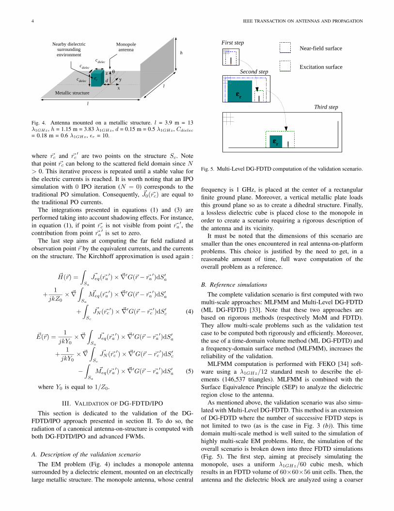
First step
Second step
εr
Near-field surface
Excitation surface
εr
Third step
Fig. 5. Multi-Level DG-FDTD computation of the validation scenario.
frequency is 1 GHz, is placed at the center of a rectangular
finite ground plane. Moreover, a vertical metallic plate loads
this ground plane so as to create a dihedral structure. Finally,
a lossless dielectric cube is placed close to the monopole in
order to create a scenario requiring a rigorous description of
the antenna and its vicinity.
It must be noted that the dimensions of this scenario are
smaller than the ones encountered in real antenna-on-platform
problems. This choice is justified by the need to get, in a
reasonable amount of time, full wave computation of the
overall problem as a reference.
B. Reference simulations
The complete validation scenario is first computed with two
multi-scale approaches: MLFMM and Multi-Level DG-FDTD
(ML DG-FDTD) [33]. Note that these two approaches are
based on rigorous methods (respectively MoM and FDTD).
They allow multi-scale problems such as the validation test
case to be computed both rigorously and efficiently. Moreover,
the use of a time-domain volume method (ML DG-FDTD) and
a frequency-domain surface method (MLFMM), increases the
reliability of the validation.
MLFMM computation is performed with FEKO [34] soft-
ware using a λ1GHz/12 standard mesh to describe the el-
ements (146,537 triangles). MLFMM is combined with the
Surface Equivalence Principle (SEP) to analyze the dielectric
region close to the antenna.
As mentioned above, the validation scenario was also simu-
lated with Multi-Level DG-FDTD. This method is an extension
of DG-FDTD where the number of successive FDTD steps is
not limited to two (as is the case in Fig. 3 (b)). This time
domain multi-scale method is well suited to the simulation of
highly multi-scale EM problems. Here, the simulation of the
overall scenario is broken down into three FDTD simulations
(Fig. 5). The first step, aiming at precisely simulating the
monopole, uses a uniform λ1GHz/60 cubic mesh, which
results in an FDTD volume of 60×60×56 unit cells. Then, the
antenna and the dielectric block are analyzed using a coarser
LE LEPVRIER et al.: SIMULATION OF SURROUNDED ANTENNAS MOUNTED ON LARGE PLATFORMS 5
DG-FDTD simulationFirst step
IPO simulation
Second step
εr
Near-field surface (DG-FDTD)
Excitation surface (DG-FDTD)
Huygens surface
Huygens surface
J eq M eq
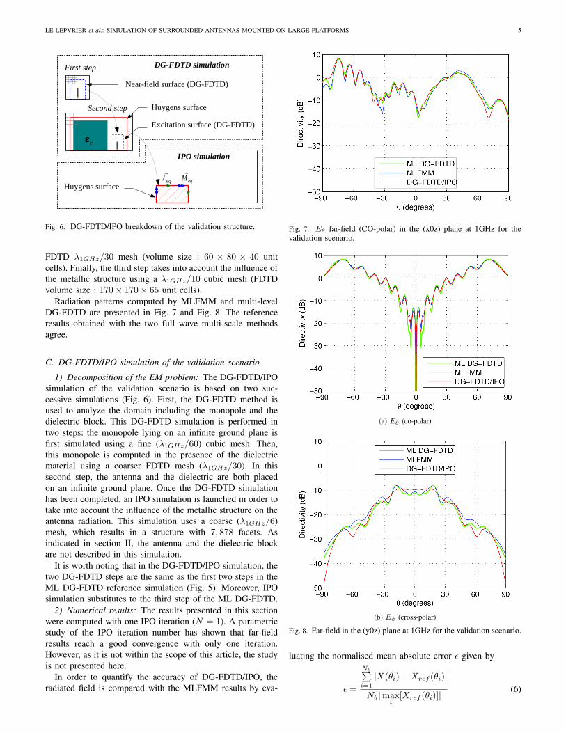
Fig. 6. DG-FDTD/IPO breakdown of the validation structure.
FDTD λ1GHz/30 mesh (volume size : 60 × 80 × 40 unit
cells). Finally, the third step takes into account the influence of
the metallic structure using a λ1GHz/10 cubic mesh (FDTD
volume size : 170× 170× 65 unit cells).
Radiation patterns computed by MLFMM and multi-level
DG-FDTD are presented in Fig. 7 and Fig. 8. The reference
results obtained with the two full wave multi-scale methods
agree.
C. DG-FDTD/IPO simulation of the validation scenario
1) Decomposition of the EM problem: The DG-FDTD/IPO
simulation of the validation scenario is based on two suc-
cessive simulations (Fig. 6). First, the DG-FDTD method is
used to analyze the domain including the monopole and the
dielectric block. This DG-FDTD simulation is performed in
two steps: the monopole lying on an infinite ground plane is
first simulated using a fine (λ1GHz/60) cubic mesh. Then,
this monopole is computed in the presence of the dielectric
material using a coarser FDTD mesh (λ1GHz/30). In this
second step, the antenna and the dielectric are both placed
on an infinite ground plane. Once the DG-FDTD simulation
has been completed, an IPO simulation is launched in order to
take into account the influence of the metallic structure on the
antenna radiation. This simulation uses a coarse (λ1GHz/6)
mesh, which results in a structure with 7, 878 facets. As
indicated in section II, the antenna and the dielectric block
are not described in this simulation.
It is worth noting that in the DG-FDTD/IPO simulation, the
two DG-FDTD steps are the same as the first two steps in the
ML DG-FDTD reference simulation (Fig. 5). Moreover, IPO
simulation substitutes to the third step of the ML DG-FDTD.
2) Numerical results: The results presented in this section
were computed with one IPO iteration (N = 1). A parametric
study of the IPO iteration number has shown that far-field
results reach a good convergence with only one iteration.
However, as it is not within the scope of this article, the study
is not presented here.
In order to quantify the accuracy of DG-FDTD/IPO, the
radiated field is compared with the MLFMM results by eva-
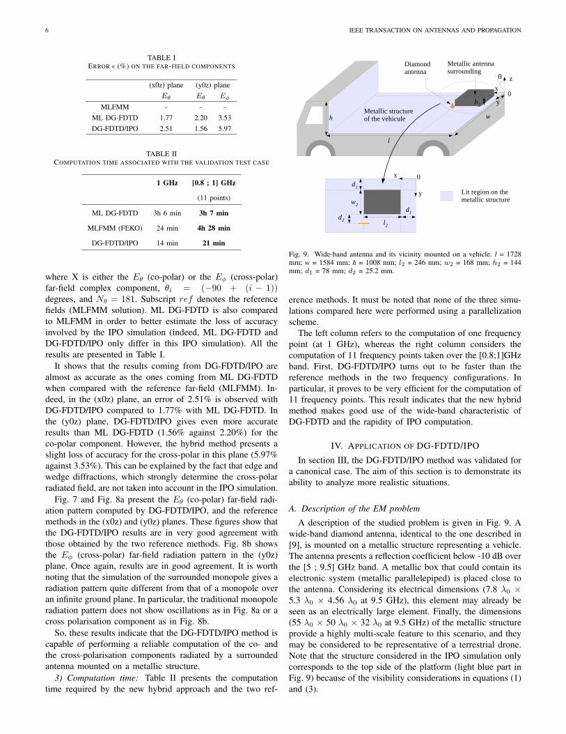
Fig. 7. Eθ far-field (CO-polar) in the (x0z) plane at 1GHz for thevalidation scenario.
(a) Eθ (co-polar)
(b) Eφ (cross-polar)
Fig. 8. Far-field in the (y0z) plane at 1GHz for the validation scenario.
luating the normalised mean absolute error ǫ given by
ǫ =
Nθ∑i=1
|X(θi)−Xref (θi)|
Nθ|maxi
[Xref (θi)]|(6)
6 IEEE TRANSACTION ON ANTENNAS AND PROPAGATION
TABLE IERROR ǫ (%) ON THE FAR-FIELD COMPONENTS
(x0z) plane (y0z) plane
Eθ Eθ Eφ
MLFMM - - -
ML DG-FDTD 1.77 2.20 3.53
DG-FDTD/IPO 2.51 1.56 5.97
TABLE IICOMPUTATION TIME ASSOCIATED WITH THE VALIDATION TEST CASE
1 GHz [0.8 ; 1] GHz
(11 points)
ML DG-FDTD 3h 6 min 3h 7 min
MLFMM (FEKO) 24 min 4h 28 min
DG-FDTD/IPO 14 min 21 min
where X is either the Eθ (co-polar) or the Eφ (cross-polar)
far-field complex component, θi = (−90 + (i − 1))degrees, and Nθ = 181. Subscript ref denotes the reference
fields (MLFMM solution). ML DG-FDTD is also compared
to MLFMM in order to better estimate the loss of accuracy
involved by the IPO simulation (indeed, ML DG-FDTD and
DG-FDTD/IPO only differ in this IPO simulation). All the
results are presented in Table I.
It shows that the results coming from DG-FDTD/IPO are
almost as accurate as the ones coming from ML DG-FDTD
when compared with the reference far-field (MLFMM). In-
deed, in the (x0z) plane, an error of 2.51% is observed with
DG-FDTD/IPO compared to 1.77% with ML DG-FDTD. In
the (y0z) plane, DG-FDTD/IPO gives even more accurate
results than ML DG-FDTD (1.56% against 2.20%) for the
co-polar component. However, the hybrid method presents a
slight loss of accuracy for the cross-polar in this plane (5.97%
against 3.53%). This can be explained by the fact that edge and
wedge diffractions, which strongly determine the cross-polar
radiated field, are not taken into account in the IPO simulation.
Fig. 7 and Fig. 8a present the Eθ (co-polar) far-field radi-
ation pattern computed by DG-FDTD/IPO, and the reference
methods in the (x0z) and (y0z) planes. These figures show that
the DG-FDTD/IPO results are in very good agreement with
those obtained by the two reference methods. Fig. 8b shows
the Eφ (cross-polar) far-field radiation pattern in the (y0z)
plane. Once again, results are in good agreement. It is worth
noting that the simulation of the surrounded monopole gives a
radiation pattern quite different from that of a monopole over
an infinite ground plane. In particular, the traditional monopole
radiation pattern does not show oscillations as in Fig. 8a or a
cross polarisation component as in Fig. 8b.
So, these results indicate that the DG-FDTD/IPO method is
capable of performing a reliable computation of the co- and
the cross-polarisation components radiated by a surrounded
antenna mounted on a metallic structure.
3) Computation time: Table II presents the computation
time required by the new hybrid approach and the two ref-
Diamond antenna
Metallic antenna surrounding
Metallic structure of the vehicule
z
y
y
x
l2
w2
w
l
h
0
h2
0d
1
h
d1
d2
Lit region on the metallic structure
x
θ
Fig. 9. Wide-band antenna and its vicinity mounted on a vehicle. l = 1728mm; w = 1584 mm; h = 1008 mm; l2 = 246 mm; w2 = 168 mm; h2 = 144mm; d1 = 78 mm; d2 = 25.2 mm.
erence methods. It must be noted that none of the three simu-
lations compared here were performed using a parallelization
scheme.
The left column refers to the computation of one frequency
point (at 1 GHz), whereas the right column considers the
computation of 11 frequency points taken over the [0.8;1]GHz
band. First, DG-FDTD/IPO turns out to be faster than the
reference methods in the two frequency configurations. In
particular, it proves to be very efficient for the computation of
11 frequency points. This result indicates that the new hybrid
method makes good use of the wide-band characteristic of
DG-FDTD and the rapidity of IPO computation.
IV. APPLICATION OF DG-FDTD/IPO
In section III, the DG-FDTD/IPO method was validated for
a canonical case. The aim of this section is to demonstrate its
ability to analyze more realistic situations.
A. Description of the EM problem
A description of the studied problem is given in Fig. 9. A
wide-band diamond antenna, identical to the one described in
[9], is mounted on a metallic structure representing a vehicle.
The antenna presents a reflection coefficient below -10 dB over
the [5 ; 9.5] GHz band. A metallic box that could contain its
electronic system (metallic parallelepiped) is placed close to
the antenna. Considering its electrical dimensions (7.8 λ0 ×5.3 λ0 × 4.56 λ0 at 9.5 GHz), this element may already be
seen as an electrically large element. Finally, the dimensions
(55 λ0 × 50 λ0 × 32 λ0 at 9.5 GHz) of the metallic structure
provide a highly multi-scale feature to this scenario, and they
may be considered to be representative of a terrestrial drone.
Note that the structure considered in the IPO simulation only
corresponds to the top side of the platform (light blue part in
Fig. 9) because of the visibility considerations in equations (1)
and (3).
LE LEPVRIER et al.: SIMULATION OF SURROUNDED ANTENNAS MOUNTED ON LARGE PLATFORMS 7
TABLE IIIERROR ǫ (%) ON THE FAR-FIELD
(x0z) plane (y0z) plane
Eθ Eφ Eθ Eφ
MLFMM - - - -
DG-FDTD/IPO 5.93 14.37 0.825 7.60
TABLE IVCOMPUTATION TIME ASSOCIATED WITH THE EXPLOITATION TEST CASE
radiation pattern wide-band computation
at 9.5 GHz (3.5 GHz bandwidth;
100 MHz step)
MLFMM (FEKO) 7h 55 min 11 days
3h 19 min 13h 44 min
DG-FDTD/IPO DG-FDTD: 2h 56 min DG-FDTD: 2h 56 min
IPO: 23 min IPO: 10h 48min
The DG-FDTD/IPO computation of this EM problem is
based on the breakdown proposed in Fig. 3 (section II).
Hence, The initial EM problem is split into two simulations.
First, DG-FDTD is used to simulate the diamond antenna,
taking into account the metallic element in the vicinity. In the
first step of DG-FDTD, the antenna is analyzed alone on an
infinite ground plane. This simulation uses a very fine FDTD
mesh (λ9.5GHz/105) so as to correctly model the triangular
geometry of the antenna and in so doing recover the measured
performances as presented in [9]. Then, an FDTD simulation
of the antenna with the metallic element in its vicinity is
performed. A coarser mesh (λ9.5GHz/26.25) is used during
this step to reduce the computational resources. Note that the
spatial discretization used in this second step of the DG-FDTD
must both be a multiple of the one used in the first step (×4),
and comply with the classic FDTD dispersion criteria. The
DG-FDTD simulation is followed by an IPO simulation of
the metallic structure hosting the antenna. The structure is
discretized with λ9.5GHz/4.4 square facets, about 19 facets
per square wavelength. This sampling density is in agreement
with the recommendation given in [24]. Finally, note that to
compute the structure only one iteration is used in the IPO
code.
B. Numerical results
The comparison of the radiation patterns computed with
DG-FDTD/IPO and FEKO at 9.5 GHz is first presented. Then,
the results of a wide-band computation are proposed.
1) comparison with FEKO at 9.5 GHz: Fig. 10 shows the
radiation patterns computed with DG-FDTD/IPO and FEKO
software at 9.5 GHz. To generate the FEKO results, the
overall structure is simulated with the MLFMM method. The
computation, on a 48 Gbit RAM workstation, requires an
appropriate parametrization of the FEKO simulation. First, an
SPAI (SParse Approximate Inverse) iterative preconditioner is
used to reduce the memory. Moreover, the overall structure is
discretized using a coarse mesh (λ9.5GHz/8) with the excep-
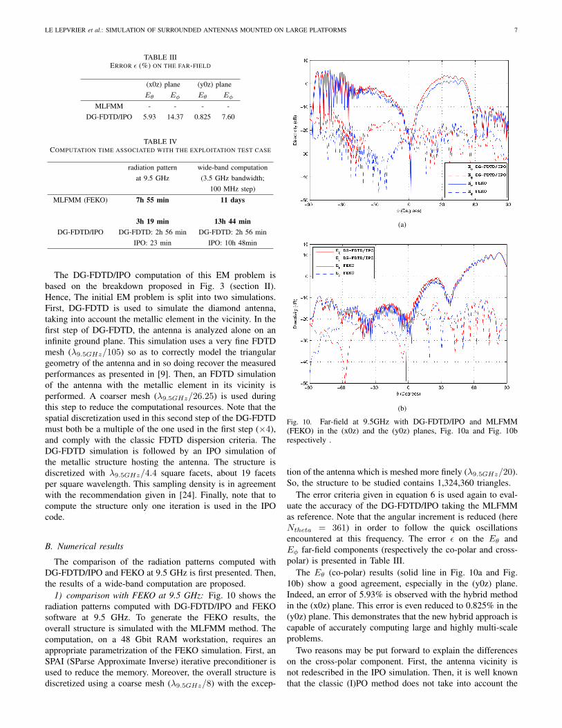
(a)
(b)
Fig. 10. Far-field at 9.5GHz with DG-FDTD/IPO and MLFMM(FEKO) in the (x0z) and the (y0z) planes, Fig. 10a and Fig. 10brespectively .
tion of the antenna which is meshed more finely (λ9.5GHz/20).
So, the structure to be studied contains 1,324,360 triangles.
The error criteria given in equation 6 is used again to eval-
uate the accuracy of the DG-FDTD/IPO taking the MLFMM
as reference. Note that the angular increment is reduced (here
Ntheta = 361) in order to follow the quick oscillations
encountered at this frequency. The error ǫ on the Eθ and
Eφ far-field components (respectively the co-polar and cross-
polar) is presented in Table III.
The Eθ (co-polar) results (solid line in Fig. 10a and Fig.
10b) show a good agreement, especially in the (y0z) plane.
Indeed, an error of 5.93% is observed with the hybrid method
in the (x0z) plane. This error is even reduced to 0.825% in the
(y0z) plane. This demonstrates that the new hybrid approach is
capable of accurately computing large and highly multi-scale
problems.
Two reasons may be put forward to explain the differences
on the cross-polar component. First, the antenna vicinity is
not redescribed in the IPO simulation. Then, it is well known
that the classic (I)PO method does not take into account the
8 IEEE TRANSACTION ON ANTENNAS AND PROPAGATION
Fig. 11. Computation of the electric far field for θ = + 45 degrees inthe (y0z) plane over the [6 ; 9.5] GHz band.
edge/wedge diffractions. But these diffractions may have a
significant effect on the cross-polar component.
Finally, as can be seen from Table IV, time-saving provided
by DG-FDTD/IPO is very significant for such realistic prob-
lems.
2) Wide-band computation: One of the benefits of the DG-
FDTD/IPO method is its wide-band characteristic. In order to
illustrate this aspect a wide-band computation was performed.
As an example, the electric far-field in the (y0z) plane for θ =
45 degrees over the [6 ; 9.5] GHz band is shown in Fig. 11.
Note that a 100 MHz step was used.
Table IV also presents the computation time associated with
the simulation of the far-field over the 3.5 GHz bandwidth with
DG-FDTD/IPO and MLFMM (FEKO). These results clearly
show the efficiency of DG-FDTD/IPO to compute wide-band
parameters. Indeed, the wider the analysis bandwith used,
the more attractive the DG-FDTD/IPO method becomes. As
indicated in section III-C3, the wide-band efficiency of the new
hybrid method is both linked to the wide-band characteristic
of the DG-FDTD and the low computational cost required by
the IPO simulation.
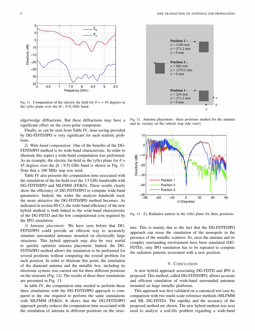
3) Antenna placement: We have seen before that DG-
FDTD/IPO could provide an efficient way to accurately
simulate surrounded antennas mounted on electrically large
structures. This hybrid approach may also be very useful
to quickly optimize antenna placement. Indeed, the DG-
FDTD/IPO method allows the simulation to be performed for
several positions without computing the overall problem for
each position. In order to illustrate this point, the simulation
of the diamond antenna and the metallic box, including its
electronic system, was carried out for three different positions
on the structure (Fig. 12). The results of these three simulations
are presented in Fig. 13.
In table IV, the computation time needed to perform those
three simulations with the DG-FDTD/IPO approach is com-
pared to the one required to perform the same simulations
with MLFMM (FEKO). It shows that the DG-FDTD/IPO
approach greatly reduces the computation time associated with
the simulation of antenna in different positions on the struc-
0
x
y
Position 2 :
x = 1548 mm
y = 271.2 mm
z = 0 mm
Position 1 :
x = 324 mmy = 271.2 mm
z = 0 mm
Position 3 :
x = 900 mm
y = 1279.2 mm
z = 0 mm
Fig. 12. Antenna placement : three positions studied for the antennaand its vicinity on the vehicle (top side view).
Fig. 13. Eθ Radiation pattern in the (x0z) plane for three positions.
ture. This is mainly due to the fact that the DG-FDTD/IPO
approach can reuse the simulation of the monopole in the
presence of the metallic scatterer. So, once the antenna and its
complex surrounding environment have been simulated (DG-
FDTD), only IPO simulation has to be repeated to compute
the radiation patterns associated with a new position.
V. CONCLUSION
A new hybrid approach associating DG-FDTD and IPO is
proposed. This method, called DG-FDTD/IPO, allows accurate
and efficient simulation of wide-band surrounded antennas
mounted on large metallic platforms.
This approach was first validated on a canonical test case by
comparison with two multi-scale reference methods (MLFMM
and ML DG-FDTD). The rapidity and the accuracy of the
proposed method are shown. The new hybrid method was next
used to analyze a real-life problem regarding a wide-band
LE LEPVRIER et al.: SIMULATION OF SURROUNDED ANTENNAS MOUNTED ON LARGE PLATFORMS 9
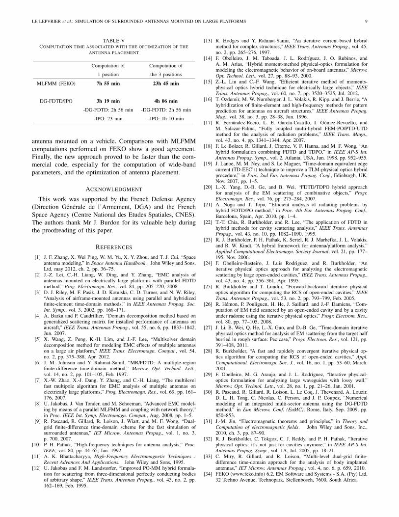
TABLE VCOMPUTATION TIME ASSOCIATED WITH THE OPTIMIZATION OF THE
ANTENNA PLACEMENT
Computation of Computation of
1 position the 3 positions
MLFMM (FEKO) 7h 55 min 23h 45 min
DG-FDTD/IPO 3h 19 min 4h 06 min
-DG-FDTD: 2h 56 min -DG-FDTD: 2h 56 min
-IPO: 23 min -IPO: 1h 10 min
antenna mounted on a vehicle. Comparisons with MLFMM
computations performed on FEKO show a good agreement.
Finally, the new approach proved to be faster than the com-
mercial code, especially for the computation of wide-band
parameters, and the optimization of antenna placement.
ACKNOWLEDGMENT
This work was supported by the French Defense Agency
(Direction Generale de l’Armement, DGA) and the French
Space Agency (Centre National des Etudes Spatiales, CNES).
The authors thank Mr J. Burdon for its valuable help during
the proofreading of this paper.
REFERENCES
[1] J. F. Zhang, X. Wei Ping, W. M. Yu, X. Y. Zhou, and T. J. Cui, “Spaceantenna modeling,” in Space Antenna Handbook. John Wiley and Sons,Ltd, may 2012, ch. 2, pp. 36–75.
[2] J.-Z. Lei, C.-H. Liang, W. Ding, and Y. Zhang, “EMC analysis ofantennas mounted on electrically large platforms with parallel FDTDmethod,” Prog. Electromagn. Res., vol. 84, pp. 205–220, 2008.
[3] D. J. Riley, M. F. Pasik, J. D. Kotulski, C. D. Turner, and N. W. Riley,“Analysis of airframe-mounted antennas using parallel and hybridizedfinite-element time-domain methods,” in IEEE Antennas Propag. Soc.
Int. Symp., vol. 3, 2002, pp. 168–171.[4] A. Barka and P. Caudrillier, “Domain decomposition method based on
generalized scattering matrix for installed performance of antennas onaircraft,” IEEE Trans. Antennas Propag., vol. 55, no. 6, pp. 1833–1842,Jun. 2007.
[5] X. Wang, Z. Peng, K.-H. Lim, and J.-F. Lee, “Multisolver domaindecomposition method for modeling EMC effects of multiple antennason a large air platform,” IEEE Trans. Electromagn. Compat., vol. 54,no. 2, pp. 375–388, Apr. 2012.
[6] J. M. Johnson and Y. Rahmat-Samil, “MR/FDTD: A multiple-regionfinite-difference–time-domain method,” Microw. Opt. Technol. Lett.,vol. 14, no. 2, pp. 101–105, Feb. 1997.
[7] X.-W. Zhao, X.-J. Dang, Y. Zhang, and C.-H. Liang, “The multilevelfast multipole algorithm for EMC analysis of multiple antennas onelectrically large platforms,” Prog. Electromagn. Res., vol. 69, pp. 161–176, 2007.
[8] U. Jakobus, J. Van Tonder, and M. Schoeman, “Advanced EMC model-ing by means of a parallel MLFMM and coupling with network theory,”in Proc. IEEE Int. Symp. Electromagn. Compat., Aug. 2008, pp. 1–5.
[9] R. Pascaud, R. Gillard, R. Loison, J. Wiart, and M. F. Wong, “Dual-grid finite-difference time-domain scheme for the fast simulation ofsurrounded antennas,” IET Microw. Antennas Propag., vol. 1, no. 3,p. 700, 2007.
[10] P. H. Pathak, “High-frequency techniques for antenna analysis,” Proc.
IEEE, vol. 80, pp. 44–65, Jan. 1992.[11] A. K. Bhattacharyya, High-Frequency Electromagnetic Techniques :
Recent Advances And Applications. John Wiley and Sons, 1995.[12] U. Jakobus and F. M. Landstorfer, “Improved PO-MM hybrid formula-
tion for scattering from three-dimensional perfectly conducting bodiesof arbitrary shape,” IEEE Trans. Antennas Propag., vol. 43, no. 2, pp.162–169, Feb. 1995.
[13] R. Hodges and Y. Rahmat-Samii, “An iterative current-based hybridmethod for complex structures,” IEEE Trans. Antennas Propag., vol. 45,no. 2, pp. 265–276, 1997.
[14] F. Obelleiro, J. M. Taboada, J. L. Rodrıguez, J. O. Rubinos, andA. M. Arias, “Hybrid moment-method physical-optics formulation formodeling the electromagnetic behavior of on-board antennas,” Microw.
Opt. Technol. Lett., vol. 27, pp. 88–93, 2000.[15] Z.-L. Liu and C.-F. Wang, “Efficient iterative method of moments-
physical optics hybrid technique for electrically large objects,” IEEE
Trans. Antennas Propag., vol. 60, no. 7, pp. 3520–3525, Jul. 2012.[16] T. Ozdemir, M. W. Nurnberger, J. L. Volakis, R. Kipp, and J. Berrie, “A
hybridization of finite-element and high-frequency methods for patternprediction for antennas on aircraft structures,” IEEE Antennas Propag.
Mag., vol. 38, no. 3, pp. 28–38, Jun. 1996.[17] R. Fernandez-Recio, L. E. Garcıa-Castillo, I. Gomez-Revuelto, and
M. Salazar-Palma, “Fully coupled multi-hybrid FEM-PO/PTD-UTDmethod for the analysis of radiation problems,” IEEE Trans. Magn.,vol. 43, no. 4, pp. 1341–1344, Apr. 2007.
[18] F. Le Bolzer, R. Gillard, J. Citerne, V. F. Hanna, and M. F. Wong, “Anhybrid formulation combining FDTD and TDPO,” in IEEE AP-S Int.
Antennas Propag. Symp., vol. 2, Atlanta, USA, Jun. 1998, pp. 952–955.[19] J. Lanoe, M. M. Ney, and S. Le Maguer, “Time-domain equivalent edge
current (TD-EEC’s) technique to improve a TLM-physical optics hybridprocedure,” in Proc. 2nd Eur. Antennas Propag. Conf., Edinburgh, UK,Nov. 2007, pp. 1–5.
[20] L.-X. Yang, D.-B. Ge, and B. Wei, “FDTD/TDPO hybrid approachfor analysis of the EM scattering of combinative objects,” Progr.
Electromagn. Res., vol. 76, pp. 275–284, 2007.[21] A. Noga and T. Topa, “Efficient analysis of radiating problems by
hybrid FDTD/PO method,” in Proc. 4th Eur. Antennas Propag. Conf.,Barcelona, Spain, Apr. 2010, pp. 1–4.
[22] T.-T. Chia, R. Burkholder, and R. Lee, “The application of FDTD inhybrid methods for cavity scattering analysis,” IEEE Trans. Antennas
Propag., vol. 43, no. 10, pp. 1082–1090, 1995.[23] R. J. Burkholder, P. H. Pathak, K. Sertel, R. J. Marhefka, J. L. Volakis,
and R. W. Kindt, “A hybrid framework for antenna/platform analysis,”Applied Computational Electromagn. Society Journal, vol. 21, pp. 177–195, Nov. 2006.
[24] F. Obelleiro-Basteiro, J. Luis Rodriguez, and R. Burkholder, “Aniterative physical optics approach for analyzing the electromagneticscattering by large open-ended cavities,” IEEE Trans. Antennas Propag.,vol. 43, no. 4, pp. 356–361, Apr. 1995.
[25] R. Burkholder and T. Lundin, “Forward-backward iterative physicaloptics algorithm for computing the RCS of open-ended cavities,” IEEE
Trans. Antennas Propag., vol. 53, no. 2, pp. 793–799, Feb. 2005.[26] R. Hemon, P. Pouliguen, H. He, J. Saillard, and J.-F. Damiens, “Com-
putation of EM field scattered by an open-ended cavity and by a cavityunder radome using the iterative physical optics,” Progr. Electrom. Res.,vol. 80, pp. 77–105, 2008.
[27] J. Li, B. Wei, Q. He, L.-X. Guo, and D.-B. Ge, “Time-domain iterativephysical optics method for analysis of EM scattering from the target halfburried in rough surface: Pec case,” Progr. Electrom. Res., vol. 121, pp.391–408, 2011.
[28] R. Burkholder, “A fast and rapidely convergent iterative physical op-tics algorithm for computing the RCS of open-ended cavities,” Appl.
Computational. Electromagn. Soc. J., vol. 16, no. 1, pp. 53–60, March.2001.
[29] F. Obelleiro, M. G. Araujo, and J. L. Rodrıguez, “Iterative physical-optics formulation for analyzing large waveguides with lossy wall,”Microw. Opt. Technol. Lett., vol. 28, no. 1, pp. 21–26, Jan. 2001.
[30] R. Pascaud, R. Gillard, R. Loison, L. Le Coq, J. Thevenard, A. Louzir,D. L. H. Tong, C. Nicolas, C. Person, and J. P. Coupez, “Numericalmodeling of an integrated multi-sector antenna using the DG-FDTDmethod,” in Eur. Microw. Conf. (EuMC), Rome, Italy, Sep. 2009, pp.850–853.
[31] J.-M. Jin, “Electromagnetic theorems and principles,” in Theory and
Computation of electromagnetic fields. John Wiley and Sons, Inc.,2010, ch. 3, pp. 87–90.
[32] R. J. Burkholder, C. Tokgoz, C. J. Reddy, and P. H. Pathak, “Iterativephysical optics: it’s not just for cavities anymore,” in IEEE AP-S Int.
Antennas Propag. Symp., vol. 1A, Jul. 2005, pp. 18–21.[33] C. Miry, R. Gillard, and R. Loison, “Multi-level dual-grid finite-
difference time-domain approach for the analysis of body implantedantennas,” IET Microw. Antennas Propag., vol. 4, no. 6, p. 659, 2010.
[34] FEKO (www.feko.info) 6.2, EM Software and Systems - S.A. (Pty) Ltd,32 Techno Avenue, Technopark, Stellenbosch, 7600, South Africa.
10 IEEE TRANSACTION ON ANTENNAS AND PROPAGATION
Benoit Le Lepvrier was born in Pabu, France, in1988. He received the Diplome d’Ingenieur (Masterlevel) degree in network and communication systemsfrom the National Institute of Applied Sciences(INSA), Rennes, France, in 2011. He is currentlyworking toward the Ph.D. degree in electronics atthe Electronics and Telecommunications Instituteof Rennes (IETR), France (in collaboration withthe Centre National d’Etudes Spatiales (CNES),Toulouse, France and the Direction Generale del’Armement (DGA) Bruz, France). His research in-
terests are computational electromagnetics for antennas on electrically largeand complex platforms.
Renaud Loison was born in Saint-Brieuc, France,on January 16, 1974. He received the Diplomed’Ingenieur and Ph.D. degrees from the National In-stitute of Applied Sciences (INSA), Rennes, France,in 1996 and 2000, respectively. In 2000, he joinedthe Institute of Electronics and Telecommunicationsof Rennes (IETR), Rennes, France, as an AssociateProfessor. Since 2009, he has been a Professor withthe Complex Radiating Systems Group, IETR. Hisresearch interests concern reflectarrays and numer-ical methods applied to the computer-aided design
(CAD) and optimization of microwave circuits and antennas.
Raphael Gillard received the Ph.D. degree in elec-tronics from the National Institute of Applied Sci-ences (INSA), Rennes, France, in 1992. He initiallyworked as a Research Engineer with the IPSIS Com-pany, Cesson-Sevigne, France, where he developeda commercial method of moments (MoM) code forthe simulation of microwave circuits and antennas.In 1993, he joined the National Institute of AppliedSciences (INSA), Rennes, France, as an AssistantProfessor. Since 2001, he has been a Full Professorwith the Antenna and Microwave Group, Electronics
and Telecommunications Institute of Rennes (IETR), Rennes, France, wherehe was in charge of electromagnetic (EM) modeling and optimization activity.Since 2006, he has been leading the Antenna and Microwave Group. Hehas coauthored 164 conference papers and 62 journal papers. His currentmain research interests are computational electromagnetics and reflectarrays.Prof. Gillard was a member of both the Executive and Governing Boardsof the European Antenna Centre of Excellence (ACE) from 2004 to 2008.He was co-leader of its antenna software activity (in charge of the softwarebenchmarking work package). He is member of several scientific committeesor review boards (EuCAP, EuMC, etc.).
Laurent Patier was born in Vichy, France, in 1984.He obtained his Master’s degree in Electromag-netic Compatibility and in Opto/Micro-Electronicsin 2007 at the University of Clermont-Ferrand(France). He received the Ph.D. degree in 2010 atONERA (Toulouse, France). In 2010, he joined theFrench Space Agency (CNES, Toulouse, France) asan engineer in antenna modelling. Since 2013, hehas been working in the EMC lab in the department“board electrical equipments” at CNES.
Philippe Pouliguen received the M.S. degree insignal processing and telecommunications, the Doc-toral degree in electronic and the “Habilitationa Diriger des Recherches” degree from the Uni-versity of Rennes 1, France, in 1986, 1990 and2000. In 1990, he joined the Direction Generalede l’Armement (DGA) at the Centre d’Electroniquede l’Armement (CELAR), now DGA InformationSuperiority (DGA/IS), in Bruz, France, where hewas a “DGA expert” in electromagnetic radiationand radar signatures analysis. He was also in charge
of the EMC (Expertise and ElectoMagnetism Computation) laboratory ofCELAR. Since December 2009, he has been the head of “acoustic andradio-electric waves” scientific domain at the office for advanced researchand innovation of the strategy directorate, DGA, Bagneux, France. Hisresearch interests include electromagnetic scattering and diffraction, RadarCross Section (RCS) measurement and modeling, asymptotic high frequencymethods, radar signal processing and analysis, antenna scattering problemsand Electronic Band Gap Materials. In these fields, he has published morethan 30 articles in refereed journals and more than 100 conference papers.