Embed Size (px)
Citation preview

A new device for stress monitoring in continuously welded railsusing bi-directional strain method
Ganzhong Liu1 • Hao Liu1 • Anqi Wei1 • Jieling Xiao1 • Ping Wang1 •
Shaozheng Li1
Received: 31 August 2017 / Revised: 22 March 2018 / Accepted: 14 May 2018 / Published online: 27 June 2018
� The Author(s) 2018
Abstract The technology of continuously welded rails
(CWRs) is important in modern railway track structures.
To measure rail stress, resistance strain gauges are pre-
ferred due to their good stability, sensitivity, and resistance
to external interference. Based on the bi-directional strain
method, we present a new method for measuring longitu-
dinal rail stress using resistance strain gauges and develop
a monitoring device for rail stress to realize long-term and
multi-point measurement. Also relevant experimental ver-
ification and analysis are conducted. Results indicate that
under various constraints the rail stress–strain values can
be calculated just with the measured total longitudinal
strain and total vertical strain. Considering the measure-
ment error caused by sectional feature of sensors, we put
forward a correction equation applicable to different stress
conditions. Although the temperature values of the four
full-bridge stress gauges can offset each other, the mea-
surement error caused by rail flexural strain can also be
eliminated to a certain extent at the same time, the non-
uniform distribution of rail cross section temperature and
unbalanced flexural strain still affect the measurement
error. The experimental results also show that the devel-
oped rail-stress-monitoring sensor is suitable for measuring
rail stress with reliable working performance.
Keywords Resistance strain gauge � Continuously welded
rail � Longitudinal force in rail � Bi-directional strainmethod � Monitoring instrument
1 Introduction
Continuously welded rails (CWRs) are an important tech-
nology in modern railway track structures. Nowadays, most
new railways worldwide belong to super long continuously
welded rail tracks. In addition, along with the rapid
development of high-speed railways in recent years, new
technologies in track structure have been widely used for
ballastless tracks, large-sized welded turnouts, CWRs on
long-span bridges, etc. As there is an additional longitu-
dinal rail force caused by track-bridge interaction, it poses
important challenges to preventing the expansion and
breaking of CWRs, especially track buckling and breakage
on long-span bridges which severely threat the track
structures of high-speed railways based on ballastless
tracks [1–3]. In high-temperature seasons, an excessively
high longitudinal tension in rail bars may cause track
buckling, lifting, rail-pad shifting, part damage and mal-
function, etc. In low-temperature seasons, rail bars under
an excessively high longitudinal tension are likely to cause
track breakage. The accurate measurement of longitudinal
rail stress and rail temperature is the key to scientific
evaluation, management and maintenance of CWRs [4, 5].
On the basis of physical principles that rail materials
have different mechanical, acoustical, electromagnetic, and
material properties under different stresses, many
researchers have tried to measure the longitudinal force in
rail bars using the methods such as the strain method,
flexural method, Barkhausen noise analysis (BNA) method,
X-ray method, magnetic permeability method, and
& Jieling Xiao
1 MOE Key Laboratory of High-speed Railway Engineering,
School of Civil Engineering, Southwest Jiaotong University,
No. 111 of the North Second Ring Road, Chengdu 610031,
China
123
J. Mod. Transport. (2018) 26(3):179–188
https://doi.org/10.1007/s40534-018-0164-z

ultrasonic method [6–11]. In 1992, Herzog developed a
longitudinal stress measurement (LSM) process and put
forward a patented method for measuring the fastening-
down temperature of rails. In the field of rail thermal and
residual stress measurements, there are a number of
important techniques have been developed over the years,
including rail uplifting or VERSE [12], neutron diffraction
[13], magneto-elastic methods or MAPS [14], Rayleigh
wave polarization measurements [15], nonlinear ultrasonic
measurements [16], and the hole drilling method [17].
However, subject to limitations such as diversified rail-
section sizes, weather, temperature, load complexity,
measurement continuity, and in situ nondestructive tests,
the above-mentioned methods still remain impractical for
monitoring rail stress of CWRs.
Since the equipment used to measure longitudinal force
in rails according to the strain method is simple and suit-
able for long-term monitoring, many researchers have
adopted this method to detect and study the longitudinal
force in CWRs on bridges [18, 19]. There are mainly two
kinds of sensors for detecting longitudinal force in CWRs,
resistance strain gauges and fiber Bragg grating sensors.
The resistance strain gauges are widely used as traditional
testing devices. For instance, Feng et al. [20, 21] used
resistance strain gauges in a long-term monitoring of CWR
sections from Beijing-Shanghai high-speed rail line on the
bridges over Beijing-Hangzhou Grand Canal. LB Foster
Salient Systems, a company in the U.S., applied the strain
method to design a monitoring system [22, 23] for rail
thermal expansion and longitudinal force. However, lim-
ited by CWRs’ locking, crawling and temperature action
mechanisms, and monitoring timeliness, unidirectional
strain measurements cannot well monitor the rail temper-
ature force in long-term operation conditions.
In this study, by analyzing the stress–strain relations of
CWRs, we present a measuring method for longitudinal rail
stress based on the bi-directional strain method, develop a
rail-stress-monitoring device for long-term and multi-point
measurements, and provide relevant indoor experimental
verification.
2 Principles of bi-directional strain methodin measuring rail stress
2.1 Analysis of the states of rail stress and strain
2.1.1 Rail stress–strain relation under the changes of rail
temperature
As the deformation of CWRs in fixed zone is restricted,
when the rail temperature changes compared to the stress-
free temperature, the longitudinal strain along the rail will
be zero, whereas the rail can expand and deform freely in
the transverse and vertical directions. Thus, the transverse
and vertical rail strains comprise two parts, namely the
thermal strain and stress strain. In the following analysis,
suppose that the temperature increase is positive and tem-
perature decrease is negative, and the rail stress is positive
under tension and negative under pressure (Fig. 1).
Suppose that a CWR is locked, the change of rail tem-
perature relative to the fastening-down temperature is DT ,and the longitudinal rail temperature strain (exT ) is zero.
The longitudinal rail temperature stress (rxT ) can then be
expressed as
rxT ¼ �aDTE; ð1Þ
where a refers to the rail’s coefficient of linear expansion,
which is generally 1.18 9 10-5; E refers to the rail’s
elastic modulus, which is generally 2.06 9 1011 Pa
[24–27].
As both the transverse and vertical rail temperature
stresses (ryT and rzT ) are zero, according to the mechanics
of materials, the transverse and vertical rail thermal strains
(eyT and ezT ) can be expressed as
eyT ¼ ezT ¼ aDT � rxTE
� �m ¼ ð1þ mÞaDT; ð2Þ
where m refers to Poisson’s ratio of the rail, which is gen-
erally 0.3.
Theoretically, when the change in rail temperature is
DT , the steel material constant E and v will change with
DT , but these changes are negligible. Thus, E and v are
taken as constant value. According to Eqs. (1) and (2), with
the measured transverse or vertical rail strain, the longi-
tudinal rail temperature stress (rxT ) can be calculated
according to Eq. (2), which can be expressed as
rxT ¼ � eyT1þ m
E ¼ � ezT1þ m
E: ð3Þ
y
z
x
O
Fig. 1 Coordinate system of a locked long rail
180 G. Liu et al.
123 J. Mod. Transport. (2018) 26(3):179–188
2.1.2 Stress–strain relations under additional longitudinal
force
In fact, after a CWR is locked, the longitudinal rail stress is
caused by rail temperature change. Moreover, rail creep,
non-uniform distribution of rail resistance, and bridge
expansion/contraction lead to an additional longitudinal
force in the rail through the Poisson effect, and the corre-
sponding transverse, vertical stresses and strains are gen-
erated. Taking a CWR on the simple supported beam
bridge for example, the additional longitudinal force dis-
tribution along the rail is shown in Fig. 2.
Tensile or compressive deformation tends to occur
under an additional longitudinal force. Therefore, the lon-
gitudinal strain (exF) can be expressed as
exF ¼ Ff
EA; ð4Þ
where A refers to a cross-sectional area of the rail and Ff an
additional longitudinal force in the rail. Here, it means
contractility generated by beam temperature rise. Similarly,
the additional force produced when the train is under the
action of live road or braking can be called ‘‘flexure force’’
or ‘‘braking force.’’
The additional longitudinal stress in the rail (rxF) canthen be expressed as
rxF ¼ Ff
A¼ exFE: ð5Þ
According to Eq. (5), after the longitudinal strain in the
rail (exF) is measured, the additional longitudinal stress in
the rail (rxF) can be calculated.
Although the transverse and vertical additional stresses
in the rail (ryF and rzF) are still zero under the additional
longitudinal force, the transverse and vertical additional
strains in the rail (eyF and ezF) is generated due to the effect
of Poisson’s ratio, which can be expressed as
eyF ¼ ezF ¼ �mexF: ð6Þ
2.2 Bi-directional method improvement for rail
stress measurement
In Sect. 2.1, the rail strain and stress under the rail temper-
ature change and the action of additional force are analyzed,
respectively. In fact, the longitudinal stress in CWRs which
comes from both the change of rail temperature and various
additional longitudinal forces, always changes alternately
and dynamically, especially for the CWRs on bridges.
Suppose that the longitudinal stress in rail is rx, longi-tudinal strain is ex, and vertical strain in the rail is ez; then,
rx ¼ rxT þ rxF : ð7Þ
Substituting formulas (3) and (5) into Eq. (7), one has
rx ¼ � exT1þ m
þ exFE ¼ exF � ezT1þ m
E; ð8Þ
ex ¼ exT þ exF ¼ exF; ð9Þez ¼ ezT þ ezF: ð10Þ
In addition, the total longitudinal stress (rx) can be
expressed as
rx ¼ex � ez1þ m
E: ð11Þ
According to Eq. (11), the total longitudinal stress in the
rail (rx) can be calculated when both the longitudinal strain
in the rail (ex) and vertical strain (ez) are measured.
3 Rail stress monitoring device
3.1 Stress sensor module
According to the bi-directional strain method, we devel-
oped a rail stress monitoring device to realize the long-term
and multi-point measurement of rail temperature stress
[28], which includes a sensor module, a signal processing
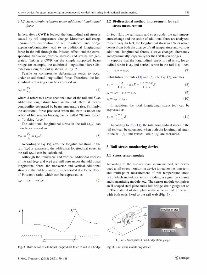
and transmitting module, etc. The sensor module comprises
an H-shaped steel plate and a full-bridge strain gauge set on
it. The material of steel plate is the same as that of the rail,
with both ends fixed to the rail web (Fig. 3).
Fig. 2 Distribution of additional longitudinal force of rail in a bridge
1. Rail; 2 Steel plate; 3 Full-bridge strain gauge
1
23
Installation area
Sensor area
Fig. 3 Rail stress monitoring device
A new device for stress monitoring in continuously welded rails using bi-directional strain method 181
123J. Mod. Transport. (2018) 26(3):179–188
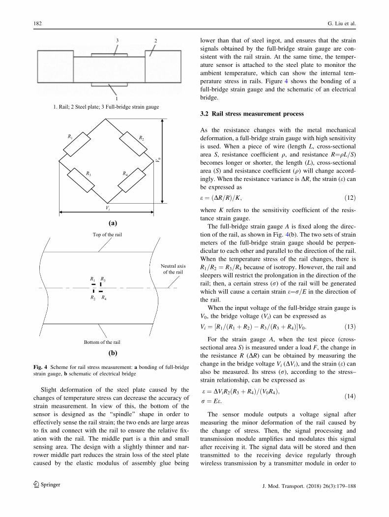
Slight deformation of the steel plate caused by the
changes of temperature stress can decrease the accuracy of
strain measurement. In view of this, the bottom of the
sensor is designed as the ‘‘spindle’’ shape in order to
effectively sense the rail strain; the two ends are large areas
to fix and connect with the rail to ensure the relative fix-
ation with the rail. The middle part is a thin and small
sensing area. The design with a slightly thinner and nar-
rower middle part reduces the strain loss of the steel plate
caused by the elastic modulus of assembly glue being
lower than that of steel ingot, and ensures that the strain
signals obtained by the full-bridge strain gauge are con-
sistent with the rail strain. At the same time, the temper-
ature sensor is attached to the steel plate to monitor the
ambient temperature, which can show the internal tem-
perature stress in rails. Figure 4 shows the bonding of a
full-bridge strain gauge and the schematic of an electrical
bridge.
3.2 Rail stress measurement process
As the resistance changes with the metal mechanical
deformation, a full-bridge strain gauge with high sensitivity
is used. When a piece of wire (length L, cross-sectional
area S, resistance coefficient q, and resistance R¼qL=S)becomes longer or shorter, the length (L), cross-sectional
area (S) and resistance coefficient (q) will change accord-
ingly. When the resistance variance is DR, the strain (e) canbe expressed as
e ¼ ðDR=RÞ=K; ð12Þ
where K refers to the sensitivity coefficient of the resis-
tance strain gauge.
The full-bridge strain gauge A is fixed along the direc-
tion of the rail, as shown in Fig. 4(b). The two sets of strain
meters of the full-bridge strain gauge should be perpen-
dicular to each other and parallel to the direction of the rail.
When the temperature stress of the rail changes, there is
R1=R2 ¼ R3=R4 because of isotropy. However, the rail and
sleepers will restrict the prolongation in the direction of the
rail; then, a certain stress (r) of the rail will be generated
which will cause a certain strain e¼r=E in the direction of
the rail.
When the input voltage of the full-bridge strain gauge is
V0, the bridge voltage (Vi) can be expressed as
Vi ¼ ½R1=ðR1 þ R2Þ � R3=ðR3 þ R4Þ�V0: ð13Þ
For the strain gauge A, when the test piece (cross-
sectional area S) is measured under a load F, the change in
the resistance R (DR) can be obtained by measuring the
change in the bridge voltage Vi (DVi), and the strain (e) canalso be measured. Its stress (r), according to the stress–
strain relationship, can be expressed as
e ¼ DViR2ðR3 þ R4Þ=ðV0R4Þ;r ¼ Ee:
ð14Þ
The sensor module outputs a voltage signal after
measuring the minor deformation of the rail caused by
the change of stress. Then, the signal processing and
transmission module amplifies and modulates this signal
after receiving it. The signal data will be stored and then
transmitted to the receiving device regularly through
wireless transmission by a transmitter module in order to
(a)
(b)Bottom of the rail
R1
R2
R3
R4
Neutral axisof the rail
Top of the rail
Vi
V 0
R1 R2
R3 R4
1. Rail; 2 Steel plate; 3 Full-bridge strain gauge1
23
Fig. 4 Scheme for rail stress measurement: a bonding of full-bridge
strain gauge, b schematic of electrical bridge
182 G. Liu et al.
123 J. Mod. Transport. (2018) 26(3):179–188
realize long-term and multi-point monitoring of changes in
rail stress.
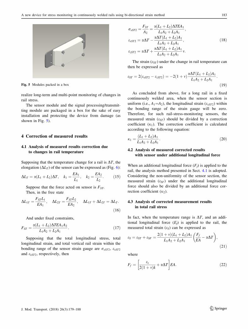
The sensor module and the signal processing/transmit-
ting module are packaged in a box for the sake of easy
installation and protecting the device from damage (as
shown in Fig. 5).
4 Correction of measured results
4.1 Analysis of measured results correction due
to changes in rail temperature
Supposing that the temperature change for a rail is DT , theelongation (DLT ) of the sensor can be expressed as (Fig. 6):
DLT ¼ aðL1 þ L2ÞDT ; k1 ¼EA1
L1; k2 ¼
EA2
L2: ð15Þ
Suppose that the force acted on sensor is FST.
Then, in the free state
DL1T ¼ FSTL1
EA1
; DL2T ¼ FSTL2
EA2
; DL1T þ DL2T ¼ DLT :
ð16Þ
And under fixed constraints,
FST ¼ aðL1 þ L2ÞDTEA1A2
L1A2 þ L2A1
: ð17Þ
Supposing that the total longitudinal stress, total
longitudinal strain, and total vertical rail strain within the
bonding range of the sensor strain gauge are rxST2, exST2and ezST2, respectively, then
rxST2 ¼FST
A2
¼ aðL1 þ L2ÞDTEA1
L1A2 þ L2A1
;
exST2 ¼ aDT � aDTðL1 þ L2ÞA1
L1A2 þ L2A1
;
ezST2 ¼ aDT þ aDTðL1 þ L2ÞA1
L1A2 þ L2A1
m:
ð18Þ
The strain (eST ) under the change in rail temperature can
then be expressed as
eST ¼ 2ðexST2 � ezST2Þ ¼ �2ð1þ mÞ aDTðL1 þ L2ÞA1
L1A2 þ L2A1
:
ð19Þ
As concluded from above, for a long rail in a fixed
continuously welded area, when the sensor section is
uniform (i.e., A1¼A2), the longitudinal strain (exST2) withinthe bonding range of the strain gauge will be zero.
Therefore, for such rail-stress-monitoring sensors, the
measured strain (eST ) should be divided by a correction
coefficient (j1). The correction coefficient is calculated
according to the following equation:
j1 ¼L1 þ L2ð ÞA1
L1A2 þ L2A1
: ð20Þ
4.2 Analysis of measured corrected results
with sensor under additional longitudinal force
When an additional longitudinal force (Ff) is applied to the
rail, the analysis method presented in Sect. 4.1 is adopted.
Considering the non-uniformity of the sensor section, the
measured strain (eSF) under the additional longitudinal
force should also be divided by an additional force cor-
rection coefficient (j2).
4.3 Analysis of corrected measurement results
in total rail stress
In fact, when the temperature range is DT , and an addi-
tional longitudinal force (Ef) is applied to the rail, the
measured total strain (eS) can be expressed as
eS ¼ eST þ eSF ¼ 2ð1þ mÞðL1 þ L2ÞA1
L1A2 þ L2A1
Ff
EA� aDT
� �;
ð21Þ
where
Ff ¼es
2 1þ mð Þk þ aDT
� �EA: ð22Þ
Fig. 5 Modules packed in a box
A new device for stress monitoring in continuously welded rails using bi-directional strain method 183
123J. Mod. Transport. (2018) 26(3):179–188

(a)
(b)
R1 R3 R2 R4
Z
X
R1
R2R3
R4
(c)
Cross-sectionalarea A1
Cross-sectionalarea A2
L1 L2
FFR1
R2R3
R4
Cross-sectionalarea A1
Cross-sectionalarea A2
L1 L2
R1
R2R3
R4
Surface for fixingand connecting
with the rail
Cross-sectionalarea A1
Cross-sectionalarea A2
L1/2 L1/2L2
R1
R2R3
R4
Fig. 6 Schematic diagram of the test device on a steel plate. Front (a) and top (b) views of steel plate, and (c) designed size of the sensor module
184 G. Liu et al.
123 J. Mod. Transport. (2018) 26(3):179–188

5 Test of rail stress using monitoring sensor
5.1 Test of basic temperature stress in rail
A temperature was set and an axial force was loaded on a
rail installed with a stress-monitoring sensor (Fig. 7). The
measured results were compared with the theoretical
solutions.
The CHN60 rail with a length of 60 cm was used in the
test, which is based on the distance of 60 cm between
consecutive rail fasteners in Chinese Code for Design of
Railway Continuous Welded Rail TB 10015-2012(J
1586-2013). To simulate the locked state of CWR, we set
the universal testing machine (1,000 kN) in a fixed state
and installed the rail between the two loading heads of the
machine to avoid longitudinal strain during the test. In
addition, we used external heat source to heat the rail, and
measured the rail stress at different temperatures. The test
device is shown in Fig. 8.
5.2 Test of additional longitudinal stress in rail
An axial load was exerted on the test rail by a jack. Then,
the additional longitudinal stress was measured with the
rail stress monitoring sensor installed on the rail web [29].
The measured additional stress was compared with the
theoretically calculated additional stress.
5.3 Test results
5.3.1 Test of basic temperature stress in rail
The initial rail temperature was set as T0 ¼ 0 and Tci the
actual rail temperature. For the CWRs, it is usually
assumed that the stress-free temperature is a constant value
in the existing CWR design and calculation. The author
thus conducts relevant research based on this assumption.
When the rail temperature rises from T0 to Tci, the rail
stress (ri) is
ri ¼ aEðTci � T0Þ; ð23Þ
where a refers to the rail’s coefficient of linear expansion
and E the rail’s elastic modulus.
Using the rail-stress-monitoring sensor, the longitudinal
force in the rail was measured under different temperatures
and the results were compared with theoretical values
(Table 1).
A comparison was made between the rail stress mea-
sured with the stress sensor under different changes in the
temperature and theoretical values (Fig. 9).
As can be seen from Fig. 9, the three lines basically
overlap, showing the following facts.
1. There are minor errors between the measured rail
stresses under different changes in temperature, and
the maximum error rate is 8.76%.
2. Two groups of the test results are in good agreement,
demonstrating that the rail stress monitoring sensor
works in a stable and reliable state.
As Fig. 10 shows, the measuring errors increase grad-
ually with the change in temperature. For example, when
the change in rail temperature reaches 10 �C, the error
result is approximately 1.5 MPa. When the rail temperature
stresses are measured with resistance strain gauges, the
thermal strain of the strain gauges should not be neglected.
As previously mentioned, with sensitive directions being
perpendicular to each other, the resistance wires of full-
bridge gauges were parallel and perpendicular to the
directions of the rail, thus the thermal strains of the four
strain gauges were able to counteract with each other.
However, considering the uneven distribution of the actual
temperature for the rail section, measuring errors still
Fig. 7 Rail stress-monitoring sensor
Fig. 8 The universal testing machine in a temperature box
A new device for stress monitoring in continuously welded rails using bi-directional strain method 185
123J. Mod. Transport. (2018) 26(3):179–188
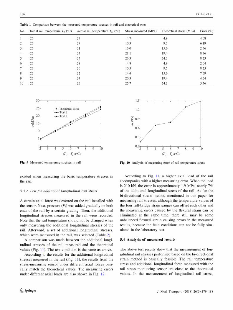
existed when measuring the basic temperature stresses in
the rail.
5.3.2 Test for additional longitudinal rail stress
A certain axial force was exerted on the rail installed with
the sensor. Next, pressure (Fi) was added gradually on both
ends of the rail by a certain grading. Then, the additional
longitudinal stresses measured in the rail were recorded.
Note that the rail temperature should not be changed when
only measuring the additional longitudinal stresses of the
rail. Afterward, a set of additional longitudinal stresses,
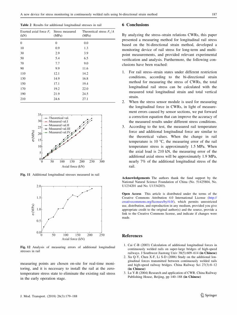
which were measured in the rail, was selected (Table 2).
A comparison was made between the additional longi-
tudinal stresses of the rail measured and the theoretical
values (Fig. 11). The test condition is the same as above.
According to the results for the additional longitudinal
stresses measured in the rail (Fig. 11), the results from the
stress-measuring sensor under different axial forces basi-
cally match the theoretical values. The measuring errors
under different axial loads are also shown in Fig. 12.
According to Fig. 11, a higher axial load of the rail
accompanies with a higher measuring error. When the load
is 210 kN, the error is approximately 1.9 MPa, nearly 7%
of the additional longitudinal stress of the rail. As for the
bi-directional strain method mentioned in this paper for
measuring rail stresses, although the temperature values of
the four full-bridge strain gauges can offset each other and
the measuring errors caused by the flexural strain can be
eliminated at the same time, there still may be some
unbalanced flexural strain causing errors in the measured
results, because the field conditions can not be fully sim-
ulated in the laboratory test.
5.4 Analysis of measured results
The above test results show that the measurement of lon-
gitudinal rail stresses performed based on the bi-directional
strain method is basically feasible. The rail temperature
stress and additional longitudinal force measured with the
rail stress monitoring sensor are close to the theoretical
values. In the measurement of longitudinal rail stress,
2 3 4 5 6 7 8 9 100.0
0.3
0.6
0.9
1.2
1.5
σ( M
Pa)
(Tci – T0) (°C)
Fig. 10 Analysis of measuring error of rail temperature stress
2 3 4 5 6 7 8 9 100
5
10
15
20
25
30
(Tci – T0) (°C)
σ(M
Pa)
Theoretical valueTest ITest II
Fig. 9 Measured temperature stresses in rail
Table 1 Comparison between the measured temperature stresses in rail and theoretical ones
No. Initial rail temperature T0 (�C) Actual rail temperature Tci (�C) Stress measured (MPa) Theoretical stress (MPa) Error (%)
1 25 27 4.7 4.9 4.08
2 25 29 10.3 9.7 6.19
3 25 31 16.0 15.6 2.56
4 25 33 21.1 19.4 8.76
5 25 35 26.3 24.3 8.23
6 26 28 4.8 4.9 2.04
7 26 30 10.5 9.7 8.25
8 26 32 14.4 15.6 7.69
9 26 34 20.3 19.4 4.64
10 26 36 25.7 24.3 5.76
186 G. Liu et al.
123 J. Mod. Transport. (2018) 26(3):179–188
measuring points are chosen on-site for real-time moni-
toring, and it is necessary to install the rail at the zero-
temperature stress state to eliminate the existing rail stress
in the early operation stage.
6 Conclusions
By analyzing the stress–strain relations CWRs, this paper
presented a measuring method for longitudinal rail stress
based on the bi-directional strain method, developed a
monitoring device of rail stress for long-term and multi-
point measurements, and provided relevant experimental
verification and analysis. Furthermore, the following con-
clusions have been reached:
1. For rail stress–strain states under different restriction
conditions, according to the bi-directional strain
method for measuring the stress of CWRs, the total
longitudinal rail stress can be calculated with the
measured total longitudinal strain and total vertical
strain.
2. When the stress sensor module is used for measuring
the longitudinal force in CWRs, in light of measure-
ment errors caused by sensor sections, we put forward
a correction equation that can improve the accuracy of
the measured results under different stress conditions.
3. According to the test, the measured rail temperature
force and additional longitudinal force are similar to
the theoretical values. When the change in rail
temperature is 10 �C, the measuring error of the rail
temperature stress is approximately 1.5 MPa. When
the axial load is 210 kN, the measuring error of the
additional axial stress will be approximately 1.9 MPa,
nearly 7% of the additional longitudinal stress of the
rail.
Acknowledgements The authors thank the fund support by the
National Natural Science Foundation of China (No. 51425804, No.
U1234201 and No. U1334203).
Open Access This article is distributed under the terms of the
Creative Commons Attribution 4.0 International License (http://
creativecommons.org/licenses/by/4.0/), which permits unrestricted
use, distribution, and reproduction in any medium, provided you give
appropriate credit to the original author(s) and the source, provide a
link to the Creative Commons license, and indicate if changes were
made.
References
1. Cai C-B (2003) Calculation of additional longitudinal forces in
continuously welded rails on super-large bridges of high-speed
railways. J Southwest Jiaotong Univ 38(5):609–614 (in Chinese)2. Xu Q-Y, Chen X-F, Li S-D (2006) Study on the additional lon-
gitudinal forces transmitted between continuously welded rails
and high-speed railway bridges. China Railway Sci 27(3):8–12
(in Chinese)3. Lu Y-R (2004) Research and application of CWR. China Railway
Publishing House, Beijing, pp 140–188 (in Chinese)
Table 2 Results for additional longitudinal stresses in rail
Exerted axial force Fi
(kN)
Stress measured
(MPa)
Theoretical stress Fi=A(MPa)
0 0 0.0
10 0.9 1.3
30 2.9 3.9
50 5.4 6.5
70 7.7 9.0
90 9.9 11.6
110 12.1 14.2
130 14.9 16.8
150 17.1 19.4
170 19.2 22.0
190 21.9 24.5
210 24.6 27.1
0 50 100 150 200 250 3000
5
10
15
20
25
30
35
σ(M
Pa)
Axial force (kN)
Theoretical val.Measured val.IMeasured val.IIMeasured val.IIIMeasured val.IV
Fig. 11 Additional longitudinal stresses measured in rail
0 50 100 150 200 2500.0
0.5
1.0
1.5
2.0
σ(M
Pa)
Axial force (kN)
Fig. 12 Analysis of measuring errors of additional longitudinal
stresses in rail
A new device for stress monitoring in continuously welded rails using bi-directional strain method 187
123J. Mod. Transport. (2018) 26(3):179–188

4. Rail Safety & Standards Board (2008) Management of stressed
continuously welded track-rail stress-free temperature measure-
ment techniques. RSSB Research and Development Programme,
London
5. Harrison H, McWilliams R, Kish A (2007) Handling CWR
thermal forces. Railway Track and Structures, New York,
pp 42–45
6. Bartosiewicz A et al (1999) Experiences in the application of
ultrasonic stress measurements for railway industry. Foreign
Rolling Stock 6:31–36
7. Wang P, Gao Y-L, Yang YR et al (2013) Experimental studies
and new feature extractions of MBN for stress measurement on
rail tracks. IEEE Trans Magn 8(49):4858–4864 (in Chinese)8. Gokhale S (2007) Determination of applied stresses in rails using
the acoustoelastic effect of ultrasonic waves. Texas A&M
University, Texas
9. ASME (2007) A novel method for estimating the neutral tem-
perature of continuously welded rails. In: ASME rail trans-
portation division fall technical conference, Sep 11–12, 2007,
pp 105–115
10. Peng X-D, Ding J-X (2006) Study on monitoring thermal stresses
in continuously welded rails with LCR waves. J Univ Electron
Sci Technol China 10(35):844–847 (in Chinese)11. Filograno ML, Corredera GP et al (2012) Real-time monitoring
of railway traffic using fiber bragg grating sensors. IEEE Sens J
12(1):85–92
12. Tunna J (2000) Vertical rail stiffness equipment (VERSE) trials.
Letter Report for Vortex International Transportation Technology
Center, Inc. (TTCI), Pueblo, CO
13. Kelleher J, Prime MB, Buttle D et al (2003) The measurement of
residual stress in railway rails by diffraction and other methods.
J Neurosci Res 11(4):187–193
14. Hayes AP (2008) MAPS-SFT, a new tool in the infrastructure
manager’s toolbox. In: 2008 4th IET international conference on
railway condition monitoring, 18–20 June 2008, ISSN:
0537-9989
15. Hurlebaus S (2011) Determination of longitudinal stress in rails.
Final Report Safety IDEA Project 15, Transportation research
Board, Washington, DC
16. Nucera C, Lanza di Scalea F (2014) Nondestructive measurement
of neutral temperature in continuous welded rails by nonlinear
ultrasonic guided waves. J Acoust Soc Am 136(5):2561–2574
17. Zhu X, Lanza di Scalea F (2017) Thermal stress measurement in
continuous welded rails using the hole-drilling method. Exp
Mech 57:165. https://doi.org/10.1007/s11340-016-0204-8
18. Song X-W (2012) Error analysis and improvement of rail lon-
gitudinal force measurement by electrical measuring method for
strain. Dalian University of Technology, Dalian (in Chinese)19. Zhang F-S (2012) Error analysis and improvement in monitoring
the stress-free temperature of continuous welded rails by strain-
temperature measurement method. Dalian University of Tech-
nology, Dalian (in Chinese)20. Feng S-M (2012) Monitoring and analysis of longitudinal forces
from CWRs in ballastless tracks on long spanning bridges for
high-speed railways. East China Jiaotong University, Nanchang
(in Chinese)21. Feng S-M, Lei X-Y, Zhang P-F et al (2011) Remote monitoring
and analysis of additional contractility from CWRs on bridges.
J East China Jiaotong Univ 28(2):1–5 (in Chinese)22. AEA Technology Rail (2006) Findings from the investigation of
SFE measurement techniques. AEA Technology Rail, London
23. Li Y-H (2013) Research on wireless monitoring system hardware
for distributed rail stress. Dalian University of Technology,
Dalian (in Chinese)24. Wang P, Xie K, Shao L et al (2015) Longitudinal force mea-
surement in continuous welded rail with bi-directional FBG strain
sensors. Smart Mater Struct 25(1):1–10
25. Wang P, Xie K, Chen R, Shao L et al (2016) Test verification and
application of a longitudinal thermal force testing method for
long seamless rails using FBG strain sensor. J Sens. Article ID
3917604
26. Wang P, Xu J, Xie K et al (2016) Numerical simulation of rail
profiles evolution in the switch panel of a railway turnout [J].
Wear 366–367:105–115
27. Wang B, Xie K, Xiao J, Wang P (2016) Test principle and test
scheme of longitudinal force in continuous welded rail using
resistance strain gauge. J Southwest Jiaotong Univ 51(1):43–49
28. Ding J-X (2012) Monitoring device for rail thermal stress, China,
CN201120140230. X[P]. 2012-01-11 (in Chinese)29. Yan B, Dai G, Guo W, Xu Q (2015) Longitudinal force in con-
tinuously welded rail on long-span tied arch continuous bridge
carrying multiple tracks. J Central South Univ 22(05):2001–2006
188 G. Liu et al.
123 J. Mod. Transport. (2018) 26(3):179–188


![Comparative Residual Stress Analysis in Welded …R. Melicher ][4 discussed residual stress estimations in circumferential welds. The effect of nonlinearity in the material conditions](https://img.pdfslide.us/doc/110x75/5f0f723b7e708231d44433d2/comparative-residual-stress-analysis-in-welded-r-melicher-4-discussed-residual.jpg)


![TRAIN SYSTEM [CP2] - Department of Planning, …...- where rails are continuously welded and curves are properly transitioned (except at platforms) - where rails are not continuously](https://img.pdfslide.us/doc/110x75/5e766a9b9e521f70487e93ef/train-system-cp2-department-of-planning-where-rails-are-continuously.jpg)