Embed Size (px)
Citation preview
I J C T A, 9(8), 2016, pp. 3431-3436© International Science Press
A Multi-band Slot Antenna forWireless SystemsI. Pugazharasan* and C. Mahendran**
ABSTRACT
A design of multi-band slot antenna for the application of wireless systems is proposed. A Rectangular slot with anarea of 48 � 18 mm2, a T-shaped feed patch and the two E-shaped stubs, are responsible for the generation of thefrequency bands in the antenna. A substrate used in the antenna is FR4, which is readily available in the market. Amicro-strip feed technique is used to feed the antenna. The rectangular slot is used in the antenna, which is easy tofabricate. The antenna is studied and designed using FDTD numerical method. The response of the length of slotand geometry of the feeder line on the resonant frequency of this structure are studied.The parameters like Radiationpattern, Return loss, and VSWR of the proposed antenna are analyzed. The antenna is designed to cover theapplications such as IEEE 802.11b&g WLAN systems, WiMAX system and IEEE 802.11a WLAN system. Theproposed antenna has VSWR value less than 2 in the operating frequency bands.
Keywords: Stub, Patch antenna, Return loss, Radiation pattern.
1. INTRODUCTION
Modern wireless systems are placing greater emphasis on antenna designs for future development incommunication technology because of antenna being a key element in the whole communication system.Communication between human was first by sound through voice. The optical communication devices,utilized the light portion of the electromagnetic spectrum. With the blooming of modern wirelesscommunication technologies, a wireless communication antenna is required to cover a very wide frequencybandwidth or several frequency bands and is expected to be small in size. The technologies of wirelesscommunication system have been rapidly ever growing demands for broad band service and transmissionspeeds to support multimedia, image, speech and data communication. In order to response the rapidlygrowing demands, the antenna should be responsible for many frequency bands with simple structure,compact size and easy integration. Traditionally, single or dual band antennas are used to cover the one ortwo applications at a time. So we need two or more antennas in a device to cover the various applications.This will cause increase in space occupied by the antenna and also increase the need for power to theantennas.In order to overcome this problem, multiband antenna can be used where a single antenna canoperate at many frequency bands. Microstrip patch antenna due to its advantages such as low weight, lowprofile planner configuration, and small size, low fabrication cost etc. is very well suited for wirelessapplications. The bandwidth of Microstrip patch antenna can be improved by various methods like bycutting slot and increasing substrate height, low dielectric constant of substrate, various impedance matching,feeding techniques, multiple resonators and multilayer structure.This antenna was used to cover theapplication at 2.4 and 3.4 GHz for WiMAX. The antenna structure has a stem, which is used to connect thetwo branchesby X. L. Sun, et al., [1]. The antenna was designed with a reconfigurable single folded slot,which has a metal strips to manipulate the ground size around the slot by Dimitrios E. Anagnostou, et al.,[2]. In this antenna, the resonant frequency is change by changing the perimeter of the slot. Thecompact
* PG Scholar, Alagappa Chettiar College of Engineering and Technology, Karaikudi, Tamilnadu, Email: [email protected]
** Faculty of ECE, Alagappa Chettiar College of Engineering and Technology, Karaikudi, Tamilnadu, Email: [email protected]
3432 I. Pugazharasan and C. Mahendran
ultra-wideband (UWB) antenna had an octagonal slot, which is fed by stepped and bevelled rectangularpatch to cover the ultra-wide band frequency ranges from (3.1 – 10.6 GHz) by M. Bod, et al., [3]. Theplanar slot antennas turn out to be the most popular candidates contributing in low profile, wider impedancebandwidth, suitable to be printed on the system circuit board of portable devices, and easily fabricated atlow cost for practical applications by J. H. Lu, et al., [4]. The antenna was designed with an H-shapedradiator, a CPW and a Varactor diode, which was used to connect the upper and lower arms of the radiatorfor re-configurability. The operating frequency and mode of the antenna was selected electronically byusing varactor diode by H.F. AbuTarboush et al., [5]. The antenna was designed with four branches on thetop layer and a parasitic element on the bottom layer of the antenna, which is used to cover the applicationssuch as GSM, DCS, PCS, UMTS, Bluetooth, WLAN and Wi-MAX.byW.J. Liao, et al., [6].
The proposed antenna has a rectangular patch with two shorting pins. Four open stubs are attached to therectangular patch through four pin diodes, and the ability of switchingthe antenna operating frequency is achievedby using dual in-line package switches to control the states of the diodes, whereby eight different operating bandsover a wide range of frequencies can be switched by T.Y. Han, et al., [7]. The proposed antenna is simplycomposed of a -shaped stub resonator and a monopole radiator. The special asymmetry h-shaped stub extendedfrom the ground can achieve a new resonance as well as reduced antenna size by W. Hu, et al., [8].In this paper,we have presented the use of microstrip patch antenna with rectangular slot for multiband applications, withcompact size and low return loss. The VSWR parameter was found to be less than 2 in the operating frequencies.
2. DESIGN OF THE ANTENNA
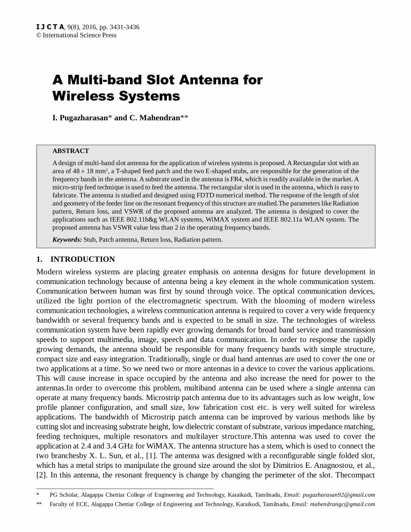
The Microstrip Patch Antenna with a Rectangular Patch, is shown in the fig. 1. The patch has a slot and amicrostrip feed with impedance of 50 ohm. The slot consist of a T-shaped stub and a two E-shaped stubs onboth sides of the slot. The ground plane and the patch are designed with pure copper. The Substrate is made ofthe FR-4 (lossy). The dimensions were selected to meet the specifications of the desired narrow band antenna.
Figure 1: Top View of the antenna.
A Multi-band Slot Antenna for Wireless Systems 3433
Thusthe designed antenna can be used in application areas like Industrial, Scientific and Medical band, WiMAX(Worldwide Interoperability for Microwave Access) and WLAN (Wireless Local Area Network) applications.Proposed Narrow band antenna with rectangular slot and stubs, scattering parameter and radiation pattern aredesigned and simulated. By using the tools in the FDTD simulator, the Microstrip patch antenna is constructed.The patch and the ground is composed of pure electrical conductor material. The substrate is filled with thedielectric material of FR-4 substrate. The dielectric material is having the permittivity of 4.3. A rectangularpatch was etched on the top portion of patch one side of FR4 substrate with initial dimensions of length L
1 and
width W1. The thickness of the FR4 substrate in the proposed antenna is 0.8 mm. A 50 ohm microstrip line of
width g2 and length W
2 was adopted for feeding the patch. For this proposed antenna microstrip feeding is
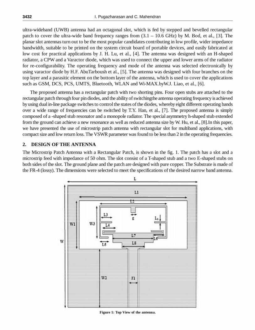
used. The antenna can generate three frequency bands at 2.4, 3.5 and 5.4 GHz for different wireless applications.The dimension of the proposed antenna is shown in the table1. The antenna structure as shown in Fig.1 andFig. 2. The Thickness of the substrate used is 0.8 mm. The T-shaped feed line, which is used to feed theantenna, is placed on the top patch of the proposed antenna.
3. ANTENNA STUDY
The return loss parameter is used to study the effect of change frequency bands due to the change in theantenna radiating elements. The parametric analysis of the antenna is carried out by varying the size of theactive radiating elements, which is sensible to the particular frequency bands. The frequency band of theantenna is affected by some parameters of the antenna such as L3, W3 and g. The change in dimensions ofthese parameters leads to the shift in frequency band of the antenna. The FDTD method is used to study theeffect of shift in operating frequency bands due to the change in the antenna parameters. In this proposedantenna, the slot is etched at the top layer of the antenna. This slot responsible for the generation of resonantfrequency. The E-shaped stubs and the T-shaped stubs in the slot, will generate the other operating frequencies.The change in the dimensions of the active elements in the slot, will affect the frequency bands. Fig. 1shows the top view of the antenna with the dimension of L � W (57 � 45 mm2). The slot is etched on the toplayer of the antenna with dimension of (48 � 18 mm2).
Figure 2: (a) Side View (b) Bottom view of the antenna.
(b)(a)
Table 1Dimensions of the antenna in mm
L W L1 W1 L2 W2 L3 L457 45 48 18 20 21.6 5.5 5.5L5 L6 L7 L8 F1 L
ST
Sg
4 4.5 18 10 4 0.5 0.8 2
3434 I. Pugazharasan and C. Mahendran
4. RESULT AND DISCUSSION
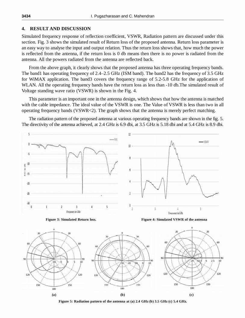
Simulated frequency response of reflection coefficient, VSWR, Radiation pattern are discussed under thissection. Fig. 3 shows the simulated result of Return loss of the proposed antenna. Return loss parameter isan easy way to analyse the input and output relation. Thus the return loss shows that, how much the poweris reflected from the antenna, if the return loss is 0 db means then there is no power is radiated from theantenna. All the powers radiated from the antenna are reflected back.
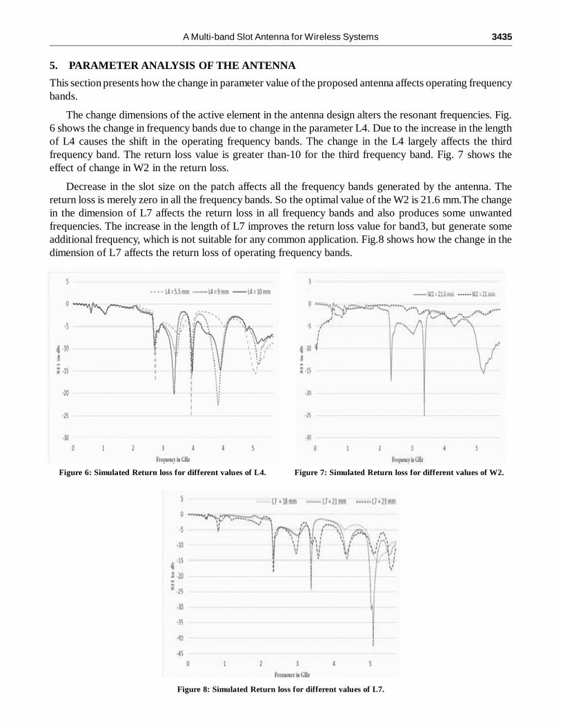
From the above graph, it clearly shows that the proposed antenna has three operating frequency bands.The band1 has operating frequency of 2.4–2.5 GHz (ISM band). The band2 has the frequency of 3.5 GHzfor WiMAX application. The band3 covers the frequency range of 5.2-5.8 GHz for the application ofWLAN. All the operating frequency bands have the return loss as less than -10 db.The simulated result ofVoltage standing wave ratio (VSWR) is shown in the Fig. 4.
This parameter is an important one in the antenna design, which shows that how the antenna is matchedwith the cable impedance. The ideal value of the VSWR is one. The Value of VSWR is less than two in alloperating frequency bands (VSWR<2). The graph shows that the antenna is merely perfect matching.
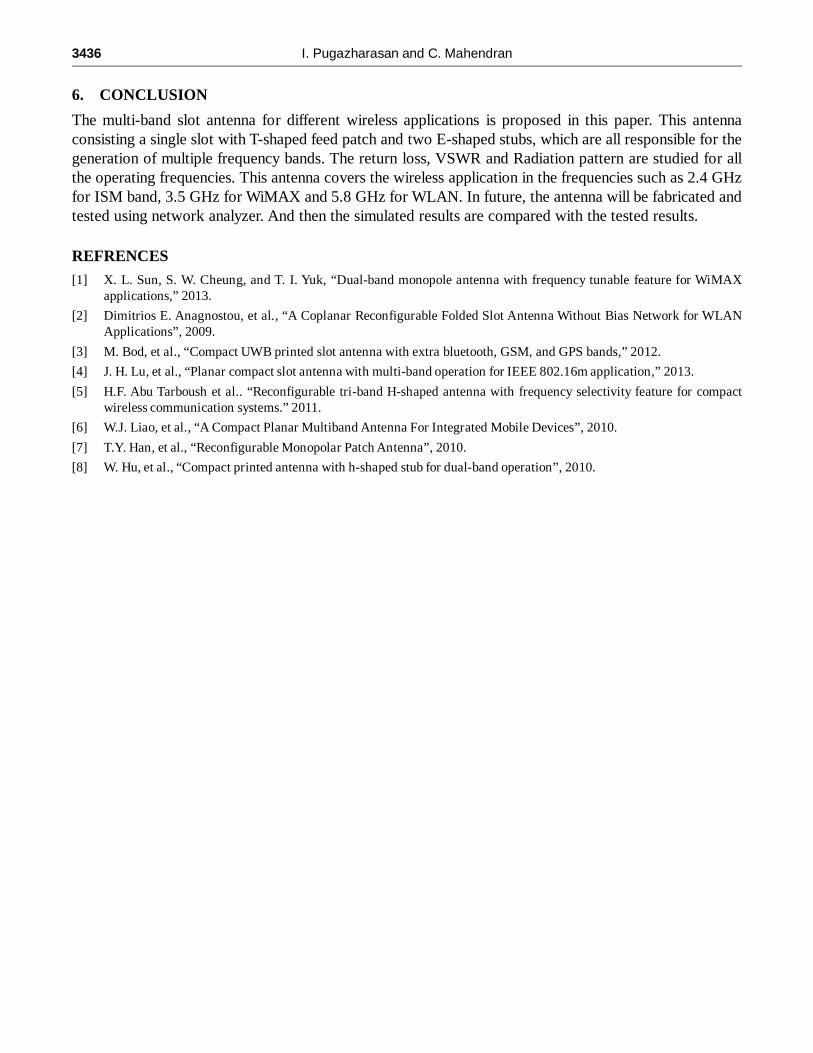
The radiation pattern of the proposed antenna at various operating frequency bands are shown in the fig. 5.The directivity of the antenna achieved, at 2.4 GHz is 6.9 dbi, at 3.5 GHz is 5.18 dbi and at 5.4 GHz is 8.9 dbi.
Figure 3: Simulated Return loss.
(a) (c)(b)
Figure 4: Simulated VSWR of the antenna
Figure 5: Radiation pattern of the antenna at (a) 2.4 GHz (b) 3.5 GHz (c) 5.4 GHz.
A Multi-band Slot Antenna for Wireless Systems 3435
5. PARAMETER ANALYSIS OF THE ANTENNA
This section presents how the change in parameter value of the proposed antenna affects operating frequencybands.
The change dimensions of the active element in the antenna design alters the resonant frequencies. Fig.6 shows the change in frequency bands due to change in the parameter L4. Due to the increase in the lengthof L4 causes the shift in the operating frequency bands. The change in the L4 largely affects the thirdfrequency band. The return loss value is greater than-10 for the third frequency band. Fig. 7 shows theeffect of change in W2 in the return loss.
Decrease in the slot size on the patch affects all the frequency bands generated by the antenna. Thereturn loss is merely zero in all the frequency bands. So the optimal value of the W2 is 21.6 mm.The changein the dimension of L7 affects the return loss in all frequency bands and also produces some unwantedfrequencies. The increase in the length of L7 improves the return loss value for band3, but generate someadditional frequency, which is not suitable for any common application. Fig.8 shows how the change in thedimension of L7 affects the return loss of operating frequency bands.
Figure 6: Simulated Return loss for different values of L4. Figure 7: Simulated Return loss for different values of W2.
Figure 8: Simulated Return loss for different values of L7.
3436 I. Pugazharasan and C. Mahendran
6. CONCLUSION
The multi-band slot antenna for different wireless applications is proposed in this paper. This antennaconsisting a single slot with T-shaped feed patch and two E-shaped stubs, which are all responsible for thegeneration of multiple frequency bands. The return loss, VSWR and Radiation pattern are studied for allthe operating frequencies. This antenna covers the wireless application in the frequencies such as 2.4 GHzfor ISM band, 3.5 GHz for WiMAX and 5.8 GHz for WLAN. In future, the antenna will be fabricated andtested using network analyzer. And then the simulated results are compared with the tested results.
REFRENCES
[1] X. L. Sun, S. W. Cheung, and T. I. Yuk, “Dual-band monopole antenna with frequency tunable feature for WiMAXapplications,” 2013.
[2] Dimitrios E. Anagnostou, et al., “A Coplanar Reconfigurable Folded Slot Antenna Without Bias Network for WLANApplications”, 2009.
[3] M. Bod, et al., “Compact UWB printed slot antenna with extra bluetooth, GSM, and GPS bands,” 2012.
[4] J. H. Lu, et al., “Planar compact slot antenna with multi-band operation for IEEE 802.16m application,” 2013.
[5] H.F. Abu Tarboush et al.. “Reconfigurable tri-band H-shaped antenna with frequency selectivity feature for compactwireless communication systems.” 2011.
[6] W.J. Liao, et al., “A Compact Planar Multiband Antenna For Integrated Mobile Devices”, 2010.
[7] T.Y. Han, et al., “Reconfigurable Monopolar Patch Antenna”, 2010.
[8] W. Hu, et al., “Compact printed antenna with h-shaped stub for dual-band operation”, 2010.
![Ka-Band SIW-fed Slot Array Antennahome.agh.edu.pl/~rydosz/MIKON/M25.5.pdf · Ka-Band SIW-fed Slot Array Antenna H. S. Farahani, ... Jan 2011. [3] H. S ... “The design of slot arrays](https://img.pdfslide.us/doc/110x75/5b2587787f8b9a353f8b4ff4/ka-band-siw-fed-slot-array-rydoszmikonm255pdf-ka-band-siw-fed-slot-array.jpg)


![Compact Triangular Slot Antenna with Improved … · Compact Triangular Slot Antenna with Improved ... .Zeland IE3D [18] ... A. Balanis, “Advanced Engineering Electromagnetics”,](https://img.pdfslide.us/doc/110x75/5acbed9e7f8b9aa1518bb8a7/compact-triangular-slot-antenna-with-improved-triangular-slot-antenna-with-improved.jpg)