Embed Size (px)
Citation preview

Abstract—This paper presents the initial development of a
hardware-software modular and scalable architecture based on
low cost FPGA and ARM processor development boards to
implement an Inertial Guidance System, Computer Vision,
Stochastic Optimization and Deep Neural Networks for a man
portable AUV designed to enable operations to water depths as
great as 4000 m. The software is coded by VHDL language
running on an FPGA and C/C++ scripts running on an
Embedded System. The FPGA and ARM processor are
contained in the same chip. The main purpose of the hardware-
software architecture is perform some complex tasks of a ROV
with human operators like identify sites of scientific interest
and make parking strategies to collect underwater samples. The
sites of scientific interest could be a new hydrothermal vent or
an unknown shipwreck. Also the mission can be reconfigured
onboard according to the relevant of the acquired data through
the vehicle’s sensors. Results from laboratory and AUV sea
trials are shown.
Index Terms—Autonomous Underwater Vehicle (AUV),
Deep Neural Networks (DNN), Embedded System, FPGA,
Stochastic Optimization.
I. INTRODUCTION
HE Deep Ocean Floor is an extreme and mostly
unknown environment, key tools to explore it are the
Autonomous Underwater (AUV) and ROV (Remotely
Operated Vehicle) [1]. Usually a ROV carries an array of
High Definition cameras that allow scientists closely
examine the sea floor and perform intricate tasks, examples:
identify a new specimen and capture it with a robotic arm or
track the plume coming from a hydrothermal vent [2]. A
typically work class ROV requires the support of a manned
vessel that can cost up to $50,000 per day and a initial
investment of $100,000 plus maintenance cost. These costs
limit the access to many institutions to this technology [3]. In
the other hand, Autonomous Underwater Vehicles are
untethered and can operate at sea for long term without the
support of a manned vessel. They have sophisticate onboard
computers and sensors to follow a preprogrammed path and
execute sequential behaviors scripted with a mission plan
user interface [4]. The AUVs intrinsically are not a real time
tool, the stored data are available when the vehicle is on the
Manuscript received March 24, 2017; revised April 10, 2017. A. Cadena is a Design Engineer at Universidad Estatal Península de
Santa Elena (UPSE), Avda. principal La Libertad - Santa Elena, Libertad, Ecuador. (e-mail: [email protected]).
sea surface. Some AUV include acoustic data link systems to
access key vehicle parameters and send messages with
mission updates while the vehicle is submerged [5].
Navigate near the sea floor, less than 1 m, is a challenging
task, ROV pilots make path adjustments to avoid potential
navigation hazards for the vehicle, especially on irregular
terrain. Routinary tasks of a team monitoring a ROV mission
are: get images of a specified object, identify biological,
archeological or geological features, track a chemical signal
to its source and generated parking strategies to collect
samples from the sea floor. These complex tasks are
executed by human operators and specialists in different
fields that could be marine biology, oceanography and
geology. Based on their knowledge and experience, they
take decisions to explore efficiently a scientific site of
interest. If an AUV can accomplish these complex tasks, the
exploration cost at high sea might decreases because two
components of a ROV system can be avoided, the winch-
tether and the control room. In this paper we purpose a low
cost hardware-software system architecture optimized for
small AUV to perform typical ROV deep sea exploration
tasks. This kind of AUV can be deployed from a sailing boat
at high sea, performing some tasks of an oceanographic
vessel equipped with ROV. Many non-governmental
organization dedicated for ocean conservation operate
sailing boats where might unable a full components
installation of a typical 4000m ROV system [6].
AUV mission-critical systems must be controlled by real
time embedded software that runs on an onboard computer
[7]. Some AUV navigate based on Strapdown Inertial
Navigation System and Computer Vision algorithms that
require high computational capacity [8]. The size and power
consumption of the onboard computer is a key factor of
AUV pressure housings design. AUV mission
reconfiguration, specimen identification and generation of
strategies for sampling could be based on Artificial
Intelligence (AI) and Machine Learning (ML) to deal with
uncertainties that appear in-situ [9]. Real Time identification
and tracking of an underwater specimen requires image
segmentation and pattern recognition [10]. Some computer
vision problems of segmentation and pattern recognition
require optimize a cost function that depends of a large set
of parameter. If the cost function is convex, locate the global
optimum is a very simple task. However typical computer
vision problems of underwater specimens with irregular
forms (jelly fish, piece of a shipwreck) are hard to formulate
A Modular Hardware-Software Architecture of an Autonomous Underwater Vehicle for Deep
Sea Exploration
A. Cadena
T
Proceedings of the World Congress on Engineering 2017 Vol I WCE 2017, July 5-7, 2017, London, U.K.
ISBN: 978-988-14047-4-9 ISSN: 2078-0958 (Print); ISSN: 2078-0966 (Online)
WCE 2017
in convex form, where is easy get trapped in local minima.
Therefore stochastic optimization algorithm must be used
[11]. Deep Neural Networks (DNN) have shown good
performance for pattern recognition and strategies
generation, even in complex table games like “Go” [12].
Usually DNN are implemented on GPU (Graphics
Processing Units). A GPU based implementation is not
suitable for a small underwater vehicle due its size and
power consumption that can excess 100 watts, a GPU
requires a CPU to work. FPGA are more suitable hardware
platforms for DNN implementation in small size vehicles,
there are several previous work of DNN and Convolutional
Neural Networks (CNN) implementation on FPGA [13].
We have developed a hardware-software architecture
using two FPGA-ARM development boards. On one board,
TERASIC DE0 nano, runs routines for Guidance,
Navigation and Control (GNC) and Computer Vision (CV),
the other board, TERASIC DE0 nano SoC, runs a Stochastic
Optimization unit and DNN based on parallel/sequential
implementation. The DE0 nano SoC has a FPGA and ARM
in the same chip. The main objective of this architecture is to
get the enough autonomy to perform the following complex
tasks: navigate on irregular terrain, get images of a specified
object based on its scientific relevance, identify
archeological, biological or geological features and
generated parking strategies to collect samples from the sea
floor and track a chemical signal to its source in order to
find a potential hydrothermal vent. In our initial approach
the entire machine intelligence was based on DNN but the
required computational capacity to analyze 4K images was
equivalent to 20 GPUs, impractical for a small AUV.
Therefore we propose a hybrid approach where the images
are analyzed firstly by SURF algorithm and Stochastic
Optimization to generate small Regions of Interest (ROI) of
28x28 pixels, then the classification and characterization is
performed by the DNN. In this initial stage the system is
capable to navigate on irregular terrain, get images of a
specified object and identify biological features. This paper
is organized as follows. Section II describes the mechanical
and electronic system of the AUV. Section III describes the
proposed software architecture. Results from laboratory and
sea trials are shown in Section IV.
II. HARDWARE ARCHITECTURE
A. Mechanical Design
The developed AUV for this project has a torpedo
architecture with small positive buoyancy. The vehicle
length is 1.20 m and has a mass of 34 Kg. The AUV has a
set of three pairs of control surface. One pair controls the
yaw angle and the other pairs control the pitch angle. The
propulsion system is composed by a set of underwater
thrusters powered by brushless motors with magnetic
coupling. A thruster is located at the aft and mounted on a
vertical axis activated by a servo to control the yaw angle.
The Vehicle has two configurations: as a free flying vehicle
to make an underwater photogrammetric survey and as a
vehicle with hovering capacity without the control surfaces.
To get the hover capability is added two thrusters with
vertical orientation near to the stern and bow. The main
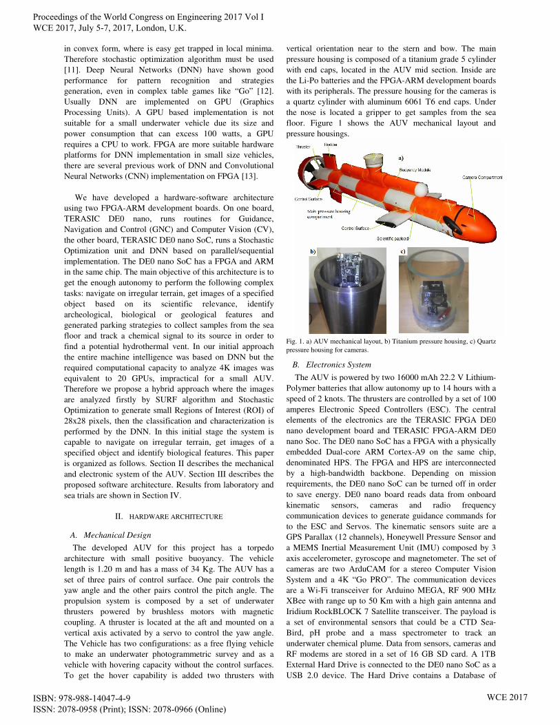
pressure housing is composed of a titanium grade 5 cylinder
with end caps, located in the AUV mid section. Inside are
the Li-Po batteries and the FPGA-ARM development boards
with its peripherals. The pressure housing for the cameras is
a quartz cylinder with aluminum 6061 T6 end caps. Under
the nose is located a gripper to get samples from the sea
floor. Figure 1 shows the AUV mechanical layout and
pressure housings.
Fig. 1. a) AUV mechanical layout, b) Titanium pressure housing, c) Quartz
pressure housing for cameras.
B. Electronics System
The AUV is powered by two 16000 mAh 22.2 V Lithium-
Polymer batteries that allow autonomy up to 14 hours with a
speed of 2 knots. The thrusters are controlled by a set of 100
amperes Electronic Speed Controllers (ESC). The central
elements of the electronics are the TERASIC FPGA DE0
nano development board and TERASIC FPGA-ARM DE0
nano Soc. The DE0 nano SoC has a FPGA with a physically
embedded Dual-core ARM Cortex-A9 on the same chip,
denominated HPS. The FPGA and HPS are interconnected
by a high-bandwidth backbone. Depending on mission
requirements, the DE0 nano SoC can be turned off in order
to save energy. DE0 nano board reads data from onboard
kinematic sensors, cameras and radio frequency
communication devices to generate guidance commands for
to the ESC and Servos. The kinematic sensors suite are a
GPS Parallax (12 channels), Honeywell Pressure Sensor and
a MEMS Inertial Measurement Unit (IMU) composed by 3
axis accelerometer, gyroscope and magnetometer. The set of
cameras are two ArduCAM for a stereo Computer Vision
System and a 4K “Go PRO”. The communication devices
are a Wi-Fi transceiver for Arduino MEGA, RF 900 MHz
XBee with range up to 50 Km with a high gain antenna and
Iridium RockBLOCK 7 Satellite transceiver. The payload is
a set of environmental sensors that could be a CTD Sea-
Bird, pH probe and a mass spectrometer to track an
underwater chemical plume. Data from sensors, cameras and
RF modems are stored in a set of 16 GB SD card. A 1TB
External Hard Drive is connected to the DE0 nano SoC as a
USB 2.0 device. The Hard Drive contains a Database of
Proceedings of the World Congress on Engineering 2017 Vol I WCE 2017, July 5-7, 2017, London, U.K.
ISBN: 978-988-14047-4-9 ISSN: 2078-0958 (Print); ISSN: 2078-0966 (Online)
WCE 2017

images, 3D models and DNN configurations. Figure 2 shows
the electronics Layout of the AUV.
Fig. 2. AUV Electronics Layout.
III. SOFTWARE ARCHITECTURE
The software architecture is divided in two components: an
Autopilot system and a Machine Intelligence in a client-
server configuration. The Autopilot runs on the DE0 nano
and the Machine Intelligence on the DE0 nano SoC. If the
AUV mission is a photogrammetric survey, the Machine
Intelligence could be turned off to save energy. The
Autopilot is divided in three layers. The low layer
implements communication protocol of sensors, SD card
write/read routines, RAM memory management and
generates PWM control signals for the ESC and Servos. The
mid layer contains the GNC and CV. The low layer and mid
layer are described by VHDL. The upper layer is the
Mission Manager. The Machine Intelligence is divided in
two components: a stochastic optimization unit and DNN.
The original idea contemplated 4K frames processing with
DNN, but the required computational resources, an
equivalent of 20 NVIDIA GeForce GPUs, are not suitable
for a small AUV due size and power limitations. In our
approach a preliminary image analysis is performed by the
SURF algorithm and stochastic optimization looking for
specific 3D shapes stored in the external Hard Drive,
examples: a jelly fish or a piece from a shipwreck. The result
of the analysis is a set of ROI with 28x28 pixels with 8 bit
gray scale. The DNN operates on these ROI looking for
specific features to classify and characterized the object of
interest. The Stochastic Optimization and DNN run on a
Linux Embedded System as an app in the HPS
complemented by a hardware accelerator described by
VHDL modules. Figure 3 shows the software architecture.
A. GNC and Mission Manager
The Baseline of the GNC is the Extended Kalman Filter
(EKF) to perform an Inertial Navigation System (INS). The
EKF fuses data captured from the IMU, GPS and Pressure
Sensor. Since the INS uses low cost IMU, input data
presents errors such as bias, scale factors, random walk
Fig. 3. Software Architecture
noise and temperature internal compensation. The EKF was
developed from a set of differential equations that describes
the vehicle’s dynamics and the noise process in order to
minimize the errors of the estimated state vector. The INS
estimates position, velocity and attitude of the AUV with an
inertial reference frame. The guidance law used is a fairly
simple algorithm called "Line of Sight" that generates the
reference yaw angle [14]. The mission manager provides the
list of flight path coordinates. The AUV automatic control
system is based on PID and Fuzzy Logic controllers, this
architecture allows a faster and precise response. The PID
controllers are implemented by the discrete equation type A
[15]. The mathematical operations are based on IEEE 754
64-bit floating point arithmetic. The trigonometric functions
are implemented by floating-point CORDIC algorithm [16].
The mathematical operations are based on ALTERA mega
functions for addition, multiplication and division, in the
worst case the latency is 10 clock cycles. The readings of the
onboard sensors are converted from fixed point to 64 bits
floating point, published by a tri-state buffer on a central bus
and then stored in a FPGA internal RAM formed by M9K
memory blocks. A state machine runs GNC opperations and
finally the results are converted from floating point to fixed
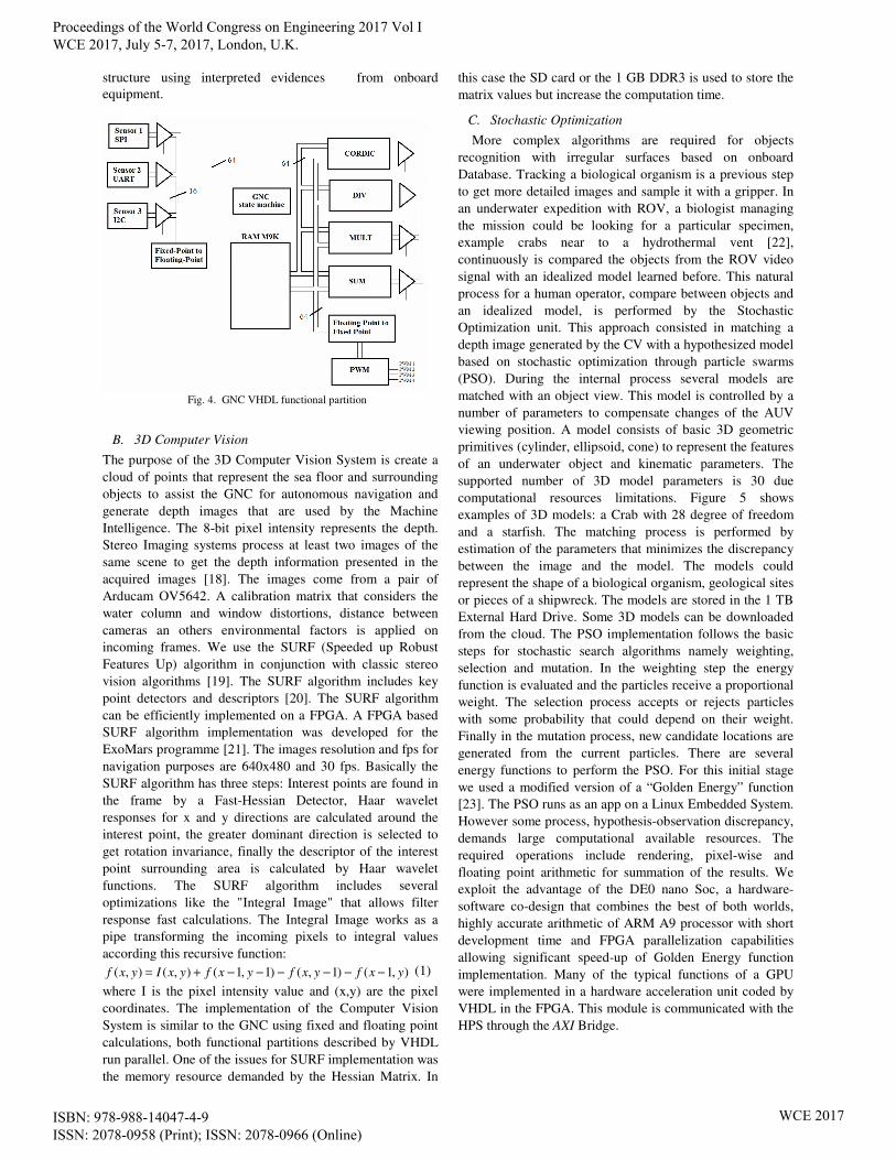
point. Figure 4 shows the VHDL functional partition of the
GNC. The Mission Manager is described with C language,
runs in a soft core 32 bits embedded processor Nios II. The
Nios II embedded processor is communicated with the
VHDL blocks through the Avalon bus. With the available
information from GNC, CV and RF communications the
Mission Manager, using Bayesian Networks, generates the
reference coordinates for the GNC. For mission
reconfiguration purposes the DNN are available for the
Mission Manager. The DNN will help to estimate a priori the
risk of vehicle loss during a mission. The Bayesian Networks
helps to perform an auto-test of all onboard equipment and
isolate spurious information from ill-equipment [17].
Isolation is performed by changing the Bayesian network
Proceedings of the World Congress on Engineering 2017 Vol I WCE 2017, July 5-7, 2017, London, U.K.
ISBN: 978-988-14047-4-9 ISSN: 2078-0958 (Print); ISSN: 2078-0966 (Online)
WCE 2017
structure using interpreted evidences from onboard
equipment.
Fig. 4. GNC VHDL functional partition
B. 3D Computer Vision
The purpose of the 3D Computer Vision System is create a
cloud of points that represent the sea floor and surrounding
objects to assist the GNC for autonomous navigation and
generate depth images that are used by the Machine
Intelligence. The 8-bit pixel intensity represents the depth.
Stereo Imaging systems process at least two images of the
same scene to get the depth information presented in the
acquired images [18]. The images come from a pair of
Arducam OV5642. A calibration matrix that considers the
water column and window distortions, distance between
cameras an others environmental factors is applied on
incoming frames. We use the SURF (Speeded up Robust
Features Up) algorithm in conjunction with classic stereo
vision algorithms [19]. The SURF algorithm includes key
point detectors and descriptors [20]. The SURF algorithm
can be efficiently implemented on a FPGA. A FPGA based
SURF algorithm implementation was developed for the
ExoMars programme [21]. The images resolution and fps for
navigation purposes are 640x480 and 30 fps. Basically the
SURF algorithm has three steps: Interest points are found in
the frame by a Fast-Hessian Detector, Haar wavelet
responses for x and y directions are calculated around the
interest point, the greater dominant direction is selected to
get rotation invariance, finally the descriptor of the interest
point surrounding area is calculated by Haar wavelet
functions. The SURF algorithm includes several
optimizations like the "Integral Image" that allows filter
response fast calculations. The Integral Image works as a
pipe transforming the incoming pixels to integral values
according this recursive function:
),1()1,()1,1(),(),( yxfyxfyxfyxIyxf −−−−−−+= (1)
where I is the pixel intensity value and (x,y) are the pixel
coordinates. The implementation of the Computer Vision
System is similar to the GNC using fixed and floating point
calculations, both functional partitions described by VHDL
run parallel. One of the issues for SURF implementation was
the memory resource demanded by the Hessian Matrix. In
this case the SD card or the 1 GB DDR3 is used to store the
matrix values but increase the computation time.
C. Stochastic Optimization
More complex algorithms are required for objects
recognition with irregular surfaces based on onboard
Database. Tracking a biological organism is a previous step
to get more detailed images and sample it with a gripper. In
an underwater expedition with ROV, a biologist managing
the mission could be looking for a particular specimen,
example crabs near to a hydrothermal vent [22],
continuously is compared the objects from the ROV video
signal with an idealized model learned before. This natural
process for a human operator, compare between objects and
an idealized model, is performed by the Stochastic
Optimization unit. This approach consisted in matching a
depth image generated by the CV with a hypothesized model
based on stochastic optimization through particle swarms
(PSO). During the internal process several models are
matched with an object view. This model is controlled by a
number of parameters to compensate changes of the AUV
viewing position. A model consists of basic 3D geometric
primitives (cylinder, ellipsoid, cone) to represent the features
of an underwater object and kinematic parameters. The
supported number of 3D model parameters is 30 due
computational resources limitations. Figure 5 shows
examples of 3D models: a Crab with 28 degree of freedom
and a starfish. The matching process is performed by
estimation of the parameters that minimizes the discrepancy
between the image and the model. The models could
represent the shape of a biological organism, geological sites
or pieces of a shipwreck. The models are stored in the 1 TB
External Hard Drive. Some 3D models can be downloaded
from the cloud. The PSO implementation follows the basic
steps for stochastic search algorithms namely weighting,
selection and mutation. In the weighting step the energy
function is evaluated and the particles receive a proportional
weight. The selection process accepts or rejects particles
with some probability that could depend on their weight.
Finally in the mutation process, new candidate locations are
generated from the current particles. There are several
energy functions to perform the PSO. For this initial stage
we used a modified version of a “Golden Energy” function
[23]. The PSO runs as an app on a Linux Embedded System.
However some process, hypothesis-observation discrepancy,
demands large computational available resources. The
required operations include rendering, pixel-wise and
floating point arithmetic for summation of the results. We
exploit the advantage of the DE0 nano Soc, a hardware-
software co-design that combines the best of both worlds,
highly accurate arithmetic of ARM A9 processor with short
development time and FPGA parallelization capabilities
allowing significant speed-up of Golden Energy function
implementation. Many of the typical functions of a GPU
were implemented in a hardware acceleration unit coded by
VHDL in the FPGA. This module is communicated with the
HPS through the AXI Bridge.
Proceedings of the World Congress on Engineering 2017 Vol I WCE 2017, July 5-7, 2017, London, U.K.
ISBN: 978-988-14047-4-9 ISSN: 2078-0958 (Print); ISSN: 2078-0966 (Online)
WCE 2017
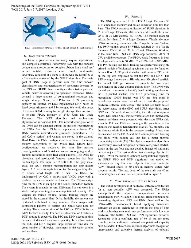
Fig. 5. Examples of 3D model for PSO a) crab model, b) starfish model
D. Deep Neural Networks
Achieve a great vehicle autonomy require sophisticate,
and complex algorithms. Performing PSO with the onboard
computational resources on complex objects like a coral reef
is not suitable. However some complex underwater
structures, coral reef or a piece of shipwreck are identified as
a “navigation obstacle” by the SURF algorithm. The main
goal of DNN usage is perform near real time onboard
classification and characterization of specimens detected by
the PSO and SURF, then reconfigure the mission path and
vehicle behavior according to specimen relevance. DNNs
demand a large amount of computational resources and
weight storage. Since the FPGA and HPS processing
capacity are limited, we have implemented DNN based on
fixed-point arithmetic and 3-bit weight. We avoid the usage
of external RAM memory for weight storage, they are stored
in on-chip FPGA memory of 2460 Kbits and Logic
Elements. The DNN algorithm and Architecture
Optimization is based on [24]. The network configuration of
the DNN can be changed during the mission reconfiguring
the FPGA from the HPS by an application software. The
DNN possible networks configurations (compiled VHDL
and C/C++ scripts) and weights are stored in the external
Hard Drive. A DNN configuration is dedicated for image
features recognition of the 28x28 ROI. Others DNN
configurations are dedicated for tasks like mission
reconfiguration or AUV risk estimation. An ongoing work is
features recognition from ROI color patterns. The DNN for
biological and geological features recognition has three
hidden layers. The input is a 28x28 ROI, 8 bit gray scale.
DNN for AUV mission reconfiguration has four hidden
layers. A fixed-point optimization for the weights is applied
to reduce word length into 3 bits. The DNNs are
implemented by C/C++ scripts and VHDL code with a
modular parallel-sequential architecture. The C/C++ scripts
runs on the HPS as an app in the Linux Embedded System.
The system is scalable, several DE0 nano Soc can work in a
stack configuration to get more computational capacity. The
weights are trained off-line, several training images are
stored in the external Hard Drive. Initially, the system was
evaluated with hand writing numbers. Then images with
geometrical patterns of starfish and corals were used for
training. The execution time of the PSO and DDN limits the
AUV forward velocity. For each displacement of 3 meters, a
DNN routine is executed. The PSO and DNN execution time
depends of detected specimens quantity. In shallow waters
the PSO and DNN requires large execution time due the
great number of biological specimens in the water column
and sea floor.
IV. RESULTS
The GNC system used 21 % of FPGA Logic Elements, 30
% of embedded memory and has an execution time less than
3 ms. The FPGA resource utilization of SURF algorithm is
55 % of Logic Elements, 70% of embedded multipliers and
90 % of 32 MB external SD RAM. The mission manager
utilized less than 15 % of Logic Elements. Clearly, the most
FPGA consuming resources is the Computer Vision System.
The PSO routines coded by VHDL required 24 % of Logic
Elements. DNN utilized 70 % of Logic Elements. Working
at the same time, PSO and DNN app consumes 90 % of
CPU available resources. The FPGA clock frequency in both
development boards is 50 MHz. The HPS clock is 925 MHz.
The PSO testing and DNN training was performed using 3D
printed models of biological specimens that can be found on
the sea floor. A 3D printed starfish with number “1” wrote
on the top was employed to test the PSO and DNN. The
PSO average frame rate is 5Hz with two 3D printed starfish.
The actual PSO performance is suitable for low speed
specimens in the water column and sea floor. The DNN were
trained and successfully identify hand writing numbers on
the 3D printed starfish. The DNN processing time for
recognizing 10000 images was 570 ms. Sea trials in
Ecuadorian waters were carried out to test the proposed
hardware-software architecture. The initial sea trials tested
the performance of the GNC and SURF algorithms. After
GNC and CV worked successfully, the other development
board, DE0 nano SoC, was activated at sea but immediately
thermal problems were presented with the main FPGA chip
when the PSO and DNN are running at the same time, in few
minutes was reached temperatures over 50 oC, probably due
the absence of air flow in the pressure housing. A heat sink
has installed on the FPGA and the titanium pressure housing
was filled with helium gas that has a better thermal
conductivity than air [25]. The object recognition algorithms
successfully avoided navigation hazards, recognized starfish,
corals on the sea floor and got detailed images of stationary
interest objects. The system didn’t track moving objects like
a fish. With the installed onboard computational capacity,
the SURF, PSO and DNN algorithms can applied on
stationary or very low speed objects, this issue limits the
AUV forward speed to 30 cm/s in shallow waters with
irregular terrain. The max depth of the sea trials was 40 m.
Laboratory test and sea trials are presented in Figure 6.
V. CONCLUSIONS AND FUTURE WORKS
The initial development of hardware-software architecture
for a man portable AUV was presented. The FPGA
accomplished the required computational resources
demanded by the GNC and CV routines. High computational
demanding algorithms, PSO and DNN, fitted well on the
FPGA-ARM development board applying hardware-
software co-design techniques to exploit the best of both
worlds achieving near real time performance with low cost
hardware. The SURF, PSO and DNN algorithms performs
acceptable with a confident rate of 95 % but for more
complex tasks additional onboard computational capacity
must be added. Future works includes algorithms recognition
improvement and extensive thermal analysis of onboard
Proceedings of the World Congress on Engineering 2017 Vol I WCE 2017, July 5-7, 2017, London, U.K.
ISBN: 978-988-14047-4-9 ISSN: 2078-0958 (Print); ISSN: 2078-0966 (Online)
WCE 2017

hardware in pressure housings with bad thermal conductivity
like ceramics to support hardware expansions for more
complex DNN.
Fig. 6. Results: a) Printing a starfish 3D model, b) PSO evaluation and
DNN training with 3D printed model, c) Sea Trials
REFERENCES
[1] Tamaki U. "Observation of Deep Seafloor by Autonomous Underwater Vehicle". Indian Journal of Geo-Marine Sciences, Vol.
42 (8), pp. 1028-1033, December 2013. [2] Fabri M-C., Bargain A., P. Briand P., Gebruk A., Fouquet Y.,
Morineaux M., Desbruyères D. "The hydrothermal vent community of a new deep-sea field, Ashadze-1, 12°58′ N on the Mid-Atlantic
Ridge". Journal of the Marine Biological Association of the United Kingdom, Vol. 91 (1): Pages 1-13. February 2011.
[3] Shell Ocean Discovery XPRIZE Home Page. oceandiscovery.xprize.org.
[4] Stokey R., Roup A., “Development of the REMUS 600 autonomous underwater vehicle”, OCEANS 2005 Proc. of MTS/IEEE, Vol.2 pp.
1301‐1304.
[5] L. Freitag, M. Grund, S. Singh, J. Partan, P. Koski, K. Ball, “The WHOI Micro-Modem: an acoustic communications and navigation
system for multiple platforms,” in Proc. Oceans 2005, Washington DC, 2005.
[6] Oceana: Protecting the World’s Oceans. http://oceana.org/. [7] C. Mcgann, F. Py, K. Rajan, H. Thomas, R. Henthorn, R. Mcewen,
"T-REX: A Model-Based Architecture for AUV Control". In Proceedings of the International Conference on Automated Planning & Scheduling, Rhode Island, USA, 2007.
[8] L. Stutters, H. Liu, C. Tiltman, D. Brown, “Navigation technologies
for autonomous underwater vehicles,” Systems, Man and Cybernetics, Part C: Applications and Reviews, IEEE Transactions on, vol. 38, no. 4, pp. 581 –589, Jul. 2008.
[9] Fossum T. O., "Intelligent Autonomous Underwater Vehicles: A
Review of AUV Autonomy and Data-Driven Sample Strategies". Norwegian University of Science and Technology. August 2016.
[10] N. Palomeras, S. Nagappa, D. Ribas, N. Gracias, M. Carreras, "Vision-based localization and mapping system for AUV
intervention". In OCEANS-Bergen, June 2013 MTS/IEEE (pp. 1-7). [11] A. Kuznetsova, G. Pons-Moll, B. Rosenhahn, "PCA-enhanced
stochastic optimization methods". In Joint DAGM (German Association for Pattern Recognition) and OAGM Symposium (pp.
377-386). Springer Berlin Heidelberg. August 2012. [12] Silver, D., Huang, A., Maddison, C. J., Guez, A., Sifre, L., Van Den
Driessche, G., ... & Dieleman, S. (2016). “Mastering the game of Go
with deep neural networks and tree search”. Nature, 529(7587), 484-489.
[13] Zhang, C., Li, P., Sun, G., Guan, Y., Xiao, B., & Cong, J. (2015, February). “Optimizing fpga-based accelerator design for deep
convolutional neural networks”. In Proceedings of the 2015 ACM/SIGDA International Symposium on Field-Programmable Gate Arrays (pp. 161-170). ACM.
[14] M. Caccia, “Preliminary sea trials of SESAMO: An autonomous surface vessel for the study of the air-sea interface,” CNR-ISSIA Sez. Di Genova, Tech. Rep. Rob-04-SESAMO pt, 2004.
[15] G. Szafranski, R. Czyba. "Different Approaches of PID Control UAV Type Quadrotor". Proceedings of the International Micro Air Vehicles conference 2011 summer edition
[16] N. Neji, A. Boudabous, W. Kharrat, N. Masmoudi. "Architecture and
FPGA implementation of the CORDIC algorithm for fingerprints recognition systems". 2011 8th International Multi-Conference on Systems, Signals and Devices (SSD).
[17] O. Mengshoel, A. Darwiche, S. Uckun. "Sensor validation using
Bayesian networks". In Proceedings of the 9th International Symposium on Artificial Intelligence, Robotics, and Automation in Space (iSAIRAS-08), 2008.
[18] C. Cuadrado, A. Zuloaga, J. Martin, J. Laizaro. "Real-Time Stereo
Vision Processing System in a FPGA". IECON 2006 - 32nd Annual Conference on IEEE Industrial Electronics.
[19] Moeslund, T. B., & Granum, E. (2001). “A survey of computer vision-based human motion capture”. Computer vision and image
understanding, 81(3), 231-268. [20] Battezzati, N., Colazzo, S., Maffione, M., & Senepa, L. (2012,
March). SURF algorithm in FPGA: “A novel architecture for high
demanding industrial applications”. In Design, Automation & Test in Europe Conference & Exhibition (DATE), 2012 (pp. 161-162). IEEE.
[21] Lentaris, G., Stamoulias, I., Diamantopoulos, D., Siozios, K., & Soudris, D. An FPGA implementation of the SURF algorithm for the
ExoMars programme. [22] Martinez, A. S., Toullec, J. Y., Shillito, B., Charmantier-Daures, M.,
& Charmantier, G. (2001). Hydromineral regulation in the hydrothermal vent crab Bythograea thermydron. The Biological
Bulletin, 201(2), 167-174. [23] T. Sharp, C. Keskin, D. Robertson, J. Taylor, J. Shotton, D. Kim, C.
Rhemann, I. Leichter, A. Vinnikov, Y. Wei, D. Freedman, P. Kohli, E. Krupka, A. Fitzgibbon, and S. Izadi. “Accurate, robust, and
flexible realtime hand tracking”. In Proc. CHI, pages 3633–3642, 2015.
[24] Park, J., & Sung, W. (2016, March). FPGA based implementation of deep neural networks using on-chip memory only. In Acoustics,
Speech and Signal Processing (ICASSP), 2016 IEEE International Conference on (pp. 1011-1015). IEEE.
[25] Burnett, J., Rack, F., Zook, B., & Schmidt, B. (2015, October). Development of a borehole deployable remotely operated vehicle for
investigation of sub-ice aquatic environments. In OCEANS'15 MTS/IEEE Washington (pp. 1-7). IEEE.
Proceedings of the World Congress on Engineering 2017 Vol I WCE 2017, July 5-7, 2017, London, U.K.
ISBN: 978-988-14047-4-9 ISSN: 2078-0958 (Print); ISSN: 2078-0966 (Online)
WCE 2017


![Stochastic Synthesizer Patch Exploration in Edisynsean/papers/evomusart19.pdfinto a commercial product (Nord’s Modular G2 synthesizer editor) [7–9]. MutaSynth is manual in operation:](https://img.pdfslide.us/doc/110x75/5e93d61045938d785949be60/stochastic-synthesizer-patch-exploration-in-edisyn-seanpapers-into-a-commercial.jpg)