Embed Size (px)
Citation preview
A MODEL TRANSFORMATION APPROACH FOR CODE
GENERATION FROM STATE MACHINE DIAGRAM
Brahim BOUSETTA. Lab. LAVETE, FSTS, Hassan 1st University, Settat Morocco.
Omar EL BEGGAR, Toufiq GADI. Lab. LAVETE, FSTS, Hassan 1st University, Settat Morocco.
{elbeggar_omar,gtaoufiq}@yahoo.fr
ABSTRACT
The Unified Modeling Language (UML) is widely considered as the defacto standard for the design of Object Oriented
systems. This is standard has been wildly improved by the Model Driven Architecture (MDA) an other inititive of OMG
to provide a complete development process for complex system. MDA promotes the use of models through the entire
development process starting from a CIM for requirement specification to code generation. MDA provides also a set of
model transformation to connect them and generate automatically the code. Among these models, UML state machines,
finite state machines constitute the most widely used to specify the dynamic behavior of a system. However, generating
code from state machine models, as part of the final system, constitutes one of the most challenging tasks due to its
dynamic nature and because many state machine concepts are not supported by the object-oriented programming
languages. Therefore, in this paper we introduce an approach to automatically generate code for specific platform from
state machine.
KEYWORDS
State machine, MDA, model transformation code generation.
1. INTRODUCTION
In software engineering the UML (Object Management Group (OMG), 2004) is nowadays the lingua franca
for object-oriented modeling. Development of systems with such modeling language is based principally on
models as abstractions of real-world and/or thought concepts where different kinds of models represent
different views on a system. During systems development such models are enriched with additional
information and are thus transformed from more abstract into more concrete ones. While object oriented
models traditionally served as blueprints for manual systems implementation, the model driven architecture
initiative of the OMG (OMG, 2003) promotes the usage of models throughout the entire development
process. Starting from a so-called Computation Independent Model (CIM), different kinds of transformations
lead to Platform Specific Models (PSMs). These PSMs can be used later to generate code for a specific
platform.
In this sense, this paper provides an approach to automate the generation of a basic behavior specification
for the system modeled in the UML State machine. This improves the productivity and quality of the
designers’ job since writing a behavior specification is a very time-consuming and error-prone task. Although
our method can be useful in any application domain, our method is especially useful for domains where there
is classes that knows a excessive change of state more than interactions. The basic behavior specification
generated by our method consists in a set of well-formed set of operations that suffice to cover most of the
IADIS International Journal on Computer Science and Information Systems Vol. 9, No. 1, pp. 1-15 ISSN: 1646-3692
1
required system’s behavior. More specifically, the generated operations allow designers to perform all
required operation defined in life cycle of the class represented I state machine diagram. The number and
effect of the operations are determined based on the domain knowledge contained in the dynamic view of the
State machine diagram.
The presented approach in this paper is a code generation by model transformation approach taking as
source models: the Domain Class Diagram (DCD) which is gives a static view of the system and the
Transition’s State Diagram (TSD) which defines a machine that has a number of states (hence the term finite
state machine) that receives events from the outside world, and each event can cause the machine to
transition from one state to another. Instead of generating directly plain text for the chosen platform, an
intermediate structural model for the Java platform is generated. Such intermediate model will enable its
extensibility with new features. The core idea of this article is code generation by model transformation from
State transition diagram for system complex classes. The generated code contains full details for the classes
(attributes) and full methods signatures.
The platform used in this paper is JAVA. However we will generate a structural model for the suited
platform instead generating directly the code, i.e. we will first generate a platform specific model (PSM)
form the PIMs DCD and TSD by the mean of a model-to-model transformation before generating the code
from this PSM by a model to code transformation. To perform these transformations we will use ATL [13,
14] which is a domain-specific language for specifying model-to-model transformations. It is inspired by the
OMG QVT requirements [12] and builds upon the OCL formalism [17].
The work reported here extends our previous work [24] in several directions. First, now we generate the
full operation’s specification including body with the implemented code. In fact, almost of the activities
executes when the object receives an event to change state induces an operation to change an attribute or to
create/destruct an object or doing some computing. Hence, we can generate the body’s implementation for
the almost operations. Second, we have profiled the generated structured model of JAVA platform with EJB
profile. Thereby, we can generate operations that allow designers to perform all required life-cycle change
events (create/delete/update/retrieve) on the population/value of the different model elements of the class
diagram.
The reminder of the paper is structured as follows. Section 2 gives an overview on the proposed approach
for the code generation from state machine diagram. The next section introduces concepts and principles of
the model driven engineering approach. Section 4 presents some relevant related works concerning the topic
of the present work. Then section 5 introduces the input models of this transformation and their metamodels
(metamodel of state machine diagram and the domain class diagram metamodel). The next section is devoted
to present the target Java platform metamodel. When the following section is dedicated to present the model
transformation and the main mapping rules that are used to generate the structured model for the target
platform and applying then the EJB profile to generate complete code. In the end, we conclude this work with
few prospects. An example of transformation is given to illustrate the approach presented in this paper using
the Eclipse’s ECORE metamodel.
2. APPROACH OVERVIEW
This paper presents a code generation approach by model transformation taking as source models: the
Domain Class Diagram (DCD) and State machine Diagram (SMD) and instead of generating directly plain
text for the chosen platform, an intermediate structural model for the Java platform is generated. Such
intermediate model will enable its extensibility with new features. The core idea of this article is code
generation by model transformation from transition State diagram for system’s complex classes. The
generated code contains full details for the class (attributes) and full methods signatures.
The approach allows the generation of full operations specification deduced from the system’s dynamic
represented in state machine diagram. Furthermore, we generate additionally necessary operations to manage
complete life cycle change of data (CRUD) based on applying the EJB profile to the generated structural
model of the target java platform.
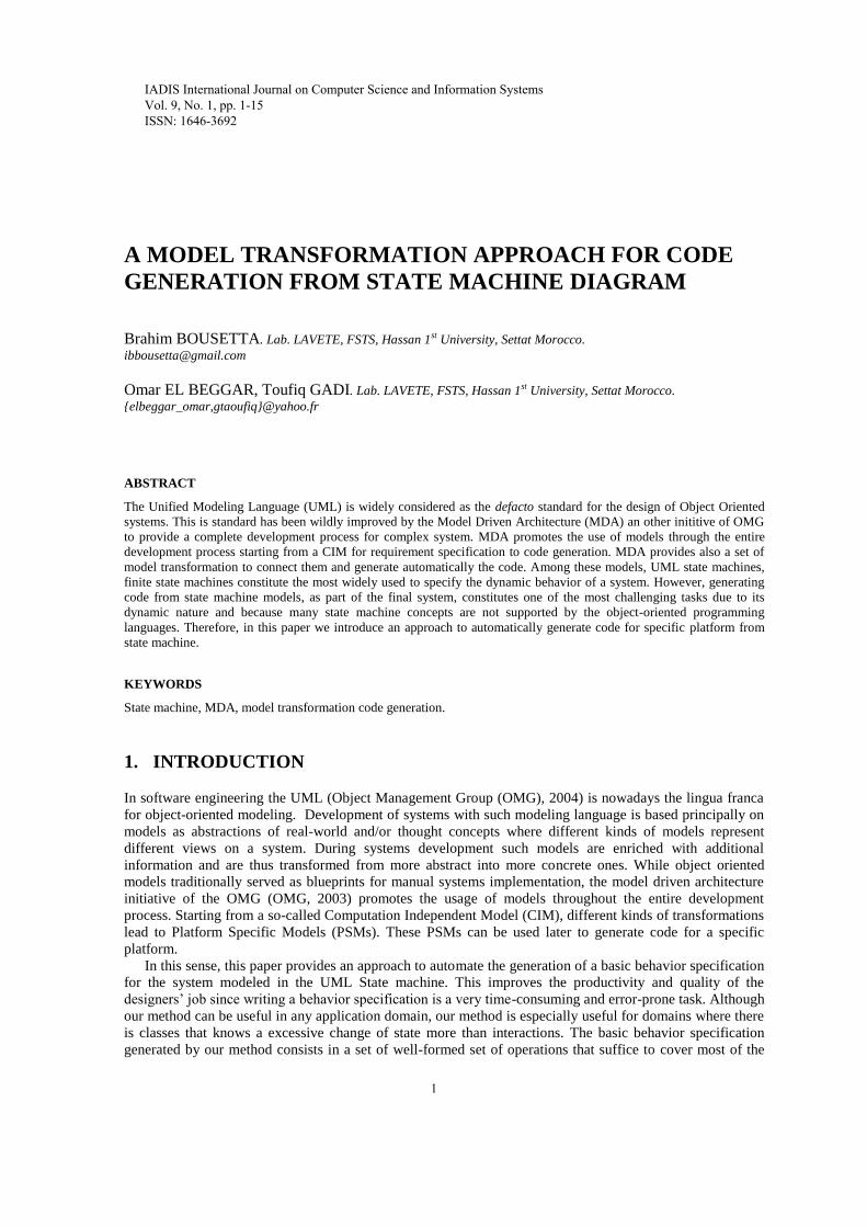
Our method can be split up into three main steps (Fig. 1):
Identification of operations from the activities executed upon receiving different events.
2
Specification of the operation signatures. The signature of each operation is derived from the
actions and events received by the object. Upon receiving an event the object changes the state
and performs an activity. The event contains necessary parameters to execute correctly this
activity. Hence, we can deduce the full operation signature correctly.
Generating structured model for java platform. The approach uses a structural model for the
target platform instead of generating directly the plain text to enable its extension after
generation with additional features.
Applying the EJB profile. To extend the java platform with EJB3 capabilities, we apply an EJB
profile to the generated structural model allowing thus to annotate the classes with necessary
information for the relational mapping of the entity to guaranty the generation of the basic
operation to manage data (CRUD).
Generating the code. The last step is generating the code from the structured model. We generate
the full classes with the full signature of operations and complete methods with full body
implementation of CRUD operations.
Figure 1: Overall view of the method.
3. MODEL DRIVEN ENGINEERING: PRINCIPLES
Model-driven approaches deal with the provision of models, transformations between them and code
generators to address software development. This approach has the advantage of defining a conceptual
structure, where the models used by business managers and analysts can be mapped into more detailed
models used by software developers. Generally, in software engineering development, these models are
expressed with the Unified Modeling Language UML [3, 4] (Object Management Group (OMG) [2]). The
model driven architecture (MDA) initiative of the OMG [1] promotes the usage of models throughout the
entire development process. Starting from a so-called Computation Independent Model (CIM), different
kinds of transformations lead to Platform Specific Models (PSMs). These PSMs can be used later to generate
code for a specific platform.
Model-Driven Development (MDD) comes with a new change in software development paradigm. In
fact, the scientific community has spent several years studying this paradigm change, through which software
development is guided by the idea of ‘everything is a model’, rather than ‘everything is an object’ [6]. This
discipline (also known as Model Driven Engineering – MDE) therefore considers models as being the most
important element for software development, maintenance and evolution through model transformation [7].
MDA [1] is an instance of MDE developed by OMG [2], and its objectives include separation from
business neutral descriptions and platform-dependent implementations, modeling specific aspects of a system
under development with specialized domain-specific languages, the establishment of precise relations
between these different languages in a global framework and, in particular, the ability to express operational
Domain class
Diagram
State machine
Diagram
Input models
Operations identification
Specification of operation’s
signature
Generating structural model
Applying EJB profile
Generating code
Public class Entity{
private int ref;
….
public void
setStatus(..){..}
public void create(){}
public update(){}
public Entity
retrieve(id){}
public void delete(){}
Output
3
transformations between them [6]. As a consequence, MDA provides portability, productivity,
interoperability and reusability by means of the architectural separation of concerns and throughout the
complete development lifecycle, covering analysis and design, programming, testing and component
assembly, along with coding and maintenance [8, 9].
The MDA approach defines models at three different levels of abstraction [10]: The computation
independent viewpoint (represented by the CIM) which focuses on the environment of the system and is
usually built by business analysts; the platform independent viewpoint (represented by the PIM) which is
built by system analysts and software architects and focuses on the operation of a system while hiding the
details necessary for a particular platform; and the platform specific viewpoint (represented by the PSM)
which combines the platform independent viewpoint with an additional focus on the details of using a
specific platform by a system [1]. In the context of MDA, Query/View/Transformation (QVT) [11,12] can be
considered as the standard model transformation language proposed by the OMG. Another model’s
transformation language that is based on OCL and has become increasingly used is the Atlas Transformation
Language (ATL [13, 14, 15, 16]).
Furthermore, MDA is based on UML that can be specialized or extended to express the required detailed
models. This extension or specialization of UML can be performed by using the UML Profile, a standardized
set of extensions (consisting of stereotypes and tagged values) defines a UML environment tailored to a
particular use, such as modeling in a specific environment or on a specific platform. PIMs will be modeled
using the profile for Enterprise Distributed Object Computing (EDOC) or Enterprise Application Integration
(EAI), both near the end of their successful adoption processes. The UML profile for CORBA completed
adoption by OMG in 2000; profiles for other platforms are in process.
We have chosen to use the Meta Object Facility of the OMG [5] as the metametamodel. It is used in many
OMG standards, most prominently as the metametamodel for the UML [4]. MOF is closely tied to UML; in
fact there are a number of packages called the UML Infrastructure [3] that are shared between MOF and
UML. MOF, however, is more than just a metametamodel. As the name suggests, it provides a metadata
management framework.
4. RELATED WORKS
Various works in the field of code generation domain have been led during the last few years, and these
works are interesting in the context of the present paper, those with high relevance will be highlighted in this
section.
The first Kind of code generator is based on code generation from Petri-Nets which has a long tradition.
However, unlike methods for the analysis and simulation of Petri-Nets, code generation is not yet considered
a standard feature. An extensive review of existing work in the area of automatic code generation from Petri-
Nets is given in [18]. Most of the approaches in this review focus on code generation from (extended) low-
level Petri-Nets, e.g. for the generation of controllers [19, 20]. Even though the review also lists approaches
for code generation from high-level Petri- Nets, the work in this area is not based on object-oriented
principles, and in consequence not applicable to more complex systems. A frequent use of approaches to
automatic code generation from Petri-Nets is the validation of requirements in systems engineering.
The second kind of code generator is generation of code by model transformation. These approaches treat
code as a model, while most MDE approaches generate code through the use of textual template engines,
which produce plain text, not amenable to further transformation. By treating generated code as a model, it is
possible to extend the target language and add convenient language features such as partial classes and
methods.
In [21] an approach for simplifying the specification of conceptual schemas (CSs) was presented. It
provides a way for modeling the operations that define the system behavior by providing a method that
automatically generates a set of basic operations that complement the static aspects of the CS and suffice to
perform create/update/delete operations. This method takes as input a CS expressed as a UML class diagram
and generates an extended version of the CS that includes all necessary operations to start operating the
system. While [21] provide a method for generating CRUD operations to manipulate database data, [22]
provides a tool for behavioral modeling. It defined textual and visual notations for UML actions and built
supporting editors. Further, it defined also a mapping from UML actions to Java and model compilers were
4
built, which support the generation of complete and compile-ready applications including their behavioral
parts.
This paper subscribes in the second categories of code generators which bases on code generation by
model transformation. We have also generated a structural model for the target platform to enable its
extensibility. Although that there is this variety of approaches for code generation, so far there is nowadays,
to our best knowledge, no tool for generating some code from transition state diagrams. Approaches based on
Petri nets are still far to be a standard for code generation and still not yet used in the different phases of
modeling, usually used for validation purposes. The motivation of this work is generating methods signature
for systems where there is complex classes that have multitudes states with a many transitions. In such
systems, these complex classes change their state intensively more than interacting with other objects;
thereby resulting operations from transition state diagram are more important than operations resulting from
interaction diagram like sequence diagram of system’s internal behavior, communication diagram.
This paper subscribes in global approach that aims to automate the software engineering process by
covering all the phases of the development starting from the requirement specification to code
implementation. In [25] we presented a software engineering process based on UML for leading an IT project
by specifying new artifacts and practices. We have introduced the model driven engineering approach and
our proposed MDA approach to automate the software development process with different possible
metamodels and transformation for the mapping between them. However, that paper focuses only on
generating one of the most important PIMs increments of the analysis phase, the Sequence diagram of
system’s internal behavior by a model transformation from the external one. This PIM is then used in [26] to
generate automatically the code for a specific platform by a model to text transformation. In that paper a
structured PSM model for the java platform was automatically generated. Finally, an executable
implementation of the system for the JAVA platform was generated. The work presented in [27] concerns the
phase of requirement specification. We have proposed an architecture for the CIM and PIM levels that allows
describing both dynamic and static view of the system. We have provided a model transformation to generate
the PIM models semi-automatically from these of the CIM level.
The present paper completes our previous works for the automation of the entire proposed software
development process by allowing generating the operation of complex classes through their state machine
diagram. This approach is especially efficient when modeling systems with classes that know an excessive
change of their state more than interacting with other objects like soda machine distributor, cashier, some
robots…
5. INPUT METAMODELS:
5.1. State machine diagram’s metamodel:
State machine diagrams have been used right from the beginning in object-oriented modeling. The basic idea
is to define a machine that has a number of states (hence the term finite state machine) which define a set of
values to attributes of the object at any given time. The machine receives events from the outside world, and
each event can cause the machine to transition from one state to another. Thus this machine represents the
class’s life cycle which is essential for representing and shaping the dynamics of the system and giving a
formal definition of system’s behavior.
Moreover, it is recommended to trace state diagram only for complex classes that have states excessively
variables and are often coveted by other classes. In this case, it is appropriate to create a state diagram of
these classes in order to limit the state transitions for a class compared to its interactions with other ones.
Finally analyze its "unstable" behavior improves our understanding of the problem and implements the
class’s methods. So the state diagrams allow us to complete the design class diagrams with methods that
correspond to different actions and activities of the state diagram.
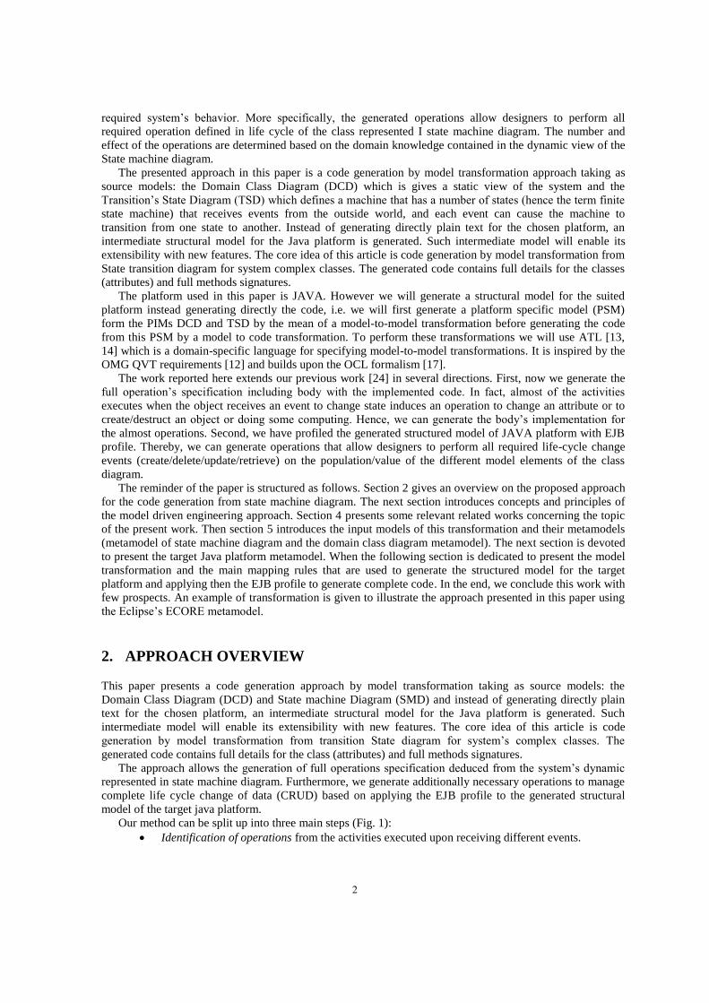
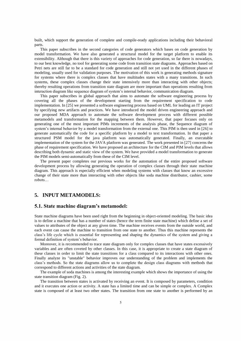
The example of soda machines is among the interesting example which shows the importance of using the
state transition diagram (Fig. 2).
The transition between states is activated by receiving an event. It is composed by parameters, condition
and it executes one action or activity. A state has a limited time and can be simple or complex. A Complex
state is composed of at least two other states. The transition from one state to another is performed by an
5
external event. A class can also have an internal transition without change of state trigged by an internal
event. The internal events are predefined (entry, do, on event after and exit). Event performs actions or
activities that are transformed into operations or class methods.
Figure 2: soda machine’s state machine diagram
In some cases, computer systems have more operations outcomes from events rather than operations
outcomes from the interaction between objects. In this case, transition states diagrams are best placed to find
these operations than other interaction diagrams (collaboration diagram, sequence diagram of internal
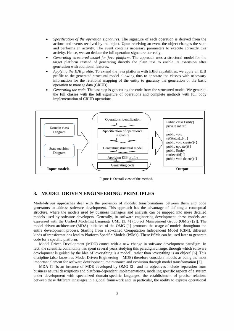
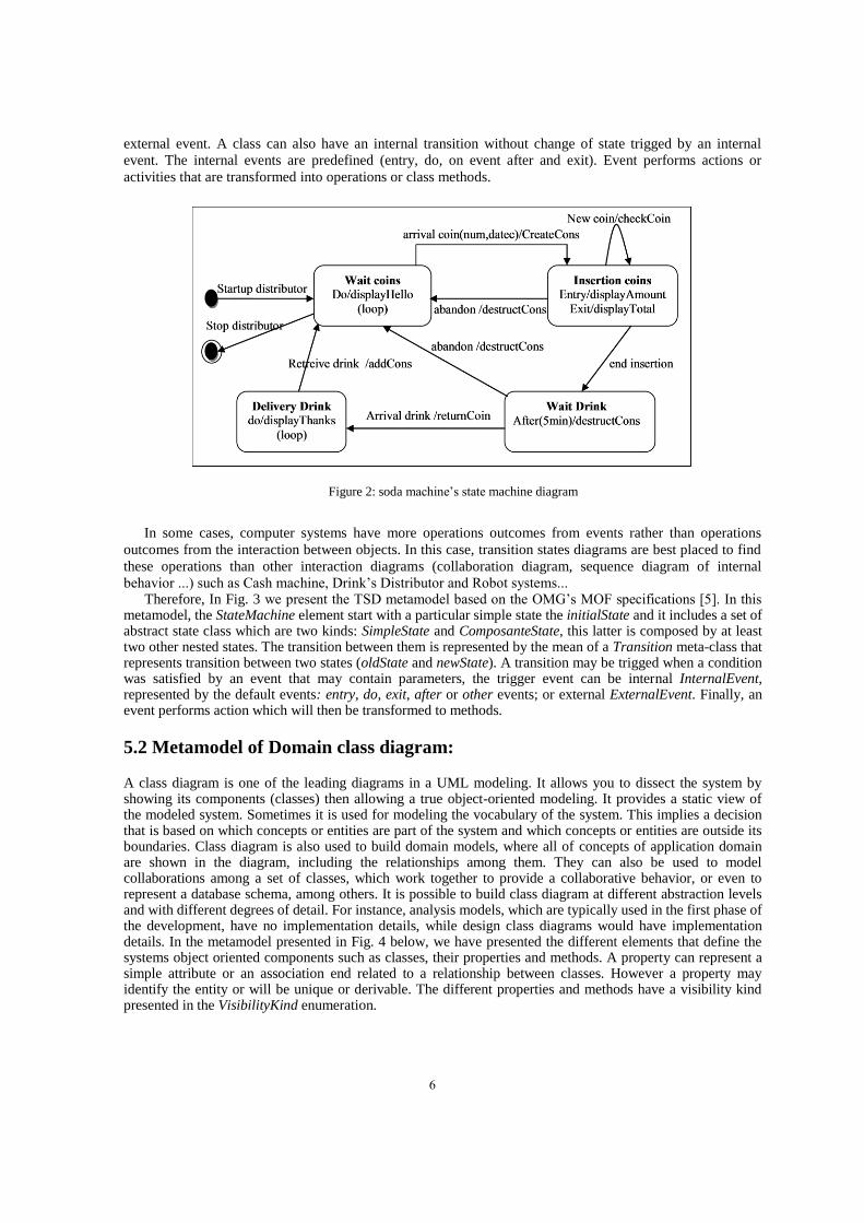
behavior ...) such as Cash machine, Drink’s Distributor and Robot systems... Therefore, In Fig. 3 we present the TSD metamodel based on the OMG’s MOF specifications [5]. In this
metamodel, the StateMachine element start with a particular simple state the initialState and it includes a set of abstract state class which are two kinds: SimpleState and ComposanteState, this latter is composed by at least two other nested states. The transition between them is represented by the mean of a Transition meta-class that represents transition between two states (oldState and newState). A transition may be trigged when a condition was satisfied by an event that may contain parameters, the trigger event can be internal InternalEvent, represented by the default events: entry, do, exit, after or other events; or external ExternalEvent. Finally, an event performs action which will then be transformed to methods.
5.2 Metamodel of Domain class diagram:
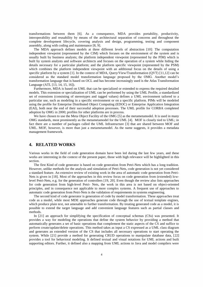
A class diagram is one of the leading diagrams in a UML modeling. It allows you to dissect the system by showing its components (classes) then allowing a true object-oriented modeling. It provides a static view of the modeled system. Sometimes it is used for modeling the vocabulary of the system. This implies a decision that is based on which concepts or entities are part of the system and which concepts or entities are outside its boundaries. Class diagram is also used to build domain models, where all of concepts of application domain are shown in the diagram, including the relationships among them. They can also be used to model collaborations among a set of classes, which work together to provide a collaborative behavior, or even to represent a database schema, among others. It is possible to build class diagram at different abstraction levels and with different degrees of detail. For instance, analysis models, which are typically used in the first phase of the development, have no implementation details, while design class diagrams would have implementation details. In the metamodel presented in Fig. 4 below, we have presented the different elements that define the systems object oriented components such as classes, their properties and methods. A property can represent a simple attribute or an association end related to a relationship between classes. However a property may identify the entity or will be unique or derivable. The different properties and methods have a visibility kind presented in the VisibilityKind enumeration.
6
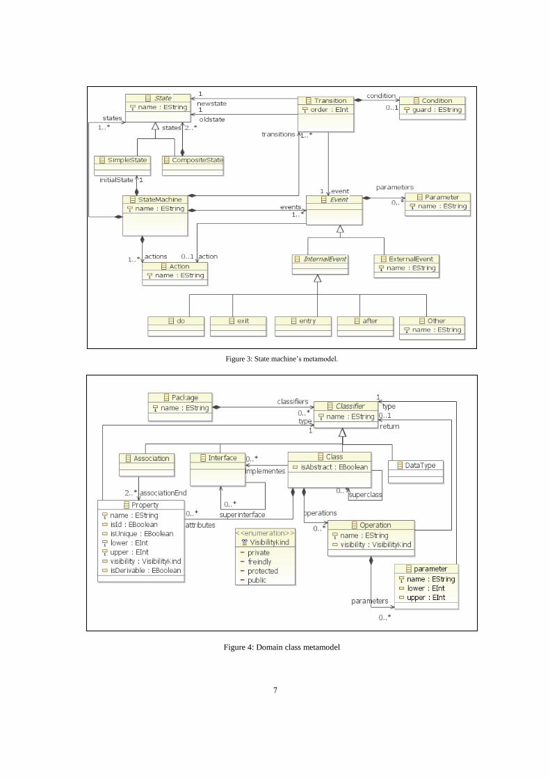
Figure 3: State machine’s metamodel.
Figure 4: Domain class metamodel
7
6. CODE GENERATION BY MODEL TRANSFORMATION
6.1 Model transformations: a general overview
Models are representations of a piece of the real world, and it is therefore very important to determine
whether a model is correct or not. Metamodels are the mechanism used to create correct models in order to
model a system. A metamodel ‘‘is an abstract language for some kind of metadata” [11]. So, a precise
metamodel is a prerequisite for performing automated model transformations.
According to the MDA standard, a model transformation is the process of converting one model into
another model from the same system, and it is considered to be a central part of MDE/MDD. Model
transformations are composed of fine- grained rules that transform elements defined in a specific source
metamodel into other elements of the target metamodel. They are defined at the metamodel level; the set of
rules and constraints refers to elements of the metamodels. Transformations are specified with suitable languages which are intended to deal with models. Thus, a
model transformation language is a language that: (i) take a model as input and (ii) according to a set of rules, and (iii) produces an output model. It is currently possible to find many model transformation languages such as ATL [13, 14, 15, 16] and QVT [11]. ATL is based on the main idea that the models are first-class entities. Therefore, and since everything is model, the transformations are also considered models. We can therefore apply their transformations, and it is one of the other important points about ATL.
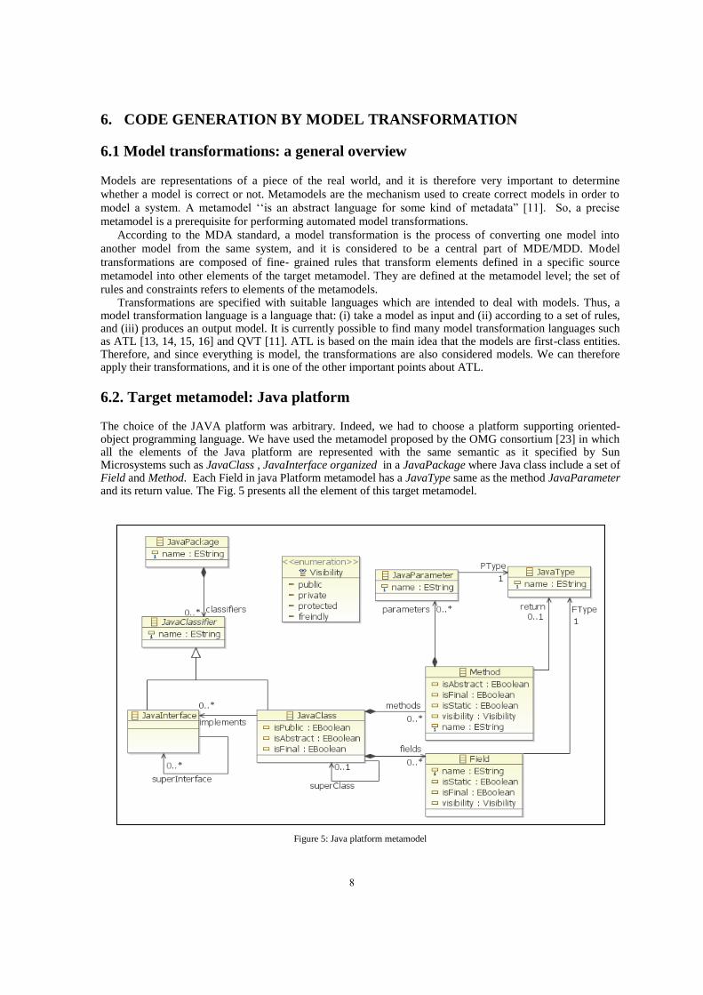
6.2. Target metamodel: Java platform
The choice of the JAVA platform was arbitrary. Indeed, we had to choose a platform supporting oriented-object programming language. We have used the metamodel proposed by the OMG consortium [23] in which all the elements of the Java platform are represented with the same semantic as it specified by Sun Microsystems such as JavaClass , JavaInterface organized in a JavaPackage where Java class include a set of Field and Method. Each Field in java Platform metamodel has a JavaType same as the method JavaParameter and its return value. The Fig. 5 presents all the element of this target metamodel.
Figure 5: Java platform metamodel
8
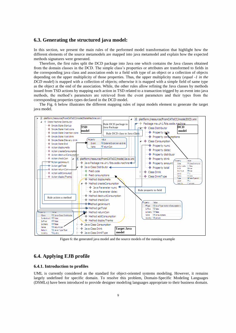
6.3. Generating the structured java model:
In this section, we present the main rules of the performed model transformation that highlight how the
different elements of the source metamodels are mapped into java metamodel and explain how the expected
methods signatures were generated.
Therefore, the first rules split the DCD package into Java one which contains the Java classes obtained
from the domain classes in the DCD. The simple class’s properties or attributes are transformed to fields in
the corresponding java class and association ends to a field with type of an object or a collection of objects
depending on the upper multiplicity of those properties. Thus, the upper multiplicity many (equal -1 in the
DCD model) is mapped with a collection of objects; otherwise it is mapped with a simple field of same type
as the object at the end of the association. While, the other rules allow refining the Java classes by methods
issued from TSD actions by mapping each action in TSD related to a transaction trigged by an event into java
methods, the method’s parameters are retrieved from the event parameters and their types from the
corresponding properties types declared in the DCD model.
The Fig. 6 below illustrates the different mapping rules of input models element to generate the target
java model.
6.4. Applying EJB profile
6.4.1. Introduction to profiles
UML is currently considered as the standard for object-oriented systems modeling. However, it remains
largely undefined for specific domain. To resolve this problem, Domain-Specific Modeling Languages
(DSMLs) have been introduced to provide designer modeling languages appropriate to their business domain.
Rule action to method
Target Java
model
DCD
model
TSD
model
Rule DCD package to
Java Package
Rule DCD class to Java class
Rule property to field
Figure 6: the generated java model and the source models of the running example
9
However, DSMLs should continuously evolve to adapt to the changing needs of the domain they represent.
Changing the metamodel is a very costly process that requires changing its metamodel and possible re-
creating the complete modeling environment.
UML has avoided these problems by promoting the use of profiles that provide a lightweight, language-
inherent extension mechanism to the UML by defining custom stereotypes, tagged values, and constraints.
Profiles allow for adaptation of the UML metamodel for different platforms (such as J2EE or .NET), or
domains (such as real-time or business process modeling) [5]. The profiles mechanism is not a first-class
extension mechanism. It does not allow to modify existing metamodels or to create a new metamodel as
MOF does. Profile only allows adaptation or customization of an existing metamodel with constructs that are
specific to a particular domain, platform, or method. It is not possible to take away any of the constraints that
apply to a metamodel, but it is possible to add new constraints that are specific to the profile. Metamodel
customizations are defined in a profile, which is then applied to a package. Stereotypes are specific
metaclasses, tagged values are standard metaattributes, and profiles are specific kinds of packages.
One of the major advantages of UML Profiles is the ability to systematically introduce further language
elements without having to re-create the whole modeling environment such as editors, transformations, and
model APIs. In contrast to direct metamodel extensions, also already existing models may be dynamically
extended by additional profile information without recreating the extended model elements. One model
element may further be annotated with several stereotypes (even contained in different profiles) at the same
time which is equivalent to the model element having multiple types. Furthermore, the additional information
introduced by the profile application is kept separated from the model and, therefore, does not pollute the
actual model instances.
6.4.2. EMF profiles
Since UML profile is located at the same level of abstraction as UML itself, it can only used to extend UML
models. In this paper we use the EMF platform that uses the ECORE metametalanguage to create different
metamodels, therefore we cannot use UML profiles to extend our DSML, hence the need to use EMF profile
[28]. Also, the model transformation language ATL used in this proposal does not support UML model, only
models based on Ecore metamodel can be used as a source models of the transformation.
The main objective of applying profiles in this paper is to show how the generated structural model of the
performed transformation can be extended with new features before generating the implementation code. As
an example we have applied the EJB3 profile [29, 30] that is presented in the next section. The use of profiles
has many advantages like the ability of annotating model slightly as possible; hence, no adaptation of
existing metamodels should be required. Also, It avoids polluting existing metamodels with concerns not
directly related to the modeling domain separating annotations from the base model to allow importing only
those annotations which are of current interest for a particular modeler in a particular situation.
To incorporate the profile mechanism into EMF, a language for specifying profiles is needed as a first
ingredient. This is easily achieved by creating an Ecore-based metamodel which is referred to as Profile
MetaModel that will be instantiated to create a specific profile, containing stereotypes and tagged values.
Once a specific profile is at hand, users should now be enabled to apply this profile to arbitrary models by
creating stereotype applications containing concrete values for tagged values defined in the stereotypes [5].
6.4.3. EJB3 profile
Here we provide an example for extending the generated java model of the performed transformation by
applying the EJB 3 profile [29, 30, 31] established based on EMF profiles. Thus, we can generate an
additionally source code like CRUD operation allowing persistence by the mean of the EJB entities and the
EJB sessions.
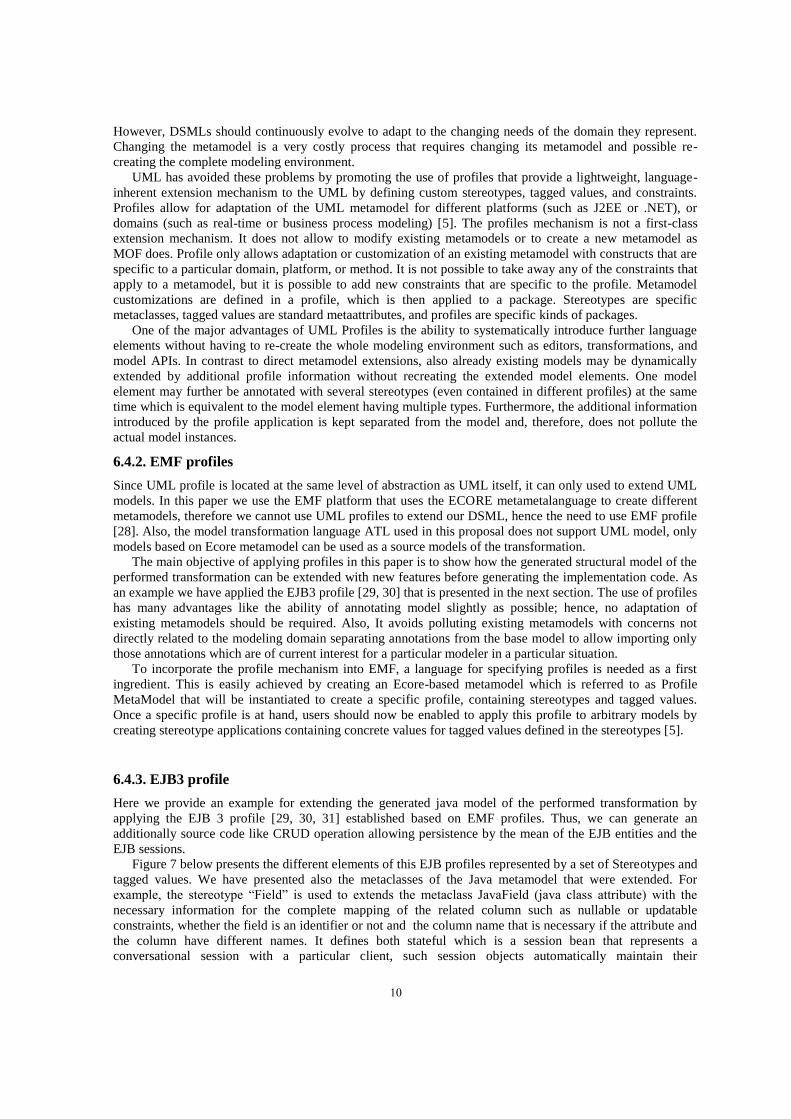
Figure 7 below presents the different elements of this EJB profiles represented by a set of Stereotypes and
tagged values. We have presented also the metaclasses of the Java metamodel that were extended. For
example, the stereotype “Field” is used to extends the metaclass JavaField (java class attribute) with the
necessary information for the complete mapping of the related column such as nullable or updatable
constraints, whether the field is an identifier or not and the column name that is necessary if the attribute and
the column have different names. It defines both stateful which is a session bean that represents a
conversational session with a particular client, such session objects automatically maintain their
10
conversational state across multiple client-invoked methods, and stateless session beans that represent an EJB
Bean without state for a client that will invoke only one method. The client of a session bean may be a local
client, a remote client or a web service client depending on the interface provided by the bean and used by
the client. An entity object represents a fine-grained persistent object. The client of an entity bean may be a
local client or the client may be a remote client. An EJB Method is declared by a Java Method declaration
within an EJB Home or Remote Interface. The EJB Method is an EJB Home Method, if declared within an
EJB Home Interface, or an EJB Remote Method, if declared within an EJB Remote Interface. The declaration
of an EJB Remote Interface extends the declaration of a Java Interface with EJB Deployment Descriptor
elements for an EJB Enterprise Bean. The name of the EJB Remote Interface and the related EJB Home
Interface are specified by remote and home elements in the entity or session element for the EJB Enterprise
Bean.
Figure 7: The EJB profile with the different extended metaclasses
6.5 Generating code
To generate code from the structured java model a rest of rules are defined to describe how to generate a java
code that creates the classes with their fields and methods organized in a java package relative to that existing
ones in the target model as it illustrated in Fig.8. Fig.6 shows some transformation rules to map the different
elements of the input metamodels to the target one. To generate this code we used the ATL query which is an
OCL expression that allows specifying requests onto. Thus, the query “generateCode()” used in the
proposal allowed us to navigate across the java model elements and generate automaticly the package that
contains the java classes, their fields and methods signatures. In order to perform the code generation other
ATL helpers are employed to accomplish the transformation such as “getParameters()” and
“getSignature()”.
Finally we focus on the specification of the methods signatures which depends on the actions included in
the TSD. Some events related to those actions may require the addition of new parameters to trigger the
The Java
metamodel
The EJB Profile
11
transition state. Therefore, every variable that appears as a parameter in the event must also appear as a
parameter in the method such as the numc and datec parameters of the createConsumption() method.
Note that the int and Date types of those parameters are deduced from the matched DCD attributes. The
code generated supports also the importation of the libraries such as the java.util necessary to employ the
Collection and the type date in the generated code by checking if there any fields in java model. Regarding
the method’s visibility, we have chosen to make the visibility public for getting and displaying methods and
private otherwise. Some return types of methods are also deduced from DCD since they are relatives to
objects or properties existing in the DCD.
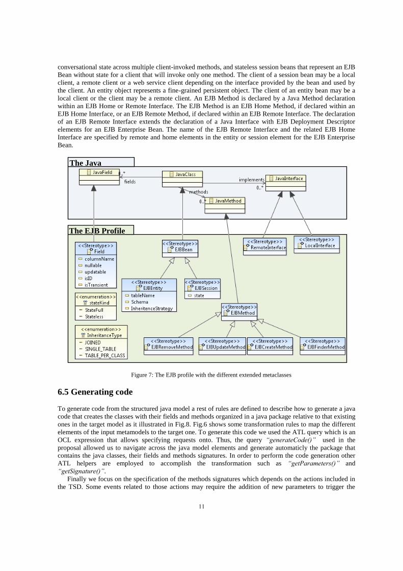
The second transformation performed in this paper is a model-to-code transformation that will allow for
transforming the generated structural model of the java model which has been enriched by applying the EJB
profile, the code source according to the JAVA platform. Thus, for each Java class a java file will be
generated containing the source code of the class including their methods (signature and body) and EJB
annotation for the JAVA class that are stereotyped with “EJBEntity”. Moreover, for each persistent class, a
Stateless EJBSessionbean and its corresponding Remote or Home interface will be generated implementing
the detailed source code of CRUD operation for data manipulation as well as the configuration file for
persistence “persistence.xml”. These operation are : save() which perform an initial save of a previously
unsaved EntityClass entity; delete() to delete a persistent EntityClass entity; update() which allows to
persist a previously saved EntityClass entity and return it or a copy of it to the sender, a copy of the
EntityClass entity parameter is returned when the JPA persistence mechanism has not previously been
tracking the updated entity; the findById() allowing the retrieve an EntityClass by identifier and the findAll
to retrieve all instance of this EntityClass.
For example for a persistent Entity Class EntityClass the following stateless bean and Interface will be
generated to support all the operations necessary to manage the whole life-cycle of data:
The generated java classes and
methods signatures
The Created Package
Figure 8: The generated java project
12
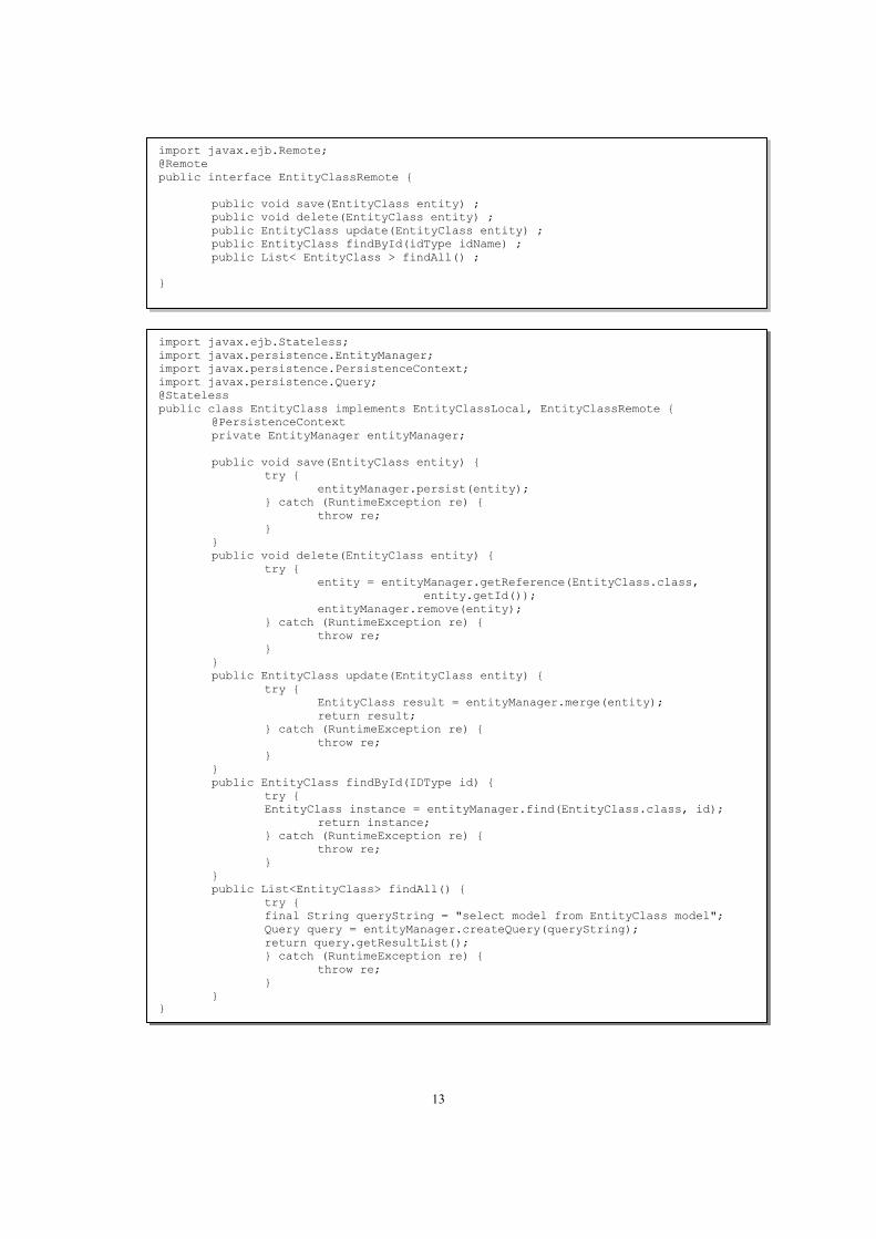
import javax.ejb.Remote;
@Remote
public interface EntityClassRemote {
public void save(EntityClass entity) ;
public void delete(EntityClass entity) ;
public EntityClass update(EntityClass entity) ;
public EntityClass findById(idType idName) ;
public List< EntityClass > findAll() ;
}
import javax.ejb.Stateless;
import javax.persistence.EntityManager;
import javax.persistence.PersistenceContext;
import javax.persistence.Query;
@Stateless
public class EntityClass implements EntityClassLocal, EntityClassRemote {
@PersistenceContext
private EntityManager entityManager;
public void save(EntityClass entity) {
try {
entityManager.persist(entity);
} catch (RuntimeException re) {
throw re;
}
}
public void delete(EntityClass entity) {
try {
entity = entityManager.getReference(EntityClass.class,
entity.getId());
entityManager.remove(entity);
} catch (RuntimeException re) {
throw re;
}
}
public EntityClass update(EntityClass entity) {
try {
EntityClass result = entityManager.merge(entity);
return result;
} catch (RuntimeException re) {
throw re;
}
}
public EntityClass findById(IDType id) {
try {
EntityClass instance = entityManager.find(EntityClass.class, id);
return instance;
} catch (RuntimeException re) {
throw re;
}
}
public List<EntityClass> findAll() {
try {
final String queryString = "select model from EntityClass model";
Query query = entityManager.createQuery(queryString);
return query.getResultList();
} catch (RuntimeException re) {
throw re;
}
}
}
13
7. CONCLUSION AND PERSPECTIVES
In this paper we have defined a method that performs firstly a M2M transformation to obtain a Java Model from TSD and DCD source models and then apply an EJB 3 profile to extend this target model with new features. Finally, we perform a M2T transformation that generates automatically a set of basic operations signatures from the generated structural model of the first transformation. The operations generated by our method suffice to cover all basic methods related to the system complex classes which change usually their states. Also, we generate the operations necessary to manage the life-cycle (CRUD) of data.
Our proposal improves also the quality and productivity of the design task related to the complex classes in the software development process by including the MDA concepts, meta-modeling and model transformation, to automate this software iteration and avoid design errors made by designers.
Model-driven software engineering is seen as a potential approach to improve software quality and reduce production, maintenance and evolution costs significantly. Our work falls into this category of research that aims to automate the passage between the software increments by proposing a set of model transformation and it opens also new perspectives to complete the automation of the entire software development process.
REFERENCES
[1] MDA GUIDE, Version 1.0.1 Object Management Group document number omg/2003-06-01 (http://www.omg.org/docs/omg/03-06-01.pdf)
[2] OMG :Object Management Group. www.omg.org http://www.omg.org/docs/omg/03-06-01.pdf
[3] Object Management Group, Inc. Unified Modeling Language (UML) 2.1.2 Infrastructure, November 2007. Final Adopted Specification.
[4] Object Management Group, Inc. Unified Modeling Language (UML) 2.1.2 Superstructure, November 2007. Final
Adopted Specification.
[5] Object Management Group, Inc. Meta Object Facility (MOF) 2.0 Core Specification, January
[6] J. Bézivin, Search of a basic principle for model driven engineering, UPGRADE European Journal for the
Informatics Professional V (2) (2004) 21–24.
[7] T. Mens, P. Van Gorp, A taxonomy of model transformation, Electronic Notes in Theoretical Computer Science 152 (2006) 125–142.
[8] A. Kleppe, J. Warmer, W. Bast, MDA Explained: The Model Driven Architecture™: Practice and Promise, Addison Wesley, 2003. p. 192.
[9] S.J. Mellor, K. Scott, A. Uhl, D. Weise, MDA Distilled: Principles of Model-Driven Architecture, A. Wesley, 2004. p. 176.
[10] P. Harmon, The OMG’s model driven architecture and BPM, Business Process Trends 2 (5) (2004).
[11] Object Management Group, Meta Object Facility (MOF) 2.0 Query/View/Transformation Specification, OMG
Adopted Specification ptc/05-11-01, 2005, p. 204.
[12] I. Kurtev, State of the art of QVT: a model transformation language standard, in: Applications of Graph Transformations with Industrial Relevance, Third International Symposium (AGTIVE), Kassel, Germany, 2007.
[13] Jean Bézivin , Erwan Breton , Grégoire Dupé , Patrick Valduriez ,-The ATL Transformation-based Model (2003) ,
Management Framework, Research Report, Atlas Group, INRIA and IRIN
[14] Freddy Allilaire , Jean Bézivin , Frédéric Jouault , Ivan Kurtev, ATL – Eclipse Support for Model Transformation
(2006) : Proc. of the Eclipse Technology eXchange Workshop (eTX) at ECOOP
[15] Ivan Kurtev , Atlas Group , Rule-based Modularization in Model Transformation Languages illustrated with ATL (2006) : 21st Annual ACM Symposium on Applied Computing (SAC2006)
[16] ATL - a model transformation technology, http://www.eclipse.org/atl/
[17] OMG, « Object Constraint Language (OCL) Specification, version 2.0 », 2006. http ://www.omg.org/spec/OCL/2.0/.
[18] Girault, C., Valk, R., 2003. Petri-Nets for Systems Engineering. Springer,Berlin.
[19] Uzam, M., Jones, A.H., 1998. Discrete event control system design using automation Petri nets and their ladder diagram implementation. International Journal of Advanced Manufacturing Systems 14 (10), 716–728.
[20] Lee, G., Zandong, H., Lee, J., 2004. Automatic generation of ladder diagram with control Petri Nets. Journal of Intelligent Manufacturing 15.
14
[21] Manoli Albert , Jordi Cabot , Cristina Gómez , Vicente Pelechano , Generating operation specifications from UML class diagrams: A model transformation approach, Data & Knowledge Engineering 70 (2011) 365–389
[22] Anis Charfi, Heiko Müller, Andreas Roth, Axel Spriestersbach, From UML Actions to Java, IDM 2009, Actes des 5emes journées sur l’Ingénierie Dirigée par les Modèles ,Nancy, 25-26 mars 2009
[23] OMG, Metamodel and UML Profile for Java and EJB Specification , February 2004, Version 1.0 formal/04-02-02
[24] EL BEGGAR Omar, BOUSETTA Brahim, GADI Taoufiq. Generating methods signatures from transition state
diagram : A model transformation approach. Information Science and Technology (CIST), 2012 IEEE Colloquium in Fez, 4-9. DOI: 10.1109/CIST.2012.6388054.
[25] BOUSETTA Brahim, EL BEGGAR Omar, GADI Taoufiq. Automating software development process: Analysis-PIMs to Design-PIM model transformation.
[26] EL BEGGAR Omar, BOUSETTA Brahim, GADI Taoufiq. Automatic code generation by model transformation
from sequence diagram of system’s internal behavior. International Journal of Computer and Information
Technology (IJCIT) December 2012 Volume 1, Issue: 2. p129-146.
[27] BOUSETTA Brahim, EL BEGGAR Omar, GADI Taoufiq. A methodology for CIM modelling and its
transformation to PIM. Journal of Information Engineering and Applications ISSN 2224-5782 (print) ISSN 2225-0506 (online) Vol 3, No. 2 p1-24, 2013
[28] Philip Langer, Konrad Wieland, Manuel Wimmer, and Jordi Cabot: " From UML Profiles to EMF Profiles and
Beyond " In Proceedings of the 49th Conference on Objects, Models, Components and Patterns (TOOLS'11), 2011.
LNCS 6705, Springer.
[29] OMG, Metamodel and UML Profile for Java and EJB Specification , February 2004, Version 1.0 formal/04-02-02
[30] EJB profile, Java Community Process under JSR-000026 (see http://jcp.org/jsr/detail/26.jsp).
[31] Linda DeMichiel (Sun Microsystems), Michael Keith (Oracle Corporation), JSR 220: Enterprise JavaBeansTM,Version 3.0, May 2, 2006
15