Embed Size (px)
Citation preview
Published: April 21, 2011
r 2011 American Chemical Society 6031 dx.doi.org/10.1021/la2004326 | Langmuir 2011, 27, 6031–6041
ARTICLE
pubs.acs.org/Langmuir
A Model of Electrowetting, Reversed Electrowetting, and ContactAngle SaturationDan Klarman and David Andelman*
Raymond & Beverly Sackler School of Physics and Astronomy, Tel-Aviv University, Ramat Aviv 69978, Tel Aviv, Israel
Michael Urbakh
Raymond & Beverly Sackler School of Chemistry, Tel-Aviv University, Ramat Aviv 69978, Tel Aviv, Israel
I. INTRODUCTION
The term electrowetting, in its broadest sense, refers to techniquesby which one can control the apparent wettability (characterized bythe contact angle) of liquids, by applying an external electricpotential.1�11 While it has numerous applications,12�20 electrowet-ting is known to be limited by the so-called contact angle saturation(CAS)5,7,21�27 as depicted in Figure 1. As the term indicates, anelectric potential can incur a change in the contact angle, but only to acertain extent. Further voltage increase has no additional effect on thecontact angle. This behavior is not accounted for by the standardmodel of electrowetting, and its origin still remains a point ofcontroversy.5�7,12,21�33
When a small drop of liquid is placed on top of a solid surface, itassumes the shape of a spherical cap.34 The contact angle θ0between the drop and the surface, given by the Young formula,34�36
cos θ0 ¼ γsa � γslγla
ð1Þdepends on the three interfacial tensions: solid/air γsa, solid/liquidγsl, and liquid/airγla, where the air phase can be replaced by anotherimmiscible fluid.7,17,19
The Young formula, eq 1, can be obtained by minimizing thecapillary free energy with a fixed volume constraint36
FcapðθÞ ¼ Asaγsa þ Aslγsl þ Alaγla � VΔP ð2Þ
where Aij are the interface areas between the i and j phases, i,j = a(air), l (liquid), and s (solid); the drop volume is V, and thepressure difference across the liquid/air interface is ΔP. Forpartial wetting, γsa < γslþ γla, the capillary free energy Fcap has aminimum at the Young angle, θ0 (Figure 2a).
The contact angle θ can be varied from its initial value θ0 byapplying an external voltage of several volts to several hundredsof volts across the liquid drop. A commonly used electrowettingsetup developed by Rinkel et al.1 and later perfected by Valletet al.5 is called electrowetting-on-dielectric (EWOD). Theapparatus, roughly sketched in Figure 3a, includes a flat electrodeas a substrate, which is coated with a thin dielectric layer (tensof nanometers to several micrometers thick), whose purpose isto prevent Faradic charge exchange (i.e., electrochemical re-actions) at the electrode. It is common that this dielectric layer isthen topped with an even thinner hydrophobic (i.e., Teflon)layer in order to control its surface tension. A drop of ionicsolution is placed atop the coated electrode, and a thin counter-electrode (usually a bare platinum fiber) is inserted into the dropfrom above. The drop is surrounded by air or by another
Received: February 1, 2011Revised: March 23, 2011
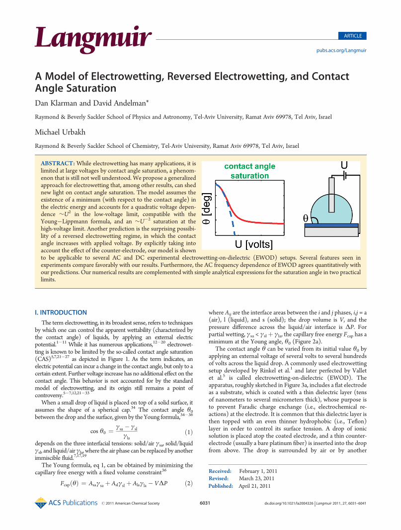
ABSTRACT:While electrowetting has many applications, it islimited at large voltages by contact angle saturation, a phenom-enon that is still not well understood. We propose a generalizedapproach for electrowetting that, among other results, can shednew light on contact angle saturation. The model assumes theexistence of a minimum (with respect to the contact angle) inthe electric energy and accounts for a quadratic voltage depen-dence ∼U2 in the low-voltage limit, compatible with theYoung�Lippmann formula, and an ∼U�2 saturation at thehigh-voltage limit. Another prediction is the surprising possibi-lity of a reversed electrowetting regime, in which the contactangle increases with applied voltage. By explicitly taking intoaccount the effect of the counter-electrode, our model is shownto be applicable to several AC and DC experimental electrowetting-on-dielectric (EWOD) setups. Several features seen inexperiments compare favorably with our results. Furthermore, the AC frequency dependence of EWOD agrees quantitatively withour predictions. Our numerical results are complemented with simple analytical expressions for the saturation angle in two practicallimits.

6032 dx.doi.org/10.1021/la2004326 |Langmuir 2011, 27, 6031–6041
Langmuir ARTICLE
immiscible dielectric liquid. Applying a voltage across the dropcan cause a large change, of several tens of degrees, in thecontact angle.
As reviewed in ref 12, a simple relation between the contactangle and the applied voltage can be derived. When an externalvoltage U is applied, an electric double layer is formed at theliquid/substrate interface. The total free energy Ftot has twocontributions: a capillary term Fcap defined37 in eq 2, and an
electric term Fel that depends on θ, U, and other systemparameters.
Ftotðθ,UÞ ¼ FcapðθÞ þ Felðθ,UÞ ð3ÞWithin the standard model of electrowetting (under externalvoltage control), the electric term is evaluated as
Fel ¼ � 12CldU
2 ð4Þ
where Cld is the capacitance of the liquid/substrate interface,which is modeled as a parallel-plate capacitor:
Cld = ε0Alddεd
þ λDεl
� ��1
=ε0εdd
Ald ð5Þ
whereAld is the substrate area that is covered by the liquid drop, dis the width of the dielectric layer, and εd and εl are the dielectricconstants of the dielectric coating and liquid drop, respectively.The Debye screening length, λD, is the width of the electricdouble layer. In most cases, d/εd . λD/εl, and the secondapproximation in eq 5 can be justified. The parallel-platecapacitor model has been shown10 to be valid as long as fringefields are negligible (d, Ald
1/2) and the drop of volume V is nottoo small for double layers to be created (λD,V1/3). An implicit
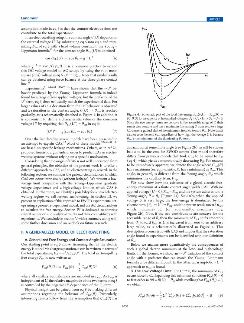
Figure 1. Schematic plot of electrowetting contact angle, θ(U). Forzero voltage, the contact angle is the same as the Young angle, θ0. At lowapplied voltages, U, the contact angle follows the Young�Lippmannformula, eq 6 (dashed line), cos θ(U) � cos θ0 = cos θYL(U) � cosθ0 ∼ U2, but for higher voltages the contact angle gradually deviatesfrom the Young�Lippmann behavior and saturates toward some finitevalue, θsat.
Figure 2. Schematic plots of (a) the capillary free energy Fcap for aspherical drop of fixed volume and (b) a hypothetical (negative) totalcapacitance, �Ctot, as function of contact angle θ in the electrowettingsetup. Theminimum of the capillary term Fcap occurs at the Young angleθ0, while the electric term Fel =�1/2CtotU
2 (or equivalently of�Ctot) isassumed to have a minimum at a finite saturation angle, θsat.
Figure 3. (a) Sketch of an EWOD setupwith AC voltageU of frequencyf and (b) its equivalent AC circuit. The two parallel-plate capacitors ofcapacitances C1 and C2 and areas A1 and A2 represent the substrate/liquid and the counter-electrode/liquid interfaces, respectively. The bulkliquid drop is represented by a resistor R1 through which the twocapacitors are charged and discharged. The charging time through theresistor is equal to the build-up time τb of the double layers at the twointerfaces. The discharge resistor R2 represents the Faradic chargetransfer processes that relax the electric double layer near the counter-electrode with relaxation time τr. Such a mechanism is prevented at thesubstrate electrode because of its dielectric coating.
6033 dx.doi.org/10.1021/la2004326 |Langmuir 2011, 27, 6031–6041
Langmuir ARTICLE
assumption made in eq 4 is that the counter-electrode does notcontribute to the total capacitance.
In an electrowetting setup, the contact angle θ(U) depends onthe external voltage U. By substituting eq 5 into eq 4 and mini-mizing Ftot of eq 3 with a fixed volume constraint, the Young�Lippmann formula12 for the contact angle θYL(U) is obtained
cos θYLðUÞ ¼ cos θ0 þ g�1U2 ð6Þwhere g�1 � ε0εd/(2γlad). It is a common practice to extendthis DC voltage model to AC setups by using the root meansquare (rms) voltage in eq 6,U2fUrms
2 . Note that similar resultscan be obtained using force balance at the three-phase contactline.38
Experiments5�7,12,21�24,29�31 have shown that the ∼U2 be-havior predicted by the Young�Lippmann formula is indeedfound for a range of low applied voltages, but the prefactor of theU2 term, eq 6, does not usually match the experimental data. Forlarger values of U, a deviation from the U2 behavior is observedand a saturation in the contact angle, θ(U) f θsat, is reachedgradually, as is schematically sketched in Figure 1. In addition, itis convenient to define a characteristic value of the crossovervoltage U* by requiring that θYL(U*) = θsat in eq 6:
ðU�Þ2 ¼ gðcos θsat � cos θ0Þ ð7ÞOver the last decades, several models have been presented in
an attempt to explain CAS.12 Most of these models7,22,26,31�33
are based on specific leakage mechanisms. Others, as in ref 24,proposed heuristic arguments in order to predict CAS in electro-wetting systems without relying on a specific mechanism.
Considering that the origin of CAS is not well understood fromgeneral principles, the objective of the present work is to offer adifferent approach to CAS, and to electrowetting in general. In thefollowing section, we consider the general circumstances in whichCAS can occur intrinsically (without leakage). We present a low-voltage limit compatible with the Young�Lippmann quadraticvoltage dependence and a high-voltage limit in which CAS isobtained. Furthermore, we identify a possibility for a novel electro-wetting regime we call reversed electrowetting. In section III, wepresent an application of this approach to EWODexperimental set-ups using a geometry-dependentmodel, and use AC circuit analysisto calculate the free energy. Section IV is dedicated to showingseveral numerical and analytical results and their compatibility withexperiments. We conclude in section V with a summary along withsome further discussion and an outlook on future research.
II. A GENERALIZED MODEL OF ELECTROWETTING
A. Generalized Free Energy and Contact Angle Saturation.Our starting point is eq 3 above. Assuming that all the electricenergy is stored via charge separation, it can be written in terms ofthe total capacitance, Fel = �1/2CtotU
2. The total electrocapillaryfree energy Ftot is now written as
Ftotðθ,UÞ ¼ FcapðθÞ � 12CtotðθÞU2 ð8Þ
where all capillary contributions are included in Fcap. As Fcap isindependent ofU, the relative magnitude of the two terms in eq 8is controlled by the negative U2 dependence of the Fel term.Physical insight can be gained from eq 8 by making different
assumptions regarding the behavior of Ctot(θ). Particularly,interesting results follow from the assumption that Ctot(θ) has
a maximum at some finite angle (see Figure 2b), as will be shownbelow to be the case for EWOD setups. Our model thereforediffers from previous models that took Ctot to be equal to Cld
(eq 4), which yields a monotonically decreasing Fel. For reasonsto be immediately apparent, we denote the angle where Ctot(θ)has amaximum (or, equivalently, Fel has aminimum) as θsat. Thisangle, in general, is different from the Young angle, θ0, whichminimizes the capillary term, Fcap.We now show how the existence of a global electric free-
energy minimum at a finite contact angle yields CAS. With noapplied voltage (U = 0), Ftot = Fcap and the system adheres to theYoung angle, θ = θ0 (Figure 2a). Similarly, when the appliedvoltage U is very large, the free energy is dominated by theelectric term, |Fel|�U2. Fcap, and the system tends toward θsat,which minimizes Fel (or, equivalently, maximizes Ctot;Figure 2b). Now, if the two contributions are concave for theaccessible range of θ, then the minimum of Ftot shifts smoothlyfrom θ0 toward θsat as U is increased from zero to an arbitrarylarge value, as is schematically illustrated in Figure 4. Thisdescription is consistent with CAS and implies that the saturationangle found in experiments can be identified with our definitionof θsat.Below we analyze more quantitatively the consequences of
such a global electric minimum at the low- and high-voltagelimits. In the former, we show an ∼U2 variation of the contactangle with a prefactor that can match the Young�Lippmannformula or be different from it. In the latter, an asymptotic∼U�2
approach to θsat is found.B. The Low Voltage Limit. For U f 0, the minimum of Ftot
occurs close to θ0. Expanding this minimum condition F 0tot(θ) = 0
to first order in δθ = θ(U)� θ0, while recalling that Fcap0 (θ0) = 0,we obtain
F00capðθ0Þδθ� 12U2 C0
totðθ0Þ þ C00totðθ0Þδθ
� �= 0 ð9Þ
Figure 4. Schematic plot of the total free energy Ftot(θ,U) = Fcap(θ) þFel(θ,U) for a sequence of five applied voltages:U4 >U3 >U2 >U1 >U= 0.Since the two energy terms are concave in the accessible range of θ, theirsum is also concave and has a minimum. IncreasingU from zero to a largeU4 causes a gradual shift of the minimum from θ0 toward θsat. Note that itcannot cross beyond θsat regardless of how high the voltage U is becauseθsat is the minimum of the dominating Fel term.

6034 dx.doi.org/10.1021/la2004326 |Langmuir 2011, 27, 6031–6041
Langmuir ARTICLE
yielding
δθ =12
C0totðθ0Þ
F00capðθ0Þ � 12U2C00
totðθ0ÞU2 ð10Þ
and to leading order in U2 one has
θðUÞ = θ0 þ 12C0totðθ0Þ
F00capðθ0ÞU2 ð11Þ
and equivalently
cos θðUÞ = cos θ0 � 12C0totðθ0Þsin θ0F00capðθ0Þ U2 ð12Þ
We see that, at low voltages, the deviation from the Youngangle is proportional to U2, just as in the Young�Lippmannformula. However, the prefactor is a function of θ0 and can takedifferent values than in eq 6, and even change its sign (see sectionII.D). It is shown in section IV.D under which conditions theprefactor converges to that of the Young�Lippmann formula forlow voltages in typical EWOD experimental setups.C. The High Voltage Limit. For U f ¥, the electric energy
becomes large relative to the capillary energy and so the mini-mum of Ftot occurs at θ(U) = θsatþ δθ. Expanding the conditionFtot0 (θ) = 0 around θsat, one has
F0capðθsatÞ þ F00capðθsatÞ δθ� 12C00
totðθsatÞU2 δθ = 0 ð13Þ
or
θðUÞ = θsat þ F0capðθsatÞ12U2C00
totðθsatÞ � F00capðθsatÞ= θsat þ 2
F0capðθsatÞC00
totðθsatÞU�2
ð14ÞHence, saturation in θ is approached asymptotically, as U�2, inqualitative agreement with experiments.12,14
D. Reversed Electrowetting. An interesting conclusion canbe drawn from the discussion in section II.A. Recalling that in ourmodel electrowetting results from an interplay between capillaryand electric energies (each with its own minimum at θ0 and θsat,respectively); as voltage is increased, the electric energy graduallybecomes dominant and the contact angle is driven away from θ0toward θsat (Figure 4). Since θ0 is determined only by thecapillary parameters (as in the Young formula, eq 1) and θsat isdetermined solely by the electric parameters, it is possible toenvisage a system in which the saturation angle θsat is actuallylarger than the Young angle, θsat > θ0 rather than θsat < θ0 as inthe usual case. In such a setup, applying a voltage will cause anincrease of the contact angle, in total contradiction with theYoung�Lippmann formula, eq 6. Hence, the model proposedhere allows for the possible existence of a new regime ofelectrowetting, which we refer to as reversed electrowetting.By examining the slopes of each energy term near the
minimum of the other (see Figure 2), it is possible to show that,in the low- and high-voltage limits, eqs 11 and 14, the prefactorsof both U2 and U�2 terms can take either positive or negativevalues depending on whether θ0 > θsat or θ0 < θsat; for the low-voltage limit, Fcap00 (θ0) is positive by definition, but Ctot
0 (θ0) ispositive only if θ0 > θsat and negative for θ0 < θsat. Likewise, forthe high-voltage limit, Ctot
00 (θsat) is negative by definition, butFcap0 (θsat) is negative only if θ0 > θsat and positive for θ0 < θsat.
Thus, we have shown how reversed electrowetting manifestsitself in those limits.
III. A TWO ELECTRODE MODEL OF EWOD
Our goal in the remainder of this work is to elaborate on thephysical conditions that are involved in determining a finite θsatangle in specific EWOD experimental setups. However, we wouldlike to stress that the proposed mechanism is general and may beapplied to other realizations and experimental setups manifes-ting CAS.A. SystemSetup andGeometry.A setup of an EWOD is pre-
sented in Figure 5. The drop (dielectric constant εl) is assumedto retain its spherical-cap shape, with height h from the surface,total volume V, and contact angle θ. The metal electrode iscoated with a dielectric layer of thickness d and dielectric con-stant εd. The top counter-electrode is modeled as a thin cylinderof radius b and the gap between the two electrodes is hg. The twoelectrode areas covered by the liquid are A1 and A2, respectively.For spherical-cap shaped drops, A1 and A2 are related to thecontact angle θ through the fixed volume constraint:
A1¼ πa2
A2¼ 2πbðh� hgÞtan
θ
2¼ h
a
V¼ πh6ð3a2 þ h2Þ ð15Þ
where a is the radius of the covered portion of the substrateelectrode.
Figure 5. Schematic EWOD setup as used in our analysis. A liquid dropshaped as a spherical cap of volume V, height h, and dielectric constant εlis placed atop a flat metal electrode. The metal electrode is covered witha dielectric coating of thickness d and dielectric constant εd. A metal wire(used as a counter-electrode), modeled as a thin cylinder of radius b, isinserted into the drop from above. The gap between the two electrodes ishg. The area of the substrate electrode covered by the drop is A1 and thatof the counter-electrode is A2. The applied voltage is U and the contactangle with the substrate is θ.
6035 dx.doi.org/10.1021/la2004326 |Langmuir 2011, 27, 6031–6041
Langmuir ARTICLE
It should be noted that θ can only take values in the rangeθmin < θ < π. The lower limit, θmin, occurs when the drop heightmatches the gap between the lower tip of the counter-electrodeand the substrate, h = hg (see Figure 5), resulting in
cotθmin2
¼ffiffiffiffiffiffiffiffiffiffiffiffiffiffiffiffiffi2V
πhg3 �
13
sð16Þ
We will show that θsat > θmin and hence θmin is an inaccessiblelower bound of the contact angle. The upper limit θ = π is thedewetting limit.B. The AC Free-Energy.The free energy, eq 8, depends on the
total capacitance Ctot, which includes all relevant contributions.Unlike the traditional Young�Lippmann treatment in whichonly the capacitance of the liquid/substrate interface is taken intoaccount, we consider explicitly the existence of an additionaldouble-layer, residing at the interface between the liquid dropand the counter-electrode.Experimental setups and applications usually employ AC
circuits to produce an electrowetting effect. Under those circum-stances, double layers are transient: with each AC half-cycle, adouble layer of opposite polarity is formed at each electrode/liquid interface and subsequently dissolved away. In addition torelaxation by reversal of polarity, other mechanisms of relaxationcan act at the counter-electrode/liquid interface such as electro-chemical Faradic processes. The dynamical processes are, there-fore, governed by two intrinsic time scales (beside the ACfrequency):1. The double-layer build-up time, τb, which can be estimated
to be
τb =λDLD
ð17Þ
where λD = [(ε0εlkBT)/(2e2csalt)]
1/2 is the Debye length,kBT is the thermal energy, csalt is the salt concentration,D isthe diffusion constant, and L is a typical system size.39
2. The double-layer relaxation time, τr, which can similarly beexpressed in terms of system parameters through the RCcircuit relaxation formula
τr ¼ R2C2 ¼ τC2
A2ð18Þ
where F = R2A2 is defined as the zero-current (Faradic)resistivity to charge transfer by electrochemical processesand A is the contact area.
In order to discuss the period-averaged properties of the system,we employ a standard AC circuit analysis. As shown in Figure 3b,we model the two liquid/electrode interfaces as two capacitorswith capacitances C1,C2, defined in a similar fashion as in eq 5:
C1 ¼ Cld =ε0εdA1
d
C2 =ε0εlA2
λD
ð19Þ
Note that the main contribution to C1 comes from the coateddielectric layer of thickness d (d/εl. λD/εl), while forC2 the onlycontribution comes from the double layer of thicknessλD (becausethe counter-electrode is not coated). The cylindrical geometry ofthe counter-electrode is not considered because b . λD.The two capacitors are charged and discharged through a
resistor R1 that represents the bulk of the liquid drop. The
relaxation of the double layer at the counter-electrode is modeledby an extra discharge circuit with a resistor R2, while the capacitorC1 does not have a discharge circuit since charge transfer at thesubstrate electrode is prevented by its dielectric coating. Theappropriate resistance values can be inferred from the build-up(τb) and relaxation (τr) times, eqs 17 and 18, again through theRC circuit relaxation formula:
R1 ¼ τb C1�1 þ C2
�1� �
R2 ¼ τrC2
ð20Þ
Drawing on the AC circuit analogy, the period-averaged freeenergy is:
Ftotðθ,U ,ωÞ ¼ Fcap þ Fel
¼ FcapðθÞ � 12
1ωjZtotðθ,ωÞjU
2 ð21Þ
where U is understood to be the rms value and Ztot is the totalimpedance of the circuit (Figure 3b), which can be representedschematically as
Ztot ¼ ZC1 x ZR1 x ZC2 jjZR2
� � ð22ÞIt is straightforward to show that the squared magnitude of thetotal impedance is
jZtotj2 ¼ 1C1
2 τb2 þω�2
� �þ 2C1C2
τb2 þ τrðτr þ τbÞ
1þω2τr2
� �
þ 1C2
2 τb2 þ τrðτr þ 2τbÞ
1þω2τr2
� �ð23Þ
SinceC1 is proportional toA1, which vanishes at θfπ, andC2
is proportional to A2, which vanishes at θf θmin, |Ztot|2 diverges
at both θf θmin and θf π. Therefore, it must have a minimumat some intermediate value: θmin < θsat < π. Hence, our model of
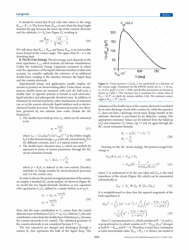
Figure 6. Total reactance 1/(ωZtot) (in nanoFarad) as a function ofthe contact angle. Parameters for the EWOD system are τb = 1.34 ms,τr = 0.53 s, and f =ω/2π = 1 kHz, and all other parameters are chosen asshown in Table 1. The reactance has a maximum for a finite value ofθsat = 53.3�, at which the system exhibits CAS. The minimal contactangle is θmin = 37�, eq 16.

6036 dx.doi.org/10.1021/la2004326 |Langmuir 2011, 27, 6031–6041
Langmuir ARTICLE
electrowetting presented in section II.A is indeed applicable totypical EWOD setups.Substituting eqs 15 and 19 into eqs 21 and 23 yields an
expression for C1(θ) and C2(θ) and, consequently, for Fel as afunction of θ. Its minimization can be done numerically (sectionIV.A) and yields the equilibrium contact angle (for given appliedvoltage and frequency). In some limits (sections IV.C and IV.E),analytical approximations can be derived as well.
IV. RESULTS AND DISCUSSION
A. The Electrowetting Curve, θ(U). In order to demonstratequantitatively the model validity, we performed numerical calcu-lations for parameter values that are in accord with some typical
experimental setups. In Figure 6, we present the reactance1/ωZ (appearing in eq 21) computed for parameter values asin Table 1 and with an AC frequency f = ω/2π = 1 kHz. Thebuild-up time was calculated using eq 17 to be τb = 1.34 ms, whilethe relaxation time was calculated using eq 18 with40 F = 1Ω 3m
2,yielding44 τr = 0.53 s. For the chosen values of parameters, theratio of capacitances for zero voltages (θ(U = 0) = θ0) is aboutC2/C1= 25. In the figure, a maximum at a finite angle θsat = 53.3�is clearly seen. Notably, this saturation angle is much larger thanthe minimal possible angle in this setup, θmin = 37� (see eq 16).As a consequence, CAS is obtained for finite values of A2, muchbefore the limit A2 f 0 characteristic to θmin.Figure 7 presents the calculated electrowetting curve θ(U) for
the same system,whereθ(U) is calculated byminimizing Ftot fromeq 21, together with a plot of the Young�Lippmann formulawhere an effective geff prefactor is used to fit the full calculation.This is similar to what is done in many experimental works where
Table 1. Parameter Values of a Typical Electrowetting Setupa
parameter symbol value
dielectric constant of liquid εl 80
Debye length in liquid λD 1.34 nm
volume V 5 μL
width of dielectric layer d 0.1 μm
dielectric constant of dielectric layer εd 2.67
liquid/air surface tension γla 72.8 mN/m
dielectric/air surface tension γsa 12.7 mN/m
liquid/dielectric interfacial tension γsl 47 mN/m
gap between counter-electrode and substrate hg 0.7 mm
radius of counter-electrode b 12.5 μmaThe liquid drop contains an aqueous ionic solution and is placed on topof a Miyaline-C/Teflon substrate.
Figure 7. Calculated contact angle as a function of applied voltage, U(full line), as well as a plot of the Young�Lippmann formula (dash-dotted) using geff (dashed line, see text). Parameter values of theEWOD system are taken from Table 1 and τb = 1.34 ms, τr = 0.53 s,and f =ω/2π = 1 kHz.Many of the features of CAS, shown schematicallyin Figure 1, are reproduced. AtU = 0, the contact angle is θ0 = 118�. Forsmall U, there is an initial compliance with the rescaled Young�Lippmann formula, eq 6, θ(U) ≈ θYL(U), followed by a crossoveroccurring at U* = 76.9 V, calculated from eq 7. At larger U, the contactangle tends asymptotically to a saturation angle θsat = 53.3�. Theasymptotic θ(U) � θsat ∼ U�2 is plotted (dotted line) followingeq 14 and approximates rather well θ(U) for voltages larger than120 V. An operational definition of the saturation voltage Usat (see text)yields Usat = 252.1 V. Note that θsat is conceivably larger than theminimal possible angle θmin = 37�, eq 16.
Table 2. Parameter Values of a Hypothetical Reversed Elec-trowetting Setup
parameter value
εl 2
λD 1.34 nm
V 5 μL
d 0.1 μm
εd 2.67
γla 20 mN/m
γsa 15 mN/m
γsl 5 mN/m
hg 0.7 mm
b 12.5 μm
Figure 8. Calculated contact angle as a function of applied voltage, U(solid line), for reversed electrowetting together with a manually scaled(geff < 0) Young�Lippmann formula (dashed line). Parameter values ofan EWOD system are taken fromTable 2, and τb = 1.34ms, τr = 13.2 ms,and f = ω/2π = 1 kHz. At U = 0, the contact angle is θ0 = 60�. Even forsmall U, there is a deviation from the naive Young�Lippmann formula,eq 6, because θ(U) � θ0 ∼ U2, with a positive prefactor. The U2 rise isfollowed by a crossover occurring atU* = 65.5 V. At largerU, the contactangle tends asymptotically to a saturation angle θsat = 101.9�. Usingthe same definition of the saturation voltage Usat as in Figure 7 yieldsUsat = 208.5 V.
6037 dx.doi.org/10.1021/la2004326 |Langmuir 2011, 27, 6031–6041
Langmuir ARTICLE
the g value is fitted from the low U dependence, and not by usingexplicitly eq 6. We use a specific geff = (1þ ω2τb
2)�1/2 as derivedin section IV.D. The figure shows that several common experi-mental features are reproduced (as compared with the schematicin Figure 1); an initial compliance with the scaled Young�Lippmann formula at low voltages is followed by a crossover atintermediate voltages to a different regime. Using eq 7 (with geff),the crossover voltage is evaluated to beU*= 76.9 V. AtU >U* anasymptotic convergence of the contact angle toward a saturationvalue is seen, θ(U)f θsat = 53.3�. This is further demonstrated inFigure 7, where the asymptotic θ(U) � θsat ∼ U�2 is plotted(dotted line) following eq 14. The asymptotic behavior approx-imates rather well θ(U) for voltages larger than 120 V.It is appropriate to define another voltage, Usat, characterizing
the saturation range of the potential. An operational definitionthat we employ is that at Usat, the calculated θ(Usat) deviatesfrom θsat by 2%. With this definition, we obtain Usat = 252.1 V.The electrowetting curve presented in Figure 7 agrees qualita-tively with experimental observations,8,12,28 which show theeffect of contact angle saturation. Unfortunately, because theparameter values needed for quantitative comparison withexperiments are lacking at present, we used instead reasonableestimations.B. The Reversed Electrowetting Curve, θ(U). We now
illustrate how reversed electrowetting θsat < θ0, which is a naturaloutcome of our model, can be seen in the laboratory. Let usconsider a system similar to the one presented in the previoussection with the two following changes (see Table 2): theinterfacial tensions are chosen such that θ0 = 60�, and we nowmodel a nonpolar liquid with a dielectric constant εl = 2, whichyields a build-up time of τb = 1.34 ms and a relaxation time ofτr = 13.2 ms. The AC frequency is f = ω/2π = 1 kHz as before.Figure 8 presents the calculated electrowetting curve θ(U).
The plot features an initial compliance with the negativelyrescaled Young�Lippmann formula (at low voltages such thatthe contact angle increases with the applied voltage). This isfollowed by a crossover at intermediate voltages toward satura-tion. Using eq 7 (with geff), the crossover voltage is evaluated to
be U* = 65.5 V. For U > U*, an asymptotic convergence of thecontact angle toward a saturation value is seen, θ(U) f θsat =101.9�. Using the same definition as in section IV.A, thesaturation voltage is found to be Usat = 208.5 V.Since our reversed electrowetting predictions (Figure 7) are
rather for specific parameter values, it will be of benefit to checktheir validity with experiments conducted on similar electrowet-ting setups.C. The Frequency Dependence of Electrowetting. In order
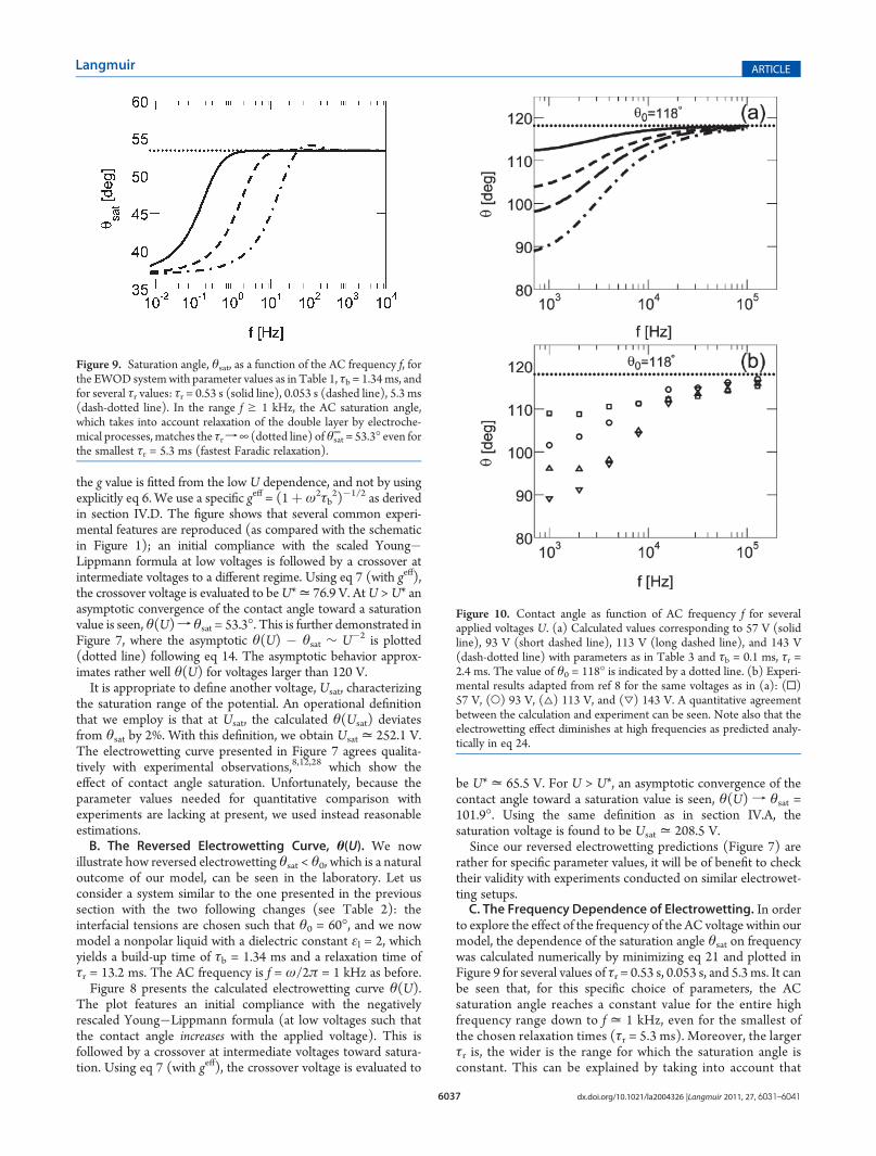
to explore the effect of the frequency of the AC voltage within ourmodel, the dependence of the saturation angle θsat on frequencywas calculated numerically by minimizing eq 21 and plotted inFigure 9 for several values of τr = 0.53 s, 0.053 s, and 5.3 ms. It canbe seen that, for this specific choice of parameters, the ACsaturation angle reaches a constant value for the entire highfrequency range down to f = 1 kHz, even for the smallest ofthe chosen relaxation times (τr = 5.3 ms). Moreover, the largerτr is, the wider is the range for which the saturation angle isconstant. This can be explained by taking into account that
Figure 9. Saturation angle, θsat, as a function of the AC frequency f, forthe EWOD systemwith parameter values as in Table 1, τb = 1.34ms, andfor several τr values: τr = 0.53 s (solid line), 0.053 s (dashed line), 5.3 ms(dash-dotted line). In the range f g 1 kHz, the AC saturation angle,which takes into account relaxation of the double layer by electroche-mical processes, matches the τrf¥ (dotted line) ofθsat
¥ = 53.3� even forthe smallest τr = 5.3 ms (fastest Faradic relaxation).
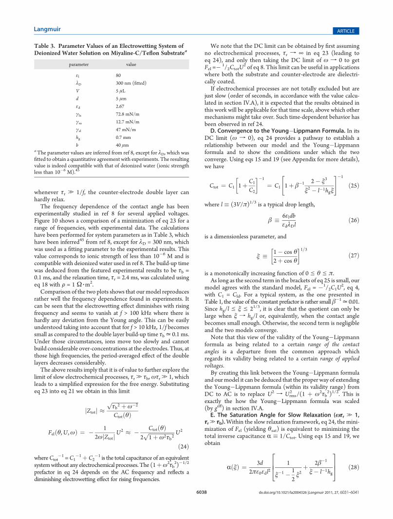
Figure 10. Contact angle as function of AC frequency f for severalapplied voltages U. (a) Calculated values corresponding to 57 V (solidline), 93 V (short dashed line), 113 V (long dashed line), and 143 V(dash-dotted line) with parameters as in Table 3 and τb = 0.1 ms, τr =2.4 ms. The value of θ0 = 118� is indicated by a dotted line. (b) Experi-mental results adapted from ref 8 for the same voltages as in (a): (0)57 V, (O) 93 V, (4) 113 V, and (3) 143 V. A quantitative agreementbetween the calculation and experiment can be seen. Note also that theelectrowetting effect diminishes at high frequencies as predicted analy-tically in eq 24.
6038 dx.doi.org/10.1021/la2004326 |Langmuir 2011, 27, 6031–6041
Langmuir ARTICLE
whenever τr . 1/f, the counter-electrode double layer canhardly relax.The frequency dependence of the contact angle has been
experimentally studied in ref 8 for several applied voltages.Figure 10 shows a comparison of a minimization of eq 23 for arange of frequencies, with experimental data. The calculationshave been performed for system parameters as in Table 3, whichhave been inferred45 from ref 8, except for λD = 300 nm, whichwas used as a fitting parameter to the experimental results. Thisvalue corresponds to ionic strength of less than 10�6 M and iscompatible with deionized water used in ref 8. The build-up timewas deduced from the featured experimental results to be τb =0.1 ms, and the relaxation time, τr = 2.4 ms, was calculated usingeq 18 with F = 1 Ω 3m
2.Comparison of the two plots shows that our model reproduces
rather well the frequency dependence found in experiments. Itcan be seen that the electrowetting effect diminishes with risingfrequency and seems to vanish at f > 100 kHz where there ishardly any deviation from the Young angle. This can be easilyunderstood taking into account that for f > 10 kHz, 1/f becomessmall as compared to the double layer build-up time τb= 0.1 ms.Under those circumstances, ions move too slowly and cannotbuild considerable over-concentrations at the electrodes. Thus, atthose high frequencies, the period-averaged effect of the doublelayers decreases considerably.The above results imply that it is of value to further explore the
limit of slow electrochemical processes, τr . τb, ωτr . 1, whichleads to a simplified expression for the free energy. Substitutingeq 23 into eq 21 we obtain in this limit
jZtotj �ffiffiffiffiffiffiffiffiffiffiffiffiffiffiffiffiffiffiffiffiτb2 þω�2
pCtotðθÞ
Felðθ,U ,ωÞ ¼ � 12ωjZtotjU
2 � � CtotðθÞ2ffiffiffiffiffiffiffiffiffiffiffiffiffiffiffiffiffiffiffi1þω2τb2
p U2
ð24ÞwhereCtot
�1 =C1�1þ C2
�1 is the total capacitance of an equivalentsystemwithout any electrochemical processes. The (1þω2τb
2)�1/2
prefactor in eq 24 depends on the AC frequency and reflects adiminishing electrowetting effect for rising frequencies.
We note that the DC limit can be obtained by first assumingno electrochemical processes, τr f ¥ in eq 23 (leading toeq 24), and only then taking the DC limit of ω f 0 to getFel =� 1/2CtotU
2 of eq 8. This limit can be useful in applicationswhere both the substrate and counter-electrode are dielectri-cally coated.If electrochemical processes are not totally excluded but are
just slow (order of seconds, in accordance with the value calcu-lated in section IV.A), it is expected that the results obtained inthis work will be applicable for that time scale, above which othermechanisms might take over. Such time-dependent behavior hasbeen observed in ref 24.D. Convergence to the Young�Lippmann Formula. In its
DC limit (ω f 0), eq 24 provides a pathway to establish arelationship between our model and the Young�Lippmannformula and to show the conditions under which the twoconverge. Using eqs 15 and 19 (see Appendix for more details),we have
Ctot ¼ C1 1þ C1
C2
�1
¼ C1 1þ β�1 2� ξ3
ξ2 � l�1hgξ
" #�1
ð25Þ
where l � (3V/π)1/3 is a typical drop length,
β � 6εldbεdλDl
ð26Þ
is a dimensionless parameter, and
ξ � 1� cos θ2þ cos θ
1=3ð27Þ
is a monotonically increasing function of 0 e θ e π.As long as the second term in the brackets of eq 25 is small, our
model agrees with the standard model, Fel = �1/2C1U2, eq 4,
with C1 = Cld. For a typical system, as the one presented inTable 1, the value of the constant prefactor is rather small β�1= 0.01.Since hg/l e ξ e 21/3, it is clear that the quotient can only belarge when ξ f hg/l or, equivalently, when the contact anglebecomes small enough. Otherwise, the second term is negligibleand the two models converge.Note that this view of the validity of the Young�Lippmann
formula as being related to a certain range of the contactangles is a departure from the common approach whichregards its validity being related to a certain range of appliedvoltages.By creating this link between the Young�Lippmann formula
and ourmodel it can be deduced that the proper way of extendingthe Young�Lippmann formula (within its validity range) fromDC to AC is to replace U2 f Urms
2 /(1 þ ω2τb2)1/2. This is
exactly the how the Young�Lippmann formula was scaled(by geff) in section IV.A.E. The Saturation Angle for Slow Relaxation (ωτr . 1,
τr. τb).Within the slow relaxation framework, eq 24, the mini-mization of Fel (yielding θsat) is equivalent to minimizing thetotal inverse capacitance R � 1/Ctot. Using eqs 15 and 19, weobtain
RðξÞ ¼ 3d2πε0εdl2
1
ξ�1 � 12ξ2
þ 2β�1
ξ� l�1hg
2664
3775 ð28Þ
Table 3. Parameter Values of an Electrowetting System ofDeionized Water Solution on Miyaline-C/Teflon Substratea
parameter value
εl 80
λD 300 nm (fitted)
V 5 μL
d 5 μm
εd 2.67
γla 72.8 mN/m
γsa 12.7 mN/m
γsl 47 mN/m
hg 0.7 mm
b 40 μmaThe parameter values are inferred from ref 8, except for λD, which wasfitted to obtain a quantitative agreement with experiments. The resultingvalue is indeed compatible with that of deionized water (ionic strengthless than 10�6 M).45
6039 dx.doi.org/10.1021/la2004326 |Langmuir 2011, 27, 6031–6041
Langmuir ARTICLE
Minimizing R(ξ) yields a sixth-order polynomial in ξ:
ξ6 � 2βξ5 þ 4βl�1hgξ4 � 2 2þ βl�2hg
2� �
ξ3 � 2βξ2
þ 4βl�1hgξþ 2 2� βl�2hg2
� � ¼ 0 ð29ÞIt is possible to examine two separate limits for minimizingR(ξ), leading to two simple analytical expressions for θsat.1. Acute Saturation Angles (Large β). If ξ3(θsat) , 2, then,
near its minimum, eq 28 reduces to
R�����ξ = ξsat
=3d
2πε0εdl2ξþ 2β�1
ξ� l�1hg
" #ð30Þ
with a minimum at ξ = ξsat that satisfies
1� 2β�1 ξsat �hgl
� ��2
¼ 0 ð31Þ
The solution yields
ξsat ¼ffiffiffi2β
rþ hg
lð32Þ
and θsat can now be obtained
cos θsat ¼ 1� 2ξsat3
1þ ξsat3 ð33Þ
Inserting typical values from Table 1 to check for self-consis-tency, we get ξsat
3 ≈ 0.173 , 2 as required. Using eq 33, thesaturation angle in this case is calculated to be θsat= 56.1�, whichis not far from the value obtained by a full numerical calculation,53.3�. As a rule of thumb, we remark that the above condition,ξsat3 , 2 holds for θsat smaller than π/2, for which ξ3(π/2) =0.5 , 2.2. Large Saturation Angles (Small β and hg/l). For systems
with small β, the above approximation should fail, as is apparentfrom eq 32. For such cases, we can use a different approximationassuming that the gap hg is small enough, such that
ξsat .hgl
ð34ÞThe saturation angle can then be found from a different
approximated form of R(ξ) (eq 28), near its minimum:
R�����ξ = ξsat
=3d
2πε0εdl21
ξ�1 � 12ξ2
þ 2β�1
ξ
2664
3775
¼ 3dπε0εdl2
1
2� ξ3þ β�1
ξ�1 ð35Þ
Minimizing R(ξ), we get a quadratic equation in the variable ξ3:
ξ6 � 4ðβþ 1Þξ3 þ 2ðβþ 2Þ ¼ 0 ð36Þwhose solution is
ξsat3 ¼ 2ðβþ 1Þ (
ffiffiffiffiffiffiffiffiffiffiffiffiffiffiffiffiffiffiffiffiffiffiffiffiffiffiffiffiffiffiffiffiffiffiffiffiffiffiffiffiffi4ðβþ 1Þ2 � 2ðβþ 2Þ
qð37Þ
For small β, it is possible to further simplify the expression for ξsatto obtain
ξsat3 = 2 1�
ffiffiffiffiffi3β2
r !ð38Þ
Checking for self-consistency, the condition holds for smallenough gaps.
V. SUMMARY AND OUTLOOK
In this work, we propose a novel approach toward electro-wetting that, among other results, can account for contact anglesaturation (CAS) applicable to some electrowetting setups. Themodel is based on a generalized version of the free energyaccounting for various electric contributions. The interplay betweenthe capillary (Fcap) and electric (Fel) terms depends on the appliedvoltage U, because Fel ∼ �U2. Therefore, when an externalvoltage is applied, it will drive the system away from its capillaryfree energy minimum and toward its electric free energy minimum.
Our approach is distinctly different from other views ofelectrowetting that make use of the Young�Lippmann formula.In our model, the electric term can exhibit a variety of depen-dencies on the contact angle as determined by the exact systemgeometry. Particularly, if the electric term Fel has a globalminimum at a certain contact angle θsat, then for high enoughvoltages this angle also minimizes (asymptotically) the total freeenergy Ftot. Additional increase of the applied voltage does notchange the location of the global minimum, and the contact anglesaturates at θsat. We identify exactly this angle with the saturationangle found in experiments. This very general assumption (Felwith a minimum) is all that is needed to show that in the low-voltage limit a Young�Lippmann compatible ∼U2 behavior isexpected, while in the high-voltage limit an∼U�2 saturation shouldbe present. Numerical calculations suggest that combination ofthese two limiting behaviors approximates rather well the fullexpression for θ(U) in the whole voltage range.
When applying our approach to EWOD setups, we take twocontributions to Fel into account: (i) the double layer at thedrop/substrate interface and (ii) another double layer at thedrop/counter-electrode interface. The latter was previouslyunaccounted for because it was considered to be negligible dueto geometry, or that its relaxation time was considered to be veryfast. However, we estimate the relaxation time to be long (on theorder of seconds) and, therefore, the effect of the counter-electrode double-layer cannot be neglected for AC systems.Similarly, it cannot be neglected for low voltages (which willexclude electrochemical processes from taking place at all)27 or inDC applications that include a dielectrically coated counter-electrode. Using AC circuit analysis, we show that Fel indeed has aglobal minimum that produces the CAS effect.
The value of the saturation angle as well as the entireelectrowetting curve θ(U) can be found numerically for anychoice of system parameters, and our specific choice is inspiredby the experiments reviewed in ref 12. There is a qualitativeagreement with experimental results, which includes an initialcompliance with the Young�Lippmann formula (scaledcorrectly), followed by a crossover to CAS. The values obtainedfor the saturation angle, crossover voltage, and saturation voltageare also compatible with experimental values.
In addition, we investigated the frequency dependence ofelectrowetting. It is shown that the value of the saturation angle isindependent of the AC frequency for a large range of frequencies(1�100 kHz) for a specific choice of parameters. A numericalanalysis of the frequency dependence of electrowetting wasconducted for a set of system parameters inferred from ref 8and shows semiquantitative agreement with the experiment.These results show that an approximation of the free energy
6040 dx.doi.org/10.1021/la2004326 |Langmuir 2011, 27, 6031–6041
Langmuir ARTICLE
can be justified, such that the entire frequency dependence iscaptured in a scaling factor of the applied voltage. It predicts thatthe electrowetting effect should diminish with rising frequency,as indeed found in experiments.8
In its DC limit, our model can converge to the Young�Lippmann formula, depending on the values of the Young andsaturation angles. We use this result to show a novel way toextend the Young�Lippmann formula from DC to AC systems.We conclude that the validity of the Young�Lippmann formulais related not to the range of applied voltages, as it is commonlyviewed, but rather to the accessed range of contact angles. Incommonly used EWOD setups, which are intentionally devisedto have as high a Young angle and as low a saturation angle aspossible (so the effect can bemore easily measured), ourmodel iscompatible with a compliance to the Young�Lippmann formulaat low voltages (and hence high contact angles).We note that theDC limit of our model can bemost useful in DC applications thatemploy low voltages and/or include a dielectrically coatedcounter-electrode.
Our model does not rely on any leakage mechanisms topredict CAS. Nevertheless, we would like to stress that leakagemechanisms treated in previous works7,22,26,31�33 can be added.Interestingly, it is conceivable that a crossover between inherentCAS (as in the present model) and CAS originating from leakagemechanisms is responsible for the time-dependent saturationangle reported in ref 24.
The fact that the saturation angle depends on electric parameterswhereas the Young angle depends on the capillary parameters leadsto the surprising possibility of reversed electrowetting. Therefore, itmay be possible to construct a system in which the Young angleis lower than the saturation angle. In such a system, the effectof applying an external voltage would be an increase in thecontact angle, in total contradiction with the Young�Lippmannformula that allows only a decrease in the contact angle. We give anexample of a choice of parameters that should yield reversedelectrowetting.
Recently, the separate control of the Young and saturationangles was demonstrated in experiments.46 This ability wasutilized to construct a set of dye cells47 that are “complementary”in their opposite response to applied voltage (black-to-white orvice versa). We believe that further research in this direction willprovide ample opportunity to test for the existence of reversedelectrowetting. Finding such evidence would have a potentialimpact that can go much beyond our specific model.
We hope that some of the predictions presented in this paperwill be tested in future experiments in a quantitative fashion,gaining more insight on electrowetting and the CAS phenom-enon. For example, it will be interesting to study how retractingthe counter-electrode and, hence, reducing its contact area A2
affects the saturation angle, as well as coating it with a dielectricmaterial. Our results suggest that more research into processestaking place at the counter-electrode is needed, especially withregards to CAS in DC EWOD setups.
’APPENDIX
It is convenient to express the geometrical parameters and thecapacitances in terms of a monotonic function of the contact angle
ξðθÞ ¼ 1� cos θ2þ cos θ
� �1=3
ðA.1Þ
where l = (3V/π)1/2, derived from the drop volume V, is acharacteristic length.
The geometrical parameters defined in eq 15 can then bewritten as
h ¼ lξðθÞa ¼
ffiffiffi13
rl 2ξ�1 � ξ2� 1=2
A1 ¼ πl2
32ξ�1 � ξ2�
A2 ¼ 2πbhg lhg�1ξ� 1
� �ðA.2Þ
Combining the above expressions with the definitions of the twocapacitances, we obtain
C1 ¼ π
3ε0εdl2
dð2ξ�1 � ξ2Þ
C2 ¼ 2πblε0εlλD
ðξ� l�1hgÞ ðA.3Þ
With the use of a dimensionless parameter
β ¼ 6εlεd
dbλDl
ðA.4Þ
the ratio between the two capacitances can finally be expressed as
C1
C2¼ β�1 2� ξ3
ξ2 � l�1hgξðA.5Þ
’AUTHOR INFORMATION
Corresponding Author*E-mail: [email protected].
’ACKNOWLEDGMENT
We thank M. Bazant, D. Ben-Yaakov, B. Berge, T. Blake,H. Diamant, T. B. Jones, M. Maillard, A. Marmur, F. Mugele,R. Shamai, A. Steckl, U. Steiner, V. Tsionsky, and Y. Tsori formany useful discussions and comments. Support from the IsraelScience Foundation (ISF) under Grant Nos. 231/08 and1109/09 and the US�Israel Binational Science Foundation(BSF) under Grant No. 2006/055 is gratefully acknowledged.
’REFERENCES
(1) Rinkel, P. D.; Minnema, L.; Barneveld, H. A. IEEE Trans. Electr.Insul. 1980, 15, 461.
(2) Jackle, J. A.; Hackwood, S.; Veselka, J. J; Beni, G.Appl. Opt. 1983,22, 1765.
(3) Gorman, C. B.; Biebuyck, H. A.; Whitesides, G. M. Langmuir1995, 11, 2242.
(4) Sondag-Huethorst, J. A. M.; Fokkink, L. G. J. Langmuir 1994,10, 4830.
(5) Vallet, M.; Berge, B.; Vovelle, L. Polymer 1996, 37, 2465.(6) Welters, W. J. J.; Fokkink, L. G. J. Langmuir 1998, 14, 1535.(7) Vallet, M.; Vallade, M.; Berge, B. Eur. Phys. J. B 1999, 11, 583.(8) Hong, J. S.; Ko, S. H.; Kang, K. H.; Kang, I. S. Microfluid.
Nanofluid. 2007, 5, 263.(9) Monroe, C. W.; Urbakh, M.; Kornyshev, A. A. J. Phys.: Condens.
Matter 2007, 19, 375113.

6041 dx.doi.org/10.1021/la2004326 |Langmuir 2011, 27, 6031–6041
Langmuir ARTICLE
(10) Monroe, C. W.; Daikhin, L. I.; Urbakh, M.; Kornyshev, A. A.J. Phys.: Condens. Matter 2006, 18, 2837. Monroe, C. W.; Daikhin, L. I.;Urbakh, M.; Kornyshev, A. A. Phys. Rev. Lett. 2006, 97, 136102.(11) Jones, T. B.; Fowler, J. D.; Chang, Y. S.; Kim, C. J. Langmuir
2003, 19, 7646.(12) Mugele, F.; Baret, J. C. J. Phys.: Cond. Mat. 2005, 17, R705.(13) Herberth, U. Ph.D. Thesis, Albert-Ludwigs University, Freiburg
2006 (unpublished).(14) Shamai, R.; Andelman, D.; Berge, B.; Hayes, R. Soft Matter
2008, 4, 38.(15) Salata, O. V. Curr. Nanosci. 2005, 1, 25.(16) Pollack, M. G.; Fair, R. B.; Shenderov, A. D. Appl. Phys. Lett.
2000, 77, 1725.(17) Darhuber, A. A.; Troian, S.M.Ann. Rev. FluidMech. 2005, 37, 425.(18) Feenstra, J.Hayes, R.Liquivista Inc., internal communication,
2006.(19) Berge, B.; Peseux, J. Eur. Phys. J. E 2000, 3, 159.(20) Esinenco, D.; Codreanu, I.; Rebigan, R. CAS 2006 Proc., Int.
Semicond. Conf. 2006, 2, 443.(21) Adamiak, K. Microfluid Nanofluid 2006, 2, 471.(22) Shapiro, B.; Moon, H.; Garrell, R. L.; Kim, C. J. J. Appl. Phys.
2003, 93, 5794.(23) Restolho, J.; Mata, J. L.; Saramago, B. J. Phys. Chem. C 2009,
113, 9321.(24) Quinn, A.; Sedev, R.; Ralston, J. J. Phys. Chem. B 2005,
109, 6268.(25) Quilliet, C.; Berge, B.Curr. Opin. Colloid Interface Sci. 2001, 6, 34.(26) Verheijen, H. J. J.; Prins, M. W. J. Langmuir 1999, 19, 6616.(27) Berry, S.; Kedzierski, J.; Abedian, B. J. Colloid Interface Sci. 2006,
303, 517.(28) Millefiorini, S.; Tkaczyk, A. H.; Sedev, R.; Efthimiadis, J.;
Ralston, J. J. Am. Chem. Soc. 2006, 128, 3098.(29) Jones, T. B.; Wang, K. L. Appl. Phys. Lett. 2005, 86, 054104.(30) Jones, T. B.; Wang, K. L.; Yao, D. J. Langmuir 2004, 20, 2813.(31) Papathanasiou, A. G.; Papaioannou, A. T.; Boudouvis, A. G.
J. Appl. Phys. 2008, 103, 034901.(32) Fontelos, M. A.; Kindelan, U. Q. J. Mech. Appl. Math. 2009,
62, 465.(33) Papathanasiou, A. G.; Boudouvis, A. G. Appl. Phys. Lett. 2005,
86, 164102.(34) Young, T. Philos. Trans. R. Soc. London 1805, 95, 65.(35) Quere, D.; de Gennes, P. G.; Brochard-Wyart, F.; Reisinger, A.
Capillarity and Wetting Phenomena: Drops, Bubbles, Pearls, Waves;Springer: New York, 2004.(36) de Gennes, P. G. Rev. Mod. Phys. 1985, 57, 827.(37) The contribution of the counter-electrode to the capillary
energy can be neglected here based on its small dimensions.(38) Kang, K. H. Langmuir 2002, 18, 10318–10322. Walker, S. W.;
Shapiro, B. J. Microelectromech. Syst. 2006, 15, 986–1000. Schertzer,M. J.; Gubarenko, S. I.; Ben-Mrad, R.; Sullivan, P. E. Langmuir 2010,26, 19230–19238. Cho, S. K.; Moon, H. J.; Kim, C. J. J. Microelectromech.Syst. 2003, 12, 70–79. Ren, H.; Fair, R. B.; Pollack, M. G.; Shaughnessy,E. J. Sens. Actuators, B 2002, 87, 201–206.(39) Bazant, M. Z.; Thornton, K.; Ajdari, A. Phys. Rev. E 2004,
70, 021506.(40) According to refs 41�43, experiments on biosensors have
shown that the zero-current Faradic resistivity F of a number of metallicelectrodes in standard saline (150 mM/L) is of the order of F= 0.3�1.4Ω 3m
2. They further reported that these values stay in the same order ofmagnitude for current densities up to 0.1 μA/m2. Since leakage currentsin electrowetting experiments are much smaller, on the order of 0.1 nA/m2
(see ref 31), the chosen values of F can hence be justified.(41) Mayer, S.; Geddes, L. A.; Bourland, J. D.; Ogborn, L. Australas.
Phys. Eng. Sci. Med. 1992, 15, 38.(42) Mayer, S.; Geddes, L. A.; Bourland, J. D.; Ogborn, L.Med. Biol.
Eng. Comput. 1992, 30, 538.(43) Geddes, L. A.; Roeder, R. Ann. Biomed. Eng. 2001, 29, 181.
(44) Note that this value means that the counter-electrode does notrelax momentarily as is implied by the naive application of the Young�Lippmann formula to AC EWOD setups, which suggests τr f 0.
(45) V, γla, and d are reported in ref 8, while εd, εl, γsa, and γsl areassigned reasonable values according to the materials used there, and hgand b are estimated from photos it provides.
(46) Kim, D. Y.; Steckl, A. J. Langmuir 2010, 26, 9474.(47) The dye cell of ref 46 contains a drop of colored oil that is
immersed in a transparent electrolyte. The two fluids compete to occupythe surface area of the substrate. Applied voltage changes the result of thecompetition. Such micrometer-scale dye cells can be embedded on aproper substrate to be used as electronic ink in e-paper applications.