Embed Size (px)
Citation preview
RESEARCH PAPER
A micro-mechanical device for in-situ stretching of single cellscultured on it
Somanna Kollimada1 & Sreenath Balakrishnan2& Charanjeet K. Malhi1 &
Shilpa R. Raju1& M. S. Suma1 & Saumitra Das2,3 & G. K. Ananthasuresh2
Received: 18 November 2016 /Revised: 12 September 2017 /Accepted: 13 September 2017 /Published online: 30 September 2017# Springer-Verlag GmbH Germany 2017
Abstract Cells are constantly exposed to a variety of me-chanical perturbations and their response to these stimuli playsa vital role in their proper functioning. Here, we present amicro-mechanical device for providing a mechanical stimulusto cells cultured on it and observing the change in the defor-mation of the nucleus of the cell. Our device has the provisionto stretch, in situ, single cells by different amounts through asingle actuation based on their points of adhesion on the de-vice. The device consists of folded beams that deform as in anaccordion, which is actuated using a probe attached to anXYZpositioner. The device is microfabricated on glass coverslipsusing SU-8, which is transparent and allows for the visualmeasurement of the nucleus through high-magnification im-aging during stretching. Many devices can be accommodatedon a single coverslip and can be actuated independently.Growing cells on the device do not need any specialized tech-nique: it is easily achieved by seeding cells at low densitydirectly on the coverslip. Furthermore, the single-maskmicrofabrication process developed for the mechanism
permits a range of stiffness by changing only one mask orthe thickness of the structural layer. We demonstrate the utilityof the device by culturing NIH 3T3 fibroblasts on the devices,stretching them in situ, and measuring the deformation of theirnuclei using fluorescence imaging.
Keywords Cells . Deformation .Micro-device . SU-8 .
Biomechanics . Nucleus
1 Introduction
Mechanical signals are being increasingly implicated asimportant regulators of cell function [1–3]. Both activeand passive mechanical influences from the cell microenvi-ronment affect important aspects of tissue function such asdevelopment [4], differentiation [5], etc. Mechanical sig-nals have been hypothesized to be faster and longer rangesignaling mechanisms than chemical signals [6]. Some dis-ease states are associated with improper mechanical signal-ing [7]. Hence, the study of the response of the cells tomechanical signals is deemed important. The present workdescribes design, fabrication, characterization and demon-stration of a folded beam compliant device to study theresponse of cells to a mechanical stimulus. To show theutility of the device, we stretch individual cells grown onthe device and quantify the deformation of the cell nuclei.We also describe the potential of using the device for mea-suring the stiffness of cells and the force exerted by cells.Compliant devices made of micromachined silicon beamshave been shown to be useful for studying the mechanicalresponse of cells in earlier studies [8, 9]. In this work, wefocus on a micromachined compliant stretching devicemade of SU-8 polymer, which is transparent and henceamenable for visual inspection at high magnification. It also
Somanna Kollimada and Sreenath Balakrishnan contributed equally tothis work.
Electronic supplementary material The online version of this article(https://doi.org/10.1007/s12213-017-0102-x) contains supplementarymaterial, which is available to authorized users.
* G. K. [email protected]
1 Department of Mechanical Engineering, Indian Institute of Science,Bengaluru, India
2 Center for Biosystems Science and Engineering, Indian Institute ofScience, Bengaluru, India
3 Department of Microbiology and Cell Biology, Indian Institute ofScience, Bengaluru, India
J Micro-Bio Robot (2017) 13:27–37DOI 10.1007/s12213-017-0102-x
makes it possible to match the device stiffness to that of thecells. This can be done by changing either the in-planewidths of the beam segments of the mechanism or the thick-ness of the structural layer.
Studying the response of cells to mechanical stimuliinvolves the ability to induce measurable force or deforma-tion on cells and to observe and quantify their response tosuch stimuli. Stretching is a commonly used mechanicalstimulus to measure cell response. The response is trackedby fluorescence imaging of tagged cell components such asorganelles, cytoskeletal filaments, proteins, etc. Growingcells on soft substrates and stretching the substrate inducesstretching of the cells growing on them [10–14]. A largenumber of cells can be stretched by this technique but thestretching of an individual cell cannot be directly con-trolled. Furthermore, the measured response of cells tostretch contains contributions of cell-cell and cell-substrate interactions. High-resolution live imaging of thecell response is also usually limited because of the pres-ence of the flexible substrates below the cells. Anotherpopular approach is an optical stretcher [15–18]. In thistechnique, the contribution from other cells and the sub-strate is eliminated. However, this is an invasive techniquebecause beads are attached to the cells and laser-basedstretching might damage the cells. Various other tech-niques such as microplates [19–21], two-fingeredmicrohand with microforce sensor [22] and some by meansof Micro Electro Mechanical Systems (MEMS) [23–26]have also been developed to overcome these limitations.In these devices, individual cells are attached between twoplates or members that can be moved away from each otherusing micro actuation techniques such as piezo, electrostat-ic comb drives, etc. Although, these systems, like the op-tical stretcher, have the ability to test individual cells withminimal cell substrate interaction, they can assess only onecell at a time and, hence, suffer from low throughput.
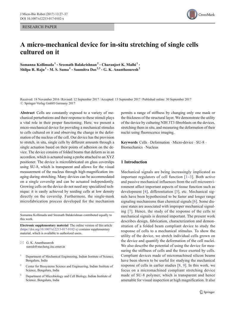
We present here a technique that meets the aforemen-tioned requirements by proposing a microfabricated de-vice made using folded beams. This device can performuniaxial stretching of multiple individual cells with mini-mal substrate interaction. Our design consists of foldedbeams made of SU-8 (Figs. 1 and 2). The gap betweenthe beams is less than the size of a cell, which is about15 μm. When cells are seeded onto the device at suffi-ciently low density, we get individual cells attached ran-domly between the beams (Fig. 1). By pulling on thebeams with a probe (Fig. 3), we can stretch these cells.The stretch on the cells depends on their location on thedevice. The cells toward the centre of the beams getstretched more than those at the ends of the beams.Hence, with a single actuation, we can observe the re-sponse to varying stretch on the cells (Fig. 1). These de-vices are fabricated on coverslips and hence are amenable
for high-magnification live imaging. Furthermore, eachdevice can be actuated independently without disturbingthe cells on the other devices. The total footprint of asingle device is approximately 1 mm × 0.5 mm and,hence, many (more than hundred) such devices can bemicrofabricated on a single coverslip. The devices arefabricated using a simple two-layer process without theneed for al ignment. I t involves a base layer ofOmniCoat that is preferentially removed from below thebeams by a timed etch. Our stretchers have relatively easyfabrication (one mask, two-layer process without align-ment), cell attachment (low density blanket cell seeding),and a simple actuation mechanism (micropipettesmounted on XYZ positioners). Since the stiffness of afolded beam mechanism varies by (1/l3) and w3 [27]where l and w are the length and width of the beamsrespectively, the stiffness of the device can be tuned basedon the cell under study. Table 1 shows a comparison ofthe attributes the earlier mentioned techniques with thetechnique we have developed.
In a demonstrative study using our device, we observedthe deformation of the nuclei of NIH 3T3 cells by fluores-cence imaging during stretching. The shape of the nucleushas been shown to affect fundamental aspects of cell func-tion such as gene expression and in turn protein expression[28, 29]. It is hypothesized that the nucleus plays an im-portant role in mechanotransduction [30]. The forces onthe cell membrane are transferred to the nucleus throughthe cytoskeleton [29]. The transmitted forces change theshape of the nucleus. Due to the change in the nuclearshape, the genes bound to lamin on the periphery of thenucleus may get dislodged leading to altered transcription[28]. Further, the mechanical properties of the nuclei havebeen shown to change from a positive Poisson’s ratio to anegative Poisson’s ratio as the cell exits pluripotency [31].Hence, a device to deform a cell and observe the responseof the nucleus to this stimulus will be valuable in under-standing the mechanotransduction process.
In the following sections we describe the design of thedevice, the fabrication process, measurement of the stiff-ness of the device, comparison with finite element simula-tions, cell-seeding, culture, in situ stretching, and measur-ing the mechanical response.
2 Material and methods
2.1 Design of the device
The design was primarily driven by experimental conve-nience. Thus, it was decided to fabricate the device on cover-slips to allow high-magnification imaging from underneath.We chose SU-8 for fabricating the device because it is
28 J Micro-Bio Robot (2017) 13:27–37
transparent, elastic, and non-toxic to cells [32]. A folded beamsuspension design was adapted for the device. The spacingbetween the folded beams was chosen based on the dimen-sions of cells in suspension. The spacing had to be such thatsuspended cells could sit between the beams without touchingthe coverslip below. The beams had to be sufficiently wide forthe cells to attach. In its native environment the stiffness of thecell-substrate is comparable to the stiffness of the cell [33] andhence we wanted the cell stretcher to have stiffness compara-ble to that of the cell. With comparable stiffness, the cells areable to deform the mechanism and this can be used to computethe forces exerted by them [34]. Hence, the length and out-of-plane thickness of the folded beams was chosen such that thestiffness of the mechanism is of the same order of magnitudeas compared to the stiffness of the cells. One end of the devicewas connected to a large pad to ensure firm adhesion to thesurface. By using a timed development we could ensure pref-erential release of the beams while the pads remained attachedto the coverslip. The device had a triangular frame at the otherend to allow for actuation using a probe without disturbing thecells on the beams.
Previous studies have reported a modulus of elasticity ofaround 6 kPa for fibroblasts [33] and human MesenchymalStem Cells [35] and 2–5 kPa for human hepatocellularcarcinoma [36]. For a cell having a modulus of elasticityin the 6 kPa range, this translates to a stiffness of approx-imately 0.024 N/m (assuming the cell to be a homogeneouscuboid of 20 × 10 × 2 μm and stretched along the 10 μmedge). In an earlier work, it was observed that for mecha-nisms with in-plane stiffness of around 0.042 N/m, themechanisms tend to deform out-of-plane due to buoyancy[37] and are not amenable for easy in-situ experimentation.Hence, we wanted to design the mechanism with stiffnessan order of magnitude greater than cell stiffness. Further,the dimensions of the device were constrained by the sizeof the cells, the material chosen, and the practical limits ofthe microfabrication process. The in-plane width of thebeams was taken as 5 μm, which is a practical lower limitin our fabrication process. By choosing the beam length of210 μm, an out-of-plane thickness of 1.5 μm, and by usingSU-8 (Young’s modulus = 4.02 GPa [38]), simulations inCOMSOL gave a stiffness of 0.178 N/m per folded beam,
Fig. 1 Schematic representationof cells growing on the SU-8(grey) cell stretcher before (a) andafter actuation (b). The insetsshow the deformation of a cell(green) and its nucleus (blue)attached between the beams of thedevice
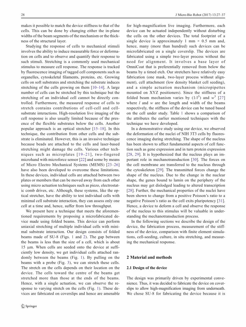
Fig. 2 SEM images of thefabricated stretching mechanisms.The red arrows point to the padregions which will remainattached to the coverslip. Scalebar = 500 μm
J Micro-Bio Robot (2017) 13:27–37 29
which meets our requirements. Table 2 shows the dimen-sions of the designed and fabricated device. Three suchfolded beams were connected in series by a 70 μm widerectangular block. The rectangular block had to be wideenough so that it is relatively rigid compared to the beams.An XYZ positioner was used to actuate the devices. Byhaving three folded beams in series, the minimum defor-mation that can be given to a cell is reduced to a third of theresolution of the XYZ positioner. Since three folded beamsare connected in series, the stiffness of the device is a thirdof the stiffness of the folded beam (0.059 N/m).
The gap between the beams and that between twofolded beams was taken as 10 μm, which is lower thanthe diameter of a cell in suspension (approximately 15–20 μm). When cells are seeded onto the device, the cellsrest on top of the beams since their diameter is larger thanthe gap between the beams. It is likely that in some cases,
the cells squeeze into the gaps between the beams as theygrow. Indeed, it was observed in some cells but not all.Those cells that only spread laterally and not into the gapare considered for measurement.
The shape of the triangular frame used for actuation isequilateral and the length of the side of the outer triangle is400 μm and that of the inner triangle is 225 μm. The size ofthe triangle was chosen such that a stiff probe (around 30–50 μm in diameter) can comfortably fit inside the inner trian-gle and safely actuate the device.
2.2 Microfabrication
Glass coverslips (22 mm circular or square) were cleanedby piranha cleaning. A thin layer for OmniCoat(Microchem) was formed by spin-coating at 3000 rpm for40 s followed by a curing bake at 200 °C for one minute.
Table 1 Comparison of theattributes of techniques used formeasuring mechanical propertiesof cells
Technique Membranestretching [10–14]
Micro-plates[17, 18]
Opticalstretcher [16]
MEMSdevices [21]
ThisdeviceAttribute
High magnification ininverted microscopy
No Yes Yes No Yes
Compartmentalization No No Yes Yes Yes
Device simplicity Yes No No No Yes
Scalability Yes No No Yes Yes
Ease of stiffness matching High Medium High Medium High
Force measurement No Yes Yes Yes Yes
Manipulate single/multiplecells
Yes Yes No Yes Yes
Ease of use High Moderate High High High
Material used for probing PDMS Glass Glass Polysilicon Su-8
Ease of fabrication High High Low Medium High
High magnification microscopy implies the ability to use high numerical aperture (> 1) objectives during cellmanipulation. Compartmentalization implies the ability to only apply mechanical stimuli on the cell of choice.Design simplicity implies the difficulty in building a working setup from scratch. Scalability implies the ability tomass produce the technique. Force measurement implies the ability to use the technique to measure the forcesexerted by cells. Manipulate single/multiple cells implies the ability to apply a mechanical stimuli to either a singleor multiple cells. Ease of use implies the amount of training required to utilize the fabricated device to applymechanical stimulation on cells. Material used for probing denotes the material of the main part of the techniqueused for mechanically stimulating cells
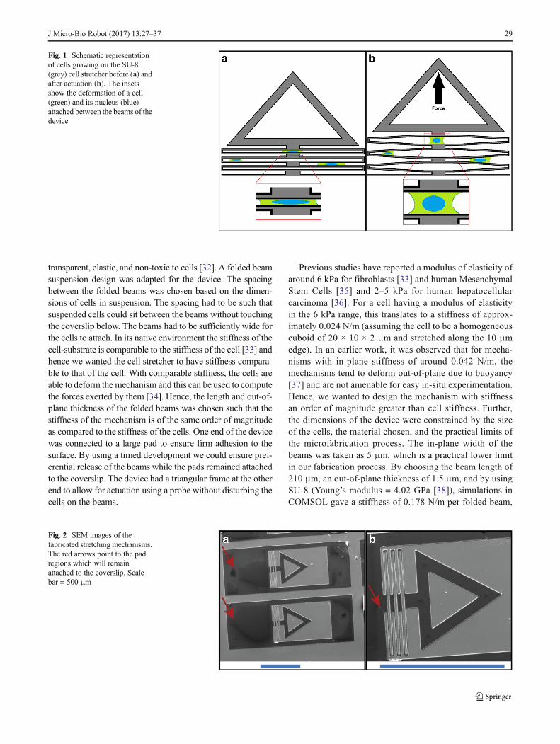
Fig 3 Bright field images of a fabricated mechanism at rest (a) and being deformed (b, c). The red arrow in each image shows the tip of the micropipettebeing used for actuation. Scale bar: 200 μm
30 J Micro-Bio Robot (2017) 13:27–37
Following this, a 1.5 μm thick layer of SU-8 2002(Microchem), was created by spinning at 3000 rpm forone minute. The SU-8 was pre-baked at 95 °C for onemin followed by UV exposure at an energy density of35 mJ/cm2. A post-exposure bake at 95 °C of 2 min wasdone followed by development for 15 min in SU-8 devel-oper (Microchem). The coverslip was then dipped in ace-tone to quench the developing solution and then dipped inOminCoat developer (MF-26A) for 2–3 s to only releasethe beams and the triangular regions of the device and notthe pads. Since the dimensions of the triangular region andthe beams are lower than that of the pad regions theseregions will release faster than the pad regions. We con-ducted timed trials until we could get only the regions weneeded released. The Omni Coat developer was quenchedin DI water and the coverslips were allowed to rest and dryto remove all the water. A schematic representation of thefabrication protocol has been included as Online Resource1.
2.3 Device characterization
The dimensions of the device were obtained using aScanning Electron Microscope (SEM) and the thicknesswas obtained using an optical profilometer (Veeco,WYKO NT1100).
To determine the in-plane stiffness of the device, weused an optical fibre-based force transducer [39]. The forcetransducer consists of a thin optical fibre (diameter 22 μm)of length 9.5 mm. The fibre is held vertical and one end ofthe fibre is firmly held by a clamp while the other end isplaced inside the triangular frame of the device. The deviceas well as the optical fibre and clamp assembly are kept ontop an optical microscope. The clamp is pulled horizontallyby a piezo actuator and the displacement of the clamp isnoted. A laser is passed through the optical fibre. The dis-placement of the laser spot emitted at the tip is recordedand measured through the microscope using a position sen-sitive photo detector with a resolution of 35 nm. The dif-ference between the displacements of the piezo actuatorand the end on the device gives the deformation of the
optical fibre. The force exerted on the device is calculatedfrom the deformation of the optical fibre. For these dimen-sions of the optical fiber, the transducer had a force reso-lution of 0.805 nN. The displacement of the device is equalto the displacement of the laser spot. The force vs. dis-placement curves for three devices were obtained. The stiff-ness was calculated as the slope of a linear fit to this data.
Using the dimensions from the SEM and profilometer, aCAD model of the fabricated device was created inSolidWorks (www.solidworks.com) and analyzed inCOMSOL (www.comsol.com). The material properties ofSU-8 were obtained from the literature [26]. The end of thedevice attached to the pads was assumed to be completelyfixed and a force was applied at the apex point of thetriangle. The geometry was meshed with tetrahedral ele-ments. The displacement was interpolated from the nodesof the mesh using a quadratic scheme.
2.4 Cell culture
NIH 3T3 fibroblasts cells (ATCC R CRL_1658TM) wereused for experiments. The cell lines were cultured in T25flasks (NEST-25 cm2 cell culture flask, canted neck) inhigh glucose Dulbecco’s Modified Eagle Medium (SigmaAldrich, Cat. No. D5648-1 l) with 10% fetal bovine serum(Origin: South America, Gibco, Invitrogen, Ref-10270-106). The cells were cultured in an incubator maintainedat 37 °C and 5% CO2. The device was coated with 20 μg/mL fibronectin (Sigma Aldrich, Cat. No. F2006) for anhour before seeding cells for the experiment. Cells weretrypsinized using Trypsin-EDTA solution (Sigma Aldrich,Cat. No. T3924), seeded on the devices at a concentrationwhere individual cells attach on the devices and allowedto grow for 12 h before experiments were conducted.
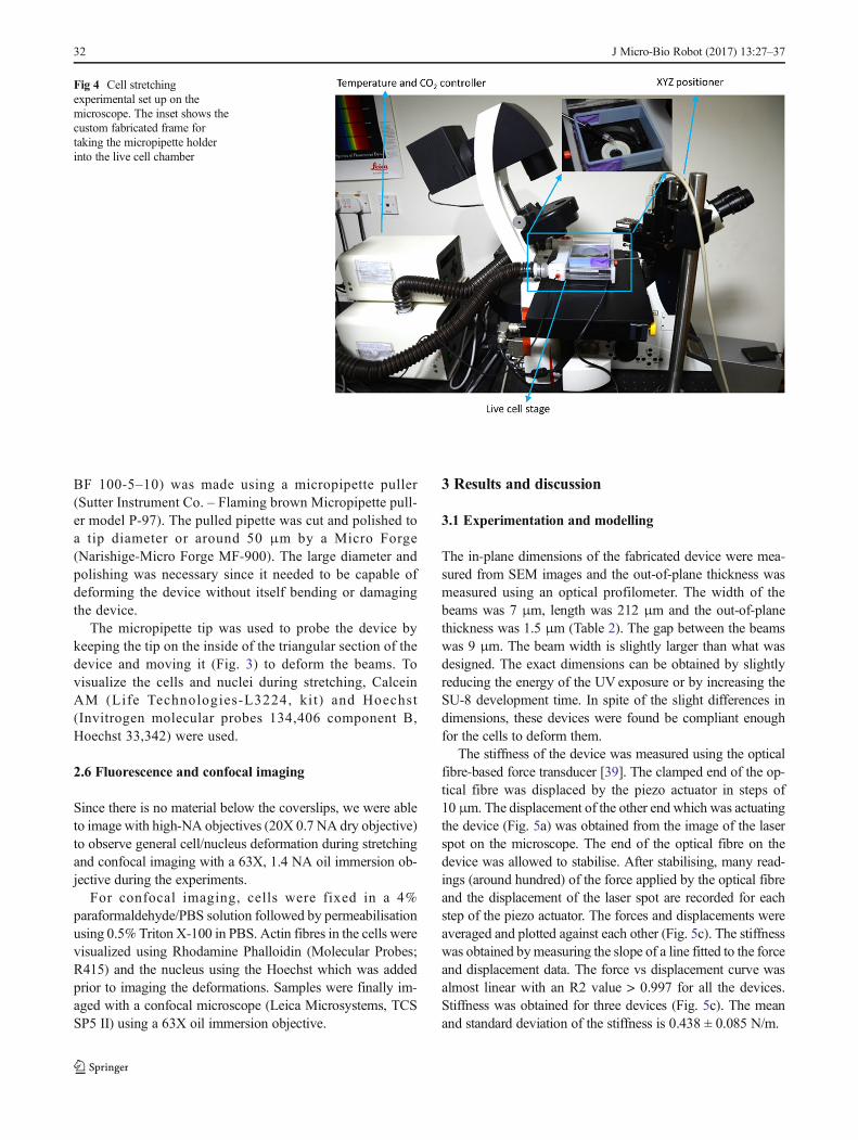
2.5 Cell stretching
The fabricated devices were sterilized under UV in a bio-safety hood prior to cell seeding. For ease of experiments,the coverslips were attached to custom-fabricated punchedPetri dishes. The experiments were conducted on a fullymotorized Leica DMI 6000 B, inverted, fluorescence mi-croscope (Fig. 4) with a live cell stage that maintained thesamples at 37 °C, 5% CO2 and 90% humidity during theexperiment. A custom frame was designed and fabricatedusing a biocompatible material on a 3D printer (ObjetConnex 260). It allows the micropipette holder to enterthe live cell chamber without loss of heat and CO2. Ithad two slots cut into it and the slots were covered by aslit rubber sheet which allowed the pipette holder inside.We used MP-285 (Sutter Instrument Co.), which gives us amovement resolution of 40 nm. A glass micropipette(Borosilicate glass with filament OD 1 mm, ID 0.50 mm,
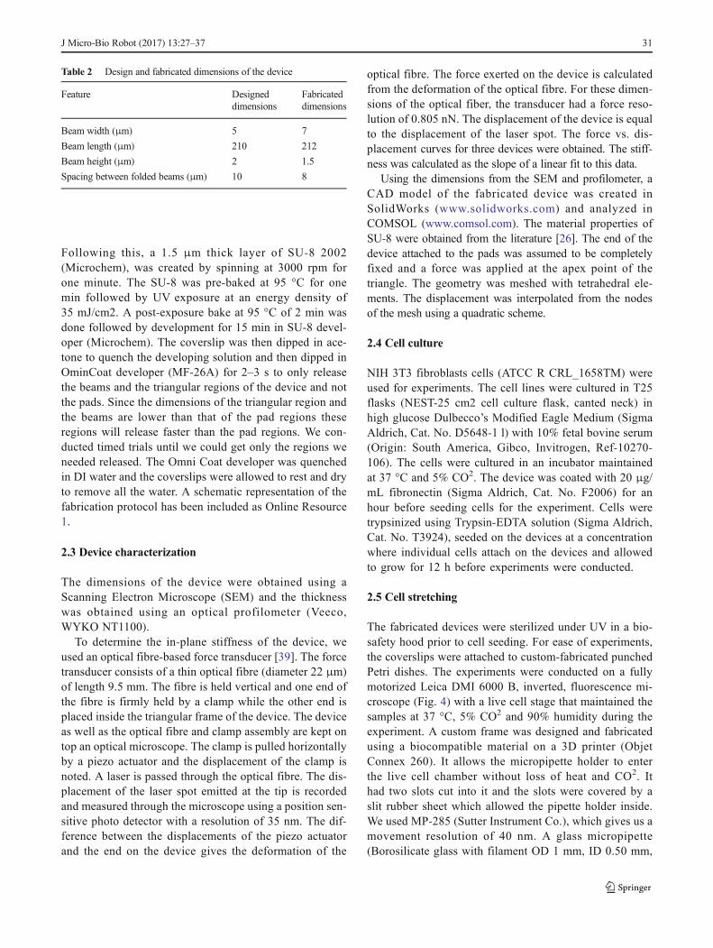
Table 2 Design and fabricated dimensions of the device
Feature Designeddimensions
Fabricateddimensions
Beam width (μm) 5 7
Beam length (μm) 210 212
Beam height (μm) 2 1.5
Spacing between folded beams (μm) 10 8
J Micro-Bio Robot (2017) 13:27–37 31
BF 100-5–10) was made using a micropipette puller(Sutter Instrument Co. – Flaming brown Micropipette pull-er model P-97). The pulled pipette was cut and polished toa tip diameter or around 50 μm by a Micro Forge(Narishige-Micro Forge MF-900). The large diameter andpolishing was necessary since it needed to be capable ofdeforming the device without itself bending or damagingthe device.
The micropipette tip was used to probe the device bykeeping the tip on the inside of the triangular section of thedevice and moving it (Fig. 3) to deform the beams. Tovisualize the cells and nuclei during stretching, CalceinAM (Life Technologies-L3224, ki t) and Hoechst(Invitrogen molecular probes 134,406 component B,Hoechst 33,342) were used.
2.6 Fluorescence and confocal imaging
Since there is no material below the coverslips, we were ableto image with high-NA objectives (20X 0.7 NA dry objective)to observe general cell/nucleus deformation during stretchingand confocal imaging with a 63X, 1.4 NA oil immersion ob-jective during the experiments.
For confocal imaging, cells were fixed in a 4%paraformaldehyde/PBS solution followed by permeabilisationusing 0.5% Triton X-100 in PBS. Actin fibres in the cells werevisualized using Rhodamine Phalloidin (Molecular Probes;R415) and the nucleus using the Hoechst which was addedprior to imaging the deformations. Samples were finally im-aged with a confocal microscope (Leica Microsystems, TCSSP5 II) using a 63X oil immersion objective.
3 Results and discussion
3.1 Experimentation and modelling
The in-plane dimensions of the fabricated device were mea-sured from SEM images and the out-of-plane thickness wasmeasured using an optical profilometer. The width of thebeams was 7 μm, length was 212 μm and the out-of-planethickness was 1.5 μm (Table 2). The gap between the beamswas 9 μm. The beam width is slightly larger than what wasdesigned. The exact dimensions can be obtained by slightlyreducing the energy of the UV exposure or by increasing theSU-8 development time. In spite of the slight differences indimensions, these devices were found be compliant enoughfor the cells to deform them.
The stiffness of the device was measured using the opticalfibre-based force transducer [39]. The clamped end of the op-tical fibre was displaced by the piezo actuator in steps of10 μm. The displacement of the other end which was actuatingthe device (Fig. 5a) was obtained from the image of the laserspot on the microscope. The end of the optical fibre on thedevice was allowed to stabilise. After stabilising, many read-ings (around hundred) of the force applied by the optical fibreand the displacement of the laser spot are recorded for eachstep of the piezo actuator. The forces and displacements wereaveraged and plotted against each other (Fig. 5c). The stiffnesswas obtained bymeasuring the slope of a line fitted to the forceand displacement data. The force vs displacement curve wasalmost linear with an R2 value > 0.997 for all the devices.Stiffness was obtained for three devices (Fig. 5c). The meanand standard deviation of the stiffness is 0.438 ± 0.085 N/m.
Fig 4 Cell stretchingexperimental set up on themicroscope. The inset shows thecustom fabricated frame fortaking the micropipette holderinto the live cell chamber
32 J Micro-Bio Robot (2017) 13:27–37
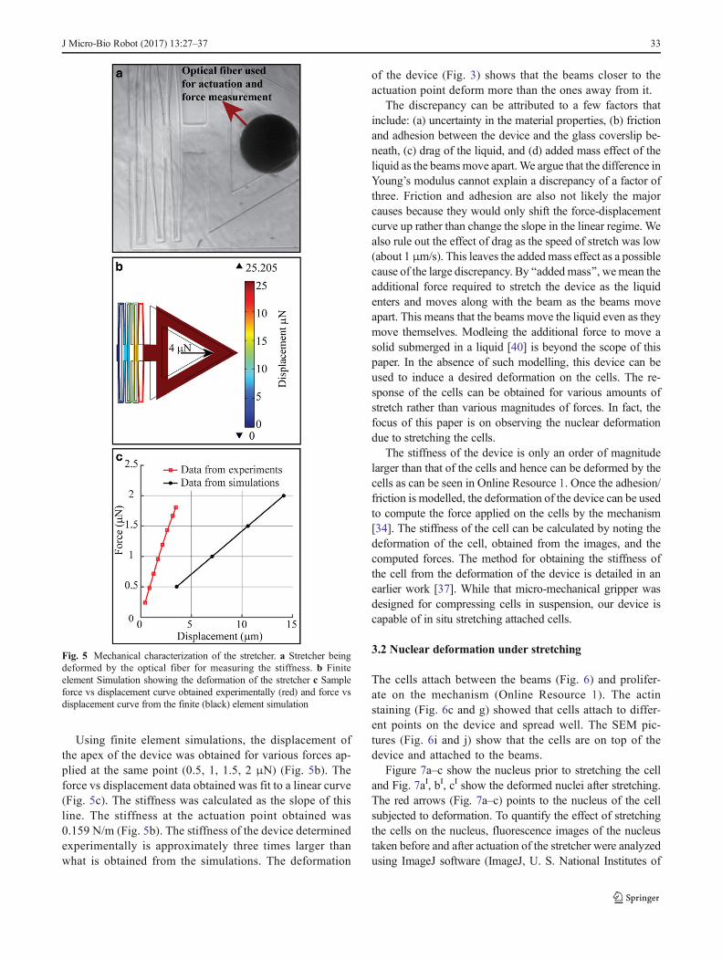
Using finite element simulations, the displacement ofthe apex of the device was obtained for various forces ap-plied at the same point (0.5, 1, 1.5, 2 μN) (Fig. 5b). Theforce vs displacement data obtained was fit to a linear curve(Fig. 5c). The stiffness was calculated as the slope of thisline. The stiffness at the actuation point obtained was0.159 N/m (Fig. 5b). The stiffness of the device determinedexperimentally is approximately three times larger thanwhat is obtained from the simulations. The deformation
of the device (Fig. 3) shows that the beams closer to theactuation point deform more than the ones away from it.
The discrepancy can be attributed to a few factors thatinclude: (a) uncertainty in the material properties, (b) frictionand adhesion between the device and the glass coverslip be-neath, (c) drag of the liquid, and (d) added mass effect of theliquid as the beamsmove apart.We argue that the difference inYoung’s modulus cannot explain a discrepancy of a factor ofthree. Friction and adhesion are also not likely the majorcauses because they would only shift the force-displacementcurve up rather than change the slope in the linear regime. Wealso rule out the effect of drag as the speed of stretch was low(about 1 μm/s). This leaves the added mass effect as a possiblecause of the large discrepancy. By Badded mass^, wemean theadditional force required to stretch the device as the liquidenters and moves along with the beam as the beams moveapart. This means that the beams move the liquid even as theymove themselves. Modleing the additional force to move asolid submerged in a liquid [40] is beyond the scope of thispaper. In the absence of such modelling, this device can beused to induce a desired deformation on the cells. The re-sponse of the cells can be obtained for various amounts ofstretch rather than various magnitudes of forces. In fact, thefocus of this paper is on observing the nuclear deformationdue to stretching the cells.
The stiffness of the device is only an order of magnitudelarger than that of the cells and hence can be deformed by thecells as can be seen in Online Resource 1. Once the adhesion/friction is modelled, the deformation of the device can be usedto compute the force applied on the cells by the mechanism[34]. The stiffness of the cell can be calculated by noting thedeformation of the cell, obtained from the images, and thecomputed forces. The method for obtaining the stiffness ofthe cell from the deformation of the device is detailed in anearlier work [37]. While that micro-mechanical gripper wasdesigned for compressing cells in suspension, our device iscapable of in situ stretching attached cells.
3.2 Nuclear deformation under stretching
The cells attach between the beams (Fig. 6) and prolifer-ate on the mechanism (Online Resource 1). The actinstaining (Fig. 6c and g) showed that cells attach to differ-ent points on the device and spread well. The SEM pic-tures (Fig. 6i and j) show that the cells are on top of thedevice and attached to the beams.
Figure 7a–c show the nucleus prior to stretching the celland Fig. 7aI, bI, cI show the deformed nuclei after stretching.The red arrows (Fig. 7a–c) points to the nucleus of the cellsubjected to deformation. To quantify the effect of stretchingthe cells on the nucleus, fluorescence images of the nucleustaken before and after actuation of the stretcher were analyzedusing ImageJ software (ImageJ, U. S. National Institutes of
Fig. 5 Mechanical characterization of the stretcher. a Stretcher beingdeformed by the optical fiber for measuring the stiffness. b Finiteelement Simulation showing the deformation of the stretcher c Sampleforce vs displacement curve obtained experimentally (red) and force vsdisplacement curve from the finite (black) element simulation
J Micro-Bio Robot (2017) 13:27–37 33
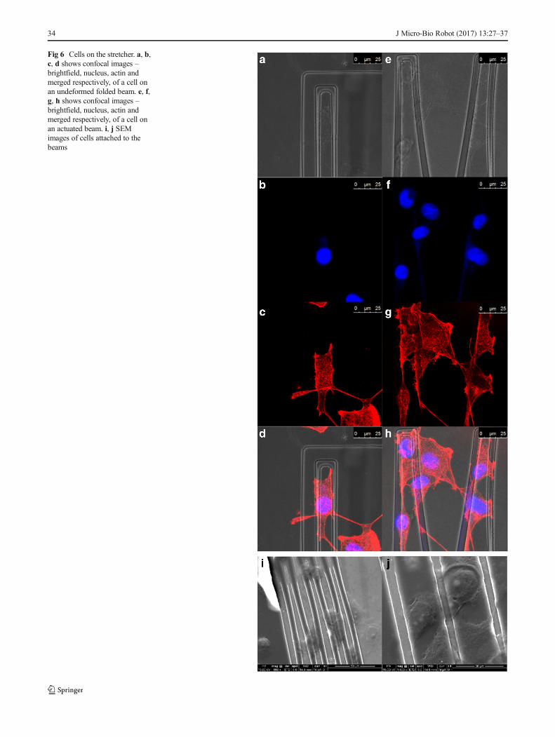
Fig 6 Cells on the stretcher. a, b,c, d shows confocal images –brightfield, nucleus, actin andmerged respectively, of a cell onan undeformed folded beam. e, f,g, h shows confocal images –brightfield, nucleus, actin andmerged respectively, of a cell onan actuated beam. i, j SEMimages of cells attached to thebeams
34 J Micro-Bio Robot (2017) 13:27–37
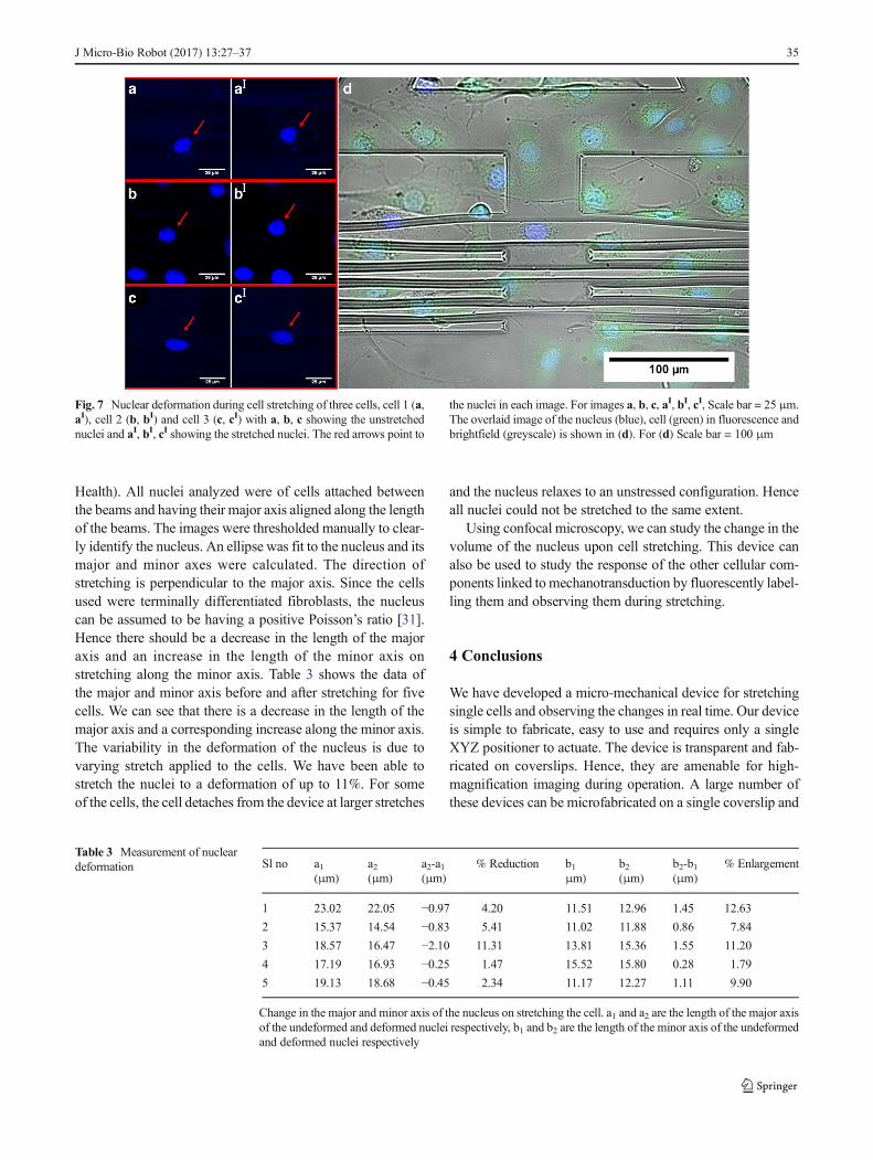
Health). All nuclei analyzed were of cells attached betweenthe beams and having their major axis aligned along the lengthof the beams. The images were thresholded manually to clear-ly identify the nucleus. An ellipse was fit to the nucleus and itsmajor and minor axes were calculated. The direction ofstretching is perpendicular to the major axis. Since the cellsused were terminally differentiated fibroblasts, the nucleuscan be assumed to be having a positive Poisson’s ratio [31].Hence there should be a decrease in the length of the majoraxis and an increase in the length of the minor axis onstretching along the minor axis. Table 3 shows the data ofthe major and minor axis before and after stretching for fivecells. We can see that there is a decrease in the length of themajor axis and a corresponding increase along the minor axis.The variability in the deformation of the nucleus is due tovarying stretch applied to the cells. We have been able tostretch the nuclei to a deformation of up to 11%. For someof the cells, the cell detaches from the device at larger stretches
and the nucleus relaxes to an unstressed configuration. Henceall nuclei could not be stretched to the same extent.
Using confocal microscopy, we can study the change in thevolume of the nucleus upon cell stretching. This device canalso be used to study the response of the other cellular com-ponents linked tomechanotransduction by fluorescently label-ling them and observing them during stretching.
4 Conclusions
We have developed a micro-mechanical device for stretchingsingle cells and observing the changes in real time. Our deviceis simple to fabricate, easy to use and requires only a singleXYZ positioner to actuate. The device is transparent and fab-ricated on coverslips. Hence, they are amenable for high-magnification imaging during operation. A large number ofthese devices can be microfabricated on a single coverslip and
Fig. 7 Nuclear deformation during cell stretching of three cells, cell 1 (a,aI), cell 2 (b, bI) and cell 3 (c, cI) with a, b, c showing the unstretchednuclei and aI, bI, cI showing the stretched nuclei. The red arrows point to
the nuclei in each image. For images a, b, c, aI, bI, cI, Scale bar = 25 μm.The overlaid image of the nucleus (blue), cell (green) in fluorescence andbrightfield (greyscale) is shown in (d). For (d) Scale bar = 100 μm
Table 3 Measurement of nucleardeformation Sl no a1
(μm)a2(μm)
a2-a1(μm)
% Reduction b1μm)
b2(μm)
b2-b1(μm)
% Enlargement
1 23.02 22.05 −0.97 4.20 11.51 12.96 1.45 12.63
2 15.37 14.54 −0.83 5.41 11.02 11.88 0.86 7.84
3 18.57 16.47 −2.10 11.31 13.81 15.36 1.55 11.20
4 17.19 16.93 −0.25 1.47 15.52 15.80 0.28 1.79
5 19.13 18.68 −0.45 2.34 11.17 12.27 1.11 9.90
Change in the major and minor axis of the nucleus on stretching the cell. a1 and a2 are the length of the major axisof the undeformed and deformed nuclei respectively, b1 and b2 are the length of the minor axis of the undeformedand deformed nuclei respectively
J Micro-Bio Robot (2017) 13:27–37 35
independently actuated. Stretching cells on one of the devicesdoes not disturb the cells on others. This allows for multipleexperiments such as different stretches, stretch rates, etc. to beperformed on a single coverslip. Furthermore, we can adjustthe stiffness of the device by varying in-plane widths of beamsegments or the thickness of the structural layer.
Attachment of the cells on the device is accomplished bycoating the entire coverslip with Extra Cellular Matrix (ECM)proteins and seeding cells on it. We do not need to pattern theECM proteins nor place the cells individually on the device.By fluorescent labelling of specific cell components, we canobserve their response to mechanical stimuli. This device canbe a simple and useful tool to study the effects of mechanicalstimuli on cells. As a demonstration, we have cultured NIH3T3 fibroblasts on the device, stretched them in situ, and mea-sured the deformation of the nucleus as the cell was stretched.We show that cells are capable of deforming the device inOnline Resource 1 suggesting that this device can be used tomeasure the forces exerted by cells. We accept that there is apossibility that the cells attach to the surface of the glass cov-erslip. To avoid this, in future, we plan to have the samemechanism as an overhanging structure and eliminate anysurface interaction.
Acknowledgements Authors would like to acknowledge Prof. PramodPullarkat and his student Sushil Dubey, Raman Research Institute forhelping with the stiffness measurements and Anitha Shiva, Center forNano Science and Engineering, Indian Institute of Science for helpingwith the microfabrication and Gowri Balachandran for helping take theSEM images of the device. This work was supported by theBBioengineering and Biodesign Initiative^ grant from the Departmentof Biotechnology, Government of India.
References
1. Wang H, Dembo M, Wang Y et al (2000) Substrate flexibility reg-ulates growth and apoptosis of normal but not transformed cells.Am J Physiol Cell Phys 279(5):1345–1350
2. Paszek MJ, Zahir N, Johnson KR et al (2005) Tensional homeosta-sis and the malignant phenotype. Cancer Cell 8:241–254. https://doi.org/10.1016/j.ccr.2005.08.010
3. Discher DE, Janmey P, Wang Y-L (2005) Tissue cells feel andrespond to the stiffness of their substrate. Science 310:1139–1143.https://doi.org/10.1126/science.1116995
4. Farge E (2003) Mechanical induction of twist in the drosophilaforegut / stomodeal primordium. Curr Biol 13:1365–1377. https://doi.org/10.1016/S0960-9822(03)00576-1
5. Engler AJ, Sen S, Sweeney HL, Discher DE (2006) Matrix elastic-ity directs stem cell lineage specification. Cell 126:677–689. https://doi.org/10.1016/j.cell.2006.06.044
6. Wang N, Tytell JD, Ingber DE (2009) Mechanotransduction at adistance: mechanically coupling the extracellular matrix with thenucleus. Nat Rev Mol Cell Biol 10:75–82. https://doi.org/10.1038/nrm2594
7. Suresh S (2007) Biomechanics and biophysics of cancer cells. ActaMater 55:3989–4014. https://doi.org/10.1016/j.actamat.2007.04.022
8. Rajagopalan J, Tofangchi A, Saif MTA (2010) Drosophila neuronsactively regulate axonal tension in vivo. Biophys J 99:3208–3215.https://doi.org/10.1016/j.bpj.2010.09.029
9. Rajagopalan J, Tofangchi A, Saif MTA (2010) Linear high-resolution BioMEMS force sensors with large measurement range.J Microelectromech Syst 19:1380–1389. https://doi.org/10.1109/JMEMS.2010.2076780
10. Potter SM, DeMarse TB (2001) A new approach to neural cellculture for long-term studies. J Neurosci Methods 110:17–24.https://doi.org/10.1016/S0165-0270(01)00412-5
11. Wang JHC, Goldschmidt-Clermont P, Yin FCP (2000) Contractilityaffects stress fiber remodeling and reorientation of endothelial cellssubjected to cyclic mechanical stretching. Ann Biomed Eng 28:1165–1171. https://doi.org/10.1114/1.1317528
12. Moraes C, Chen J-H, Sun Y, Simmons CA (2010) Microfabricatedarrays for high-throughput screening of cellular response to cyclicsubstrate deformation. Lab Chip 10:227–234. https://doi.org/10.1039/b914460a
13. Wang Q, Zhang X, Zhao Y (2013) Micromechanical stimulator forlocalized cell loading: fabrication and strain analysis. J MicromechMicroeng 23:15002. https://doi.org/10.1088/0960-1317/23/1/015002
14. Huang Y, Nguyen NT (2013) A polymeric cell stretching device forreal-time imaging with optical microscopy. Biomed Microdevices15:1043–1054. https://doi.org/10.1007/s10544-013-9796-2
15. Guck J, Ananthakrishnan R, Mahmood H et al (2001) The opticalstretcher: a novel laser tool to micromanipulate cells. Biophys J 81:767–784. https://doi.org/10.1016/S0006-3495(01)75740-2
16. Dao M, Lim CT, Suresh S (2003) Mechanics of the human redblood cell deformed by optical tweezers. J Mech Phys Solids 51:2259–2280. https://doi.org/10.1016/j.jmps.2003.09.019
17. Rørth P (2012) Fellow travellers: emergent properties of collectivecell migration. EMBO Rep 13:984–991. https://doi.org/10.1038/embor.2012.149
18. Sugiura T, Miyoshi H, Nishio T, Honda A (2012) Cell palpationwith an optically trapped particle. J Micro-Nano Mechatronics 7:131–136. https://doi.org/10.1007/s12213-012-0051-3
19. Thoumine O, Ott A, Cardoso O, Meister JJ (1999) Microplates: anew tool for manipulation and mechanical perturbation of individ-ual cells. J Biochem BiophysMethods 39:47–62. https://doi.org/10.1016/S0165-022X(98)00052-9
20. Thoumine O, Ott A (1997) Time scale dependent viscoelastic andcontractile regimes in fibroblasts probed by microplate manipula-tion. J Cell Sci 110:2109–2116
21. Sun Y, Liu X, WangW, Lansdrop BM (2007) Vision-based cellularforce measurement using an elastic microfabricated device. JMicromech Microeng 17:1281–1288
22. Ohara K, Kawakami D, Takubo T et al (2012) Dextrous cell diag-nosis using two-fingered microhand with micro force sensor. JMicro-Nano Mechatronics 7:13–20. https://doi.org/10.1007/s12213-012-0040-6
23. Serrell DB, Law J, Slifka AJ et al (2008) A uniaxial bioMEMSdevice for imaging single cell response during quantitative force-displacement measurements. Biomed Microdevices 10:883–889.https://doi.org/10.1007/s10544-008-9202-7
24. Fior R, Maggiolino S, Lazzarino M, Sbaizero O (2011) A newtransparent bio-MEMS for uni-axial single cell stretching.Microsyst Technol 17:1581–1587. https://doi.org/10.1007/s00542-011-1325-8
25. Antoniolli F, Maggiolino S, Scuor N et al (2014) A novel MEMSdevice for the multidirectional mechanical stimulation of singlecells: preliminary results. Mech Mach Theory 78:131–140.https://doi.org/10.1016/j.mechmachtheory.2014.03.009
26. Sato K, Kamada S, Minami K (2010) Development ofmicrostretching device to evaluate cell membrane strain field
36 J Micro-Bio Robot (2017) 13:27–37

around sensing point ofmechanical stimuli. Int JMech Sci 52:251–256. https://doi.org/10.1016/j.ijmecsci.2009.09.021
27. Wai-Chi W, Azid AA, Majlis BY (2010) Formulation of stiffnessconstant and effective mass for a folded beam. Arch Mech 62:405–418
28. Fedorchak GR, Kaminski A, Lammerding J (2014) Cellularmechanosensing: getting to the nucleus of it all. Prog BiophysMol Biol 115:76–92. https://doi.org/10.1016/j.pbiomolbio.2014.06.009
29. Dahl KN, Ribeiro AJS, Lammerding J (2009) Nuclear shape, me-chanics, and mechanotransduction. Circ Res 102:1307–1318.https://doi.org/10.1161/CIRCRESAHA.108.173989
30. Isermann P, Lammerding J (2013) Nuclear mechanics andmechanotransduction in health and disease. Curr Biol. https://doi.org/10.1016/j.cub.2013.11.009
31. Pagliara S, Franze K, Mcclain CR et al (2014) Transition frompluripotency in embryonic stem cells distinguished by an auxeticnucleus. Nat Mater 13:638–644. https://doi.org/10.1038/nmat3943.
32. Xue P, Bao J, Chuah YJ et al (2014) Protein covalently conjugatedSU-8 surface for the enhancement of mesenchymal stem cell adhe-sion and proliferation. Langmuir 30:3110–3117. https://doi.org/10.1021/la500048z
33. Solon J, Levental I, Sengupta K et al (2007) Fibroblast adaptationand stiffnessmatching to soft elastic substrates. Biophys J 93:4453–4461. https://doi.org/10.1529/biophysj.106.101386
34. Reddy AN, Ananthasuresh GK (2008) On computing the forcesfrom the noisy displacement data of an elastic body. Int J NumerMethods Eng 76:1645–1677. https://doi.org/10.1002/nme.2373
35. Tee SY, Fu J, Chen CS, Janmey PA (2011) Cell shape and substraterigidity both regulate cell stiffness. Biophys J 100:L25–L27. https://doi.org/10.1016/j.bpj.2010.12.3744
36. Zhu X, Zhang N, Wang Z, Liu X (2016) Investigation of work ofadhesion of biological cell (human hepatocellular carcinoma) byAFM nanoindentation. J Micro-Bio Robot 11:47–55. https://doi.org/10.1007/s12213-016-0089-8
37. Bhargav SDB, Jorapur N, Ananthasuresh GK (2015) Micro-scalecomposite compliant mechanisms for evaluating the bulk stiffnessof MCF-7 cells. Mech Mach Theory 91:258–268. https://doi.org/10.1016/j.mechmachtheory.2015.04.002
38. Lorenz H, Despont M, Fahrni N et al (1997) SU-8: a low-costnegative resist for MEMS. J Micromech Microeng 7:121–121.https://doi.org/10.1088/0960-1317/7/3/010
39. Seshagiri Rao RV, Kalelkar C, Pullarkat PA (2013) Optical fiber-based force transducer for microscale samples. Rev Sci Instrum.https://doi.org/10.1063/1.4824198
40. Dong RG (1978) Effective mass and damping of submerged struc-tures. UCRL-52342, April, Lawrence Livermore Laboratory, U.California, Livermore, CA, USA
J Micro-Bio Robot (2017) 13:27–37 37