Embed Size (px)
Citation preview
Materials and Design 52 (2013) 821–827
Contents lists available at SciVerse ScienceDirect
Materials and Design
journal homepage: www.elsevier .com/locate /matdes
Gradient micro-structured surface layer on aluminum alloy fabricatedby in situ rolling friction stir welding
0261-3069/$ - see front matter Crown Copyright � 2013 Published by Elsevier Ltd. All rights reserved.http://dx.doi.org/10.1016/j.matdes.2013.06.026
⇑ Corresponding author. Tel.: +86 45186413951; fax: +86 45186416186.E-mail address: [email protected] (Y. Huang).
Yongxian Huang ⇑, Long Wan, Shixiong Lv, Huijie Liu, Jicai FengState Key Laboratory of Advanced Welding and Joining, Harbin Institute of Technology, Harbin 150001, People’s Republic of China
a r t i c l e i n f o
Article history:Received 8 April 2013Accepted 11 June 2013Available online 24 June 2013
Keywords:In situ rolling friction stir weldingGradient micro-structureMicrohardnessWear resistanceCorrosion
a b s t r a c t
A gradient micro-structure was formed in the surface layer of 2219 aluminum alloy joint by means ofin situ rolling friction stir welding (IRFSW). The micro-structured surface layer is about 200 lm deep, cor-responding to a gradient change in microhardness from 86.8 to 59.4 HV in the coarse-grained weld nug-get zone (WNZ). Compared with those of the base material, the friction coefficient values are evidentlydecreased and the wear resistance is obviously enhanced on the surface layer. The corrosion currentwas relatively low and corrosion potential value was positive with respect to that of the base material.The second-phase particles in the upper surface layer were much more and smaller than those of the basematerial.
Crown Copyright � 2013 Published by Elsevier Ltd. All rights reserved.
1. Introduction
In most cases, material failures occur on surfaces such as fatiguefracture, fretting fatigue, and wear and corrosion. These failures arevery sensitive to the structure and properties of the material sur-face. To many materials, the low surface hardness and poor wearresistance has restricted their applications in engineering fields[1]. However, optimization of the surface microstructure and prop-erties is an effective approach to enhance the global behavior andservice lifetime of materials [2].
Plastic deformation-induced grain refinement in the submi-crometer or nanometer regimes has been extensively investigatedin various metals and alloys over the past decades, both in bulkforms [3] and in surface layers on bulk materials [4]. Optimizingsurface properties by refining grains in surface layers to the nano-meter scale (referred to as surface nanocrystallization) providesmore promising practical industrial applicability. Surface mechan-ical attrition treatment (SMAT) is a developed technique that caninduce grain refinement into the nanometer regime in the surfacelayer of bulk materials [5]. The SMAT transforms the originalcoarse-grains at the surface material into refined-ones [6]. Thegrains refining mechanisms in SMAT is conducted by the randomand repetitive impact of milling balls to the sample’s surface. Thistechnique has been successfully applied in achieving surface nano-crystallization (SNC) in a variety of materials including pure met-als, alloys and steels [7–10]. Another technique has beendeveloped based on basically the principle of plastic
deformation-induced grain refinement is friction sliding [11].However, these two processes suffer from either low processingefficiencies or limited nano-structured layer thicknesses, or struc-tural inhomogeneity in the surface layer, all of which have hin-dered the widespread application of surface nanocrystallizationtechnologies [12].
In recent years, surface mechanical grinding treatment (SMGT)is developed to synthesize a gradient nano-micro-structure in thesurface layer of bulk metals [12]. The SMGT technique is basedon machining-induced plastic deformation and can achieve surfacemodification by generation of a nano-structured surface layer sothat the overall properties and behavior of the materials are signif-icantly improved. This technique requires only simple proceduresand can be readily applied to engineering materials [12]. Frictionstir processing technique refines the microstructure in the surfacelayer during which a large plastic strain is generated together witha substantial mass flow accompanied by a large, localized temper-ature rise [13]. This results in relatively large grain sizes, typicallyof the order of several hundred nanometers, via dynamic recrystal-lization [14]. FSP has proved to be a viable tool for enhancing themechanical properties of materials, however, the major focus hasbeen upon improving the bulk properties of light metals and theiralloys [15,16].
A surface enhancement technology, Low Plasticity Burnishing(LPB), is also developed to produce a deep layer of highly compres-sive residual stress with a minimum amount of cold working, orplastic deformation [17]. It can provide compression in the surfacelayer of sufficient depth to effectively eliminate the degradation incorrosion/fatigue life attributed to salt pit corrosion [18]. UnlikeLPB, conventional roller and ball burnishing utilize a hard wheel
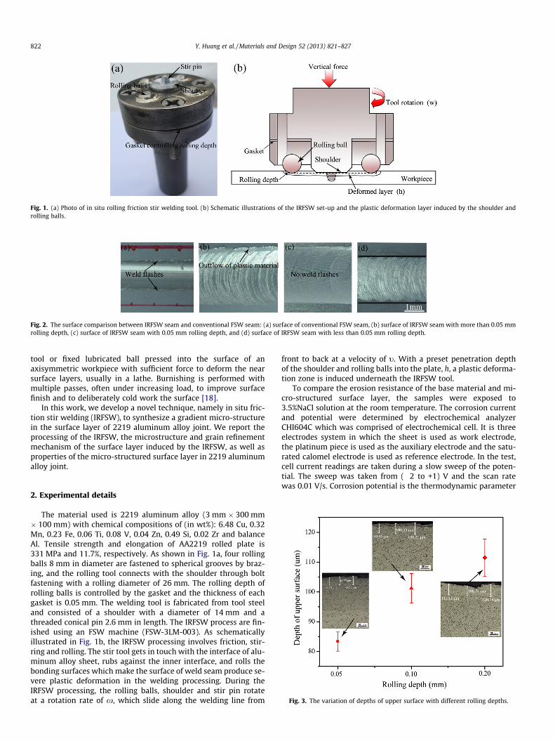
Fig. 1. (a) Photo of in situ rolling friction stir welding tool. (b) Schematic illustrations of the IRFSW set-up and the plastic deformation layer induced by the shoulder androlling balls.
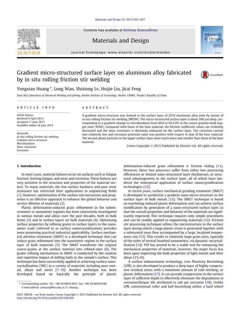
Fig. 2. The surface comparison between IRFSW seam and conventional FSW seam: (a) surface of conventional FSW seam, (b) surface of IRFSW seam with more than 0.05 mmrolling depth, (c) surface of IRFSW seam with 0.05 mm rolling depth, and (d) surface of IRFSW seam with less than 0.05 mm rolling depth.
822 Y. Huang et al. / Materials and Design 52 (2013) 821–827
tool or fixed lubricated ball pressed into the surface of anaxisymmetric workpiece with sufficient force to deform the nearsurface layers, usually in a lathe. Burnishing is performed withmultiple passes, often under increasing load, to improve surfacefinish and to deliberately cold work the surface [18].
In this work, we develop a novel technique, namely in situ fric-tion stir welding (IRFSW), to synthesize a gradient micro-structurein the surface layer of 2219 aluminum alloy joint. We report theprocessing of the IRFSW, the microstructure and grain refinementmechanism of the surface layer induced by the IRFSW, as well asproperties of the micro-structured surface layer in 2219 aluminumalloy joint.
Fig. 3. The variation of depths of upper surface with different rolling depths.
2. Experimental details
The material used is 2219 aluminum alloy (3 mm � 300 mm� 100 mm) with chemical compositions of (in wt%): 6.48 Cu, 0.32Mn, 0.23 Fe, 0.06 Ti, 0.08 V, 0.04 Zn, 0.49 Si, 0.02 Zr and balanceAl. Tensile strength and elongation of AA2219 rolled plate is331 MPa and 11.7%, respectively. As shown in Fig. 1a, four rollingballs 8 mm in diameter are fastened to spherical grooves by braz-ing, and the rolling tool connects with the shoulder through boltfastening with a rolling diameter of 26 mm. The rolling depth ofrolling balls is controlled by the gasket and the thickness of eachgasket is 0.05 mm. The welding tool is fabricated from tool steeland consisted of a shoulder with a diameter of 14 mm and athreaded conical pin 2.6 mm in length. The IRFSW process are fin-ished using an FSW machine (FSW-3LM-003). As schematicallyillustrated in Fig. 1b, the IRFSW processing involves friction, stir-ring and rolling. The stir tool gets in touch with the interface of alu-minum alloy sheet, rubs against the inner interface, and rolls thebonding surfaces which make the surface of weld seam produce se-vere plastic deformation in the welding processing. During theIRFSW processing, the rolling balls, shoulder and stir pin rotateat a rotation rate of x, which slide along the welding line from
front to back at a velocity of t. With a preset penetration depthof the shoulder and rolling balls into the plate, h, a plastic deforma-tion zone is induced underneath the IRFSW tool.
To compare the erosion resistance of the base material and mi-cro-structured surface layer, the samples were exposed to3.5%NaCl solution at the room temperature. The corrosion currentand potential were determined by electrochemical analyzerCHI604C which was comprised of electrochemical cell. It is threeelectrodes system in which the sheet is used as work electrode,the platinum piece is used as the auxiliary electrode and the satu-rated calomel electrode is used as reference electrode. In the test,cell current readings are taken during a slow sweep of the poten-tial. The sweep was taken from (�2 to +1) V and the scan ratewas 0.01 V/s. Corrosion potential is the thermodynamic parameter
Fig. 4. A cross-sectional observation of the IRFSW-processed sample: (a) optical microscope of cross-sectional structure, (b) magnification of the red frame part in a and threedistinct zones: I – upper surface, II – middle surface, III – lower surface, and (c) magnification of the red frame part in b. (For interpretation of the references to colour in thisfigure legend, the reader is referred to the web version of this article.)
Fig. 5. Measured microhardness as a function of depth from the upper surface,middle surface and the lower surface for the IRFSW-processed sample.
Y. Huang et al. / Materials and Design 52 (2013) 821–827 823
which reflects the tendency of material corrosion, and corrosioncurrent belongs to dynamic parameter which can reflect the corro-sion rate.
The microhardness testing is conducted using a Vickers hard-ness testing machine (HX-1000) with a test load of 50 g and anindentation time of 10 s and the microhardness values are takenfrom the cross-section along the thickness direction in the surfacelayer of the joint. Nano-hardness tests were performed by a nano-indenter G200 with a maximum load of 10 g and peak hold time of10 s. The tests of wear resistance are performed on ball-plate fric-tion-wear testing machine (QP-1) produced by Harbin Institute ofTechnology [19], and the specimens were prepared with referenceto ASTM: G115-10. The macrographs of joints are characterized byoptical microscopy (OM, Olympus-MPG3) and the scanning elec-tron microscope (Hitachi-S4700) is employed to capture a detailedview of the feature.
Fig. 6. Variations of: (a) the hardness and (b) elastic moduli between the uppersurface and the base material.
3. Results and discussion
3.1. Effect of welding parameters
From the previous research, we can know the LPB technique of-fers the opportunity to induce a layer of compressive residualstress into the weld surface [17]. In the IRFSW processing, the roll-ing balls are pressed into the sheet for rolling the weld seam. Themost relevant process parameter is rolling depth which determinesthe form of the weld seam [20]. Photo of the surface of the conven-tional FSW seam is presented in Fig. 2a. It shows that the excessiveweld flashes exited on the surface of the weld seam. We can alsosee that a large amount of plastic material is left on the surfacewhen the rolling depth is more than 0.05 mm. The big rolling depth
results in the serious outflow of the plastic material. However, asshown in Fig. 2c, most of the weld flashes are reduced comparedwith those of the conventional FSW, analogous to the LPB tech-nique which can smooth the weld seam, when the rolling depthis 0.05 mm. As the ball rolls over the sheets, the lateral extrusionpressure from rolling object prevents the outflow of the plasticmaterial and helps smooth surface asperities. When the rollingdepth is less than 0.05 mm, the diameter of weld seam is smallerthan that in Fig. 2c, as shown in Fig. 2d. This is because the rollingdepth is so small that the rolling balls cannot keep in touch withthe plates sufficiently. The rolling pressure from the rolling ballsis associated with the quantity of the plastic material that flowsout the original workpiece surface [20]. Taking into account ofthe plunge depth of the shoulder, the optimized rolling depth is0.05 mm.

Fig. 7. Comparisons of the indentation width profiles: (a and b) the indentation width profiles with 100 s function of QP-1 machine and (c and d) the indentation widthprofiles with 200 s function of QP-1 machine.
Fig. 8. Schematic illustration of ball-surface collision.
824 Y. Huang et al. / Materials and Design 52 (2013) 821–827
Fig. 3 shows the variation of depths of upper surface under thecondition that the rolling depth increases. The depth of upper sur-face increases from 83 lm to 111 lm with the increment of rolling
Table 1Four groups of indentation depth values.
Indentation depth (lm)
Based material (100 s) 22.34 25.26Upper surface (100 s) 20.32 11.39Based material (200 s) 24.72 25.55Upper surface (200 s) 18.46 14.98
depth. This is because the rolling depth is associated with rollingpressure from the rolling balls. When the rolling depth increases,the increased rolling pressure makes the depth of upper surfacedeeper.
From our previous studies [20], IRFSW joints show superior ten-sile properties compared to conventional FSW joints. When thetool rotation rate 600 rev min�1, the rolling depth 0.05 mm, andthe plunge depth 0.1 mm is fixed, the tensile strength of optimizedjoint increases 13% and the elongation almost keeps the same com-pared with those of the conventional FSW. It can be attributed tothe rolling balls which make the plastic material flow more fullyand the grain refinement so that tensile strength is improved.
3.2. Microstructure of the surface layer
The cross-sectional structural characterization of the IRFSW-processed sample was carried out on an optical microscope, asshown in Fig. 4. The IRFSW processing parameters are as follows:rotation rate x = 600 rev min�1, welding speed t = 300 mm min�1,the rolling depth 0.05 mm and the plunge depth 0.1 mm. Plasticdeformation is obvious in the surface layer to a depth exceeding200 lm. Three obvious distinct zones (upper surface, middle
Average depth (lm)
29.91 23.49 25.2518.36 12.33 15.6029.91 21.66 25.4620.28 17.87 17.90

Fig. 9. Variations of the friction coefficient for the IRFSW-processed sample and thebase material.
Fig. 10. Potentiodynamic polarization curves of micro-structured surface layer inthe IRFSW-processed sample and the base material.
Y. Huang et al. / Materials and Design 52 (2013) 821–827 825
surface and lower surface) exist in the surface layer of the joint. Inthe top 100 lm, the grains are the smallest in the whole joint,implying that this zone undergoes severe plastic deformation athigh strain rates. It has recently been shown that, after passageof the tool pin, the upper part of the weld undergoes additionaldeformation by the rotating tool shoulder [21]. Excepting that,the upper surface layer of IRFSW-processed sample still goesthrough the sever deformation by rotating rolling balls. The middlelayer undergoes the function of the stir pin and rotating tool shoul-der, however, the lower layer only undergoes the function of thestir pin.
3.3. Hardness results
Fig. 5 shows the microhardness measurement results from theupper, middle and lower surface layers of the IRFSW-processedsample. Microhardness decreases from about 86.8 HV in the topsurface layer to about 59.4 HV in the lower surface layer (thecoarse-grained WNZ). The lower surface layer is directly influencedby the tool pin and is subjected to a high level of plastic deforma-tion and frictional heating. The grains are refined in the lower
surface layer. This refinement is the result of dynamic recrystallisa-tion and combines action of high rate strain and elevated temper-atures [22–24]. However, the upper surface layer is directly underthe rolling tool and is plastically deformed by friction, stirring androlling.
Nano-hardness and elastic modulus across the treated surfacelayer were also measured by using a nanoindenter with a Berko-vich tip. Hardness decreases from about 0.89 GPa in the upper sur-face layer to about 0.78 GPa in the base material (Fig. 6a).According to the conventional machining process to remove mate-rial, severe plastic deformation takes place in the removed layer,analogous to that in equal channel angular pressing (ECAP) [25].Thereby, similar microstructures are obtained in the removedmaterial compared with the ultrafine structure in the ECAP sam-ples [26]. There is plenty of evidence to indicate that a gradientmicrostructure composed of ultrafine was developed in a very thinlayer on the upper surface layer of the IRFSW-processed sample.The elastic moduli values (about 69.1 GPa) of the base materialand the upper surface layer of the IRFSW-processed sample are un-changed, independent of grain size in the present grain size regime,which is consistent with results in the literature [12].
3.4. Friction and wear properties
From the previous investigations [27,28], we can know thatdeformation twinning plays a key role in refining grains to thenano- and micro-meter scale via plastic deformation at high strainrates and low temperatures. Severe plastic deformation takes placein the upper surface layer of the IRFSW-processed joint due to thefriction, stirring and rolling. However, a substantial temperaturerise is unavoidable during conventional machining, which mightbe high enough to induce noticeable recrystallization and evenphase transformation [29]. Owing to the high thermal conductivityof 2219 aluminum alloy, most of the transient temperature rise inthe upper surface layer induced by friction might be rapidly cooledso that the recovery or recrystallization processes in the deformedlayer could be effectively suppressed. Fig. 7 shows comparisons ofthe indentation width profiles of base material and IRFSW-pro-cessed sample. Fig. 7a and b are the indentation width profiles with100 s function of ball-plate friction-wear testing machine (QP-1)and the indentation width (average 781.72 lm) of the base mate-rial is much bigger than that (average 606.43 lm) of the top sur-face layer. Fig. 7c and d are the indentation width profiles ofsamples that undergoes 200 s function of the QP-1 machine andthe indentation width (average 778.64 lm) of the base materialis much bigger than that (average 653.41 lm) of the top surfacelayer.
According to the pythagorean theorem, as well as the indentationwidths (in Fig. 7) and the diameter of the ceramic ball (R = 3 mm), asshown in Fig. 8, we can calculate the indentation depths of the cera-mic ball on the surfaces of base material and IRFSW-processed sam-ple, which is shown in Table 1. Friction and wear propertymeasurements indicated a significant increment of the wear resis-tance in the surface layer with micro-structures after the IRFSW.When base material and IRFSW-processed sample both undergo100 s function of ball-plate friction-wear testing machine (QP-1),the average indentation depth of IRFSW-processed sample is re-duced to 15.60 lm compared with that (25.25 lm) of the base mate-rial. Under the condition of 200 s function of QP-1 machine, theaverage indentation depth of IRFSW-processed sample is reducedto 17.90 lm compared with that (25.46 lm) of the base material.
As shown in Fig. 9, the friction coefficient values of the micro-structured in surface layer of the IRFSW-processed sample are low-er than that for the base material. In this test, the test load was200 g and the rotation speed was 50 rpm. To assure the samesurface finish, we polish the surfaces of the base material and the
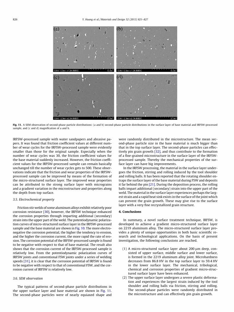
Fig. 11. A SEM observation of second-phase particle distributions: (a and b) second-phase particle distributions in the surface layer of base material and IRFSW-processedsample, and (c and d) magnification of a and b.
826 Y. Huang et al. / Materials and Design 52 (2013) 821–827
IRFSW-processed sample with water sandpapers and abrasive pa-pers. It was found that friction coefficient values at different num-ber of wear cycles for the IRFSW-processed sample were evidentlysmaller than those for the original sample. Especially when thenumber of wear cycles was 30, the friction coefficient values forthe base material suddenly increased. However, the friction coeffi-cient values for the IRFSW-processed sample can remain basicallyunchanged till the number of wear cycles gets to 500. These obser-vations indicate that the friction and wear properties of the IRFSW-processed sample can be improved by means of the formation ofthe micro-structured surface layer. The improved wear propertiescan be attributed to the strong surface layer with micrograinsand a gradient variation in the microstructure and properties alongthe depth from top surface.
3.5. Electrochemical property
Friction stir welds of some aluminum alloys exhibit relatively poorcorrosion resistance [30], however, the IRFSW technique enhancedthe corrosion properties through imparting additional (secondary)strain into the upper part of the weld. The potentiodynamic polariza-tion curves of micro-structured surface layer in the IRFSW-processedsample and the base material are shown in Fig. 10. The more electro-negative the corrosion potential, the higher the tendency to erosion,and the higher the corrosion current, the more rapid the rate of ero-sion. The corrosion potential of the IRFSW-processed sample is foundto be negative with respect to that of base material. The result alsoshows that the corrosion current of the IRFSW-processed sample isrelatively low. From the potentiodynamic polarization curves ofIRFSW joints and conventional FSW joints under a series of weldingspeeds [31], it is clear that the corrosion potential of IRFSW is foundto be negative with respect to that of conventional FSW, and the cor-rosion current of IRFSW is relatively low.
3.6. SEM observation
The typical patterns of second-phase particle distributions inthe upper surface layer and base material are shown in Fig. 11.The second-phase particles were of nearly equiaxed shape and
were randomly distributed in the microstructure. The mean sec-ond-phase particle size in the base material is much bigger thanthat in the top surface layer. The second-phase particles can effec-tively pin grain growth [32], and thus contribute to the formationof a fine-grained microstructure in the surface layer of the IRFSW-processed sample. Thereby the mechanical properties of the sur-face layer can have big improvements.
In the IRFSW processing, the material in the surface layer under-goes the friction, stirring and rolling induced by the tool shoulderand rolling balls. It has been reported that the rotating shoulder en-traps the surface layer of the base material during FSW and depositsit far behind the pin [21]. During the deposition process, the rollingballs impart additional (secondary) strain into the upper part of theweld. The material in the surface layer experiences perhaps the larg-est strain and a rapid heat sink exists in the surface of the joint whichcan prevent the grain growth. These may give rise to the surfacelayer with a very fine recrystallized grain structure.
4. Conclusions
In summary, a novel surface treatment technique, IRFSW, isdeveloped to achieve a gradient micro-structured surface layeron 2219 aluminum alloy. The micro-structured surface layer pro-vides a plenty of unique opportunities in both basic scientific re-search and technological applications. On the basis of presentinvestigation, the following conclusions are reached.
(1) A micro-structured surface layer about 200 lm deep, con-sisted of upper surface, middle surface and lower surface,is formed in the 2219 aluminum alloy joint. Microhardnessdecreases from 86.8 HV in the top surface layer to 59.4 HVin the lower surface layer. The mechanical, tribological,chemical and corrosion properties of gradient micro-struc-tured surface layer have been enhanced.
(2) The upper surface layer undergoes a severe plastic deforma-tion and experiences the largest strain induced by the toolshoulder and rolling balls via friction, stirring and rolling.The second-phase particles were randomly distributed inthe microstructure and can effectively pin grain growth.

Y. Huang et al. / Materials and Design 52 (2013) 821–827 827
(3) The IRFSW shows an alternative approach to effectivelyupgrade the global properties of engineering materials with-out change of the chemical constitution. As the IRFSW issimple and flexible, this new technique is potentially usefulin industrial applications.
Acknowledgements
The work was jointly supported by the National Natural ScienceFoundation of China (No. 50904020), and the Fundamental Re-search Funds for the Central Universities (No. HIT. NSRIF.2012007).
References
[1] Lin Yimin, Jian Lu, Wang Liping, Tao Xu, Xue Qunji. Surface nanocrystallizationby surface mechanical attrition treatment and its effect on structure andproperties of plasma nitrided AISI 321 stainless steel. Acta Mater2006;54:5599–605.
[2] Lu K, Lu J. Nanostructured surface layer on metallic materials induced bysurface mechanical attrition treatment. Mater Sci Eng A 2004;375–377:38–45.
[3] Valiev RZ, Islamgaliev RK, Alexandrov IV. Bulk nanostructured materials fromsevere plastic deformation. Prog Mater Sci 2000;45:103–89.
[4] Lu K, Lu J. Surface nanocrystallization (Snc) of metallic materials-presentationof the concept behind a new approach. J Mater Sci Technol 1999;15:193–7.
[5] Zhang HW, Liu G, Hei ZK, Lu J, Lu K. Surface nanocrystallization of AISI 304stainless steel induced by surface mechanical attrition treatment: I. Structureand property. Acta Mater Sin 2003;39:342–6.
[6] Arifvianto B, Suyitno. Surface roughness and wettability of AISI 316L inducedby surface mechanical attrition treatment with different milling ball diameter.In: 2009 ICICI-BME International Conference on 2009; vols. 23–25. p. 1–4.
[7] Liu G, Lu J, Lu K. Surface nanocrystallization of 316L stainless steel induced byultrasonic shot peening. Mater Sci Eng A 2000;286:91–5.
[8] Liu G, Wang SC, Lou XF, Lu J, Lu K. Low carbon steel with nanostructuredsurface layer induced by high-energy shot peening. Scripta Mater2001;44:1791–5.
[9] Tao NR, Wang ZB, Tong WP, Sui ML, Lu J, Lu K. An investigation of surfacenanocrystallization mechanism in Fe induced by surface mechanical attritiontreatment. Acta Mater 2002;50:4603–16.
[10] Wu X, Tao N, Hong Y, Xu B, Lu J, Lu K. Microstructure and evolution ofmechanically-induced ultrafine grain in surface layer of Al-alloy subjected toUSSP. Acta Mater 2002;50:2075–84.
[11] Hughes DA, Hansen N. Graded nanostructures produced by sliding andexhibiting universal behavior. Phys Rev Lett 2001;87:135503.
[12] Li WL, Tao NR, Lu K. Fabrication of a gradient nano-micro-structured surfacelayer on bulk copper by means of a surface mechanical grinding treatment.Scripta Mater 2008;59:546–9.
[13] Mishra RS, Ma ZY. Friction stir welding and processing. Mater Sci Eng R2005;50:1–78.
[14] Chang CI, Du XH, Huang JC. Producing nanograined microstructure in Mg–Al–Zn alloy by two-step friction stir processing. Scripta Mater 2007;57:209–12.
[15] Karthikeyana L, Senthilkumara VS, Balasubramanianb V, Natarajana S.Mechanical property and microstructural changes during friction stirprocessing of cast aluminum 2285 alloy. Mater Des 2009;30:2237–42.
[16] Grewal HS, Arora HS, Singh H, Agrawal A. Surface modification of hydroturbinesteel using friction stir processing. Appl Surf Sci 2013;268:547–55.
[17] Prevéy P, Cammett J. The influence of surface enhancement by low plasticityburnishing on the corrosion fatigue performance of AA7075-T6. Int J Fatigue2004;26:975–82.
[18] Prevéy P, Mahoney M. Improved fatigue performance of friction stir weldswith low plasticity burnishing: residual stress design and fatigue performanceassessment. Mater Sci Forum 2003;426–432:2933–40.
[19] Z Wu Z, B Tian X, Gui G, Z Gong C, Q Yang S, Chu Paul K, et al. Microstructureand surface properties of chromium-doped diamond-like carbon thin filmsfabricated by high power pulsed magnetron sputtering. Appl Surf Sci2013;276:31–6.
[20] Huang YX, Wan L, Lv SX, Zhang J, Fu GS. In situ rolling friction stir welding forjoining AA2219. Mater Des 2013;50:810–6.
[21] Suhuddin UFHR, Mironov S, Sato YS, Kokawa H, Lee CW. Grain structureevolution during friction-stir welding of AZ31 magnesium alloy. Acta Mater2009;57:5406–18.
[22] Sua JQ, Nelson TW, Sterling CJ. Microstructure evolution during FSW/FSP ofhigh strength aluminum alloys. Mater Sci Eng A 2005;405:277–86.
[23] Barcellona A, Buffa G, Fratini L, Palmeri D. On microstructural phenomenaoccurring in friction stir welding of aluminum alloys. J Mater Process Technol2006;177:340–3.
[24] Ouyang J, Yarrapareddy E, Kovacevic R. Microstructural evolution in thefriction stir welded 6061 aluminum alloy (T6-temper condition) to copper. JMater Process Technol 2006;172:110–22.
[25] Shankar MR, Rao BC, Lee S, Chandrasekar S, King AH, Compton WD. Severeplastic deformation (SPD) of titanium at near-ambient temperature. ActaMater 2006;54:3691–700.
[26] Swaminathan S, Brown TL, Chandrasekar S, McNelley TR, Compton WD. Severeplastic deformation of copper by machining: microstructure refinement andnanostructure evolution with strain. Scripta Mater 2007;56:1047–50.
[27] Wang K, Tao NR, Liu G, Lu J, Lu K. Plastic strain-induced grain refinement at thenanometer scale in copper. Acta Mater 2006;54:5281–91.
[28] Li YS, Tao NR, Lu K. Microstructural evolution and nanostructure formation incopper during dynamic plastic deformation at cryogenic temperatures. ActaMater 2008;56:230–41.
[29] Li JG, Umemoto M, Todaka Y, Tsuchiya K. The microstructure investigation onthe surface of drilled hole in carbon steels. Acta Mater 2007;55:1397–406.
[30] Kalita SJ. Microstructure and corrosion properties of diode laser melted frictionstir weld of aluminum alloy 2024 T351. Appl Surf Sci 2011;257:3985–97.
[31] Huang YX, Wan L, Lv SX, Zhang Z, Liu HJ. New technique of in situ rollingfriction stir welding. Sci Technol Weld Joining 2012;17:636–42.
[32] Mironov S, Masaki K, Sato YS, Kokawa H. Relationship between material flowand abnormal grain growth in friction-stir welds. Scripta Mater2012;67:983–6.
![The Conjugate Gradient Method...Conjugate Gradient Algorithm [Conjugate Gradient Iteration] The positive definite linear system Ax = b is solved by the conjugate gradient method](https://img.pdfslide.us/doc/110x75/5e95c1e7f0d0d02fb330942a/the-conjugate-gradient-method-conjugate-gradient-algorithm-conjugate-gradient.jpg)