Embed Size (px)
Citation preview
THESIS FOR THE DEGREE OF LICENTIATE OF COMPUTER SCIENCE
A Measurement Based Performance Study ofTCP over GSM/GPRS
Annika Wennstrom
Department of Computer ScienceKARLSTAD UNIVERSITY
Karlstad, Sweden, 2004
A Measurement Based Performance Study of TCP over GSM/GPRSANNIKA WENNSTROM
Licentiate thesis Karlstad University Studies 2004:22
Department of Computer ScienceKarlstad UniversitySE–651 88 KarlstadSwedenPhone: +46 (0)54–700 10 00
Contact information:Annika WennstromDepartment of Computer ScienceKarlstad UniversitySE–651 88 KarlstadSweden
Phone: +46 (0)54–700 20 29Fax: +46 (0)54–700 14 46Email: [email protected]: http://www.cs.kau.se/˜annika
Printed in SwedenKarlstads universitetstryckeriKarlstad, Sweden, 2004
A Measurement Based Performance Study of TCPover GSM/GPRSANNIKA WENNSTROMDepartment of Computer Science, Karlstad University
AbstractIn this thesis, the performance of the wireless Internet is studied with a focus on TCPover GSM/GPRS. To this end, we have developed a GSM/GPRS testbed for TCP mea-surements. We present measurements conducted in the testbed with TCP over both GSMand GPRS. The GSM measurements show that TCP interacts efficiently with the radiolink layer in GSM, also under very poor radio conditions. The only cases when someinefficiency is detected occur due to sudden variations in delay. In GPRS, delay is,among other things, caused by buffering in intermediate nodes and by dynamic resourcesharing. The GPRS measurements indicate that if the buffers in intermediate nodes arereduced, then the delay can be decreased significantly with almost retained throughput.Dynamic resource sharing is often configured to give preemptive priority to voice callswhich implies that all GPRS resources may be lost. Measurements with preemptive pri-ority indicate that TCP performance is degraded more than necessary due to inefficientbuffer management. The situation would improve if data was buffered during preemp-tion and if the data was transmitted immediately as GPRS resources become availableagain.
Keywords: wireless Internet, TCP, GSM, GPRS, measurements
i

AcknowledgmentsFirst and foremost, I would like to thank my supervisor Anna Brunstrom, who has sup-ported and encouraged me more than anyone could require from a supervisor. Most ofthe work has been conducted in a project together with Telia Mobile in Karlstad. I wouldlike to thank our partners from Telia Mobile, especially Jan Gustafsson, Jonas Eriksson,and Bojne Svensson who all have contributed to the work presented in this thesis. I amalso grateful to my co-supervisor Juan Rendon, who participated in the latter part of theproject. I thank my colleagues in the distributed systems and communications researchgroup (DISCO), especially my co-authors. This work has been funded by the CMITresearch program at Karlstad University, the Swedish research school PCC++, and TeliaMobile AB.
iii

List of Appended PapersThis thesis consists of the following papers. References to the papers will be made usingthe Roman numbers associated with the papers.
I. Annika Wennstrom, Stefan Alfredsson, and Anna Brunstrom. TCP over WirelessNetworks, Karlstad University Studies 2004:21, Karlstad, Sweden, 2004.
II. Annika Wennstrom, Johan Garcia, Jan H. Gustafsson, and Anna Brunstrom. TCPand GSM Link Layer Interactions: Implications for the Wireless Internet, Pro-ceedings of IEEE Semiannual Vehicular Technology Conference (VTC 2001 Spring)Rhodes, Greece, May 2001.
III. Annika Wennstrom, Anna Brunstrom, Johan Garcia, and Jan H. Gustafsson. AGSM/GPRS Testbed for TCP Performance Evaluation, Proceedings of Interna-tional Workshop on Wired/Wireless Internet Communications (WWIC 2002), LasVegas, USA, June 2002.
IV. Annika Wennstrom, Anna Brunstrom, Juan Rendon, and Jan H. Gustafsson. TheImpact of GPRS Buffering on TCP Performance, Karlstad University Studies2003:41, Karlstad, Sweden, 2003.
This work is also reported in
� Annika Wennstrom, Anna Brunstrom, Juan Rendon, and Jan H. Gustafsson.A GPRS Testbed for TCP Measurements, Proceedings 4th IEEE Conferenceon Mobile and Wireless Communications Networks (MWCN 2002), Stock-holm, Sweden, September 2002.
� Annika Wennstrom, Anna Brunstrom, Juan Rendon, and Jan H. Gustafsson.TCP over GPRS: The Effect of Preemption, First Swedish National Com-puter Networking Workshop (SNCNW 2003), Stockholm, Sweden, Septem-ber 2003.
Some of the papers have been subjected to some minor editorial changes.
v

Contents
Abstract i
Acknowledgments iii
List of Appended Papers v
Introductory Summary 1
1 Introduction 3
2 Problem Area 4
3 Research Question 5
4 Research Method 6
5 Contribution 7
6 Summary of Papers 7
7 Future Work 8
Paper I: TCP over Wireless Networks 13
1 Introduction 15
2 Wireless Networks 162.1 Wireless LANs . . . . . . . . . . . . . . . . . . . . . . . . . . . . . . 172.2 Wireless WANs . . . . . . . . . . . . . . . . . . . . . . . . . . . . . . 182.3 Conclusion . . . . . . . . . . . . . . . . . . . . . . . . . . . . . . . . 23
3 TCP 243.1 Slow Start and Congestion Avoidance . . . . . . . . . . . . . . . . . . 243.2 Fast Retransmit and Fast Recovery . . . . . . . . . . . . . . . . . . . . 263.3 TCP Options . . . . . . . . . . . . . . . . . . . . . . . . . . . . . . . 263.4 Other Mechanisms . . . . . . . . . . . . . . . . . . . . . . . . . . . . 273.5 TCP Variants . . . . . . . . . . . . . . . . . . . . . . . . . . . . . . . 28
4 Problems with TCP in Wireless Networks 28
vii
5 Proposed Optimizations 295.1 Link Layer . . . . . . . . . . . . . . . . . . . . . . . . . . . . . . . . 295.2 Split Connection . . . . . . . . . . . . . . . . . . . . . . . . . . . . . 315.3 Explicit Notification . . . . . . . . . . . . . . . . . . . . . . . . . . . . 325.4 End-to-end . . . . . . . . . . . . . . . . . . . . . . . . . . . . . . . . 345.5 Summary . . . . . . . . . . . . . . . . . . . . . . . . . . . . . . . . . 36
6 Concluding Remarks 37
Paper II: TCP and GSM Link Layer Interactions: Implications for the WirelessInternet 43
1 Introduction 45
2 Background and Related Work 46
3 Experimental Environment 463.1 Data Collection . . . . . . . . . . . . . . . . . . . . . . . . . . . . . . 473.2 Radio Environment . . . . . . . . . . . . . . . . . . . . . . . . . . . . 473.3 Parameters . . . . . . . . . . . . . . . . . . . . . . . . . . . . . . . . . 48
4 Experimental Results 494.1 Performance Metrics . . . . . . . . . . . . . . . . . . . . . . . . . . . 494.2 Impact of Received Signal Level . . . . . . . . . . . . . . . . . . . . . 504.3 Impact of C/I . . . . . . . . . . . . . . . . . . . . . . . . . . . . . . . 524.4 Impact of Frequency Hopping . . . . . . . . . . . . . . . . . . . . . . 524.5 Discussion . . . . . . . . . . . . . . . . . . . . . . . . . . . . . . . . . 53
5 Concluding Remarks 53
Paper III: A GSM/GPRS Testbed for TCP Performance Evaluation 55
1 Introduction 57
2 Background and Related Work 58
3 Experimental Testbed 603.1 Data Collection . . . . . . . . . . . . . . . . . . . . . . . . . . . . . . 603.2 Radio Environment . . . . . . . . . . . . . . . . . . . . . . . . . . . . 61
4 GSM Measurements 624.1 Parameters . . . . . . . . . . . . . . . . . . . . . . . . . . . . . . . . . 624.2 Performance Metrics . . . . . . . . . . . . . . . . . . . . . . . . . . . 624.3 Overview of Results . . . . . . . . . . . . . . . . . . . . . . . . . . . . 63
viii
4.4 Detailed Analysis . . . . . . . . . . . . . . . . . . . . . . . . . . . . . 66
5 GPRS Measurements 69
6 Concluding Remarks 70
Paper IV: The Impact of GPRS Buffering on TCP Performance 73
1 Introduction 76
2 Background 772.1 Overview of GPRS . . . . . . . . . . . . . . . . . . . . . . . . . . . . 772.2 Overview of TCP . . . . . . . . . . . . . . . . . . . . . . . . . . . . . 78
3 Experimental Environment 793.1 GPRS Testbed . . . . . . . . . . . . . . . . . . . . . . . . . . . . . . . 793.2 Emulated Radio Environment . . . . . . . . . . . . . . . . . . . . . . . 803.3 Data Collection and Analysis . . . . . . . . . . . . . . . . . . . . . . . 813.4 Parameter Settings . . . . . . . . . . . . . . . . . . . . . . . . . . . . 81
4 Impact of the BSSGP Buffer Setting 824.1 Overview of Results . . . . . . . . . . . . . . . . . . . . . . . . . . . . 824.2 Detailed Analysis . . . . . . . . . . . . . . . . . . . . . . . . . . . . . 834.3 Discussion of Results . . . . . . . . . . . . . . . . . . . . . . . . . . . 90
5 Interaction with Preemption 915.1 Overview of Results . . . . . . . . . . . . . . . . . . . . . . . . . . . . 915.2 Detailed Analysis . . . . . . . . . . . . . . . . . . . . . . . . . . . . . 925.3 Discussion of Results . . . . . . . . . . . . . . . . . . . . . . . . . . . 101
6 Related Work 102
7 Conclusions and Future Work 104
ix


Introductory Summary

1. Introduction 3
1 Introduction
The Internet has grown rapidly ever since the introduction of the world wide web around1990. Over the last years, we have seen an increasing number of users in wirelessnetworks, who wants to access services offered in the Internet. The number is likely toincrease even more with the continued deployment of wireless local area networks andthe third generation wireless systems (3G). The Internet was intended to work over manydifferent types of networking technologies [8]. Even so, the Internet has from its originand onward been optimized, first and for all, for fixed networks with stationary hosts. Inwireless networks, the Internet protocols have turned out to be less efficient than in fixednetworks [3, 5]. Therefore, the wireless Internet has opened new research questionsthat remain to be be answered. Many of these questions are related to the TransmissionControl Protocol (TCP) [28].
The work presented in this thesis contributes to the understanding of the wirelessInternet. We have studied TCP over the Global System for Mobile Communications(GSM) [26] and the General Packet Radio Service (GPRS) [4, 14] by performing mea-surements in a test environment consisting of a real GSM/GPRS network. For GSM,measurements of the protocol interaction between TCP and the radio link protocol usedfor data transmission in GSM are presented. The protocol interaction is efficient inmost cases, except from a few occasions when the delay suddenly increases. The mea-surements of TCP over GPRS focus on how TCP is affected by buffering. The bufferbetween GPRS and the fixed network is capable of storing a large amount of data whichmay result in a very long queuing delay. If the buffer is reduced, then the delay can beshortened significantly with almost retained throughput. Dynamic resource sharing withpreemptive priority is usually applied in GPRS, which implies that a data transfer overGPRS may have to give up all its radio resources in favor of traffic with higher priority,such as circuit-switched calls. TCP performance is inevitably degraded, since the datatransfer is interrupted. Unfortunately, preemptive priority degrades performance morethan necessary in our measurements due to inefficient buffer management. TCP perfor-mance would improve, if data was buffered during preemption and if the data transferwas restarted immediately after preemption.
A better understanding of TCP in currently deployed wireless networks serves as afirst step in order to improve the wireless Internet from a transport layer perspective.We believe that experiments in real wireless networks are important as a means to gaininsights for improvement of existing networks and to provide a basis for the designof future network solutions. Furthermore, measurements increase the understandingof wireless networks and protocols which in turn could help to provide more realisticsimulation models [9, 16]. Measurement results may also be useful as input to emulationof wireless networks [19, 27].
The rest of the thesis is organized as follows. In Section 2 an overview of the problemarea is given. The research question is stated in Section 3. In Section 4 the researchmethod is described. The contribution of the work presented in this thesis is pointed out
4 Introductory Summary
in Section 5. In Section 6 the appended papers are summarized. Possible continuationsof the work presented in this thesis are discussed in Section 7. The final part of the thesisconsists of the appended papers.
2 Problem AreaThe wireless Internet is problematic, since the Internet protocols were developed forfixed networks which have different properties than wireless networks. Many servicesin the Internet use TCP for reliable transmission of data. As TCP has contributed tothe success of the Internet, it is desirable to use TCP also in the wireless part of theInternet. However, there are problems that remain to be solved before TCP will work aswell in wireless networks as in fixed [10, 33]. The main problem is that TCP does notdistinguish between different causes of data loss, since this is not strictly necessary infixed networks. The only cause of data loss that TCP considers is congestion. After dataloss the transmission rate is drastically reduced as a means to alleviate the congestionthat caused the loss. TCP performance is degraded if data is lost for some other reasonthan congestion, since the transmission rate is reduced regardless of the loss cause [25].
Many of the problems that are associated with the wireless Internet are related to theproperties of wireless links and to mobility. Wireless links have lower and more variablequality, lower capacity, and longer propagation delay than most fixed links. However, thecharacteristics differ between various wireless networking technologies. The capacity ofa wireless local area network, for example, is much higher (2-50Mbps) than the capacityof a GSM link (9.6kbps per channel). More details on wireless networks are provided inPaper I. This paper also includes an overview of the problems encountered when TCPis used in wireless networks and some examples of solutions suggested in the literature.The rest of this section is limited to TCP in wireless cellular networks, in particular GSMand GPRS, since these networks are more relevant to the work presented in this thesis.
The radio link protocols used for data transmission in wireless cellular networks per-form retransmissions in order to protect upper protocol layers from transmission errorsthat occur over wireless links when the radio conditions are poor. In GSM and GPRS,the radio link protocols provide a high reliability [11, 13]. These highly reliable link lay-ers interact efficiently with TCP in most cases [21, 23, 24, 32]. Link layer error recoveryappears as delay variations to higher protocol layers. If the link layer protocol mustperform a very large number of retransmissions in order to recover from transmissionerrors, then TCP will experience an increase in delay which might be misinterpreted asan indication of data loss. TCP interprets a sudden increase in delay as data loss, if thedelay exceeds the retransmission timeout interval. Some TCP implementations seemto be more sensitive to sudden delay increases than others [15]. In [2], for example,it is reported that TCP performance in GSM is degraded, since inefficient interactionbetween TCP and the radio link protocol leads to a large number of unnecessary TCPretransmissions. The GSM measurements presented in [22, 23] and in Paper II and III,on the other hand, show only few unnecessary TCP retransmissions.
3. Research Question 5
Except from having a higher probability of transmission errors, wireless links incellular networks are characterized by temporary disconnections that occur as a resultof handover, lack of radio coverage, and loss of resources to other users with higherpriority (preemptive priority) [15, 17, 20, 32]. Temporary disconnections may causedata loss or a sudden increase in delay, depending on whether data is buffered or notduring temporary disconnections. As described above, a sudden increase in delay mayalso be interpreted as data loss.
How buffering is handled is partly dependent on the system implementation, sincethe specifications do not always put strict requirements on in which situations data mustbe buffered and in which situations the system is allowed to discard data, e.g. [12].Also buffer sizes and the time data should be buffered may be open in the specificationsand allowed to be adjusted by the network operator. GPRS, for example, may discarddata instead of forwarding buffered data to the new cell during handover [17]. Anotherproblem related to buffering is that intermediate GPRS nodes buffer excessive amountsof data, as reported in [15, 17, 6, 32]. Excessive buffering results in very long delaysand poor TCP performance [6]. These problems and buffering in relation to preemptivepriority are further discussed in Paper IV.
As exemplified above, some problems with TCP in cellular wireless networks de-pend on the implementation of a system. It is therefore important to conduct measure-ments in real networks. The results in [6, 17, 20, 21, 23], discussed above, are all basedon measurements. On the other hand, real networks can be expensive both to build andto use. Due to the characteristics of radio links, it might be hard to control and repeatexperiments. The great majority of the studies of the wireless Internet are based onsimulations, e.g. [7, 15, 24, 32, 29, 30, 31] present simulations of cellular networks.Simulation has the advantage that experiments are easier to control and analyze thanmeasurements conducted in real networks. The disadvantage with simulation is that it ishard to develop realistic simulation models. The problem of finding a realistic simula-tion model is illustrated by the fact that simulation results for a certain experiment mayvary significantly depending on the simulator [9]. Our measurements are conducted ina GSM/GPRS testbed which consists of real network nodes and an emulated radio envi-ronment. The testbed provides a realistic environment in which it is possible to controlboth the radio environment and the parameter settings.
3 Research QuestionThe overall research question is
� How can the performance of the wireless Internet be improved from a transportlayer perspective?
Since TCP is the dominant transport protocol on the Internet, a thorough understandingof TCP in wireless networks serves as a first step towards answering this question. Many
6 Introductory Summary
studies of TCP over wireless networks refer to a general wireless link. With the literatureas a starting point, we asked the following question:
� To which existing wireless networks do problems and proposed optimizations ofTCP over wireless networks apply?
Furthermore, we have examined the performance of TCP in two currently deployedcellular networks, namely GSM and GPRS. For GSM the following question was con-sidered:
� How is TCP affected by the radio conditions and the link layer protocol used overthe air?
As we saw that the main problem for TCP over GSM was variable delays, the effect ofdelay due to buffering was examined further for TCP over GPRS. The delay experiencedby TCP is tightly coupled to the size of the buffer between GPRS and the fixed network.In addition, TCP performance is highly dependent on buffering when a data transferis temporary disconnected for various reasons, such as when resources are lost due totraffic which has preemptive priority. Buffering in GPRS posed the following questions:
� What impact does the buffer settings of intermediate GPRS nodes have on TCPperformance?
� How does GPRS buffering interact with preemption and how does this affect TCP?
4 Research Method
The research method is experimental. An experimental research method was chosen,since wireless networks and protocols are very complex [1]. The work presented in thisthesis is based on measurements conducted in a testbed consisting of a real GSM/GPRSnetwork dedicated for test purposes. An emulated radio environment made it possibleto control and repeat the measurements. Test cases and application programs were de-veloped from hypotheses about how TCP works in a currently deployed GSM/GPRSnetwork. The hypotheses were formulated from the problems described in the literature.The traffic generated during the measurements were captured and analyzed.
The main advantage of conducting experiments in real networks is that real nodesand protocol implementations are used. However, the results may not be fully applicableto networks built with equipment from other vendors and different protocol implemen-tations. It may also be difficult and time consuming both to measure and to analyze theresults, since factors that are outside the scope of an experiment may have an effect onthe results.
6. Summary of Papers 7
5 ContributionWe have developed a GSM/GPRS testbed that supports reproducible measurements ofTCP performance. An emulated radio environment makes it possible to repeat measure-ments under the same radio conditions. The measurements in the testbed focus on theend user in that TCP performance is considered. A large part of the work on wirelessInternet access emphasizes performance of the system as a whole, e.g. [18, 31, 7], ratherthan the performance from an end user’s perspective.
Measurements on both GSM and GPRS have been conducted. The results fromthe measurements over GSM indicate that TCP and the link layer protocol used in GSMinteract efficiently in most cases, also when the radio quality over the wireless link is low.High relative variability in delay is more problematic for TCP than poor radio conditions.Inefficient protocol interaction occurs only on a few occasions when TCP and the radiolink protocol perform concurrent error recovery as an effect of a sudden increase indelay. These results contradict the results presented in [2] and instead supports theresults presented in [22, 23].
In the GPRS measurements, buffering in intermediate nodes is considered, as wellas the case when a data transfer using TCP is preempted by other traffic which havehigher priority. The results indicate that a large buffer between GPRS and the fixednetwork may lead to very long delays. With a smaller buffer, the round trip time can bedecreased to levels more suitable for interactive traffic without any substantial reductionin throughput. In contrast to the related work in [6, 17], we give a detailed descriptionof the intermediate buffer in GPRS and how this buffer affects the behavior of TCP.
The results of our measurements further show that preemption degrades TCP per-formance more than necessary, since the transmission does not restart immediately asresources become available for GPRS again after preemption. As GPRS traffic is pre-empted, some buffers are flushed which results in data loss. After preemption, the datathat was buffered during preemption remains in the buffer until new data arrives. TCPwould recover faster if data loss was avoided and if buffered data was transmitted imme-diately after preemption. In addition to captured TCP traffic, traces of GPRS signalinginformation are used to explain the behavior of TCP. The measurements of preemptionin GPRS focus on TCP which distinguishes our work from the analysis and simulationin [31, 7].
6 Summary of PapersI. TCP over Wireless Networks
The purpose of this paper is to provide background information on the wireless In-ternet along with a selection of TCP optimizations intended for wireless networks.Some wireless networks that are in use today are described from the perspectiveof wireless Internet access. This means that the focus is placed on nodes and pro-tocols involved when data is transmitted over TCP, rather than the ones used for
8 Introductory Summary
signaling. We explain the congestion control algorithms used in TCP. The prob-lems involved when TCP is used over wireless networks are discussed before theselected TCP optimizations are described. As many of the proposals assume ageneral wireless link, we also try to relate the TCP optimizations to the wirelessnetworks described in the first part of the paper.
II. TCP and GSM Link Layer Interactions: Implications for the Wireless Inter-netThis paper presents measurements of TCP over GSM. The focus is on the interac-tion between TCP and the link layer protocol used for data transmission in GSM.The results show that the protocols interact efficiently in most cases also when theradio quality is poor. Some inefficient interaction occurs due to sudden variationsin the delay. In these cases the protocols perform concurrent error recovery.
III. A GSM/GPRS Testbed for TCP Performance EvaluationMeasurements of TCP over GSM are included also in this paper, but the mea-surements were conducted with another network configuration. The interactionbetween TCP and the link layer protocol is described in detail. The analysis ofthe protocol interaction indicates that TCP retransmits data unnecessarily whenthe number of retransmitted link layer frames suddenly increases. In the paper wealso present the modifications required to extend the GSM testbed with GPRS.
IV. The Impact of GPRS Buffering on TCP PerformanceIn this paper, two aspects of buffering are considered for measurements conductedin the GPRS testbed. The first is how the setting of the buffers between GPRS andthe Internet affects TCP performance. The results indicate that if the buffers are re-duced, then the delay is shortened by orders of magnitude without any significantdegradation in throughput. The second aspect concerns the interaction betweenbuffering and preemption. Measurements of a GPRS data transfer preempted bycircuit-switched calls with higher priority indicate that TCP performance is de-graded more than necessary, since buffered data is flushed immediately when theGPRS traffic is preempted. TCP performance would improve if data was bufferedduring preemption and if the buffered data was transmitted immediately after pre-emption.
7 Future WorkFuture continuation of the work presented in this thesis includes extended measurementsof TCP performance. As TCP performance is sensitive to delay variations, sources ofdelay could be examined closer. Measurements of temporary disconnections due to lackof radio coverage and due to handover would gain more insight into the wireless Internet,and the results could be compared to the preemption measurement presented in thisthesis. We also plan to examine the effect of delay due to dynamic bandwidth variations
REFERENCES 9
on TCP performance. Dynamic bandwidth variations are likely to be a problem also infuture wireless networks, since the available bandwidth varies with the number of usersthat resides in the same area at the same time. In future systems the bandwidth may alsovary due to adaptive modulation and scheduling.
Some of the problems with TCP in the wireless Internet comes from the fact thatthe wireless Internet is heterogeneous. Today, a wireless Internet connection spans overa heterogeneous network which typically consists of one wireless network in additionto the fixed network. In the near future, users are expected to access the Internet whilemoving between different wireless networks. A challenging task for future work wouldbe to improve TCP performance over a wide range of coexisting wireless networks.
References[1] National Research Council (USA), Academic Careers for Experimental Computer
Scientists and Engineers. National Academy Press, 1994.
[2] T. Alanko, M. Kojo, H. Laamanen, M. Liljeberg, M. Moilanen, and K. Raatikainen.Measured performance of data transmission over cellular telephone networks.ACM Computer Communication Review, 24(5), 1994.
[3] H. Balakrishnan, V. N. Padmanabhan, S. Seshan, and R. H. Katz. A comparisonof mechanisms for improving TCP performance over wireless links. IEEE/ACMTransactions on Networking, 5(6):756–769, December 1997.
[4] C. Bettstetter, H.-J. Vogel, and J. Eberspacher. GSM phase 2+ general packet radioservice GPRS: Architecture, protocols, and air interface. IEEE CommunicationSurveys, 2(3), 1999.
[5] R. Caceres and L. Iftode. Improving the performance of reliable transport pro-tocols in mobile computing environments. IEEE Journal on Selected Areas inCommunications, 13, June 1995.
[6] R. Chakravorty, J. Cartwright, and I. Pratt. Practical experience with TCP overGPRS. In Proceedings of IEEE Global Telecommunications Conference (GLOBE-COM ’02), volume 2, pages 1678–1682, Taipei, Taiwan, November 2002.
[7] W.-Y. Chen, J.-L. C. Wu, and H.-H. Liu. Performance analysis of radio resourceallocation in GSM/GPRS networks. In Proceedings of IEEE Vehicular Technol-ogy Conference (VTC-02 Fall), volume 3, pages 1461–1465, Vancouver, Canada,September 2002.
[8] D. D. Clark. The design philosophy of the DARPA internet protocols. In Proceed-ings of ACM SIGCOMM ’88, pages 106–114, Stanford, CA, Aug. 1988.
10 Introductory Summary
[9] D.Cavin, Y.Sasson, and A.Schiper. On the accuracy of MANET simulators. In Pro-ceedings of the Workshop on Principles of Mobile Computing (POMC’02) ACM,October 2002.
[10] H. Elaarag. Improving TCP performance over mobile networks. ACM ComputingSurveys, 34(3):357–374, August 2002.
[11] ETSI. Digital cellular telecommunications system (Phase 2+); Radio Link Protocol(RLP) for data and telematic services on the Mobile Station - Base Station System(MS - BSS) interface and the Base Station System - Mobile-services SwitchingCentre (BSS - MSC) interface (GSM 04.22 version 7.0.1 Release 1998). ETSI,1999.
[12] ETSI. Digital cellular telecommunications system (Phase 2+); General PacketRadio Service (GPRS); Base Station System (BSS) - Serving GPRS Support Node(SGSN); BSS GPRS Protocol (BSSGP) (GSM 08.18 version 6.7.1 Release 1997),2000.
[13] ETSI. Digital cellular telecommunications system (Phase 2+); General Packet Ra-dio Service (GPRS); Mobile Station (MS) - Base Station System (BSS) interface;Radio Link Control/ Medium Access Control (RLC/MAC) protocol (GSM 04.60version 6.9.0 Release 1997), 2000. ETSI.
[14] ETSI. Digital cellular telecommunications system (Phase 2+); General PacketRadio Service (GPRS); Service description; Stage 2 (GSM 03.60 version 6.7.0Release 1997), 2000.
[15] A. Gurtov. Effect of delays on TCP performance. In Proceedings of IFIP PersonalWireless Communications, Lappeenranta, Finland, August 2001.
[16] A. Gurtov and S. Floyd. Modeling wireless links for transport protocols. To appearin ACM Computer Communication Review, 2004.
[17] A. Gurtov, M. Passoja, O. Aalto, and M. Raitola. Multi-layer protocol tracingin a GPRS network. In Proceedings of IEEE Vehicular Technology Conference(VTC-02 Fall), volume 3, pages 1612–1616, Vancouver, Canada, September 2002.
[18] R. Kalden, I. Meirick, and M. Meyer. Wireless Internet access based on GPRS.IEEE Personal Communications, 7(2):8–18, April 2000.
[19] M. Kojo, A. Gurtov, J. Manner, P. Sarolahti, T. Alanko, and K. Raatikainen. Sea-wind: a wireless network emulator. In Proceedings of 11th GI/ITG Conference onMeasuring, Modelling and Evaluation of Computer and Communication Systems,September 2001.
REFERENCES 11
[20] J. Korhonen, O. Aalto, A. Gurtov, and H. Laamanen. Measured performance ofGSM HSCSD and GPRS. In Proceedings of the IEEE Conference on Communi-cations, June 2001.
[21] R. Ludwig. Eliminating inefficient cross-layer interactions in wireless networking.Ph.D. Thesis, Aachen University of Technology, Germany, April 2000.
[22] R. Ludwig and R. H. Katz. The Eifel algorithm: Making TCP robust againstspurious retransmissions. ACM Computer Communication Review, 30(1):30–37,January 2000.
[23] R. Ludwig, B. Rathonyi, A. Konrad, K. Oden, and A. Joseph. Multi-layer tracingof TCP over a reliable wireless link. ACM SIGMETRICS, 1999.
[24] M. Meyer. TCP performance over GPRS. In Proceedings of IEEE Wireless Com-munications and Networking Conference (WCNC ’99), volume 3, pages 1248–1252, New Orleans, Louisiana, USA, September 1999.
[25] G. Montenegro, S. Dawkins, M. Kojo, V. Magret, and N. Vaidya. RFC 2757: Longthin networks, January 2000.
[26] M. Mouly and M.-B. Pautet. The GSM System for Mobile Communications. Cell& Sys, 1992.
[27] B. Noble, M. Satyanarayanan, G. Nguyen, and R. Katz. Trace-based mobile net-work emulation. In Proceedings of ACM SIGCOMM ’97, September 1997.
[28] J. Postel. RFC 793: Transmission control protocol, September 1981.
[29] M. Sagfors, R. Ludwig, M. Meyer, and J. Peisa. Buffer management for rate-varying 3G wireless links supporting TCP traffic. In Proceedings of IEEE Ve-hicular Technology Conference (VTC-03 Spring), volume 1, pages 675–679, Jeju,South Korea, April 2003.
[30] M. Sagfors, R. Ludwig, M. Meyer, and J. Peisa. Queue management for TCP trafficover 3G links. In Proceedings of IEEE Wireless Communications and Networking(WCNC ’03), volume 3, pages 1663–1668, New Orleans, Louisiana, USA, March2003.
[31] P. Stuckmann and F. Muller. GPRS radio network capacity considering coexist-ing circuit switched traffic sources. In Proceedings of European Conference onWireless Technologies 2000, Paris, France, October 2000.
[32] M. Taferner and E. Bonek. Wireless Internet Access over GSM and UMTS.Springer-Verlag, 2002.
[33] V. Tsaoussidis and I. Matta. Open issues on TCP for mobile computing. Journalof Wireless Communications and Mobile Computing, 2(1):3–20, 2002.

Paper I
TCP over Wireless Networks
Reprinted from
Karlstad University Studies 2004:21, Karlstad, Sweden, 2004

TCP over Wireless NetworksAnnika Wennstrom, Stefan Alfredsson, and Anna Brunstrom
Dept. of Computer ScienceKarlstad University
SE-651 88 Karlstad, Sweden�Annika.Wennstrom, Stefan.Alfredsson, Anna Brunstrom � @kau.se
AbstractThis report provides an overview of common wireless network technologies
used today, with emphasis on data transmission. Wireless networks are becom-ing increasingly used for Internet communications. As discussed in the report, theTCP protocol may experience performance degradations over wireless networks,due to non-congestion related packet loss and varying round trip times. To this end,many enhancements for TCP to the link and transport layer have been proposed. Aselection of these are presented and discussed in relation to the wireless networktechnologies.
1 IntroductionWireless networks are becoming more widely deployed and more often used to accessservices in the Internet. Internet technology has been successful in providing services tousers in fixed networks. In wireless networks, on the other hand, the performance of theInternet protocols has been reported to be much lower than in fixed networks [6, 10]. Themain reason for the performance degradation is that the Transmission Control Protocol(TCP) works less efficiently in wireless networks. This problem is important, sinceTCP is used by many popular Internet applications, such as e-mail, web browsing, andremote login. TCP was designed for networks with wired links and stationary hosts. Inthese networks, data is lost mainly due to congestion. TCP interprets all data loss ascongestion in the network, and in case of data loss TCP slows down its transmissionrate in order to reduce the congestion. In a wireless network, it is no longer appropriateto assume that most losses are caused by congestion. Data loss is often caused by therelatively low quality of the wireless link. Terminal mobility, which is supported bymany wireless networks, may also result in data loss. If data gets lost for some otherreason than congestion, then performance is unnecessarily degraded as TCP reduces itstransmission rate in response to the loss.
There are many proposals in the literature on how to optimize TCP performance inwireless networks. The main idea, shared between the optimization proposals, is thatTCP should only reduce its transmission rate in case of congestion, not if data is lost
16 TCP over Wireless Networks
for other reasons. Some of the optimization proposals are primarily concerned withproblems related to the quality of the wireless link, and yet others try to enhance TCPperformance in respect to mobility. Many optimization proposals are evaluated in a sim-ulated environment that is based on general assumptions of a wireless link, such as ahigh probability of transmission errors, low data rates, and long delays. In comparisonto fixed networks, all wireless networks may seem to have the same properties. How-ever, if wireless networks are compared to each other instead, then there are importantdifferences.
In this report, we try to evaluate optimization proposals in relation to currently de-ployed wireless networks. This, however, turned out to be a more challenging task thanexpected. Some proposals are clearly intended to solve problems that are inherent to aspecific type of wireless network, while other proposals might work efficiently in manynetworks. First, an overview is provided of some wireless networks. The focus is placedon properties that are important for data transmission. Then, some ideas on how to im-prove TCP performance in wireless networks are presented. The applicability of theoptimization proposals in different wireless networks is also discussed. The optimiza-tions presented in this report are primarily aimed at problems related to the quality ofthe wireless link and to mobility. Communication over satellite links is not considered,since many of the problems involved are not applicable to other wireless networks. Mostof the optimization approaches presented do not require mobility on the IP level, suchas Mobile IP [46]. It is assumed that mobility is handled by the wireless network.
The rest of the document is structured as follows. In Section 2, some commonly usedwireless networks are described. TCP is described in Section 3. Section 4 summarizesthe problems that TCP experiences in wireless environments. In Section 5, examples ofoptimization proposals are presented. Some concluding remarks are given in Section 6.
2 Wireless NetworksA wireless network consists of mobile stations and various intermediate nodes. Sometype of intermediate node is required to connect a wireless network with a wirelinenetwork. A cellular telephony network, for example, is connected to a wireline networkby an inter-working unit, and a wireless local area network (WLAN) is interconnectedwith an access point (also called base station).
Wireless links are not as robust as wireline links, since the radio quality may varyconsiderably over time, the bandwidth is usually lower, and transmission errors occurmore frequently. Sending signals over an omnidirectional radio based medium givesrise to more errors than in a guided medium such as fiber or coax. Signal strengthweakens with the distance between the mobile station and the base station, and radiowaves bounce off objects, giving rise to interference and multi-path effects.
In order to shield upper protocol layers from transmission errors both error correc-tion, interleaving and retransmissions can be used at lower layers. In many wirelessnetworks, the data link layer performs error recovery according to some automatic re-
2. Wireless Networks 17
peat request (ARQ) protocol. In [17] link ARQ protocols are categorized according tothe level of reliability provided to upper layers. An ARQ protocol is defined as perfectlypersistent or reliable, if it retransmits frames until they are acknowledged or, after a verylarge number of retransmission attempts, disconnects the link and notifies upper layers.If the maximum number of retransmissions (or the maximum time spent retransmitting aframe) is limited, to tens of retransmissions, then the ARQ protocol is defined as highlypersistent or highly reliable. A low persistent or partially reliable ARQ protocol, on theother hand, retransmits a frame 2-5 times before it gives up and transmits the next frameinstead.
In this section, we present a selection of wireless networks that provide data servicesand support user mobility. We begin with WLANs. Then wireless wide are networks(WWANs) are described. Finally, some conclusions are presented.
2.1 Wireless LANsWLANs are standardized both by IEEE and by ETSI. The standards cover the physicallayer and the medium access control (MAC) protocol used in the lower part of the datalink layer. On top of the MAC protocol, a logical link control (LLC) protocol, such asIEEE 802.2, is typically used.
The data rates are much higher than in wireless wide area networks. In comparisonto WWANs, mobility is more or less limited, depending on the technology used, e.g.infrared WLANs hardly support mobility at all. Today, WLANs with data rates upto 108Mbps are commercially available. The cost for this higher data rate is that theterminals must be close to the access point, e.g. 50-100 meters. As IEEE 802.11 is thedominant standard for WLANs, we have chosen to describe the IEEE 802.11 standardin some more detail below.
2.1.1 IEEE 802.11
An IEEE 802.11 WLAN [47] (operating in infrastructure mode) consists of one or moreaccess points (APs) interconnected by a distribution system (typically a wired LAN).The coverage area of an AP is called a basic service set. The basic service sets of manyinterconnected APs may form an extended service set. Mobility between service setsis supported, since handover is performed between APs. Handover is initiated by themobile station. It takes between 60 and 400ms for a handover to complete, dependingon the network interface card [35].
In the IEEE 802.11 standard, the algorithm used for medium access control is carriersense multiple access with collision avoidance (CSMA/CA). CSMA/CA is similar tothe access control used in wireline LANs, CSMA with collision detection (CSMA/CD).The number of collisions can be reduced by fragmenting the frames into smaller unitsbefore they are transmitted over the air. However, fragmentation is rarely used [21]. In aWLAN, collision detection cannot be used as a sign of unsuccessful transmission as in awireline LAN, since a station in a WLAN is unable to simultaneously transmit and listen
18 TCP over Wireless Networks
to the same channel. Instead medium access for unicast communication in a WLANrelies on positive acknowledgments. Successfully transmitted frames are acknowledgedand if no acknowledgment arrives the sender retransmits the frame. After a few, typicallythree, retransmissions the frame is discarded. For delay sensitive traffic, IEEE 802.11also standardizes contention-free frame transfer. A sender reserves the wireless link anddoes not have to contend for the channel.
2.2 Wireless WANs
The first generation of cellular telephony networks were based on analog technology forthe radio interface. In comparison to the second generation (2G) of cellular telephonynetworks, the first generation networks are less suitable for data traffic, since lowerbandwidth, poorer radio quality, and less security are provided.
The 2G systems are digital and based on either time division multiple access (TDMA)or code division multiple access (CDMA). In TDMA networks, a mobile station can onlylisten to one base station at a time. As a result, there is a short loss of connectivity duringhandover, as a mobile station moves from one cell to another. A handover which resultsin a short interruption is called a hard handover. In CDMA networks, it is possible tosupport soft handover in which connectivity is maintained during the handover. In a softhandover, interruption due to handover is avoided, since the mobile station may com-municate with both the old and the new base station during the handover. However, softhandover cannot always be applied, e.g. if the base stations are unsynchronized or usedifferent frequency bands.
In a 2G system, an interworking function (IWF) in a mobile switching center (MSC)handles inter-networking between the wireless network and the fixed telephony network.The bit error rate (BER) achieved after applying various techniques at the physical layer(e.g. channel coding, error correction, and interleaving) is sufficiently low for telephony.For data services, on the other hand, additional error recovery is usually required, sincemost data services are more sensitive to bit errors than telephony services. The reliabilityis enhanced for data services by using a radio link protocol that applies ARQ.
As an intermediate step toward the third generation of cellular networks (3G), the2.5G systems provide higher data rates and a packet-switched service for data traffic.Due to packet-switching, many more users may share the available resources than in2G, since a channel is only temporarily assigned to a mobile station. Instead of reservingchannels for longer time periods, the mobile stations contend for medium access whenthey have data to transmit. Channel access is controlled by a MAC protocol.
Third generation cellular networks (3G) are currently being deployed. The ITU stan-dard for 3G wireless communications, the International Mobile Telecommunications-2000 (IMT-2000) provides a framework for 3G systems. In contrast to the 2G systems,3G is already from the beginning designed with support for high-speed data. The av-erage data rates are in the range 64-384kbps. In the future, peak data rates between 2and 20Mbps are expected. In the late 1990s, CDMA was chosen as the predominate
2. Wireless Networks 19
cdma2000
GSM D−AMPS
GPRS
UMTS TD−SCDMA
AMPS
IS−95
IS−95B
CDPD
2G
2.5G
3G
1G
Figure 1: Examples of WWANs
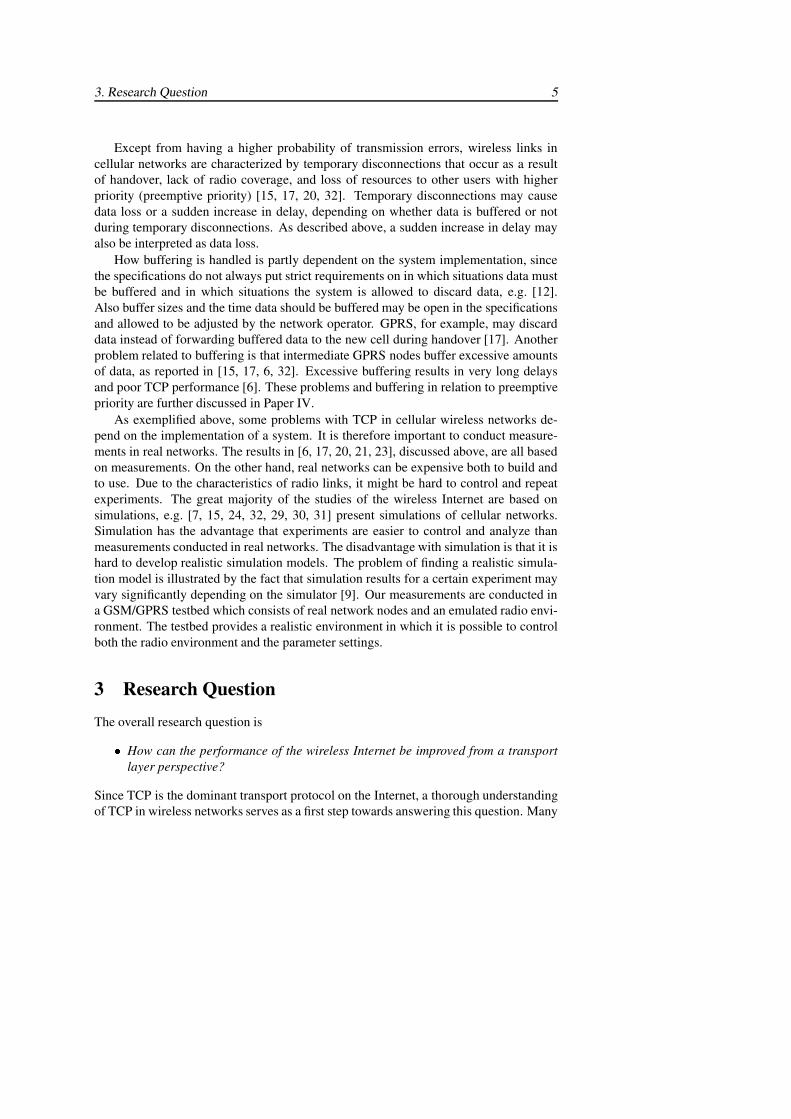
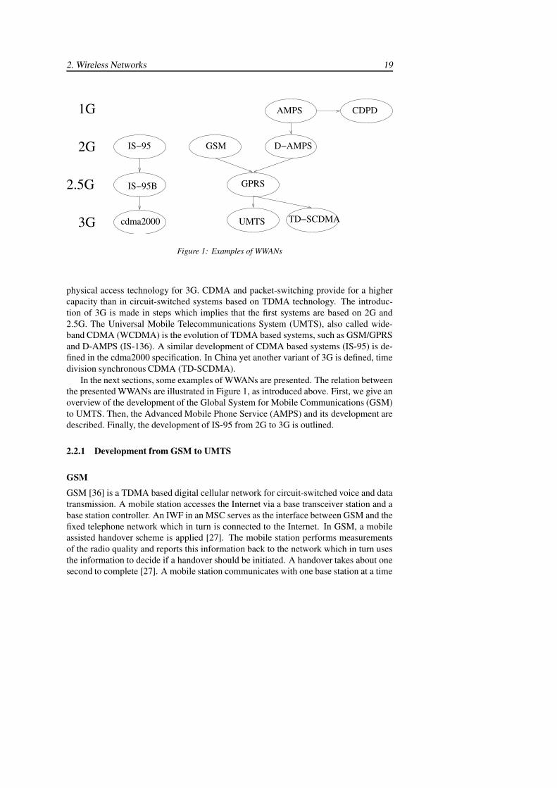
physical access technology for 3G. CDMA and packet-switching provide for a highercapacity than in circuit-switched systems based on TDMA technology. The introduc-tion of 3G is made in steps which implies that the first systems are based on 2G and2.5G. The Universal Mobile Telecommunications System (UMTS), also called wide-band CDMA (WCDMA) is the evolution of TDMA based systems, such as GSM/GPRSand D-AMPS (IS-136). A similar development of CDMA based systems (IS-95) is de-fined in the cdma2000 specification. In China yet another variant of 3G is defined, timedivision synchronous CDMA (TD-SCDMA).
In the next sections, some examples of WWANs are presented. The relation betweenthe presented WWANs are illustrated in Figure 1, as introduced above. First, we give anoverview of the development of the Global System for Mobile Communications (GSM)to UMTS. Then, the Advanced Mobile Phone Service (AMPS) and its development aredescribed. Finally, the development of IS-95 from 2G to 3G is outlined.
2.2.1 Development from GSM to UMTS
GSM
GSM [36] is a TDMA based digital cellular network for circuit-switched voice and datatransmission. A mobile station accesses the Internet via a base transceiver station and abase station controller. An IWF in an MSC serves as the interface between GSM and thefixed telephone network which in turn is connected to the Internet. In GSM, a mobileassisted handover scheme is applied [27]. The mobile station performs measurementsof the radio quality and reports this information back to the network which in turn usesthe information to decide if a handover should be initiated. A handover takes about onesecond to complete [27]. A mobile station communicates with one base station at a time
20 TCP over Wireless Networks
which implies that a short interruption occurs due to handover.
The data service available in GSM provides transparent and non-transparent modesof operation. The non-transparent mode uses an radio link protocol (RLP) [15] betweenthe mobile station and the IWF. The retransmission scheme is a selective repeat ARQbased on positive acknowledgments. The frames size is 240 bits in single-link modeand 576 bits in multi-link mode. Frames are retransmitted in response to a reject, aselective reject or a status report request that the sender requests from the receiver if noacknowledgment has arrived after timeout interval.
Depending on the RLP implementation, the link is either reset or disconnected aftera limited number of repeated retransmissions of the same frame. The maximum numberof retransmissions is configurable with a default value of 6. An implementation thatresets the link provides a partially or highly reliable service, depending on the maximumnumber or retransmissions [17]. At link reset, the RLP entities empty their buffers andfurther error recovery of lost data is silently left to higher layers. A fully reliable RLP,on the other hand, disconnects the link and notifies its users [28]. Data is not, as in thereset case, silently discarded by the link layer.
GPRS
General Packet Radio Service (GPRS) [16, 8, 41, 42] is a packet oriented extension toGSM which provides for higher data rates and more efficient network utilization com-pared to circuit-switched GSM. GSM channels, each corresponding to a time slot, mayeither be reserved for GPRS or dynamically allocated when required. If no channelsare exclusively reserved, a GPRS transfer may be interrupted due to preemption by traf-fic with higher priority, such as circuit-switched GSM. The data rate depends on thecoding scheme. A mobile station may receive data on up to eight GSM channels, butmost terminals today are not capable of receiving data on more than four channels. Themaximum data rate for the most commonly used coding scheme (CS-2) is 13.4kbps perchannel.
The new functions required for GPRS are provided by GPRS support nodes whichare connected by an IP-based GPRS backbone. Gateway GPRS support nodes (GGSNs)serve as interfaces between the GPRS network and other packet data networks such asthe Internet. Serving GPRS support nodes (SGSNs) are responsible for routing packetsto the right base station subsystem.
An LLC protocol between the mobile station and an SGSN provides acknowledgedand unacknowledged modes of operation. The maximum LLC frame size is 1556 bytes.A radio link control (RLC) protocol between the mobile station and the base station sys-tem fragments the LLC frames if necessary to fit into blocks suitable for transmissionover the radio interface. The RLC frame size is 256 bits for CS-2. RLC also supportsacknowledged and unacknowledged modes of operation. The MAC protocol used forchannel access is a slotted ALOHA reservation protocol.
2. Wireless Networks 21
UMTS
In UMTS [48], as compared to GPRS, functionality has moved from the core networkto the radio access network, the UMTS terrestrial radio access network (UTRAN). Theradio resource management, for example, is placed closer to the mobile station, in theradio network controller (RNC) instead of in the SGSN. No LLC protocol is thereforerequired between the MS and the SGSN. This gives a lower protocol overhead. The RLCprotocol in UMTS supports transparent, unacknowledged and acknowledged modes ofoperation. The transparent mode provides a byte stream service to the layer above. Theoverhead is lower than in other modes, since no RLC header is added. Error correctionis performed only in acknowledged mode. A sliding window based ARQ scheme usesselective repeat to request retransmission. The RLC block size is configurable withtypical values of around 320 bits. Retransmissions are triggered by acknowledgmentscalled status report messages that are transmitted by the receiver. The status reportmessages serve as both positive and negative acknowledgments, i.e. received framesare cumulatively acknowledged and missing blocks are indicated. The RLC receivertransmits a status report message in three cases: to request retransmission of erroneousRLC blocks, in response to poll messages from the sender, and at certain times as aperiodic event. Retransmissions have a higher priority than new data blocks. RLCdelivers data in order and removes duplicates before delivery. The reliability is low tohigh depending on the the maximum number of retransmissions, which can be set to avalue of up to 40.
2.2.2 Development from AMPS to D-AMPS and CDPD
The analog system used in North America, AMPS, has been developed into the digitaladvanced mobile phone service (D-AMPS), a digital 2G system, and into the cellulardigital packet data (CDPD) system, a packet data overlay network on top of the analogAMPS system.
D-AMPS
D-AMPS [44] is a TDMA based system, which is similar to GSM. As in GSM, a mobileassisted handover scheme is applied [27]. Also the RLP is similar to the one used inGSM. In contrast to GSM, a selective reject may be used to request retransmission ofmultiple frames. The size of an RLP frame is 256 bits, and each frame has a sequencenumber in the range 0-127 and a 16-bit checksum. The maximum data rate is 9.6 kbps.The 2.5G development of D-AMPS is also similar to GSM, since D-AMPS is extendedto provide GPRS.
CDPD
CDPD [44, 41] is an infrastructure for packet-switched data that is implemented as anoverlay network to the analog AMPS system. CDPD uses idle voice channels to transmitdata and if no channel is available packets will be delayed until a channel becomes free.
22 TCP over Wireless Networks
The data rate achieved after error coding is 9.6 kbps. As analog cellular networks arebeing replaced, the packet operations provided by CDPD will be taken over by secondand third generation cellular networks.
In AMPS, network controlled handover is applied [27]. This type of handover isless efficient than the mobile assisted handover used in GSM and D-AMPS. The basestations must measure the radio quality of the mobile stations and transmit this informa-tion to other base stations and to the MSC. Handover may take up to ten seconds, sinceextensive signaling is required and the radio quality is measured infrequently.
Digital carrier sense multiple access (DSMA/CD) is the medium access controlprotocol used in CDPD. The protocol is similar to the carrier sense multiple access(CSMA/CA) protocol used in wireless LANs described above. A mobile station thathas data to transmit must first check if a busy/idle flag bit is set on the forward channelbefore it can contend for the reverse channel. The mobile data link protocol (MDLP)manages logical links between a mobile end system and a mobile data intermediatesystem which is the node connecting the CDPD network with external packet orientednetworks. The protocol supports both acknowledged and unacknowledged mode of op-eration. Between the network and link layer lies the subnetwork dependent convergenceprotocol (SNDCP). SNDCP segments network protocol data units which have a maxi-mum size of 2048 bytes into blocks of 130 bytes (default value) that are passed to thelink layer.
2.2.3 Development from IS-95 to cdma2000
IS-95
IS-95 is a 2G digital cellular system [13, 24, 25] based on CDMA. IS-95 and its laterrevision, IS-95B, are also called cdmaOne. The network architecture is similar to GSMand D-AMPS. A mobile station is connected to a base station and a base station con-troller, and an MSC interconnects the wireless network with external networks. Thehandover scheme is also similar to GSM and D-AMPS in that the mobile assists the net-work with measurements of the radio quality. In contrast to the TDMA systems, IS-95CDMA supports soft handover [27], as described above.
For data transmission in IS-95 [25], a non-transparent mode of operation uses anRLP based on negative acknowledgments (NAKs). The retransmission scheme is lesscomplex than the one used in GSM. The receiver requests a retransmission by sendingNAKs to the sender. The NAK scheme is possible, since the system is synchronous andRLP frames are transmitted every 20ms. When there is no data to transmit, the sendertransmits the sequence number of the last data frame in an idle frame (which requires lessresources than a data frame). The receiver responds with NAKs if frames are missing. Ifa (1,2,3) NAK scheme is used (other schemes are possible), the receiver first transmitsone NAK after a timeout period. If data is still missing after a second timeout period,then two NAKs are transmitted. Finally, after a third timeout period, three NAKs are
2. Wireless Networks 23
transmitted. After the attempt with three NAK rounds for the same frame, RLP gives upand leaves further error recovery to higher layers.
The maximum data rate is 9.6kbps. The frame size is 171 or 266 bits, dependingon the rate. Undetected errors may occur, since the frame checksum is relatively weak,only 8 or 12 bits per frame depending on the rate [25].
IS-95B
IS-95B is the 2.5G development of IS-95. Packet-switched data services are added tothe IS-95 system by a software upgrade in the base stations and new user terminals. Asin GPRS, up to eight channels may be assigned to one user which gives a maximum datarate of 115kbps. In practice, the achievable data rate is about 64kbps.
cdma2000
The cdma2000 specification is a 3G development of IS-95. In contrast to UMTS, it ispossible to reuse the radio spectrum, bandwidth, and radio interface from preceding 2Gand 2.5G, since these are already based on CDMA. The first step is cdma2000 1x whichgives a higher capacity for both voice and data as compared to previous systems. Theaverage throughput per user is 144kbps with instantaneous data rates of up to 307kbps.Even higher rates, up to 2-3Mbps, will be available with cdma2000 1xEV-DO (evolutionfor data only) and cdma2000 1xEV-DV (evolution for data and voice). The radio linkprotocol used over the air uses a selective repeat ARQ based on NAKs similar to the oneapplied in IS-95, described above. RLP performs a limited number of retransmissionsbefore it gives up. Error detection and further error recovery are left to upper layers.
2.3 Conclusion
In comparison to fixed networks, wireless networks may seem to all have very similarproperties. However, as presented above, a closer investigation shows that there are someimportant difference between various systems. Next, the presented wireless networksare summarized and contrasted with emphasize on characteristics that may affect upperprotocol layers.
When the radio quality is low, data loss may occur over a wireless link due to trans-mission errors. The link level ARQ is capable of providing reliability is most cases,especially if the ARQ is highly persistent as in many cellular networks. In WLANs, onthe other hand, data may be lost if the radio conditions are very poor, since only a fewretransmission attempts are made. In cellular networks, handover is a more likely causeto data loss [21]. Data loss due to handover occurs particularly often if a user moves athigh speed.
Handover typically results in delay and, in many cases, also in data loss. Delay isintroduced, since it takes time to forward data to the new base station and to performthe handover procedure, e.g. signaling messages must be transmitted between the nodesinvolved in the handover. Data loss occurs if the old base station flushes its buffer instead
24 TCP over Wireless Networks
of forwarding data to the new base station. Data loss due to handover can be avoided ifa logical link protocol that performs ARQ is used on an additional link layer above theradio link protocol. Some examples are LLC in acknowledged mode in GPRS, and thelogical link protocol used in CDPD. Even so, the handover is not transparent to upperlayers, since recovery of lost data introduces delay.
Wireless networks have a long delay compared to wired networks, since transmissionover a radio interface is slower than over a wired medium. Additional delay may beintroduced due to processing on the physical layer and on the data link layer. Processingon the physical layer results in a constant delay. In cellular networks, processing onthe physical layer (error correction and interleaving) is extensive and therefore gives arelatively long delay. On the data link layer, delay is increased by the use of MAC andARQ. This delay is variable, since it depends on other users’ activity (MAC) and onthe radio conditions (ARQ). The delay variation experienced by upper protocol layersmay become very large if the link layer ARQ is highly persistent as in GSM, GPRS andUMTS (depending on the configuration).
3 TCPTCP [39] is a connection oriented transport protocol which provides a reliable bytestream to the application layer. Application data submitted to TCP is divided into pro-tocol data units (PDUs) called segments, before transmission. Reliability is achievedsince TCP uses an ARQ mechanism based on positive acknowledgments. Each byte isnumbered and the number of the first byte in a segment is used as a sequence number inthe TCP header. A receiver transmits a cumulative acknowledgment in response to anincoming segment which implies that many segments can be acknowledged at the sametime.
TCP manages a retransmission timer which is started when a segment is transmit-ted. If the timer expires before the segment is acknowledged, then TCP retransmits thesegment. The retransmission timeout value (RTO) is calculated dynamically based onmeasurements of the round trip time (RTT) [38], i.e. the time it takes from the transmis-sion of a segment until the acknowledgment is received.
In October 1986 the Internet had its first congestion collapse. The end hosts trans-mitted more data than the routers were able to handle, and did not lower the transmis-sion rate even though many packets were lost. Hence the congested state persisted inthe routers. Since then TCP has been extended with mechanisms for congestion con-trol [23]. Today all TCP implementations are required to use algorithms for congestioncontrol, namely, slow start, congestion avoidance, fast retransmit, and fast recovery [3].
3.1 Slow Start and Congestion AvoidanceThe purpose of slow start and congestion avoidance is to control the transmission rate inorder to prevent congestion from occurring. TCP is described as a self-clocking proto-
3. TCP 25
cwnd(segments)
round−trip times
0
2
4
6
10
12
14
16
18
ssthresh
20
8
8 9 13121110 141 2 3 4 5 6 70
ssthresh
timeout
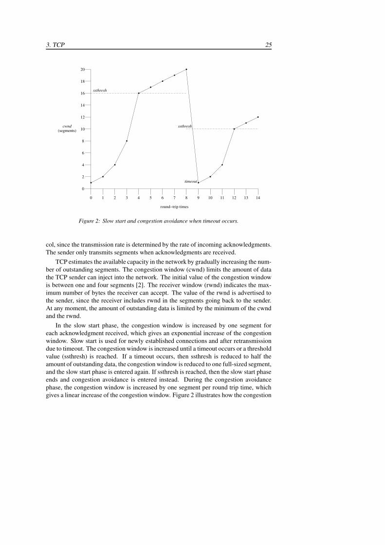
Figure 2: Slow start and congestion avoidance when timeout occurs.
col, since the transmission rate is determined by the rate of incoming acknowledgments.The sender only transmits segments when acknowledgments are received.
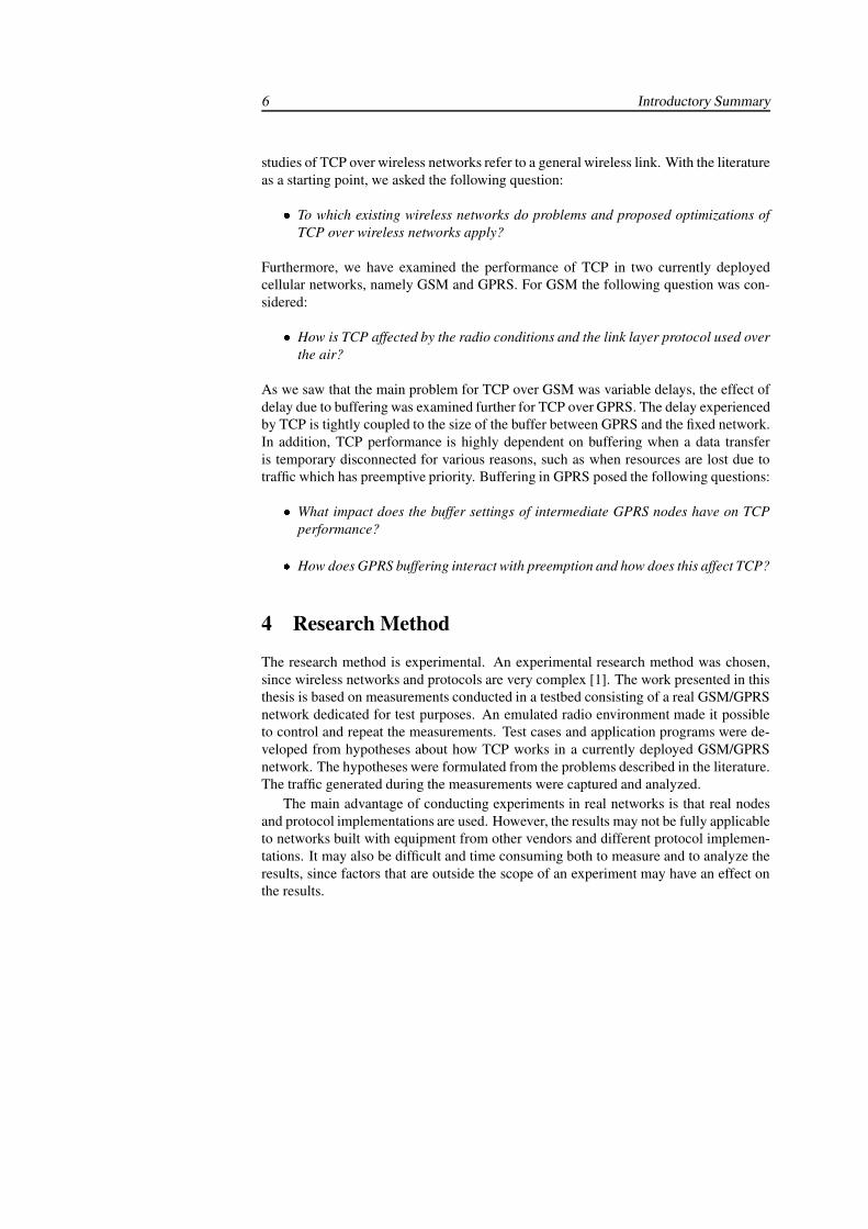
TCP estimates the available capacity in the network by gradually increasing the num-ber of outstanding segments. The congestion window (cwnd) limits the amount of datathe TCP sender can inject into the network. The initial value of the congestion windowis between one and four segments [2]. The receiver window (rwnd) indicates the max-imum number of bytes the receiver can accept. The value of the rwnd is advertised tothe sender, since the receiver includes rwnd in the segments going back to the sender.At any moment, the amount of outstanding data is limited by the minimum of the cwndand the rwnd.
In the slow start phase, the congestion window is increased by one segment foreach acknowledgment received, which gives an exponential increase of the congestionwindow. Slow start is used for newly established connections and after retransmissiondue to timeout. The congestion window is increased until a timeout occurs or a thresholdvalue (ssthresh) is reached. If a timeout occurs, then ssthresh is reduced to half theamount of outstanding data, the congestion window is reduced to one full-sized segment,and the slow start phase is entered again. If ssthresh is reached, then the slow start phaseends and congestion avoidance is entered instead. During the congestion avoidancephase, the congestion window is increased by one segment per round trip time, whichgives a linear increase of the congestion window. Figure 2 illustrates how the congestion
26 TCP over Wireless Networks
window is changed in slow start and in congestion avoidance.As compared to the congestion collapse discussed above, these algorithms make
TCP slow down when packets are lost. With less packets injected into the network, theload on the routers decreases and packets can flow through.
3.2 Fast Retransmit and Fast RecoveryThe fast retransmit and fast recovery algorithms [3] allow TCP to detect data loss andperform error recovery before the transmission timer expires in some situations. Thealgorithms increase TCP performance, partly due to the earlier loss detection and re-transmission, partly since the transmission rate is not reduced as much as after timeout.
If a segment arrives out of order, the receiver transmits an acknowledgment for thelast segment received in sequence. Since this segment already has been acknowledgedonce before, when it was first received, this subsequent acknowledgment is called a du-plicate acknowledgment (dupack). After receiving three dupacks in a row, the senderconcludes that unacknowledged data that was transmitted before the dupacked segmentmust have been lost. Data is retransmitted directly after the receipt of the third du-pack (the fourth acknowledgment) even if the retransmission timer has not expired. Thessthresh is reduced, as after timeout, to half the amount of outstanding data. After the re-transmission, fast recovery is performed until all lost data is recovered. The congestionwindow is set a higher value than after timeout, to three full-sized segments more thanssthresh. The additional three segments accounts for the three segments which triggeredthe receiver to transmit the dupacks. If more dupacks are received, then the congestionwindow is increased with one segment for each dupack, since each dupack indicates thatone segment has left the network. The fast recovery phase ends when an acknowledg-ment which covers new data is received. The congestion window is then set to the samevalue as ssthresh. The effect of this adjustment of the congestion window after fast re-transmit and fast recovery, is that TCP may enter congestion avoidance instead of slowstart, as is done after timeout.
3.3 TCP OptionsThe performance of TCP may be enhanced by the use of optional features. Some of thecommonly used options which are relevant for TCP in wireless networks are selectiveacknowledgments (SACK) [32], timestamps [22] and window scaling [22].
3.3.1 Selective Acknowledgments
The selective acknowledgment options (SACKs) [32] improves TCP performance, ifmultiple segments are lost in the same window. With SACK enabled, a receiver canacknowledge up to three non-continuous blocks of received bytes in the same acknowl-edgment. The sender then knows which segments are missing and can retransmit onlythose.
3. TCP 27
3.3.2 Timestamps
The timestamps option [22] provides an additional means to identify segments and theiracknowledgments. A 12 byte timestamp is added to outgoing segments and the receiveradds the same timestamp to the acknowledgments going back to the sender. If the times-tamps option is enabled, then the sender can sample the round trip time with a higherfrequency, which gives a more accurate round trip time estimation. This is especiallyuseful when large windows are used, since the round trip time can be estimated moreoften than only once per window.
3.3.3 Window Scaling
The window scale option [22] can be used in order to utilize the network capacity be-tween the sender and the receiver more efficiently. The bandwidth-delay product (ameasure of the capacity) may be larger than the maximum value of the header field forthe advertised receiver window (16 bits). This means that the transmission is limited bythe advertised receiver window, although the network can transport more data. With thewindow scale option, a larger window can be used, since, it is possible to advertise areceiver window of 32 bits.
3.4 Other Mechanisms3.4.1 Limited Transmit
Limited transmit [1] is a modification to the loss recovery algorithm in TCP. Withoutlimited transmit, TCP segments are only retransmitted at timeout or when three du-packs are received, as discussed earlier. The limited transmit mechanism allows TCP totransmit a new segment already when the first dupack arrives. The arrival of a dupackindicates that one segment has reached the receiver and left the network. By transmit-ting a new segment, TCP checks if the network is congested or not. If the new segmentreaches the receiver, the probability of fast retransmit is increased, since the receivertransmits a dupack in response to the new segment.
Limited transmit improves TCP performance when the transmission window is toosmall for fast retransmit and fast recovery to be triggered. For example, if the window isonly two packets, the sender may only transmit two packets and therefore three dupackscan not be generated. Limited transmit allows for injection of more packets which maylead to more dupacks, which then trigger fast retransmit.
3.4.2 Increased Initial Window
In [2], it is proposed to allow an initial value of the congestion window of up to foursegments, instead of up to two segments [3]. A larger initial value of the congestion win-dow increases TCP performance, especially for connections over which a small amountof data is transmitted. Fewer round trip times are required before the congestion window
28 TCP over Wireless Networks
opens up and the total transmission time for a certain amount of data is shorter than itwould be with a smaller initial window.
3.5 TCP VariantsThere are many implementations of TCP, some of which are considered as baseline TCPimplementations. Three TCP implementations in the BSD operating system, namedTahoe, Reno and NewReno, are the ones most commonly referred to. TCP Tahoe isthe original 4.4BSD implementation, including the congestion control scheme devisedby Jacobson [23], i.e. the slow start and congestion avoidance algorithms mentionedearlier. The addition of the fast retransmit and fast recovery algorithms [3] to TCPTahoe are called TCP Reno. TCP NewReno [18] further improves upon TCP Reno bychanging some thresholds in the fast recovery algorithm and avoiding a scenario wheremultiple retransmits can occur after timeout.
However, as TCP additions and modifications are continuously proposed and im-plemented, TCP implementations are not that easily classified to these three originalimplementations. For example, the Linux TCP includes most standardized features,such as selective acknowledgments, timestamps, and window scaling, as well as moreexperimental features [43].
4 Problems with TCP in Wireless NetworksThe performance of TCP is generally lower in wireless networks than in fixed. Thisis explained by the fact that TCP cannot distinguish problems that typically occur inwireless networks from congestion. The congestion control algorithms in TCP are basedon the assumptions that data is lost mainly due to congestion and that data loss dueto transmission errors is rare [23]. Therefore, data loss is interpreted as a signal ofcongestion in the network. Even in a wireless network, where data loss may not berelated to congestion, data loss still signals congestion to the sender.
TCP segments may be lost if the radio conditions are poor and the link layer protocolprovides a low reliability. After some retransmission attempts the link layer protocolgives up and leaves further error recovery to TCP. Handover events may also lead todata loss. A whole window of data may be lost due to handover. Data loss due toan unreliable link layer or a handover, may cause a timeout event followed by slowstart or three dupacks followed by fast retransmit and fast recovery. In either case, thecongestion control action taken by TCP is unnecessary. Directly after the loss event,the radio quality may become high again, and after handover data may be transmittedwithout problems to the new base station.
TCP may also misinterpret a sudden increase in the round trip time as data loss. Ifthe delay is long enough for the retransmission timer to expire before an acknowledg-ment is received, then TCP misinterprets the delay as an indication of data loss due tocongestion. The delayed data is unnecessarily retransmitted and TCP enters slow start.
5. Proposed Optimizations 29
A highly variable round trip time can also lead to a large RTO, since the RTO is basedboth on estimates of the round trip time and on variations in the round trip time. Ifthe RTO is large, then TCP reacts slowly to data loss. Variations in the round trip timecan be caused by link level retransmissions of a wireless link. If the link layer framesthat contain a TCP segment must be retransmitted because of a poor radio environment,then the whole segment is delayed. Round trip time variations may also be caused byhandover or competing traffic. Queuing in routers, base stations, and other intermediatenodes may also lead to a long round trip time. A long round trip time may cause lowthroughput and underutilization of the network, since it takes a number of round triptimes before the congestion window reaches the capacity of the network. TCP perfor-mance is degraded, especially for short lived flows, which transmits a small amount ofdata.
5 Proposed OptimizationsThis section gives an overview of some optimizations that have been proposed to im-prove TCP performance over wireless networks. The proposed optimizations are catego-rized into four groups: link layer, split connection, explicit notification, and end-to-end.Link layer optimizations for improved TCP performance are presented in Section 5.1.Section 5.2 describe how optimization at the transport layer can be achieved by splittingconnections in an intermediate node between the wireless and the fixed network. In or-der to distinguish congestion related losses from losses in the wireless network explicitnotifications can be used between an intermediate node and the end hosts. Examples ofexplicit notification approaches are given in Section 5.3. In Section 5.4, some end-to-end approaches are described. End-to-end approaches do not require any modificationsof intermediate nodes, only of the end hosts.
5.1 Link LayerThe idea behind the proposals presented in this section is to improve TCP performance atthe link layer. By using link level retransmissions locally over the wireless link, insteadof end-to-end retransmissions, the probability of packet loss due to problems over thewireless part of the connection is decreased. The purpose of the proposals is to increaseTCP performance over wireless links that provide low or no reliability.
5.1.1 Snoop
One of the first approaches to improve TCP performance over wireless links, Snoop, ispresented in [7]. The Snoop scheme uses link layer retransmissions to improve the relia-bility of the wireless link and at the same time it actively tries to avoid unnecessary TCPretransmissions. Snoop is implemented as an agent in the base station. Snoop cacheslink layer frames and examines the contents of TCP headers, but it does not require TCP
30 TCP over Wireless Networks
to run in the base station. A retransmission over the wireless link is triggered at the basestation after a link layer timeout period or if a duplicate acknowledgment arrives fromthe mobile station, which is assumed to be the receiver. When the first duplicate ac-knowledgment arrives the base station retransmits the lost, or possibly out-of-sequence,frame. Further duplicate acknowledgments from the mobile station are dropped at thebase station. This prevents the sender in the fixed network from performing fast retrans-mit and fast recovery while link layer retransmissions are performed over the wirelesslink.
5.1.2 WTCP (Ratnam and Matta)
WTCP [40] is similar to Snoop in that the base station performs retransmissions overthe wireless link based on timeouts and duplicate acknowledgments. In addition, WTCPfurther improves TCP performance by using the timestamps option [22] and by limitingthe amount of outstanding data over the wireless link. WTCP operates in the base sta-tion and the only modification required at the end hosts is that the timestamps option isenabled. The base station increments the timestamp in the TCP header for each retrans-mission that is required over the wireless link. This gives a more accurate RTT estimate.For acknowledgments from the mobile station, on the other hand, the base station leavesthe timestamp unchanged. Furthermore, WTCP changes the limit on outstanding datathat it allows over the wireless link. If a timeout occurs, then the wireless link is as-sumed to be in a bad state. After timeout, only one segment is allowed to be outstandingover the wireless link. When acknowledgments come back to the base station again, thewireless link is assumed to be in a good state and the limit on outstanding data is set tothe same value as the receiver window.
5.1.3 TULIP
In [37], the transport unaware link improvement protocol (TULIP) is proposed to im-prove TCP performance over half-duplex radio links, e.g. IEEE 802.11. TULIP is de-scribed as transport unaware, since it does not use information in the TCP header, butrelies only on the protocol field in the IP header. TULIP provides a reliable servicefor TCP data segments, and an unreliable service for UDP and TCP acknowledgments.TULIP provides in-order delivery of packets, which prevents unnecessary fast retrans-mits.
5.1.4 Conclusion
The proposals presented above use link level retransmissions to minimize packet lossdue to the wireless part of a connection. The link level proposals are intended for wire-less links with very low persistent ARQ protocols. All the proposals preserve the end-to-end semantics of TCP, but TCP data and acknowledgments are required to pass through
5. Proposed Optimizations 31
the same base station (or other intermediate node in which the optimization is imple-mented). In the TCP-aware approaches, Snoop and WTCP, the base station is requiredto process information in the TCP header, which is based on the assumption that eachTCP segment is encapsulated in a link layer frame. This is usually the case in WLANs,but not in most other wireless networks. If the link layer frame used over the radio inter-face is to small to encapsulate a TCP segment, as in many WWANs, then the link layerproposals could operate on the logical link control layer instead (provided that a TCPsegment fits into a frame). Unfortunately, if TCP headers are encrypted due to securityon the IP layer (IPsec) [26], the TCP-aware approach will not work.
5.2 Split Connection
The idea of split connection approaches is to divide each TCP connection into two sep-arate connections at an intermediate node. By splitting connections congestion relatedlosses in the wired network are discriminated from wireless losses. Many split connec-tion proposals use TCP, or modified versions of TCP, also over the wireless link. Anytransport protocol that is suitable for wireless communication may be used over the wire-less link. Another protocol stack may also be used over the wireless link, for exampleas is done in WAP 1.0 [50].
5.2.1 Indirect TCP
Indirect TCP (I-TCP) [4] is intended primarily for WLANs with support for mobility atthe IP level. An I-TCP connection between a mobile station and a fixed host is split at thebase station into one connection over the wireless network and one over the fixed. Whenthe mobile station moves and a handover occurs, TCP state is transferred to the newbase station and the retransmission timer is reset. A consequence of this is that the fixedhost will be less affected by delay caused by handover and link level retransmissions.Even though TCP is used also over the wireless link, the performance is improved ascompared to having one connection all the way. This is explained by the fact that theround trip time becomes shorter. Therefore, the TCP sender in the base station canrecover faster from data loss, especially if the connection over the fixed part experiencesa non-negligible delay, but the wireless link still is the bottleneck.
5.2.2 MTCP and Selective Repeat Protocol
Two alternative split connection schemes are described in [51]. Both support mobilityon top of a version of mobile IP. After a handover the TCP states of the connections aretransmitted to the new base station. The first alternative, MTCP, uses standard TCP alsoover the wireless network. For the second alternative a selective repeat protocol (SRP)suitable for wireless communication is used instead of TCP between the base station andthe mobile station. SRP is a UDP based protocol that performs flow and error control
32 TCP over Wireless Networks
optimized for wireless links. Since SRP uses selective acknowledgments, it is possibleto recover more than one segment each round trip time.
5.2.3 Conclusion
By splitting a TCP connection, data loss due to handover can be avoided if data andstate information are forwarded to the new base station. Furthermore, with the split, it ispossible to discriminate data loss over the wireless link from data loss that occurs overthe fixed network. The proposals have similar disadvantages as the link layer proposalspresented above. All data to and from the mobile station is required to pass the samebase station (or some other intermediate node which splits the connection). TCP headersmust be processed, which implies that the split connection schemes do not work withIPsec. In addition, the end-to-end semantics of TCP are not preserved. The presentedproposals are intended for WLANs which support mobility on the IP level. However,split connection proposals may improve TCP performance also in other environments,since a shorter round trip time results is faster error recovery. An example of this isprovided in [34], which evaluates a split connection proxy in WCDMA.
5.3 Explicit Notification
As TCP interprets all losses as congestion in the network, various explicit notificationschemes have been proposed to enable the TCP sender to identify the real cause of adata loss. The idea is that an explicit notification is transmitted in order to inform thesender about data loss due to corruption in the wireless network.
5.3.1 ICMP Messaging
Instead of trying to hide problems due to a wireless link, [19] proposes that an ex-plicit notification is transmitted to the TCP sender. The idea is that the intermediatenode that connects the fixed and the wireless network has information about the wirelesstransmission success, and should be responsible for generating and transmitting explicitnotifications. A new ICMP message type, ICMP-DEFER, is used for the explicit no-tification. If data is lost over the wireless network, an ICMP-DEFER is transmittedto the TCP sender, which postpones the expiration of the retransmission timer. Thisavoids conflicts between the link level retransmissions at the base station and end-to-end retransmissions. If a segment needs retransmission and an ICMP-DEFER has beenreceived, then the cwnd is not reduced at the sender. The scheme is further improvedby adding another ICMP message, ICMP-RETRANSMISSION. The base station trans-mits an ICMP-RETRANSMISSION to the TCP sender when the maximum number ofretransmission attempts is reached and the packet is discarded.
5. Proposed Optimizations 33
5.3.2 Explicit Loss Notification
Explicit Loss Notification (ELN) [5] can be used if the mobile host is the sender. If datais lost over the wireless link, the base station transmits an ELN to the mobile station(the sender). The base station examines TCP headers and keeps track of the sequencenumbers. A hole in the sequence space indicates that data must have been lost overthe wireless link on its way from the mobile station to the base station. The fixed host(the receiver) transmits a dupack in response. The base station sets an ELN flag in thedupack header before the dupack is forwarded to the mobile station. The mobile stationthen retransmits the lost segment but does not reduce its congestion window.
5.3.3 Syndrome
Syndrome [12] is a modification of the base station to enable detection of packet lossover the wireless link. The base station counts the number of packets it relays, andincludes this counter as a TCP option. This counter is called a ”syndrome”, and isused together with the sequence number to determine if a loss occurred in the wired orwireless part of the network. If there is a gap in the syndrome counter, this indicatesthat packets were lost on the wireless part. Gaps in sequence numbers, but not in thesyndrome, indicate that segments must have been lost in the fixed network. Explicit lossnotification is then used by the receiver to inform the sender about the loss.
5.3.4 Partial Acknowledgments
Another means to distinguish congestion from data loss due to a wireless link is tointroduce new types of acknowledgments. The proposal described in [9] uses one ad-ditional acknowledgment, a partial acknowledgment that the base station transmits inresponse to data from a sender in the fixed network. Provided that no segments are lost,the sender receives two acknowledgments for each segment: a partial acknowledgmentfrom the base station and a complete acknowledgment from the mobile host. If onlythe partial acknowledgment arrives, then the sender can conclude that data must havebeen lost over the wireless network and no congestion control action is required. If noacknowledgments arrive, then the most likely cause is data loss due to congestion.
A similar scheme, which introduces two new partial acknowledgments, is proposedin [14]. If the mobile station is the receiver, then the base station transmits a last hopacknowledgment in response to the fixed host. The scheme work also if the mobilestation is the sender. In that case the base station transmits a first hop acknowledgmentto the mobile station. As in the partial acknowledgment approach above, the senderreceives two acknowledgments for each successfully transmitted segment, one from thereceiver and one from the base station.
34 TCP over Wireless Networks
5.3.5 Conclusion
The explicit notification proposals have a different philosophy compared to most of theother proposals. The sender can distinguish congestion from data loss over the wirelessnetwork, since it receives information about the transmission status. This does not solvethe problem with the higher unreliability of the wireless network, but the sender knowsabout it and is able to make a more informed decision. One disadvantage of the explicitnotification schemes presented above is that they assume that the base station is TCP-aware. The only exception is ICMP messaging. Explicit notification assumes a lowpersistent link ARQ, such as in WLANs.
5.4 End-to-endOptimizations may also be placed entirely in the end-points to avoid adding complexityto the network. The proposals in this section differ from each other, but the underlyingidea that they have in common is to avoid congestion control action at the sender whendata is lost for some other reason than congestion.
5.4.1 TCP Westwood
TCP Westwood [11] is a sender-side modification that improves the congestion controlalgorithm in TCP Reno. Instead of relying on slowly probing the available bandwidthuntil segments are dropped, as in standard TCP, the rate of incoming acknowledgmentsis used to determine the available bandwidth. TCP Westwood has been shown to giveimprovements over wireless links as well as over wired. Error recovery is faster than instandard TCP, since the bandwidth estimation is considered when values for cwnd andssthresh are computed after data loss.
5.4.2 WTCP (Sinha et al.)
The Wireless Transmission Control Protocol (WTCP) [45] is aimed at improving theperformance in WWANs such as CDPD. As TCP Westwood, WTCP uses a rate basedapproach to control the transmission rate. Inter-packet separation at the sender and thereceiver is used as the primary metric for transmission rate calculations. This meansthat WTCP is more resilient to non-congestion related packet loss, thereby improvingperformance in wireless networks.
5.4.3 TCP Real
TCP Real [52] is a rate based scheme in which the receiver controls the transmission rateat sender. The receiver uses changes in the rate of incoming segments to compute thecongestion window the sender should use. If the rate of incoming segments is decreas-ing, then this is taken as an indication of an increasing load in the network and therefore
5. Proposed Optimizations 35
the cwnd should be decreased accordingly. After data loss, the cwnd is adjusted to thenetwork conditions sooner than in standard TCP, since the receiver includes estimates ofthe cwnd in the acknowledgments that go back to the sender.
5.4.4 Freeze-TCP
Freeze-TCP [20] is a mechanism to improve the performance of TCP in wireless en-vironments in which handover frequently occurs. By exploiting the properties of theadvertised receiver window, a TCP connection can be frozen. If the receiver sets the re-ceiver window to zero, then the sender leaves its cwnd unchanged until the receiver ad-vertises a new receiver window. Just before handover occurs, the mobile station freezesthe TCP connection by advertising a receiver window of zero. This prevents segmentsfrom getting lost and unnecessary congestion control action to be taken by the sender.When the handover is completed, the receiver sends an acknowledgment which opensup the window again. The transmission then continues at the same rate as before.
5.4.5 Delayed Dupack
The delayed dupack scheme proposed in [49] is an end-to-end scheme that imitatesSnoop. The third and subsequent dupacks are delayed while the base station performslink level retransmissions. This prevents the sender (fixed host) from taking congestioncontrol action while the base station retransmits data over the wireless link. The thirdand subsequent dupacks are delayed for a predetermined time interval. During this timethe receiver may receive the missing data and transmit a cumulative acknowledgmentinstead. The delayed dupacks are then discarded. If the missing segment is not received,then the delayed dupacks are instead released when the timer expires.
A disadvantage with the delayed dupacks scheme is that the dupacks are delayedalso in case of congestion, and hence error recovery is delayed. Explicit loss notificationto the receiver (ELNR) [33] is proposed as an enhancement to the delayed dupacksscheme. The mobile host delays dupacks unless it receives an ELNR which indicatesthat the network may be congested. The base station transmits an ELNR to the mobilehost if it receives a packet out-of-sequence. Upon receipt of an ELNR the mobile hostdoes not delay any dupacks. When the base station has received the missing packets,the base station transmits an explicit delayed dupack activation notification (EDDAN)to the mobile host. The EDDAN indicates that the network is no longer congested, andsubsequent dupacks should be delayed until a new ELNR arrives.
5.4.6 Eifel
The Eifel algorithm described in [30, 31, 29] allows the sender to detect whether an al-ready initiated error recovery action is necessary or not. When the first acknowledgmentthat covers previously unacknowledged data arrives, the sender can determine if this isan acknowledgment of the original segment or of a retransmission. The algorithm uses
36 TCP over Wireless Networks
the timestamps option to match acknowledgments with segments. If the first acknowl-edgment is for the original segment, then the retransmission is spurious and there is noreason for the sender to reduce the transmission rate. The original packet is not lost dueto congestion, but it has only been delayed before it arrived at the receiver.
5.4.7 Conclusion
The end-to-end proposals are based on various ideas. The rate based proposals try bothto avoid congestion and to recover quickly from random losses over the wireless net-work. Freeze-TCP prevents data loss by making a pause in the data transfer duringhandover. The Eifel algorithm, on the other hand, limits performance degradation oncedelay has already been misinterpreted as a sign of congestion. End-to-end proposals areadvantageous since the end-to-end semantics of TCP are preserved. The data transferredbetween the end hosts is not required to pass the same intermediate node. No additionalprocessing is required in the network and IPsec can be used.
5.5 Summary
The optimization proposals presented above, as illustrated by many different types ofapproaches, have been suggested to improve TCP performance over wireless networks.
The link layer approaches use link layer retransmissions to increase the reliabilityprovided to TCP. The requirements on the link layer service may vary depending on theapplication. This is, for example, considered in UMTS, since the radio link protocolallows configuration of many parameters, such as the maximum number of retransmis-sions.
There are many types of split connection proposals, only some of which are de-scribed in this report. Performance improvements are often significant, but at the costof violating the end-to-end semantics of TCP. The intermediate node which divides theconnection must process data up to the transport layer and all TCP segments belongingto the same connection are required to pass that node. The TCP-aware link layer pro-posals have similar limitations as the split connection proposals. However, the link layerproposals preserve the end-to-end semantics of TCP.
Most of the explicit notification proposals require TCP-awareness of the intermedi-ate node that is responsible for transmitting explicit notifications. These proposals seemto be intended for wireless links with low reliability. A link ARQ with higher persistencewould reduce or eliminate data loss due to an unreliable wireless link. However, anotherapplication of explicit notifications could be to signal to the TCP sender that a handoverhas been initiated.
End-to-end proposals are based on the idea that complexity belongs in the end hostsrather than in the network. The end-to-end semantics of TCP are preserved. Interme-diate nodes do not have to be TCP-aware, as in many of the other proposals. The datatransferred between the end hosts is not required to pass the same intermediate node.
REFERENCES 37
6 Concluding RemarksIn this report, some wireless networks that are used to access the Internet are described,the congestion control mechanisms in TCP are explained, and representative examplesof optimization proposals intended to increase TCP performance in wireless networksare provided. As TCP is one of the reasons for the success of the Internet, it is desirableto use TCP also in wireless networks. However, TCP performance is degraded morethan necessary due to non-congestion related packet loss and varying round trip times,incurred by the properties of wireless networks. Therefore, a number of optimizationshave been proposed to increase the performance of TCP over wireless networks. Theoptimization proposals are divided into link layer, split connection, explicit notificationand end-to-end optimizations. The optimization proposals all have the same goal, toimprove TCP performance over wireless networks, but different approaches are used toreach the goal. For example, some link layer optimizations try to emulate the behaviorof wired links by reducing the probability of non-congestion related loss, while opti-mizations that use explicit notifications aim for the opposite, that the end points shouldbe aware of the network heterogeneity. Some of the optimization proposals may im-prove TCP performance in many types of wireless networks, while others are intendedfor WLANs or for a specific WWAN.
In the future, wireless network technologies will provide a higher capacity. Even so,TCP performance will not automatically become optimal. Problems inherent to wirelessnetworks related to variable radio conditions and to handover will still be crucial to theperformance of TCP.
AcknowledgmentsThis work has been partly funded by the Swedish graduate school PCC++ and the re-search program CMIT. Figure 2 was created by Sean Schneyer.
References[1] M. Allman, H. Balakrishnan, and S. Floyd. RFC 3042: Enhancing TCP’s loss
recovery using limited transmit, January 2001.
[2] M. Allman, S. Floyd, and C. Partridge. RFC 3390: Increasing TCP’s initial win-dow, August 2002.
[3] M. Allman, V. Paxson, and W. Stevens. RFC 2581: TCP congestion control, April1999.
[4] A. V. Bakre and B. Badrinath. Implementation and performance evaluation ofIndirect TCP. IEEE Transactions on Computers, 46(3), March 1997.
38 TCP over Wireless Networks
[5] H. Balakrishnan and R. Katz. Explicit loss notification and wireless web perfor-mance. In Proceedings Globecom Internet Mini-Conference, Sydney, Australia,November 1998.
[6] H. Balakrishnan, V. N. Padmanabhan, S. Seshan, and R. H. Katz. A comparisonof mechanisms for improving TCP performance over wireless links. IEEE/ACMTransactions on Networking, 5(6):756–769, December 1997.
[7] H. Balakrishnan, S. Seshan, and R. H. Katz. Improving reliable transport andhandoff performance in cellular wireless networks. ACM Wireless Networks, 1(4),December 1995.
[8] C. Bettstetter, H.-J. Vogel, and J. Eberspacher. GSM phase 2+ general packet radioservice GPRS: Architecture, protocols, and air interface. IEEE CommunicationSurveys, 2(3), 1999.
[9] S. Biaz, M. Mehta, S. West, and N. H. Vaidya. TCP over wireless networks usingmultiple acknowledgements. Technical Report 97-001, Computer Science, TexasA&M University, January 1997.
[10] R. Caceres and L. Iftode. Improving the performance of reliable transport pro-tocols in mobile computing environments. IEEE Journal on Selected Areas inCommunications, 13, June 1995.
[11] C. Casetti, M. Gerla, S. Mascolo, M. Y. Sanadidi, and R. Wang. TCP Westwood:Bandwidth estimation for enhanced transport over wireless links. In Proceedingsof ACM Mobicom, pages 287–297, Rome, Italy, July 2001.
[12] W.-P. Chen, Y.-C. Hsiao, J. C. Hou, Y. Ge, and M. P. Fitz. Syndrome: a light-weightapproach to improving TCP performance in mobile wireless networks. WirelessCommunications and Mobile Computing, (2):37–57, 2002.
[13] M. C. Chuah, B. Doshi, S. Dravida, R. Ejzak, and S. Nanda. Link layer retrans-mission schemes for circuit-mode data over the CDMA physical channel. MobileNetworks and Applications, 2(2):195 – 211, October 1997.
[14] J. A. Cobb and P. Agrawal. Congestion or corruption? A strategy for efficientwireless TCP sessions. IEEE Symposium on Computers and Communications,Alexandria, Egypt, pages 262–268, 1995.
[15] ETSI. Digital cellular telecommunications system (Phase 2+); Radio Link Protocol(RLP) for data and telematic services on the Mobile Station - Base Station System(MS - BSS) interface and the Base Station System - Mobile-services SwitchingCentre (BSS - MSC) interface (GSM 04.22 version 7.0.1 Release 1998). ETSI,1999.
REFERENCES 39
[16] ETSI. Digital cellular telecommunications system (Phase 2+); General PacketRadio Service (GPRS); Service description; Stage 2 (GSM 03.60 version 6.7.0Release 1997), 2000.
[17] G. Fairhurst and L. Wood. RFC 3366: Advice to link designers on link AutomaticRepeat reQuest (ARQ), August 2002.
[18] S. Floyd. RFC 2582: The NewReno Modification to TCP’s Fast Recovery Algo-rithm, April 1999.
[19] S. Goel and D. Sanghi. Improving TCP performance over wireless links. Pro-ceedings of TENCON 98 - IEEE Region Ten Conference on Global Connectivity inEnergy, Computer Communication and Control, 1998.
[20] T. Goff, J. Moronski, D. Phatak, and V. V. Gupta. Freeze-TCP: A true end-to-end enhancement mechanism for mobile environments. In Proceedings of IEEEINFOCOM, March 2000.
[21] A. Gurtov and S. Floyd. Modeling wireless links for transport protocols. To appearin ACM Computer Communication Review, 2004.
[22] V. Jacobson, R. Braden, and D. Borman. RFC 1323: TCP extensions for highperformance, May 1992.
[23] V. Jacobson and M. J. Karels. Congestion avoidance and control. In Proceedingsof SIGCOMM ’88 Workshop, pages 314–329, 1988.
[24] P. Karn. The Qualcomm CDMA digital cellular system. In Proceedings of theUSENIX Mobile and Location-Independent Computing Symposium, pages 35–39,Aug. 1993.
[25] P. Karn. IP data services over CDMA digital cellular. Mobile Computing andCommunications Review, 4(4):30–35, October 2000.
[26] S. Kent and R. Atkinson. RFC 2401: Security architecture for the internet protocol,November 1998.
[27] Y.-B. Lin and I. Chlamtac. Wireless and Mobile Network Architectures. John Wiley& Sons, Inc., 2000.
[28] R. Ludwig. Eliminating inefficient cross-layer interactions in wireless networking.Ph.D. Thesis, Aachen University of Technology, Germany, April 2000.
[29] R. Ludwig and A. Gurtov. The Eifel response algorithm for TCP. Work in progress,IETF, 2003.
40 TCP over Wireless Networks
[30] R. Ludwig and R. H. Katz. The Eifel algorithm: Making TCP robust againstspurious retransmissions. ACM Computer Communication Review, 30(1):30–37,January 2000.
[31] R. Ludwig and M. Meyer. RFC 3522: The Eifel detection algorithm for TCP,2003.
[32] M. Mathis, J. Mahdavi, S. Floyd, and A. Romanow. RFC 2018: TCP selectiveacknowledgment options, October 1996.
[33] M. Mehta and N. H. Vaidya. Delayed duplicate acknowledgements: A proposalto improve performance of TCP on wireless links. Tecnical Report (Texas A&MUniversity), February 1998.
[34] M. Meyer, J. Sachs, and M. Holzke. Performance evaluation of a TCP proxyin WCDMA networks. IEEE Wireless Communications, 10(5):70 – 79, October2003.
[35] A. Mishra, M. Shin, and W. Arbaugh. An empirical analysis of the IEEE 802.11MAC layer handoff process. ACM Computer Communication Review, 33(2):93–102, 2003.
[36] M. Mouly and M.-B. Pautet. The GSM System for Mobile Communications. Cell& Sys, 1992.
[37] C. Parsa and J. Garcia-Luna-Aceves. Improving TCP performance over wirelessnetworks at the link layer. ACM Mobile Networks and Applications Journal, vol 5,issue 1., 2000.
[38] V. Paxson and M. Allman. RFC 2988: Computing TCP’s Retransmission Timer,November 2000.
[39] J. Postel. RFC 793: Transmission control protocol, September 1981.
[40] K. Ratnam and I. Matta. WTCP: An efficient transmission control protocol fornetworks with wireless links. In Proceedings of the third IEEE Symposium onComputers and Communications (ISCC ’98), Athens, Greece, June 1998.
[41] A. K. Salkintzis. A survey of mobile data networks. IEEE Communication Surveys,2(3), 1999.
[42] B. Sarikaya. Packet mode in wireless networks: Overview of transition to thirdgeneration. IEEE Communications Magazine, September 2000.
[43] P. Sarolahti and A. Kuznetsov. Congestion control in Linux TCP. In USENIX An-nual Technical Conference, FREENIX Track, pages 49–62, Monterey, California,USA, June 2002.
REFERENCES 41
[44] A. D. Simone and S. Nanda. Wireless data: systems, standards, service. WirelessNetworks, 1(3):241–253, March 1995.
[45] P. Sinha, T. Nandagopal, N. Venkitaraman, R. Sivakumar, and V. Bharghavan.WTCP: A reliable transport protocol for wireless wide-area networks. WirelessNetworks, 8(2):301–316, March 2002.
[46] W. Stallings. Mobile IP. The Internet Protocol Journal, 4(2):2–14, June 2001.
[47] W. Stallings. Wireless Communications and Networks. Prentice Hall, 2001.
[48] M. Taferner and E. Bonek. Wireless Internet Access over GSM and UMTS.Springer-Verlag, 2002.
[49] N. Vaidya, M. Mehta, C. Perkins, and G. Montenegro. Delayed duplicate acknowl-edgements: A TCP-unaware approach to improve performance of TCP over wire-less. Technical Report, Computer Science Dept., Texas A&M University, February1999.
[50] WAP Forum Ltd. Wireless Application Protocol - architecture specification.http://www.wapforum.org, page 20, April 1998.
[51] R. Yavatkar and N. Bhagwat. Improving end-to-end performance of TCP overmobile internetworks. Workshop on Mobile Computing Systems and Applications(Mobile 94), December 1994.
[52] C. Zhang and V. Tsaoussidis. TCP Real: Improving real-time capabilities of TCPover heterogeneous networks. Proceedings of the 11th IEEE/ACM NOSSDAV,2001.

Paper II
TCP and GSM Link Layer Interactions: Implicationsfor the Wireless Internet
Reprinted from
Proceedings of IEEE Semiannual Vehicular Technology Conference(VTC 2001 Spring)
Rhodes, Greece, May 2001.

TCP and GSM Link Layer Interactions:Implications for the Wireless Internet
Annika Wennstrom, Johan Garcia, Anna BrunstromDept. of Computer Science
Karlstad UniversitySE-651 88 Karlstad, Sweden�
Annika.Wennstrom, Johan.Garcia, Anna Brunstrom � @kau.se
Jan H. GustafssonTelia Mobile ABLagergrens gata 7
SE-651 15 Karlstad, [email protected]
Abstract
The demand for wireless access to the Internet has grown rapidly making theperformance of TCP in wireless environments an important issue. In this paperwe present experimental measurements of the performance of TCP over GSM. Themeasurements were captured over a real GSM network connected to a controlledradio environment. A range of radio conditions were considered with a focus onthe interaction between TCP and the GSM link layer. Even for very poor radioconditions, only neglible negative interaction effects were found.
1 IntroductionWith the growing importance of wireless Internet applications the performance of TCPover wireless networks has become a primary target for investigation. The performanceof applications such as wireless WWW browsing are of course strongly correlated tothe performance of TCP. It is well known that TCP performance over wireless networkscan suffer due to non-congestion induced losses and high variability in round trip times.Although many authors have considered general models of wireless networks, TCP per-formance is of course highly dependent on the particular wireless network consideredand on the design of the link layer protocol used for this network. Owing to the lead-ing market position of the GSM digital cellular network the performance of TCP in thisparticular environment is of high interest. In this paper we describe TCP performancemeasurements conducted over a real GSM network, but in a controlled radio environ-ment. The interaction of TCP and the GSM link layer was studied for a variety of radio
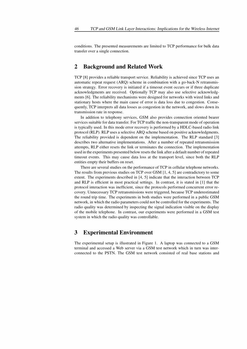
46 TCP and GSM Link Layer Interactions: Implications for the Wireless Internet
conditions. The presented measurements are limited to TCP performance for bulk datatransfer over a single connection.
2 Background and Related Work
TCP [8] provides a reliable transport service. Reliability is achieved since TCP uses anautomatic repeat request (ARQ) scheme in combination with a go-back-N retransmis-sion strategy. Error recovery is initiated if a timeout event occurs or if three duplicateacknowledgments are received. Optionally TCP may also use selective acknowledg-ments [6]. The reliability mechanisms were designed for networks with wired links andstationary hosts where the main cause of error is data loss due to congestion. Conse-quently, TCP interprets all data losses as congestion in the network, and slows down itstransmission rate in response.
In addition to telephony services, GSM also provides connection oriented bearerservices suitable for data transfer. For TCP traffic the non-transparent mode of operationis typically used. In this mode error recovery is performed by a HDLC-based radio linkprotocol (RLP). RLP uses a selective ARQ scheme based on positive acknowledgments.The reliability provided is dependent on the implementation. The RLP standard [3]describes two alternative implementations. After a number of repeated retransmissionattempts, RLP either resets the link or terminates the connection. The implementationused in the experiments presented below resets the link after a default number of repeatedtimeout events. This may cause data loss at the transport level, since both the RLPentities empty their buffers on reset.
There are several studies on the performance of TCP in cellular telephone networks.The results from previous studies on TCP over GSM [1, 4, 5] are contradictory to someextent. The experiments described in [4, 5] indicate that the interaction between TCPand RLP is efficient in most practical settings. In contrast, it is stated in [1] that theprotocol interaction was inefficient, since the protocols performed concurrent error re-covery. Unnecessary TCP retransmissions were triggered, because TCP underestimatedthe round trip time. The experiments in both studies were performed in a public GSMnetwork, in which the radio parameters could not be controlled for the experiments. Theradio quality was determined by inspecting the signal indication visible on the displayof the mobile telephone. In contrast, our experiments were performed in a GSM testsystem in which the radio quality was controllable.
3 Experimental Environment
The experimental setup is illustrated in Figure 1. A laptop was connected to a GSMterminal and accessed a Web server via a GSM test network which in turn was inter-connected to the PSTN. The GSM test network consisted of real base stations and
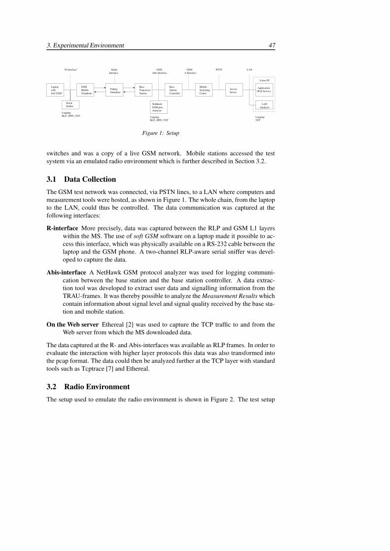
3. Experimental Environment 47
Linux PC
Logging:TCP
AccessServer
AnalyzerLAN
(Web Server)ApplicationLaptop
withSoft GSM
GSMMobileTelephone
Logging:RLP, (PPP), TCP
SerialSniffer
SimulatorFading
InterfaceRadio
BaseStationController
MobileSwitchingCenter
NetHawkGSM prot.Analyzer
Logging:RLP, (PPP), TCP
Abis InterfaceGSM
A InterfaceGSM
BaseTranceiverStation
"R Interface" PSTN LAN
Figure 1: Setup
switches and was a copy of a live GSM network. Mobile stations accessed the testsystem via an emulated radio environment which is further described in Section 3.2.
3.1 Data CollectionThe GSM test network was connected, via PSTN lines, to a LAN where computers andmeasurement tools were hosted, as shown in Figure 1. The whole chain, from the laptopto the LAN, could thus be controlled. The data communication was captured at thefollowing interfaces:
R-interface More precisely, data was captured between the RLP and GSM L1 layerswithin the MS. The use of soft GSM software on a laptop made it possible to ac-cess this interface, which was physically available on a RS-232 cable between thelaptop and the GSM phone. A two-channel RLP-aware serial sniffer was devel-oped to capture the data.
Abis-interface A NetHawk GSM protocol analyzer was used for logging communi-cation between the base station and the base station controller. A data extrac-tion tool was developed to extract user data and signalling information from theTRAU-frames. It was thereby possible to analyze the Measurement Results whichcontain information about signal level and signal quality received by the base sta-tion and mobile station.
On the Web server Ethereal [2] was used to capture the TCP traffic to and from theWeb server from which the MS downloaded data.
The data captured at the R- and Abis-interfaces was available as RLP frames. In order toevaluate the interaction with higher layer protocols this data was also transformed intothe pcap format. The data could then be analyzed further at the TCP layer with standardtools such as Tcptrace [7] and Ethereal.
3.2 Radio EnvironmentThe setup used to emulate the radio environment is shown in Figure 2. The test setup
48 TCP and GSM Link Layer Interactions: Implications for the Wireless Internet
BaseTranscieverStation
Fading Simulator
Channel 2
Channel 1
SignalGenerator(GMSK)
Shielded box
Figure 2: Radio channel
included a fading simulator that can emulate a variety of standardized fading profiles.The fading simulator has two channels (each with six taps) which in our setup were usedfor downlink and uplink channels respectively. In the measurements a stationary mobilein an urban environment was simulated. The fading profile used was TU3 (typical urban3 km/h). The speed was chosen to 3 km/h as a non-moving mobile station will stillrecognize a Raleigh faded signal, due to objects moving in the surroundings.
Interference from other radio transmitters was simulated using a signal generator thatwas configured for GMSK modulation (GSM). In our tests the interference was set indown link direction to one of the channels in the frequency hopping scheme, channel 45.The received signal level is affected by the distance to the base station and by attenuatingobjects in the radio path. In the test setup variable attenuators were used to achieve therequired signal level in the downlink and uplink directions. To be able to fully controlthe signal levels, the power control mechanisms were disabled during tests.
In a live GSM network, frequency hopping is normally used to combat Raleigh fad-ing and interference. The tests were performed with a frequency hopping scheme witheither 3 or 10 radio channels. The channels (GSM 900) used for hopping on 10 fre-quencies were 23, 25, 26, 28, 29, 33, 34, 39, 45 and 46. In the case of 3 frequenciesthe channels 26, 34, and 45 were used. DTX, discontinuous transmission, was not used,neither in downlink nor in uplink. The reason for this is that the measurements of signallevel and signal quality performed by the base station and the mobile station are morereliable and easier to interpret when a greater number of time slots are used. The resultsof the protocol measurements were not affected. Handover was not in the scope of theinvestigation, even though the test setup provided the possibility.
3.3 Parameters
The laptop ran Windows 95 and soft GSM (Nokia). RLP version 0 (240-bit frames,single-link, no compression) was used between the laptop and the MSC. The Web serverwas an Apache server that ran Linux 2.2.12. In all the experiments the maximum seg-ment size (MSS) was 1460 bytes and the maximum receiver window at the laptop was8760 bytes (6 full sized segments). The web server was accessed via a GSM to PSTN
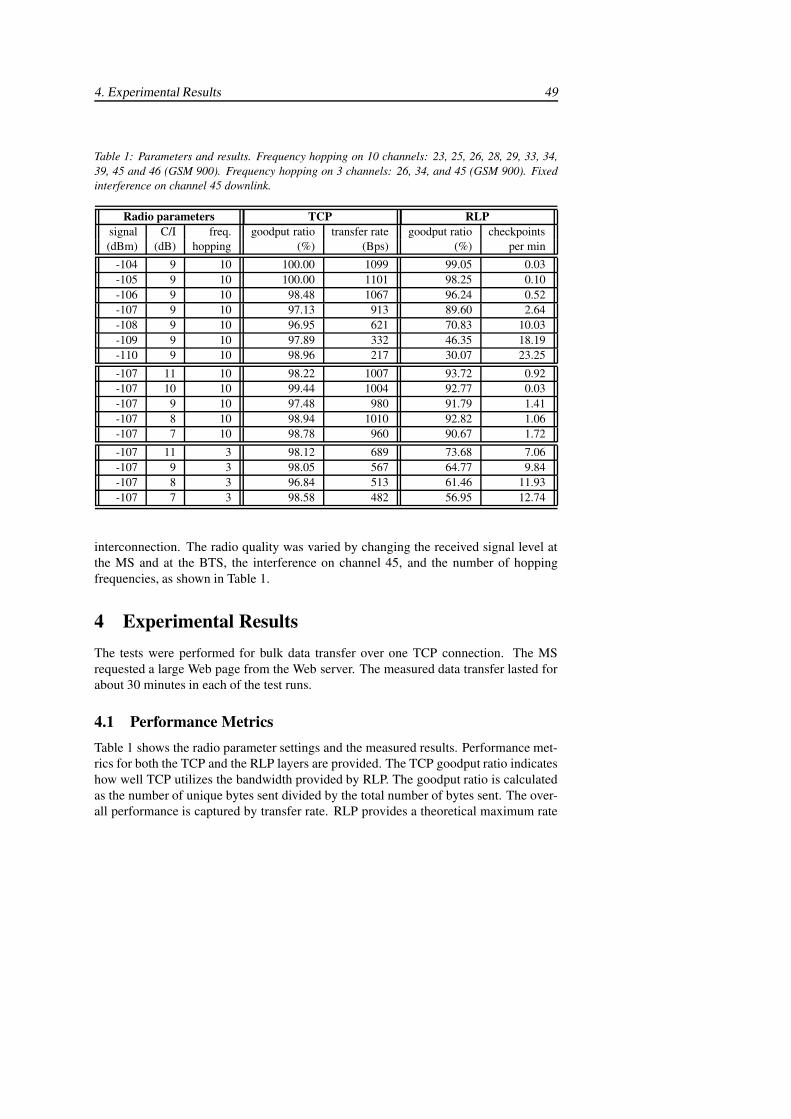
4. Experimental Results 49
Table 1: Parameters and results. Frequency hopping on 10 channels: 23, 25, 26, 28, 29, 33, 34,39, 45 and 46 (GSM 900). Frequency hopping on 3 channels: 26, 34, and 45 (GSM 900). Fixedinterference on channel 45 downlink.
Radio parameters TCP RLPsignal C/I freq. goodput ratio transfer rate goodput ratio checkpoints(dBm) (dB) hopping (%) (Bps) (%) per min
-104 9 10 100.00 1099 99.05 0.03-105 9 10 100.00 1101 98.25 0.10-106 9 10 98.48 1067 96.24 0.52-107 9 10 97.13 913 89.60 2.64-108 9 10 96.95 621 70.83 10.03-109 9 10 97.89 332 46.35 18.19-110 9 10 98.96 217 30.07 23.25
-107 11 10 98.22 1007 93.72 0.92-107 10 10 99.44 1004 92.77 0.03-107 9 10 97.48 980 91.79 1.41-107 8 10 98.94 1010 92.82 1.06-107 7 10 98.78 960 90.67 1.72
-107 11 3 98.12 689 73.68 7.06-107 9 3 98.05 567 64.77 9.84-107 8 3 96.84 513 61.46 11.93-107 7 3 98.58 482 56.95 12.74
interconnection. The radio quality was varied by changing the received signal level atthe MS and at the BTS, the interference on channel 45, and the number of hoppingfrequencies, as shown in Table 1.
4 Experimental ResultsThe tests were performed for bulk data transfer over one TCP connection. The MSrequested a large Web page from the Web server. The measured data transfer lasted forabout 30 minutes in each of the test runs.
4.1 Performance MetricsTable 1 shows the radio parameter settings and the measured results. Performance met-rics for both the TCP and the RLP layers are provided. The TCP goodput ratio indicateshow well TCP utilizes the bandwidth provided by RLP. The goodput ratio is calculatedas the number of unique bytes sent divided by the total number of bytes sent. The over-all performance is captured by transfer rate. RLP provides a theoretical maximum rate
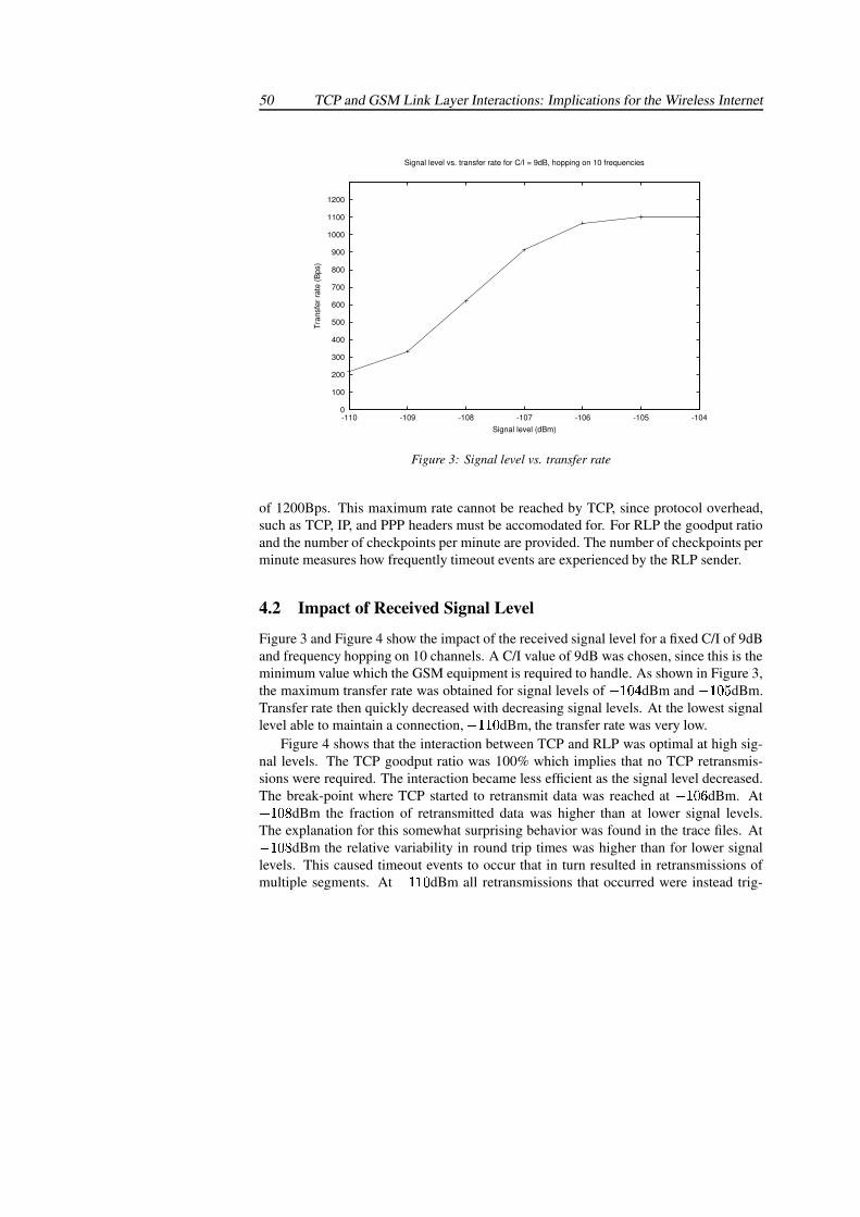
50 TCP and GSM Link Layer Interactions: Implications for the Wireless Internet
0
100
200
300
400
500
600
700
800
900
1000
1100
1200
-110 -109 -108 -107 -106 -105 -104
Tran
sfer
rate
(Bps
)
Signal level (dBm)
Signal level vs. transfer rate for C/I = 9dB, hopping on 10 frequencies
Figure 3: Signal level vs. transfer rate
of 1200Bps. This maximum rate cannot be reached by TCP, since protocol overhead,such as TCP, IP, and PPP headers must be accomodated for. For RLP the goodput ratioand the number of checkpoints per minute are provided. The number of checkpoints perminute measures how frequently timeout events are experienced by the RLP sender.
4.2 Impact of Received Signal Level
Figure 3 and Figure 4 show the impact of the received signal level for a fixed C/I of 9dBand frequency hopping on 10 channels. A C/I value of 9dB was chosen, since this is theminimum value which the GSM equipment is required to handle. As shown in Figure 3,the maximum transfer rate was obtained for signal levels of ������ dBm and ������ dBm.Transfer rate then quickly decreased with decreasing signal levels. At the lowest signallevel able to maintain a connection, ������� dBm, the transfer rate was very low.
Figure 4 shows that the interaction between TCP and RLP was optimal at high sig-nal levels. The TCP goodput ratio was 100% which implies that no TCP retransmis-sions were required. The interaction became less efficient as the signal level decreased.The break-point where TCP started to retransmit data was reached at ������ dBm. At������� dBm the fraction of retransmitted data was higher than at lower signal levels.The explanation for this somewhat surprising behavior was found in the trace files. At������� dBm the relative variability in round trip times was higher than for lower signallevels. This caused timeout events to occur that in turn resulted in retransmissions ofmultiple segments. At ������� dBm all retransmissions that occurred were instead trig-
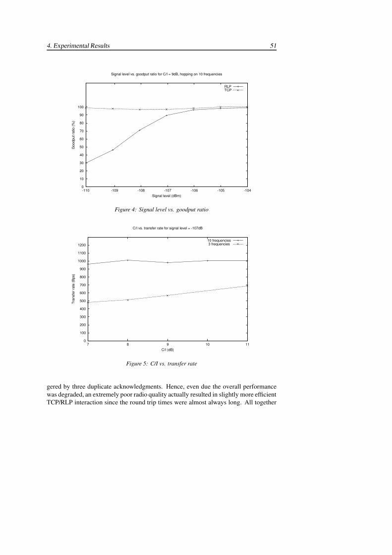
4. Experimental Results 51
0
10
20
30
40
50
60
70
80
90
100
-110 -109 -108 -107 -106 -105 -104
Goo
dput
ratio
(%)
Signal level (dBm)
Signal level vs. goodput ratio for C/I = 9dB, hopping on 10 frequencies
RLPTCP
Figure 4: Signal level vs. goodput ratio
0
100
200
300
400
500
600
700
800
900
1000
1100
1200
7 8 9 10 11
Tran
sfer
rate
(Bps
)
C/I (dB)
C/I vs. transfer rate for signal level = -107dB
10 frequencies3 frequencies
Figure 5: C/I vs. transfer rate
gered by three duplicate acknowledgments. Hence, even due the overall performancewas degraded, an extremely poor radio quality actually resulted in slightly more efficientTCP/RLP interaction since the round trip times were almost always long. All together
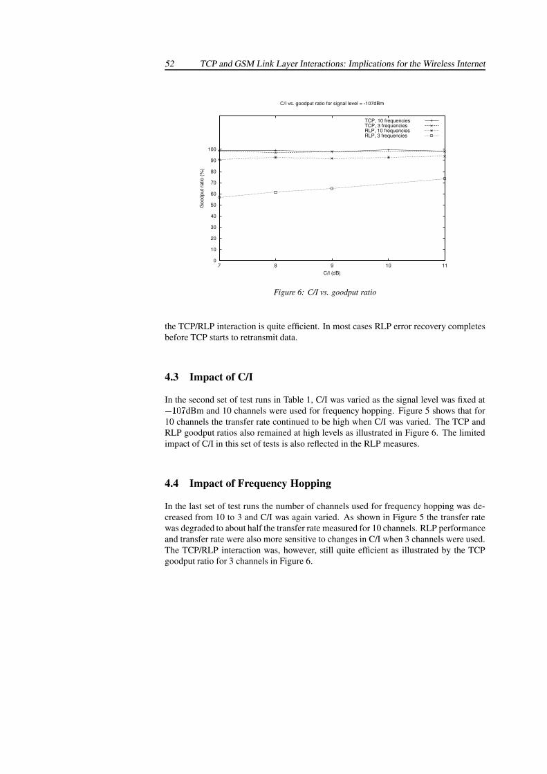
52 TCP and GSM Link Layer Interactions: Implications for the Wireless Internet
0
10
20
30
40
50
60
70
80
90
100
7 8 9 10 11
Goo
dput
ratio
(%)
C/I (dB)
C/I vs. goodput ratio for signal level = -107dBm
TCP, 10 frequenciesTCP, 3 frequenciesRLP, 10 frequenciesRLP, 3 frequencies
Figure 6: C/I vs. goodput ratio
the TCP/RLP interaction is quite efficient. In most cases RLP error recovery completesbefore TCP starts to retransmit data.
4.3 Impact of C/I
In the second set of test runs in Table 1, C/I was varied as the signal level was fixed at������� dBm and 10 channels were used for frequency hopping. Figure 5 shows that for10 channels the transfer rate continued to be high when C/I was varied. The TCP andRLP goodput ratios also remained at high levels as illustrated in Figure 6. The limitedimpact of C/I in this set of tests is also reflected in the RLP measures.
4.4 Impact of Frequency Hopping
In the last set of test runs the number of channels used for frequency hopping was de-creased from 10 to 3 and C/I was again varied. As shown in Figure 5 the transfer ratewas degraded to about half the transfer rate measured for 10 channels. RLP performanceand transfer rate were also more sensitive to changes in C/I when 3 channels were used.The TCP/RLP interaction was, however, still quite efficient as illustrated by the TCPgoodput ratio for 3 channels in Figure 6.
REFERENCES 53
4.5 Discussion
The measurements show that the interaction between TCP and RLP was efficient formost radio parameter settings tested. No significant correlation was observed betweenlow throughput and a high degree of inefficient layer interaction. The decrease in TCPthroughput as the radio conditions worsened could not be attributed to an increasingnumber of competeing retransmissions. The most inefficient interaction appeared forradio parameter settings that resulted in the highest relative variability in round triptimes rather than in the poorest radio conditions.
When implementing the future wireless Internet, the results show that it is quitepossible to have wireless link layers that work well with an unmodified TCP. However,in the quest for more spectrum efficiency new problems arise. If future wireless systemslower the FEC strength more link layer retransmissions will occur. The results provide ahint that this can be problematic for TCP depending on the distribution of the link layerretransmission delays. As long as the delays vary within in the timescale used by theTCP RTO calculation it is not probable that the variation will be a significant problem.However, the radio conditions and the link layer design can produce delay variationsthat are too spurious. In this context, too spurious means that the RTO inflation due toone large delay has decreasead when the next large delay occurs. This leads to a TCPtimeout while the link layer retransmits, which adversely affects the goodput.
One possible solution to control delay at the link layer and prevent inefficient multi-layer retransmissions is to bound the time available for retransmissions at the link layer.If the link layer cannot succesfully recover the lost data within the bounded time, then atransport layer retransmission can be used to recover the data. The relation between linklayer frame size and segment size then becomes significant. Retransmitting a large TCPsegment when a small link layer frame has reached its retransmission time bound wouldclearly be inefficient if the frame can be retransmitted without causing a TCP timeout.
5 Concluding RemarksThe measurements show that TCP and GSM RLP coexist peacefully. The system designused for the future wireless Internet infrastructure can, however, be expected to tradeincreased spectrum efficiency for increased error rates at the link layer. The impactof this on the interaction between the link layer and TCP is not fully understood andsomething we intend to study further.
References[1] T. Alanko, M. Kojo, H. Laamanen, M. Liljeberg, M. Moilanen, and K. Raatikainen.
Measured performance of data transmission over cellular telephone networks. ACMComputer Communication Review, 24(5), 1994.
54 TCP and GSM Link Layer Interactions: Implications for the Wireless Internet
[2] Ethereal. A network protocol analyzer. http://www.ethereal.com/.
[3] ETSI. Digital cellular telecommunications system (Phase 2+); Radio Link Protocol(RLP) for data and telematic services on the Mobile Station - Base Station System(MS - BSS) interface and the Base Station System - Mobile-services SwitchingCentre (BSS - MSC) interface (GSM 04.22 version 7.0.1 Release 1998). ETSI,1999.
[4] R. Ludwig. Eliminating inefficient cross-layer interactions in wireless networking.Ph.D. Thesis, Aachen University of Technology, Germany, April 2000.
[5] R. Ludwig, B. Rathonyi, A. Konrad, K. Oden, and A. Joseph. Multi-layer tracing ofTCP over a reliable wireless link. ACM SIGMETRICS, 1999.
[6] M. Mathis, J. Mahdavi, S. Floyd, and A. Romanow. RFC 2018: TCP selectiveacknowledgment options, October 1996.
[7] S. Ostermann. Tcptrace. http://www.tcptrace.org/.
[8] J. Postel. RFC 793: Transmission control protocol, September 1981.
Paper III
A GSM/GPRS Testbed for TCP Performance Evaluation
Reprinted from
Proceedings of International Workshop on Wired/Wireless Internet Communications(WWIC 2002)
Las Vegas, USA, June 2002.

A GSM/GPRS Testbed for TCP PerformanceEvaluation
Annika Wennstrom, Anna Brunstrom, Johan GarciaDept. of Computer Science
Karlstad UniversitySE-651 88 Karlstad, Sweden�
Annika.Wennstrom, Anna Brunstrom, Johan.Garcia � @kau.se
Jan H. GustafssonTelia Mobile ABLagergrens gata 7
SE-651 15 Karlstad, [email protected]
Abstract
Investigating the wireless Internet is a nontrivial task due to the complexity ofwireless systems and the many protocol interactions that appear. In this paper wepresent a measurement testbed that allows us to investigate the performance of In-ternet traffic over a real GSM network but with a controlled radio environment andtraffic load. A detailed performance evaluation of TCP over GSM is presented. Arange of radio conditions are considered with a focus on the interaction betweenTCP and the GSM link layer. With respect to efficient protocol layer interaction,the results show that high variability in round trip times is more problematic thanpoor radio conditions. How the testbed has been extended for GPRS and plannedmeasurements for this system are also discussed.
1 IntroductionDue to the growing importance of wireless Internet applications, much attention hasbeen given to the performance of TCP in wireless networks. Performing relevant per-formance studies of TCP in wireless networks is, however, a challenging task due to thecomplexity of the underlying network technologies and the large number of differentprotocols involved in the communication.
Simulation studies provide full control over all the parameters involved in the studyand allow exploration over a wide range of parameters and parameter settings. Simula-tions that use general models of wireless networks can provide valuable insight into theoperation of TCP under various conditions. The applicability of the results to a specific
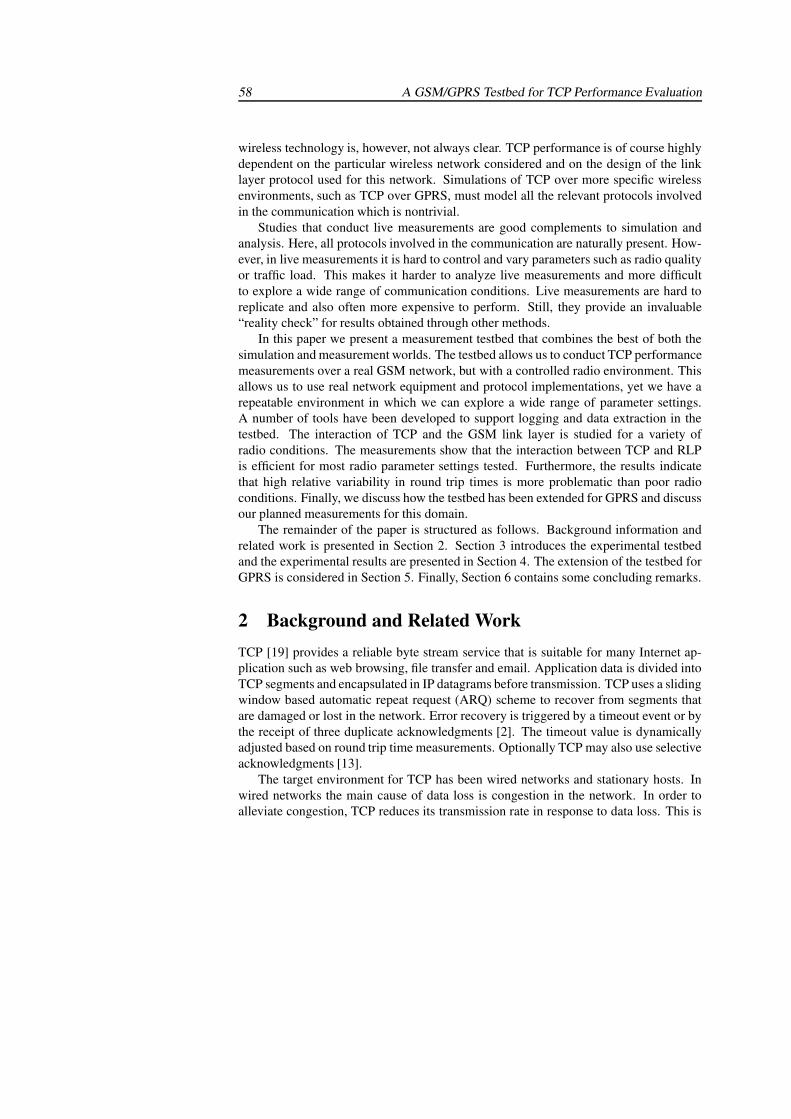
58 A GSM/GPRS Testbed for TCP Performance Evaluation
wireless technology is, however, not always clear. TCP performance is of course highlydependent on the particular wireless network considered and on the design of the linklayer protocol used for this network. Simulations of TCP over more specific wirelessenvironments, such as TCP over GPRS, must model all the relevant protocols involvedin the communication which is nontrivial.
Studies that conduct live measurements are good complements to simulation andanalysis. Here, all protocols involved in the communication are naturally present. How-ever, in live measurements it is hard to control and vary parameters such as radio qualityor traffic load. This makes it harder to analyze live measurements and more difficultto explore a wide range of communication conditions. Live measurements are hard toreplicate and also often more expensive to perform. Still, they provide an invaluable“reality check” for results obtained through other methods.
In this paper we present a measurement testbed that combines the best of both thesimulation and measurement worlds. The testbed allows us to conduct TCP performancemeasurements over a real GSM network, but with a controlled radio environment. Thisallows us to use real network equipment and protocol implementations, yet we have arepeatable environment in which we can explore a wide range of parameter settings.A number of tools have been developed to support logging and data extraction in thetestbed. The interaction of TCP and the GSM link layer is studied for a variety ofradio conditions. The measurements show that the interaction between TCP and RLPis efficient for most radio parameter settings tested. Furthermore, the results indicatethat high relative variability in round trip times is more problematic than poor radioconditions. Finally, we discuss how the testbed has been extended for GPRS and discussour planned measurements for this domain.
The remainder of the paper is structured as follows. Background information andrelated work is presented in Section 2. Section 3 introduces the experimental testbedand the experimental results are presented in Section 4. The extension of the testbed forGPRS is considered in Section 5. Finally, Section 6 contains some concluding remarks.
2 Background and Related WorkTCP [19] provides a reliable byte stream service that is suitable for many Internet ap-plication such as web browsing, file transfer and email. Application data is divided intoTCP segments and encapsulated in IP datagrams before transmission. TCP uses a slidingwindow based automatic repeat request (ARQ) scheme to recover from segments thatare damaged or lost in the network. Error recovery is triggered by a timeout event or bythe receipt of three duplicate acknowledgments [2]. The timeout value is dynamicallyadjusted based on round trip time measurements. Optionally TCP may also use selectiveacknowledgments [13].
The target environment for TCP has been wired networks and stationary hosts. Inwired networks the main cause of data loss is congestion in the network. In order toalleviate congestion, TCP reduces its transmission rate in response to data loss. This is
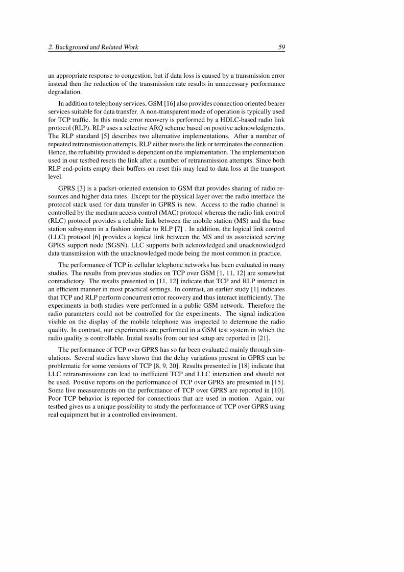
2. Background and Related Work 59
an appropriate response to congestion, but if data loss is caused by a transmission errorinstead then the reduction of the transmission rate results in unnecessary performancedegradation.
In addition to telephony services, GSM [16] also provides connection oriented bearerservices suitable for data transfer. A non-transparent mode of operation is typically usedfor TCP traffic. In this mode error recovery is performed by a HDLC-based radio linkprotocol (RLP). RLP uses a selective ARQ scheme based on positive acknowledgments.The RLP standard [5] describes two alternative implementations. After a number ofrepeated retransmission attempts, RLP either resets the link or terminates the connection.Hence, the reliability provided is dependent on the implementation. The implementationused in our testbed resets the link after a number of retransmission attempts. Since bothRLP end-points empty their buffers on reset this may lead to data loss at the transportlevel.
GPRS [3] is a packet-oriented extension to GSM that provides sharing of radio re-sources and higher data rates. Except for the physical layer over the radio interface theprotocol stack used for data transfer in GPRS is new. Access to the radio channel iscontrolled by the medium access control (MAC) protocol whereas the radio link control(RLC) protocol provides a reliable link between the mobile station (MS) and the basestation subsystem in a fashion similar to RLP [7] . In addition, the logical link control(LLC) protocol [6] provides a logical link between the MS and its associated servingGPRS support node (SGSN). LLC supports both acknowledged and unacknowledgeddata transmission with the unacknowledged mode being the most common in practice.
The performance of TCP in cellular telephone networks has been evaluated in manystudies. The results from previous studies on TCP over GSM [1, 11, 12] are somewhatcontradictory. The results presented in [11, 12] indicate that TCP and RLP interact inan efficient manner in most practical settings. In contrast, an earlier study [1] indicatesthat TCP and RLP perform concurrent error recovery and thus interact inefficiently. Theexperiments in both studies were performed in a public GSM network. Therefore theradio parameters could not be controlled for the experiments. The signal indicationvisible on the display of the mobile telephone was inspected to determine the radioquality. In contrast, our experiments are performed in a GSM test system in which theradio quality is controllable. Initial results from our test setup are reported in [21].
The performance of TCP over GPRS has so far been evaluated mainly through sim-ulations. Several studies have shown that the delay variations present in GPRS can beproblematic for some versions of TCP [8, 9, 20]. Results presented in [18] indicate thatLLC retransmissions can lead to inefficient TCP and LLC interaction and should notbe used. Positive reports on the performance of TCP over GPRS are presented in [15].Some live measurements on the performance of TCP over GPRS are reported in [10].Poor TCP behavior is reported for connections that are used in motion. Again, ourtestbed gives us a unique possibility to study the performance of TCP over GPRS usingreal equipment but in a controlled environment.
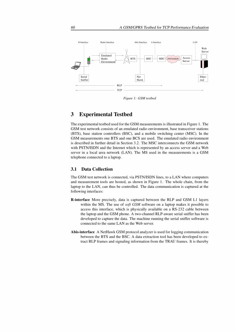
60 A GSM/GPRS Testbed for TCP Performance Evaluation
SerialSniffer
R Interface Abis Interface
NetHawk
AccessServer
A Interface
MSCBSC
Radio Interface
EmulatedRadioEnvironment
PSTN/ISDN
WebServer
RLP
TCP
LAN
realEther-
BTS
Figure 1: GSM testbed
3 Experimental TestbedThe experimental testbed used for the GSM measurements is illustrated in Figure 1. TheGSM test network consists of an emulated radio environment, base transceiver stations(BTS), base station controllers (BSC), and a mobile switching center (MSC). In theGSM measurements one BTS and one BCS are used. The emulated radio environmentis described in further detail in Section 3.2. The MSC interconnects the GSM networkwith PSTN/ISDN and the Internet which is represented by an access server and a Webserver in a local area network (LAN). The MS used in the measurements is a GSMtelephone connected to a laptop.
3.1 Data Collection
The GSM test network is connected, via PSTN/ISDN lines, to a LAN where computersand measurement tools are hosted, as shown in Figure 1. The whole chain, from thelaptop to the LAN, can thus be controlled. The data communication is captured at thefollowing interfaces:
R-interface More precisely, data is captured between the RLP and GSM L1 layerswithin the MS. The use of soft GSM software on a laptop makes it possible toaccess this interface, which is physically available on a RS-232 cable betweenthe laptop and the GSM phone. A two-channel RLP-aware serial sniffer has beendeveloped to capture the data. The machine running the serial sniffer software isconnected to the same LAN as the Web server.
Abis-interface A NetHawk GSM protocol analyzer is used for logging communicationbetween the BTS and the BSC. A data extraction tool has been developed to ex-tract RLP frames and signaling information from the TRAU frames. It is thereby
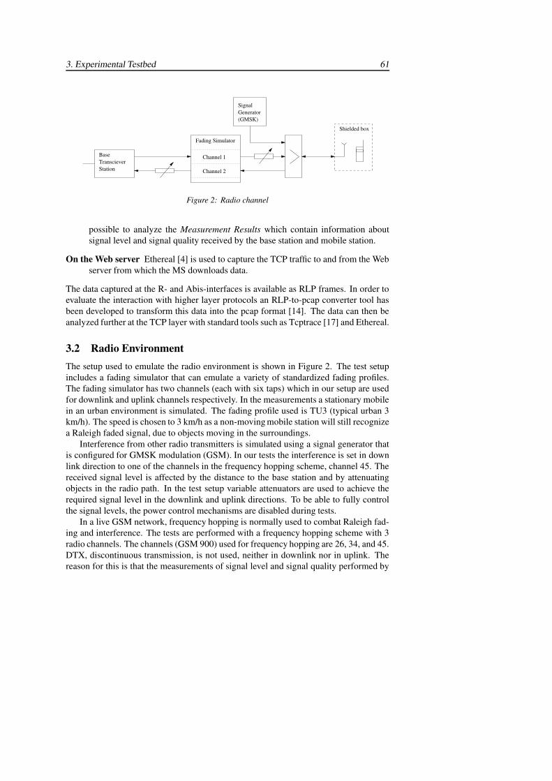
3. Experimental Testbed 61
BaseTranscieverStation
Fading Simulator
Channel 2
Channel 1
SignalGenerator(GMSK)
Shielded box
Figure 2: Radio channel
possible to analyze the Measurement Results which contain information aboutsignal level and signal quality received by the base station and mobile station.
On the Web server Ethereal [4] is used to capture the TCP traffic to and from the Webserver from which the MS downloads data.
The data captured at the R- and Abis-interfaces is available as RLP frames. In order toevaluate the interaction with higher layer protocols an RLP-to-pcap converter tool hasbeen developed to transform this data into the pcap format [14]. The data can then beanalyzed further at the TCP layer with standard tools such as Tcptrace [17] and Ethereal.
3.2 Radio EnvironmentThe setup used to emulate the radio environment is shown in Figure 2. The test setupincludes a fading simulator that can emulate a variety of standardized fading profiles.The fading simulator has two channels (each with six taps) which in our setup are usedfor downlink and uplink channels respectively. In the measurements a stationary mobilein an urban environment is simulated. The fading profile used is TU3 (typical urban 3km/h). The speed is chosen to 3 km/h as a non-moving mobile station will still recognizea Raleigh faded signal, due to objects moving in the surroundings.
Interference from other radio transmitters is simulated using a signal generator thatis configured for GMSK modulation (GSM). In our tests the interference is set in downlink direction to one of the channels in the frequency hopping scheme, channel 45. Thereceived signal level is affected by the distance to the base station and by attenuatingobjects in the radio path. In the test setup variable attenuators are used to achieve therequired signal level in the downlink and uplink directions. To be able to fully controlthe signal levels, the power control mechanisms are disabled during tests.
In a live GSM network, frequency hopping is normally used to combat Raleigh fad-ing and interference. The tests are performed with a frequency hopping scheme with 3radio channels. The channels (GSM 900) used for frequency hopping are 26, 34, and 45.DTX, discontinuous transmission, is not used, neither in downlink nor in uplink. Thereason for this is that the measurements of signal level and signal quality performed by
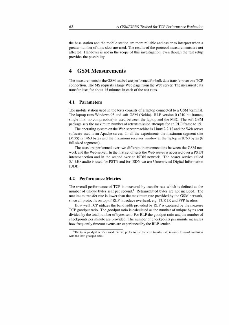
62 A GSM/GPRS Testbed for TCP Performance Evaluation
the base station and the mobile station are more reliable and easier to interpret when agreater number of time slots are used. The results of the protocol measurements are notaffected. Handover is not in the scope of this investigation, even though the test setupprovides the possibility.
4 GSM Measurements
The measurements in the GSM testbed are performed for bulk data transfer over one TCPconnection. The MS requests a large Web page from the Web server. The measured datatransfer lasts for about 15 minutes in each of the test runs.
4.1 Parameters
The mobile station used in the tests consists of a laptop connected to a GSM terminal.The laptop runs Windows 95 and soft GSM (Nokia). RLP version 0 (240-bit frames,single-link, no compression) is used between the laptop and the MSC. The soft GSMpackage sets the maximum number of retransmission attempts for an RLP frame to 15.
The operating system on the Web server machine is Linux 2.2.12 and the Web serversoftware used is an Apache server. In all the experiments the maximum segment size(MSS) is 1460 bytes and the maximum receiver window at the laptop is 8760 bytes (6full sized segments).
The tests are performed over two different interconnections between the GSM net-work and the Web server. In the first set of tests the Web server is accessed over a PSTNinterconnection and in the second over an ISDN network. The bearer service called3.1 kHz audio is used for PSTN and for ISDN we use Unrestricted Digital Information(UDI).
4.2 Performance Metrics
The overall performance of TCP is measured by transfer rate which is defined as thenumber of unique bytes sent per second.1 Retransmitted bytes are not included. Themaximum transfer rate is lower than the maximum rate provided by the GSM network,since all protocols on top of RLP introduce overhead, e.g. TCP, IP, and PPP headers.
How well TCP utilizes the bandwidth provided by RLP is captured by the measureTCP goodput ratio. The goodput ratio is calculated as the number of unique bytes sentdivided by the total number of bytes sent. For RLP the goodput ratio and the number ofcheckpoints per minute are provided. The number of checkpoints per minute measureshow frequently timeout events are experienced by the RLP sender.
1The term goodput is often used, but we prefer to use the term transfer rate in order to avoid confusionwith the term goodput ratio.
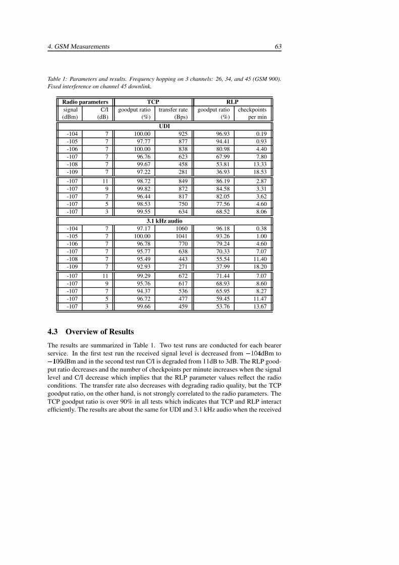
4. GSM Measurements 63
Table 1: Parameters and results. Frequency hopping on 3 channels: 26, 34, and 45 (GSM 900).Fixed interference on channel 45 downlink.
Radio parameters TCP RLPsignal C/I goodput ratio transfer rate goodput ratio checkpoints(dBm) (dB) (%) (Bps) (%) per min
UDI-104 7 100.00 925 96.93 0.19-105 7 97.77 877 94.41 0.93-106 7 100.00 838 80.98 4.40-107 7 96.76 623 67.99 7.80-108 7 99.67 458 53.81 13.33-109 7 97.22 281 36.93 18.53
-107 11 98.72 849 86.19 2.87-107 9 99.82 872 84.58 3.31-107 7 96.44 817 82.05 3.62-107 5 98.53 750 77.56 4.60-107 3 99.55 634 68.52 8.06
3.1 kHz audio-104 7 97.17 1060 96.18 0.38-105 7 100.00 1041 93.26 1.00-106 7 96.78 770 79.24 4.60-107 7 95.77 638 70.33 7.07-108 7 95.49 443 55.54 11.40-109 7 92.93 271 37.99 18.20
-107 11 99.29 672 71.44 7.07-107 9 95.76 617 68.93 8.60-107 7 94.37 536 65.95 8.27-107 5 96.72 477 59.45 11.47-107 3 99.66 459 53.76 13.67
4.3 Overview of Results
The results are summarized in Table 1. Two test runs are conducted for each bearerservice. In the first test run the received signal level is decreased from ������ dBm to������� dBm and in the second test run C/I is degraded from 11dB to 3dB. The RLP good-put ratio decreases and the number of checkpoints per minute increases when the signallevel and C/I decrease which implies that the RLP parameter values reflect the radioconditions. The transfer rate also decreases with degrading radio quality, but the TCPgoodput ratio, on the other hand, is not strongly correlated to the radio parameters. TheTCP goodput ratio is over 90% in all tests which indicates that TCP and RLP interactefficiently. The results are about the same for UDI and 3.1 kHz audio when the received
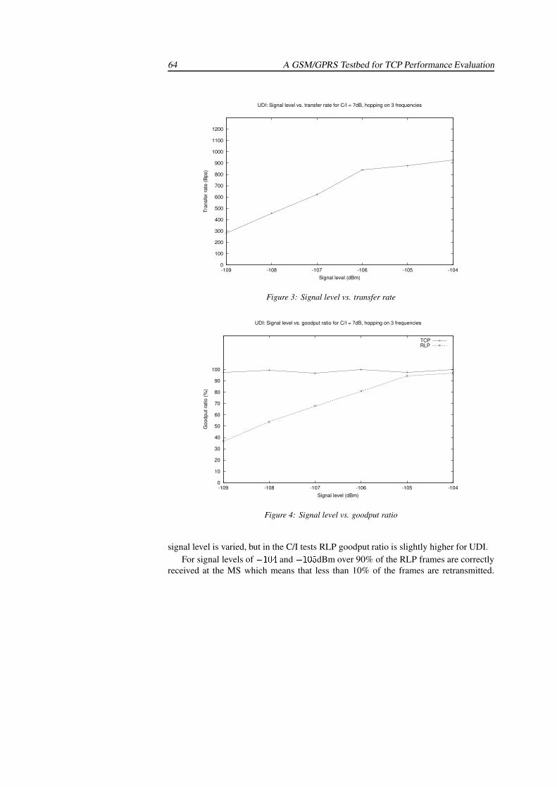
64 A GSM/GPRS Testbed for TCP Performance Evaluation
0
100
200
300
400
500
600
700
800
900
1000
1100
1200
-109 -108 -107 -106 -105 -104
Tran
sfer
rate
(Bps
)
Signal level (dBm)
UDI: Signal level vs. transfer rate for C/I = 7dB, hopping on 3 frequencies
Figure 3: Signal level vs. transfer rate
0
10
20
30
40
50
60
70
80
90
100
-109 -108 -107 -106 -105 -104
Goo
dput
ratio
(%)
Signal level (dBm)
UDI: Signal level vs. goodput ratio for C/I = 7dB, hopping on 3 frequencies
TCPRLP
Figure 4: Signal level vs. goodput ratio
signal level is varied, but in the C/I tests RLP goodput ratio is slightly higher for UDI.For signal levels of ������ and ������ dBm over 90% of the RLP frames are correctly
received at the MS which means that less than 10% of the frames are retransmitted.
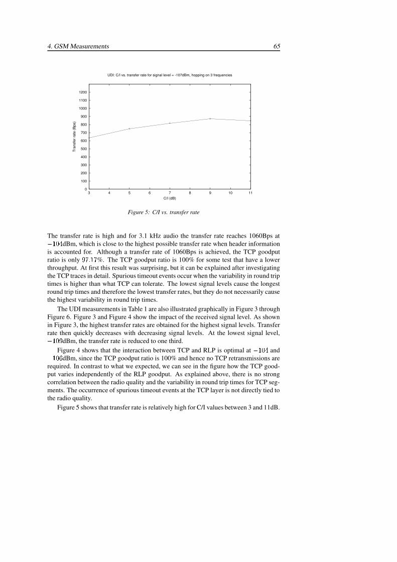
4. GSM Measurements 65
0
100
200
300
400
500
600
700
800
900
1000
1100
1200
3 4 5 6 7 8 9 10 11
Tran
sfer
rate
(Bps
)
C/I (dB)
UDI: C/I vs. transfer rate for signal level = -107dBm, hopping on 3 frequencies
Figure 5: C/I vs. transfer rate
The transfer rate is high and for 3.1 kHz audio the transfer rate reaches 1060Bps at������ dBm, which is close to the highest possible transfer rate when header informationis accounted for. Although a transfer rate of 1060Bps is achieved, the TCP goodputratio is only ��������� %. The TCP goodput ratio is 100% for some test that have a lowerthroughput. At first this result was surprising, but it can be explained after investigatingthe TCP traces in detail. Spurious timeout events occur when the variability in round triptimes is higher than what TCP can tolerate. The lowest signal levels cause the longestround trip times and therefore the lowest transfer rates, but they do not necessarily causethe highest variability in round trip times.
The UDI measurements in Table 1 are also illustrated graphically in Figure 3 throughFigure 6. Figure 3 and Figure 4 show the impact of the received signal level. As shownin Figure 3, the highest transfer rates are obtained for the highest signal levels. Transferrate then quickly decreases with decreasing signal levels. At the lowest signal level,������� dBm, the transfer rate is reduced to one third.
Figure 4 shows that the interaction between TCP and RLP is optimal at ������ and������ dBm, since the TCP goodput ratio is 100% and hence no TCP retransmissions arerequired. In contrast to what we expected, we can see in the figure how the TCP good-put varies independently of the RLP goodput. As explained above, there is no strongcorrelation between the radio quality and the variability in round trip times for TCP seg-ments. The occurrence of spurious timeout events at the TCP layer is not directly tied tothe radio quality.
Figure 5 shows that transfer rate is relatively high for C/I values between 3 and 11dB.
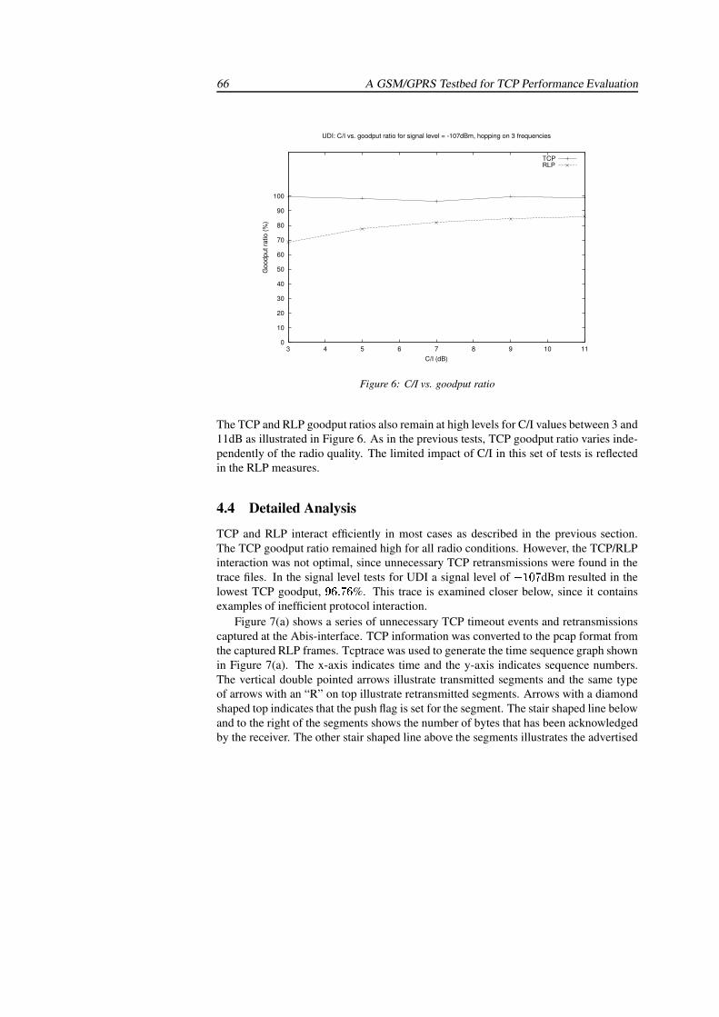
66 A GSM/GPRS Testbed for TCP Performance Evaluation
0
10
20
30
40
50
60
70
80
90
100
3 4 5 6 7 8 9 10 11
Goo
dput
ratio
(%)
C/I (dB)
UDI: C/I vs. goodput ratio for signal level = -107dBm, hopping on 3 frequencies
TCPRLP
Figure 6: C/I vs. goodput ratio
The TCP and RLP goodput ratios also remain at high levels for C/I values between 3 and11dB as illustrated in Figure 6. As in the previous tests, TCP goodput ratio varies inde-pendently of the radio quality. The limited impact of C/I in this set of tests is reflectedin the RLP measures.
4.4 Detailed Analysis
TCP and RLP interact efficiently in most cases as described in the previous section.The TCP goodput ratio remained high for all radio conditions. However, the TCP/RLPinteraction was not optimal, since unnecessary TCP retransmissions were found in thetrace files. In the signal level tests for UDI a signal level of ������� dBm resulted in thelowest TCP goodput, �� ����� %. This trace is examined closer below, since it containsexamples of inefficient protocol interaction.
Figure 7(a) shows a series of unnecessary TCP timeout events and retransmissionscaptured at the Abis-interface. TCP information was converted to the pcap format fromthe captured RLP frames. Tcptrace was used to generate the time sequence graph shownin Figure 7(a). The x-axis indicates time and the y-axis indicates sequence numbers.The vertical double pointed arrows illustrate transmitted segments and the same typeof arrows with an “R” on top illustrate retransmitted segments. Arrows with a diamondshaped top indicates that the push flag is set for the segment. The stair shaped line belowand to the right of the segments shows the number of bytes that has been acknowledgedby the receiver. The other stair shaped line above the segments illustrates the advertised
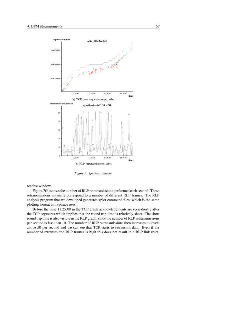
4. GSM Measurements 67
1666820000
1666800000
1666780000
11:26:30 11:26:00 11:25:30 11:25:00
sequence number
time
Abis, -107dBm, 7dB
��
��RRRR
�RR�R
3
RRR�
��
�
(a) TCP time sequence graph, Abis
50
40
30
20
10
0 11:26:30 11:26:00 11:25:30 11:25:00
retransmissions/second
time
signal level = -107, C/I = 7dB
(b) RLP retransmissions, Abis
Figure 7: Spurious timeout
receive window.Figure 7(b) shows the number of RLP retransmissions performed each second. These
retransmissions normally correspond to a number of different RLP frames. The RLPanalysis program that we developed generates xplot command files, which is the sameplotting format as Tcptrace uses.
Before the time 11:25:00 in the TCP graph acknowledgments are seen shortly afterthe TCP segments which implies that the round trip time is relatively short. The shortround trip time is also visible in the RLP graph, since the number of RLP retransmissionsper second is less than 10. The number of RLP retransmissions then increases to levelsabove 50 per second and we can see that TCP starts to retransmit data. Even if thenumber of retransmitted RLP frames is high this does not result in a RLP link reset,
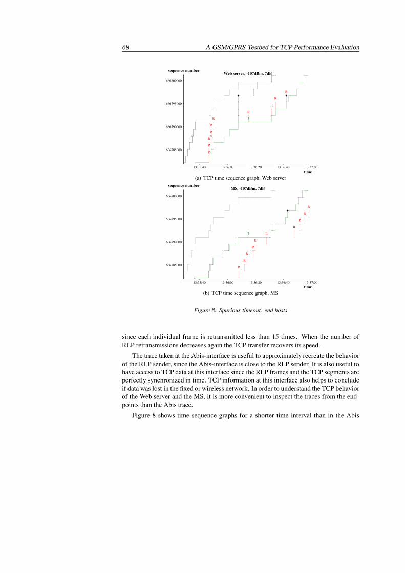
68 A GSM/GPRS Testbed for TCP Performance Evaluation
1666800000
1666795000
1666790000
1666785000
13:37:00 13:36:40 13:36:20 13:36:00 13:35:40
sequence number
time
Web server, -107dBm, 7dB
�RR
R
R
3
�
R
R
�RR
R
R
�
(a) TCP time sequence graph, Web server
1666800000
1666795000
1666790000
1666785000
13:37:00 13:36:40 13:36:20 13:36:00 13:35:40
sequence number
time
MS, -107dBm, 7dB
�RR
R
R
�
R
R
�R3
R
R
R
�
(b) TCP time sequence graph, MS
Figure 8: Spurious timeout: end hosts
since each individual frame is retransmitted less than 15 times. When the number ofRLP retransmissions decreases again the TCP transfer recovers its speed.
The trace taken at the Abis-interface is useful to approximately recreate the behaviorof the RLP sender, since the Abis-interface is close to the RLP sender. It is also useful tohave access to TCP data at this interface since the RLP frames and the TCP segments areperfectly synchronized in time. TCP information at this interface also helps to concludeif data was lost in the fixed or wireless network. In order to understand the TCP behaviorof the Web server and the MS, it is more convenient to inspect the traces from the end-points than the Abis trace.
Figure 8 shows time sequence graphs for a shorter time interval than in the Abis
5. GPRS Measurements 69
graph.2 Ethereal was used to capture TCP traffic at the Web server and at the MS TCPdata was extracted from the RLP frames. The Web server experiences timeout eventsand retransmits several segments as shown in Figure 8(a). From this trace it is unclearwhether the original segments or the retransmissions are acknowledged. In this case theMS trace in Figure 8(b) is helpful. The figure shows the same number of retransmit-ted segments as in the previous time sequence graph for the Web server. We can seein the figure from the MS trace that the original segments are acknowledged, not theretransmissions. Acknowledgments are transmitted just after the original segments arereceived. By examining both the Web server and the MS traces it is clear that all retrans-missions shown in the graphs are unnecessary and degrade the TCP goodput ratio.
5 GPRS Measurements
The experimental environment has been extended for GPRS measurements as shownin Figure 9. New nodes are added to the test network, a SGSN and a gateway GPRSsupport node (GGSN). The MSC, the access server, and the access network that areused to interconnect the GSM network to the Internet are unnecessary in GPRS sincethey are replaced by a GGSN instead.
As for the GSM measurements, Ethereal is used to capture traffic at the Web serverand the NewHawk protocol analyzer collects data at the Abis-interface. The link layerprotocol used over the radio interface in GPRS, RLC/MAC, is not accessible on theR-interface, since the RLC/MAC connection terminates in the GPRS telephone. Someinformation about RLC/MAC can, however, still be obtained by using a GPRS telephonethat is especially designed for testing. The new tools that are required in order to analyzethe interaction between TCP and RLC/MAC include new tools to convert the NetHawklogs into pcap since the protocol stack is now different.
Measurements over the GPRS experimental environment has just been initiated. Thefirst set of measurements will investigate how TCP is affected by high priority traffic.Voice calls are commonly assigned higher priority than packet-switched traffic. Thus,the radio resources available for packet-switched traffic will vary over time. This couldlead to high variability in round trip times [8]. In the GSM measurements the interac-tion between TCP and RLP suffers the most when the radio conditions result in highlyvariable round trip times, as described in Section 4.4. In GPRS the fact that the radioresources available to GPRS users will change over time is an additional source of roundtrip time variations that may have a negative impact on the interaction between TCP andthe link layer protocol used in GPRS. Other events that occur in a GPRS network such ascell reselection and dynamic resource allocation may also cause high variability in roundtrip times. We plan to study the impact of both these events in later measurements.
2The difference in time as compared to the Abis graph is due to lack of clock synchronization between thelogging machines.
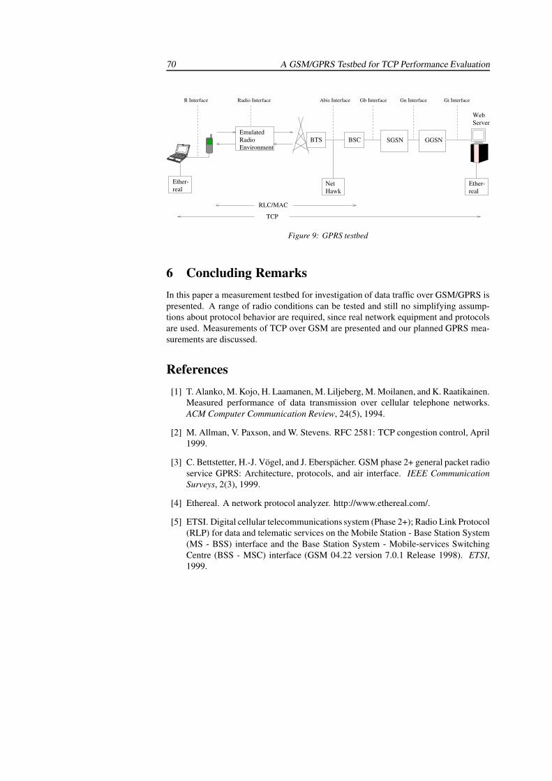
70 A GSM/GPRS Testbed for TCP Performance Evaluation
NetHawk
Abis Interface
BSC
WebServer
realEther-
Gi InterfaceGn InterfaceGb Interface
SGSN GGSN
realEther-
Radio Interface
EmulatedRadioEnvironment
BTS
R Interface
RLC/MAC
TCP
Figure 9: GPRS testbed
6 Concluding RemarksIn this paper a measurement testbed for investigation of data traffic over GSM/GPRS ispresented. A range of radio conditions can be tested and still no simplifying assump-tions about protocol behavior are required, since real network equipment and protocolsare used. Measurements of TCP over GSM are presented and our planned GPRS mea-surements are discussed.
References[1] T. Alanko, M. Kojo, H. Laamanen, M. Liljeberg, M. Moilanen, and K. Raatikainen.
Measured performance of data transmission over cellular telephone networks.ACM Computer Communication Review, 24(5), 1994.
[2] M. Allman, V. Paxson, and W. Stevens. RFC 2581: TCP congestion control, April1999.
[3] C. Bettstetter, H.-J. Vogel, and J. Eberspacher. GSM phase 2+ general packet radioservice GPRS: Architecture, protocols, and air interface. IEEE CommunicationSurveys, 2(3), 1999.
[4] Ethereal. A network protocol analyzer. http://www.ethereal.com/.
[5] ETSI. Digital cellular telecommunications system (Phase 2+); Radio Link Protocol(RLP) for data and telematic services on the Mobile Station - Base Station System(MS - BSS) interface and the Base Station System - Mobile-services SwitchingCentre (BSS - MSC) interface (GSM 04.22 version 7.0.1 Release 1998). ETSI,1999.
REFERENCES 71
[6] ETSI. Digital cellular telecommunications system (Phase 2+); General PacketRadio Service (GPRS); Mobile Station - Serving GPRS Support Node (MS-SGSN)Logical Link Control (LLC) layer specification (GSM 04.64 version 6.7.0 Release1997), 2000.
[7] ETSI. Digital cellular telecommunications system (Phase 2+); General Packet Ra-dio Service (GPRS); Mobile Station (MS) - Base Station System (BSS) interface;Radio Link Control/ Medium Access Control (RLC/MAC) protocol (GSM 04.60version 6.9.0 Release 1997), 2000. ETSI.
[8] A. Gurtov. Effect of delays on TCP performance. In Proceedings of IFIP PersonalWireless Communications, Lappeenranta, Finland, August 2001.
[9] A. Gurtov and R. Ludwig. Evaluating the Eifel algorithm for TCP in a GPRSnetwork. In Proceedings of European Wireless, Florence, Italy, February 2002.
[10] J. Korhonen, O. Aalto, A. Gurtov, and H. Laamanen. Measured performance ofGSM HSCSD and GPRS. In Proceedings of the IEEE Conference on Communi-cations, June 2001.
[11] R. Ludwig. Eliminating inefficient cross-layer interactions in wireless networking.Ph.D. Thesis, Aachen University of Technology, Germany, April 2000.
[12] R. Ludwig, B. Rathonyi, A. Konrad, K. Oden, and A. Joseph. Multi-layer tracingof TCP over a reliable wireless link. ACM SIGMETRICS, 1999.
[13] M. Mathis, J. Mahdavi, S. Floyd, and A. Romanow. RFC 2018: TCP selectiveacknowledgment options, October 1996.
[14] S. McCanne and V. Jacobson. The BSD packet filter: a new architecture for user-level packet capture. In Proceedings of the Winter 1993 USENIX Conference,pages 259–269, San Diego, California, USA, January 1993.
[15] M. Meyer. TCP performance over GPRS. In Proceedings of IEEE Wireless Com-munications and Networking Conference (WCNC ’99), volume 3, pages 1248–1252, New Orleans, Louisiana, USA, September 1999.
[16] M. Mouly and M.-B. Pautet. The GSM System for Mobile Communications. Cell& Sys, 1992.
[17] S. Ostermann. Tcptrace. http://www.tcptrace.org/.
[18] Q. Pang, A. Bigloo, V. Leung, and C. Scholefield. Performance evaluation of re-transmission mechanisms in GPRS networks. In Proceedings of IEEE WirelessCommunications and Networking Conference (WCNC’00), Chicago, IL, Septem-ber 2000.
72 A GSM/GPRS Testbed for TCP Performance Evaluation
[19] J. Postel. RFC 793: Transmission control protocol, September 1981.
[20] J. Rendon, F. Casadevall, and J. L. Faner. Wireline TCP options behaviour in theGPRS network. IST Mobile Communications Summit, Barcelona, Spain, Septem-ber 2001.
[21] A. Wennstrom, J. Garcia, A. Brunstrom, and J. H. Gustafsson. TCP and GSM linklayer interactions: Implications for the wireless internet. In Proceedings of IEEEVehicular Technology Conference (VTC-01 Spring), volume 3, pages 2198 – 2202,May 2001.
Paper IV
The Impact of GPRS Buffering on TCP Performance
Reprinted from
Karlstad University Studies 2003:41, Karlstad, Sweden, 2003

The Impact of GPRS Buffering on TCPPerformance
Annika Wennstrom, Anna BrunstromDept. of Computer Science
Karlstad UniversitySE-651 88 Karlstad, Sweden�
Annika.Wennstrom, Anna.Brunstrom � @kau.se
Juan RendonTechnology Dept.
Pompeu Fabra UniversityPasseig de Circumvalacio 8
08003 Barcelona, [email protected]
Jan H. GustafssonTelia Mobile ABLagergrens gata 7
SE-651 15 Karlstad, [email protected]
Abstract
Wireless Internet access over GPRS, the packet-oriented extension to GSM,provides for higher data rates and more efficient network utilization compared tocircuit-switched access. The performance of the Internet protocols in GPRS is de-pendent not only on the quality of the radio link, but also on the buffering in theGPRS network. In this report we investigate the impact of buffering on TCP perfor-mance. Measurements are conducted in a GPRS testbed consisting of real networknodes with real protocol implementations. If the buffer between the fixed and thewireless networks is large, then the round trip times may become very long. Mea-surements with different buffer settings indicate that the buffer could be decreased inorder to reduce the queuing delay, without degrading the throughput. Measurementsof concurrent packet- and circuit-switched traffic show that buffered data is flushedimmediately as the GPRS traffic is preempted by circuit-switched calls. When re-sources are available again, the lost data must be retransmitted. In many cases thiscould be avoided by guarding the data with a timer.
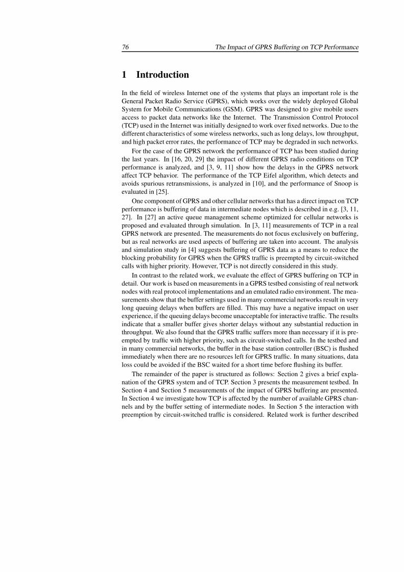
76 The Impact of GPRS Buffering on TCP Performance
1 Introduction
In the field of wireless Internet one of the systems that plays an important role is theGeneral Packet Radio Service (GPRS), which works over the widely deployed GlobalSystem for Mobile Communications (GSM). GPRS was designed to give mobile usersaccess to packet data networks like the Internet. The Transmission Control Protocol(TCP) used in the Internet was initially designed to work over fixed networks. Due to thedifferent characteristics of some wireless networks, such as long delays, low throughput,and high packet error rates, the performance of TCP may be degraded in such networks.
For the case of the GPRS network the performance of TCP has been studied duringthe last years. In [16, 20, 29] the impact of different GPRS radio conditions on TCPperformance is analyzed, and [3, 9, 11] show how the delays in the GPRS networkaffect TCP behavior. The performance of the TCP Eifel algorithm, which detects andavoids spurious retransmissions, is analyzed in [10], and the performance of Snoop isevaluated in [25].
One component of GPRS and other cellular networks that has a direct impact on TCPperformance is buffering of data in intermediate nodes which is described in e.g. [3, 11,27]. In [27] an active queue management scheme optimized for cellular networks isproposed and evaluated through simulation. In [3, 11] measurements of TCP in a realGPRS network are presented. The measurements do not focus exclusively on buffering,but as real networks are used aspects of buffering are taken into account. The analysisand simulation study in [4] suggests buffering of GPRS data as a means to reduce theblocking probability for GPRS when the GPRS traffic is preempted by circuit-switchedcalls with higher priority. However, TCP is not directly considered in this study.
In contrast to the related work, we evaluate the effect of GPRS buffering on TCP indetail. Our work is based on measurements in a GPRS testbed consisting of real networknodes with real protocol implementations and an emulated radio environment. The mea-surements show that the buffer settings used in many commercial networks result in verylong queuing delays when buffers are filled. This may have a negative impact on userexperience, if the queuing delays become unacceptable for interactive traffic. The resultsindicate that a smaller buffer gives shorter delays without any substantial reduction inthroughput. We also found that the GPRS traffic suffers more than necessary if it is pre-empted by traffic with higher priority, such as circuit-switched calls. In the testbed andin many commercial networks, the buffer in the base station controller (BSC) is flushedimmediately when there are no resources left for GPRS traffic. In many situations, dataloss could be avoided if the BSC waited for a short time before flushing its buffer.
The remainder of the paper is structured as follows: Section 2 gives a brief expla-nation of the GPRS system and of TCP. Section 3 presents the measurement testbed. InSection 4 and Section 5 measurements of the impact of GPRS buffering are presented.In Section 4 we investigate how TCP is affected by the number of available GPRS chan-nels and by the buffer setting of intermediate nodes. In Section 5 the interaction withpreemption by circuit-switched traffic is considered. Related work is further described
2. Background 77
NetworkService
NetworkService
Um Gb Gn GiMS
GTP
IP/X.25
IP
L2
L1
GGSN
UDP/TCP
Relay
LLC
BSSGP
L1bis
SNDCP GTP
IP
L2
L1
SGSN
UDP/TCPLLC
GSM RF
Application
IP/X.25
SNDCP
BSS
Relay
GSM RF L1bis
BSSGPRLC RLC
MAC MAC
Figure 1: The GPRS transmission plane, taken from [8]
and discussed in Section 6. Finally, Section 7 summarizes the conclusions and outlinesour plans for future work.
2 BackgroundIn this section some background on GPRS and TCP is provided. The main purpose is toprovide the information required for the rest of the paper, not to give a complete pictureof either GPRS or TCP.
2.1 Overview of GPRS
GPRS [8, 2] is a packet-oriented extension to GSM that supplies higher data rates andsharing of radio resources. The GPRS system makes changes to the GSM system in thefixed network and in the radio interface. In the fixed network the GPRS system adds twonew nodes: the Gateway GPRS Support Node (GGSN) and the Serving GPRS SupportNode (SGSN). In the radio interface Packet Data Channels (PDCHs) are introduced forGPRS data and signaling traffic. A PDCH corresponds to a GSM timeslot which iseither dedicated for GPRS traffic or dynamically allocated when a PDCH is required.The PDCHs that are available in a cell can be shared between many mobile stations,since GPRS resources are only assigned to a mobile station when it has data to transmit.A single mobile station may also use more than one PDCH, depending on the type ofterminal.
Figure 1 shows the main nodes and the protocols that take part in a data transmissionthrough the GPRS network [8]. The GGSN connects the GPRS network to other packetdata networks, such as the Internet, over the Gi interface. User data from an externalpacket network is transmitted from the GGSN over the Gn interface to the SGSN, and
78 The Impact of GPRS Buffering on TCP Performance
then the SGSN routes packets over the Gb interface to the right Base Station Subsystem(BSS).
The GGSN and SGSN nodes exchange IP datagrams carrying user data and signal-ing messages over the GPRS Tunneling Protocol (GTP) which in turn runs on top ofa TCP/IP protocol stack. The SGSN manages logical links with the mobile terminalsin its routing area using the Logical Link Control (LLC) protocol. The SubnetworkDependent Convergence Protocol (SNDCP) multiplexes packets from possibly differentnetwork layer protocols, such as IP and X.25, and segments and reassembles networkprotocol data units (PDUs) if necessary. Optionally, SNDCP also performs header anddata compression. Between the SGSN and the BSS, the Base Station Subsystem GPRSProtocol (BSSGP) and the Network Service protocol operate over Frame Relay. BSSGPflow controls data in the down link between the SGSN and the BSS. This is furtherdescribed in Section 3.
In the radio interface (Um) the GPRS system adds new coding schemes and retrans-mission protocols. Four coding schemes are standardized for transmitting data blocks(CS1-CS4) [6]. Coding scheme 1 (CS-1) is the most robust code and it is used for sig-naling, whereas any of the four coding schemes can be used for data transmission. In theradio interface LLC and Radio Link Control (RLC) protocols are defined to work in twomodes: unacknowledged and acknowledged mode. In both protocols the acknowledgedmode provides a more reliable transmission of data frames and blocks.
2.2 Overview of TCP
The TCP protocol provides reliable data transport [24]. TCP performs congestion andflow control. Congestion control depends on the congestion window (cwnd) variable [1]which is used as an estimate of the instantaneous capacity of the network. The cwndlimits the amount of data the TCP sender can inject into the network. The sender per-forms flow control based on feedback from the receiver. The receiver sets the advertisedreceiver window field in the acknowledgments to inform the sender about the availablespace in the receiver buffer. At any moment, the outstanding data, i.e., the number ofbytes whose acknowledgment has still not been received by the TCP sender, is limitedby the minimum of the cwnd and the advertised receiver window.
The TCP sender has two ways of detecting that a packet is missing and needs to beretransmitted: timer-driven and data-driven retransmission. The TCP sender performsa timer-driven retransmission by calculating the round trip time (RTT) of the TCP seg-ments. TCP manages a retransmission timer based on the RTT measurements. The timeris set when a segment is transmitted. If no acknowledgment is received within a timeout period, then data is considered lost. The missing data is retransmitted and the TCPsender enters a slow start phase. In the slow start phase the cwnd is set to one packet andincreased with one packet with each ACK the TCP sender receives. When a slow startthreshold (ssthresh) value is reached, the congestion avoidance algorithm is used. In thecongestion avoidance phase one new segment is added per RTT.
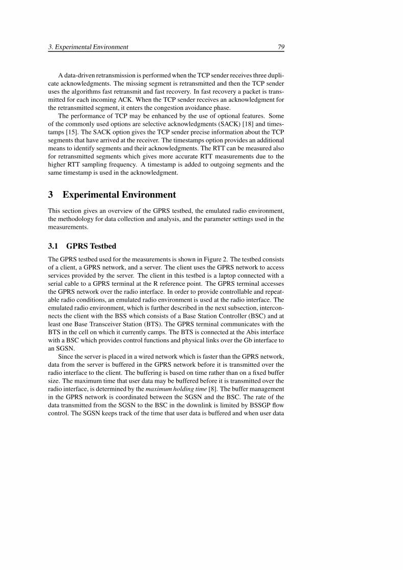
3. Experimental Environment 79
A data-driven retransmission is performed when the TCP sender receives three dupli-cate acknowledgments. The missing segment is retransmitted and then the TCP senderuses the algorithms fast retransmit and fast recovery. In fast recovery a packet is trans-mitted for each incoming ACK. When the TCP sender receives an acknowledgment forthe retransmitted segment, it enters the congestion avoidance phase.
The performance of TCP may be enhanced by the use of optional features. Someof the commonly used options are selective acknowledgments (SACK) [18] and times-tamps [15]. The SACK option gives the TCP sender precise information about the TCPsegments that have arrived at the receiver. The timestamps option provides an additionalmeans to identify segments and their acknowledgments. The RTT can be measured alsofor retransmitted segments which gives more accurate RTT measurements due to thehigher RTT sampling frequency. A timestamp is added to outgoing segments and thesame timestamp is used in the acknowledgment.
3 Experimental EnvironmentThis section gives an overview of the GPRS testbed, the emulated radio environment,the methodology for data collection and analysis, and the parameter settings used in themeasurements.
3.1 GPRS TestbedThe GPRS testbed used for the measurements is shown in Figure 2. The testbed consistsof a client, a GPRS network, and a server. The client uses the GPRS network to accessservices provided by the server. The client in this testbed is a laptop connected with aserial cable to a GPRS terminal at the R reference point. The GPRS terminal accessesthe GPRS network over the radio interface. In order to provide controllable and repeat-able radio conditions, an emulated radio environment is used at the radio interface. Theemulated radio environment, which is further described in the next subsection, intercon-nects the client with the BSS which consists of a Base Station Controller (BSC) and atleast one Base Transceiver Station (BTS). The GPRS terminal communicates with theBTS in the cell on which it currently camps. The BTS is connected at the Abis interfacewith a BSC which provides control functions and physical links over the Gb interface toan SGSN.
Since the server is placed in a wired network which is faster than the GPRS network,data from the server is buffered in the GPRS network before it is transmitted over theradio interface to the client. The buffering is based on time rather than on a fixed buffersize. The maximum time that user data may be buffered before it is transmitted over theradio interface, is determined by the maximum holding time [8]. The buffer managementin the GPRS network is coordinated between the SGSN and the BSC. The rate of thedata transmitted from the SGSN to the BSC in the downlink is limited by BSSGP flowcontrol. The SGSN keeps track of the time that user data is buffered and when user data
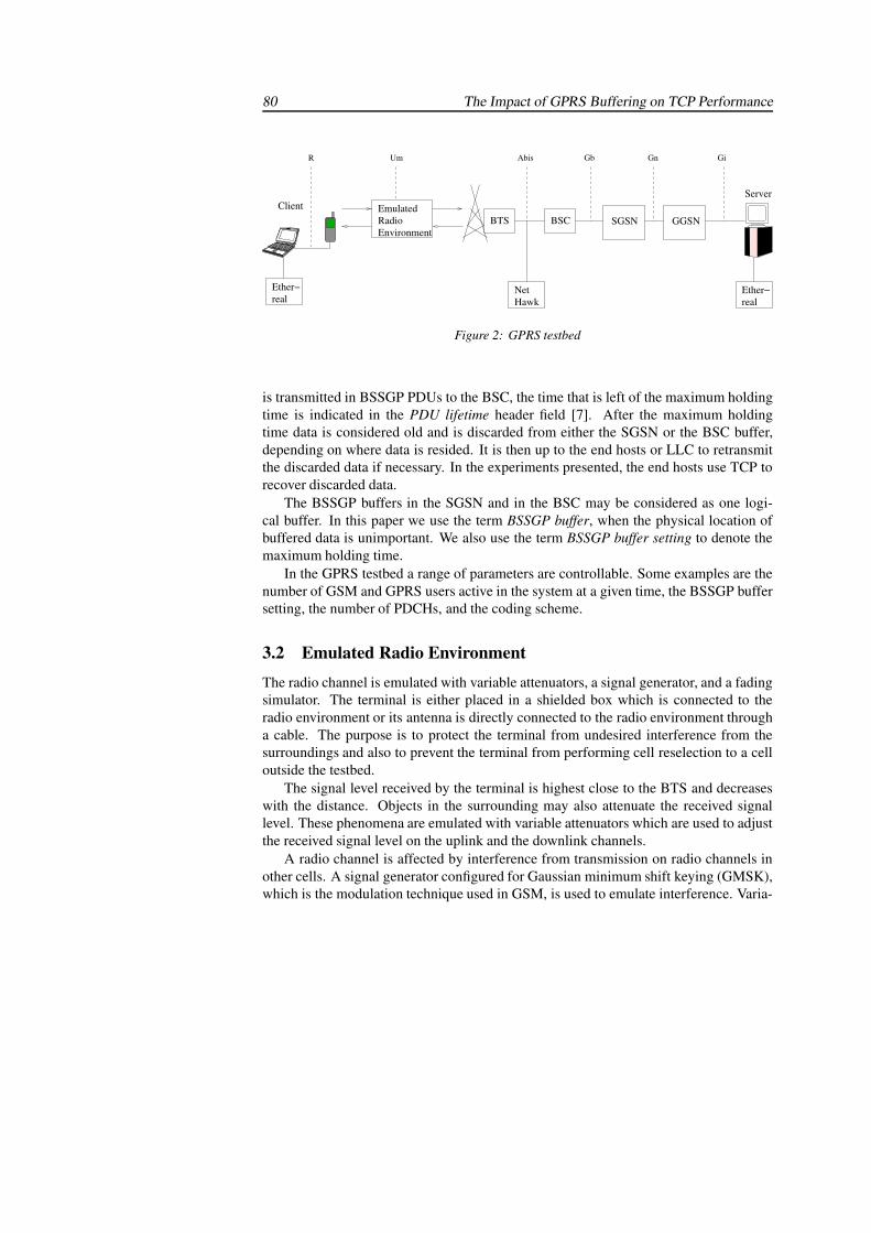
80 The Impact of GPRS Buffering on TCP Performance
realEther−
realEther− Net
Hawk
BSC
ServerEmulatedRadioEnvironment
BTS SGSN GGSN
R Um Abis Gb Gn Gi
Client
Figure 2: GPRS testbed
is transmitted in BSSGP PDUs to the BSC, the time that is left of the maximum holdingtime is indicated in the PDU lifetime header field [7]. After the maximum holdingtime data is considered old and is discarded from either the SGSN or the BSC buffer,depending on where data is resided. It is then up to the end hosts or LLC to retransmitthe discarded data if necessary. In the experiments presented, the end hosts use TCP torecover discarded data.
The BSSGP buffers in the SGSN and in the BSC may be considered as one logi-cal buffer. In this paper we use the term BSSGP buffer, when the physical location ofbuffered data is unimportant. We also use the term BSSGP buffer setting to denote themaximum holding time.
In the GPRS testbed a range of parameters are controllable. Some examples are thenumber of GSM and GPRS users active in the system at a given time, the BSSGP buffersetting, the number of PDCHs, and the coding scheme.
3.2 Emulated Radio Environment
The radio channel is emulated with variable attenuators, a signal generator, and a fadingsimulator. The terminal is either placed in a shielded box which is connected to theradio environment or its antenna is directly connected to the radio environment througha cable. The purpose is to protect the terminal from undesired interference from thesurroundings and also to prevent the terminal from performing cell reselection to a celloutside the testbed.
The signal level received by the terminal is highest close to the BTS and decreaseswith the distance. Objects in the surrounding may also attenuate the received signallevel. These phenomena are emulated with variable attenuators which are used to adjustthe received signal level on the uplink and the downlink channels.
A radio channel is affected by interference from transmission on radio channels inother cells. A signal generator configured for Gaussian minimum shift keying (GMSK),which is the modulation technique used in GSM, is used to emulate interference. Varia-
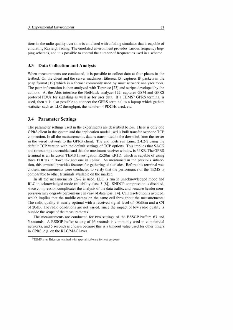
3. Experimental Environment 81
tions in the radio quality over time is emulated with a fading simulator that is capable ofemulating Rayleigh fading. The emulated environment provides various frequency hop-ping schemes, and it is possible to control the number of frequencies used in a scheme.
3.3 Data Collection and Analysis
When measurements are conducted, it is possible to collect data at four places in thetestbed. On the client and the server machines, Ethereal [5] captures IP packets in thepcap format [19] which is a format commonly used by most network analyzer tools.The pcap information is then analyzed with Tcptrace [23] and scripts developed by theauthors. At the Abis interface the NetHawk analyzer [22] captures GSM and GPRSprotocol PDUs for signaling as well as for user data. If a TEMS3 GPRS terminal isused, then it is also possible to connect the GPRS terminal to a laptop which gathersstatistics such as LLC throughput, the number of PDCHs used, etc.
3.4 Parameter Settings
The parameter settings used in the experiments are described below. There is only oneGPRS client in the system and the application model used is bulk transfer over one TCPconnection. In all the measurements, data is transmitted in the downlink from the serverin the wired network to the GPRS client. The end hosts run Linux 2.4.2-2 using thedefault TCP version with the default settings of TCP options. This implies that SACKand timestamps are enabled and that the maximum receiver window is 64KB. The GPRSterminal is an Ericsson TEMS Investigation R520m v.R1D, which is capable of usingthree PDCHs in downlink and one in uplink. As mentioned in the previous subsec-tion, this terminal provides features for gathering of statistics. Before this terminal waschosen, measurements were conducted to verify that the performance of the TEMS iscomparable to other terminals available on the market.
In all the measurements CS-2 is used, LLC is run in unacknowledged mode andRLC in acknowledged mode (reliability class 3 [8]). SNDCP compression is disabled,since compression complicates the analysis of the data traffic, and because header com-pression may degrade performance in case of data loss [14]. Cell reselection is avoided,which implies that the mobile camps on the same cell throughout the measurements.The radio quality is nearly optimal with a received signal level of -80dBm and a C/Iof 20dB. The radio conditions are not varied, since the impact of low radio quality isoutside the scope of the measurements.
The measurements are conducted for two settings of the BSSGP buffer: 63 and5 seconds. A BSSGP buffer setting of 63 seconds is commonly used in commercialnetworks, and 5 seconds is chosen because this is a timeout value used for other timersin GPRS, e.g. on the RLC/MAC layer.
3TEMS is an Ericsson terminal with special software for test purposes.
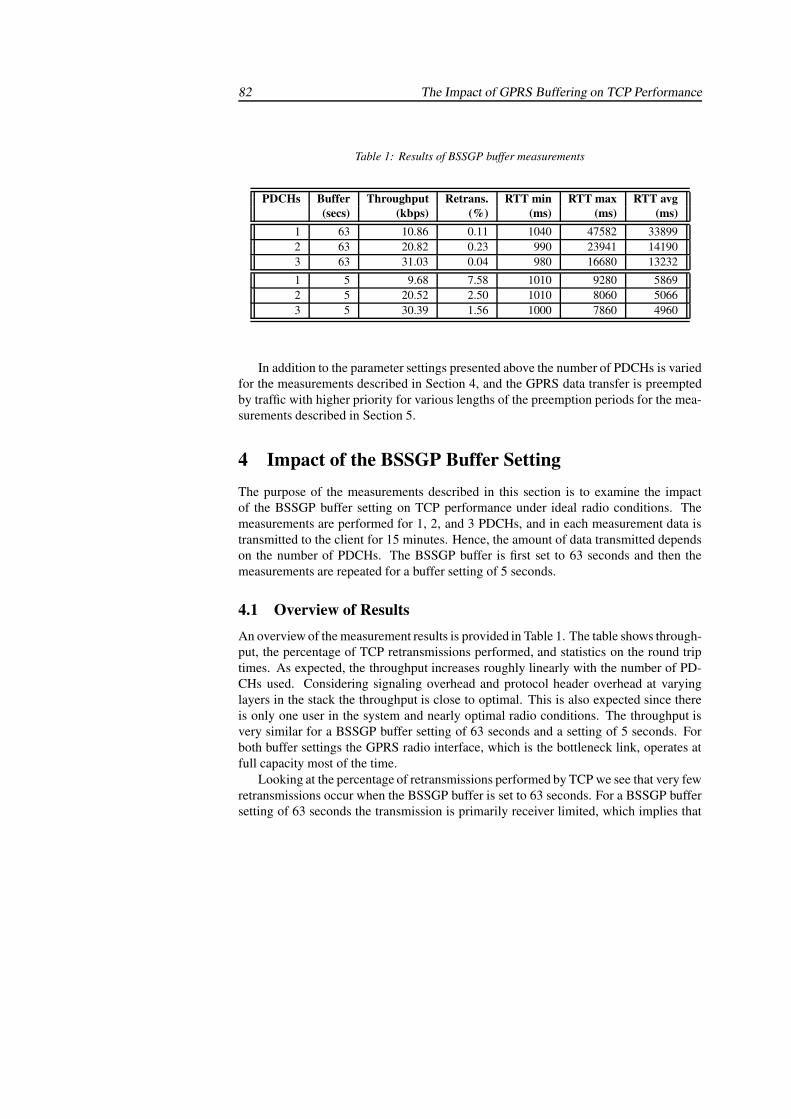
82 The Impact of GPRS Buffering on TCP Performance
Table 1: Results of BSSGP buffer measurements
PDCHs Buffer Throughput Retrans. RTT min RTT max RTT avg(secs) (kbps) (%) (ms) (ms) (ms)
1 63 10.86 0.11 1040 47582 338992 63 20.82 0.23 990 23941 141903 63 31.03 0.04 980 16680 13232
1 5 9.68 7.58 1010 9280 58692 5 20.52 2.50 1010 8060 50663 5 30.39 1.56 1000 7860 4960
In addition to the parameter settings presented above the number of PDCHs is variedfor the measurements described in Section 4, and the GPRS data transfer is preemptedby traffic with higher priority for various lengths of the preemption periods for the mea-surements described in Section 5.
4 Impact of the BSSGP Buffer SettingThe purpose of the measurements described in this section is to examine the impactof the BSSGP buffer setting on TCP performance under ideal radio conditions. Themeasurements are performed for 1, 2, and 3 PDCHs, and in each measurement data istransmitted to the client for 15 minutes. Hence, the amount of data transmitted dependson the number of PDCHs. The BSSGP buffer is first set to 63 seconds and then themeasurements are repeated for a buffer setting of 5 seconds.
4.1 Overview of ResultsAn overview of the measurement results is provided in Table 1. The table shows through-put, the percentage of TCP retransmissions performed, and statistics on the round triptimes. As expected, the throughput increases roughly linearly with the number of PD-CHs used. Considering signaling overhead and protocol header overhead at varyinglayers in the stack the throughput is close to optimal. This is also expected since thereis only one user in the system and nearly optimal radio conditions. The throughput isvery similar for a BSSGP buffer setting of 63 seconds and a setting of 5 seconds. Forboth buffer settings the GPRS radio interface, which is the bottleneck link, operates atfull capacity most of the time.
Looking at the percentage of retransmissions performed by TCP we see that very fewretransmissions occur when the BSSGP buffer is set to 63 seconds. For a BSSGP buffersetting of 63 seconds the transmission is primarily receiver limited, which implies that
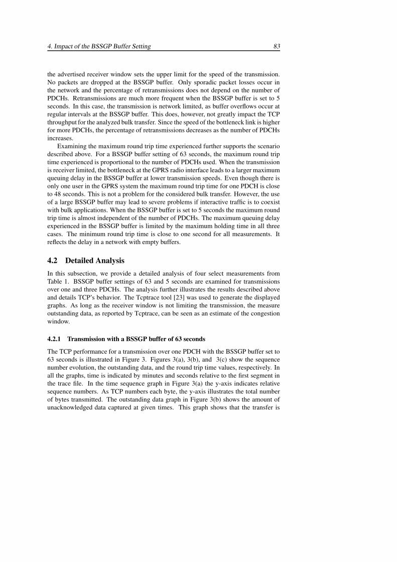
4. Impact of the BSSGP Buffer Setting 83
the advertised receiver window sets the upper limit for the speed of the transmission.No packets are dropped at the BSSGP buffer. Only sporadic packet losses occur inthe network and the percentage of retransmissions does not depend on the number ofPDCHs. Retransmissions are much more frequent when the BSSGP buffer is set to 5seconds. In this case, the transmission is network limited, as buffer overflows occur atregular intervals at the BSSGP buffer. This does, however, not greatly impact the TCPthroughput for the analyzed bulk transfer. Since the speed of the bottleneck link is higherfor more PDCHs, the percentage of retransmissions decreases as the number of PDCHsincreases.
Examining the maximum round trip time experienced further supports the scenariodescribed above. For a BSSGP buffer setting of 63 seconds, the maximum round triptime experienced is proportional to the number of PDCHs used. When the transmissionis receiver limited, the bottleneck at the GPRS radio interface leads to a larger maximumqueuing delay in the BSSGP buffer at lower transmission speeds. Even though there isonly one user in the GPRS system the maximum round trip time for one PDCH is closeto 48 seconds. This is not a problem for the considered bulk transfer. However, the useof a large BSSGP buffer may lead to severe problems if interactive traffic is to coexistwith bulk applications. When the BSSGP buffer is set to 5 seconds the maximum roundtrip time is almost independent of the number of PDCHs. The maximum queuing delayexperienced in the BSSGP buffer is limited by the maximum holding time in all threecases. The minimum round trip time is close to one second for all measurements. Itreflects the delay in a network with empty buffers.
4.2 Detailed AnalysisIn this subsection, we provide a detailed analysis of four select measurements fromTable 1. BSSGP buffer settings of 63 and 5 seconds are examined for transmissionsover one and three PDCHs. The analysis further illustrates the results described aboveand details TCP’s behavior. The Tcptrace tool [23] was used to generate the displayedgraphs. As long as the receiver window is not limiting the transmission, the measureoutstanding data, as reported by Tcptrace, can be seen as an estimate of the congestionwindow.
4.2.1 Transmission with a BSSGP buffer of 63 seconds
The TCP performance for a transmission over one PDCH with the BSSGP buffer set to63 seconds is illustrated in Figure 3. Figures 3(a), 3(b), and 3(c) show the sequencenumber evolution, the outstanding data, and the round trip time values, respectively. Inall the graphs, time is indicated by minutes and seconds relative to the first segment inthe trace file. In the time sequence graph in Figure 3(a) the y-axis indicates relativesequence numbers. As TCP numbers each byte, the y-axis illustrates the total numberof bytes transmitted. The outstanding data graph in Figure 3(b) shows the amount ofunacknowledged data captured at given times. This graph shows that the transfer is
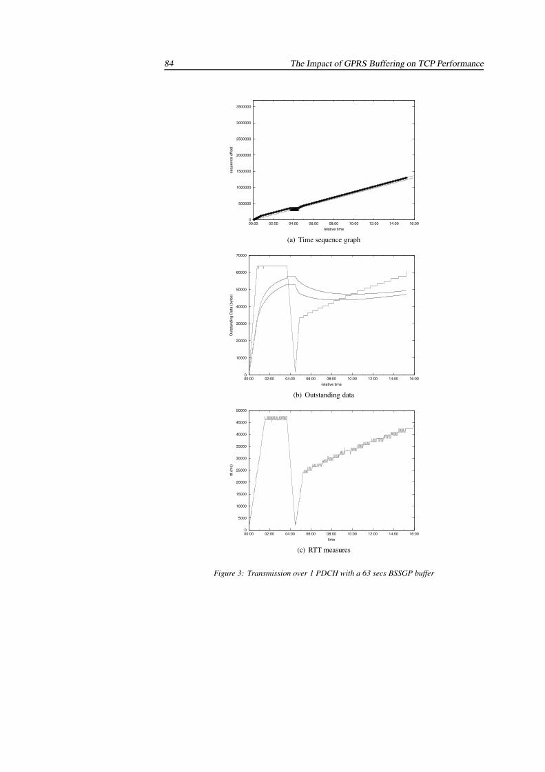
84 The Impact of GPRS Buffering on TCP Performance
0
500000
1000000
1500000
2000000
2500000
3000000
3500000
00:00 02:00 04:00 06:00 08:00 10:00 12:00 14:00 16:00
sequ
ence
offs
etrelative time
SYN
SS3SRSSSSSSSSSSSSSSSSSSSSSSSSSSSSSSSSSSSSSSSS
FIN
(a) Time sequence graph
0
10000
20000
30000
40000
50000
60000
70000
00:00 02:00 04:00 06:00 08:00 10:00 12:00 14:00 16:00
Out
stan
ding
Dat
a (b
ytes
)
relative time
(b) Outstanding data
0
5000
10000
15000
20000
25000
30000
35000
40000
45000
50000
00:00 02:00 04:00 06:00 08:00 10:00 12:00 14:00 16:00
rtt (m
s)
time
(c) RTT measures
Figure 3: Transmission over 1 PDCH with a 63 secs BSSGP buffer
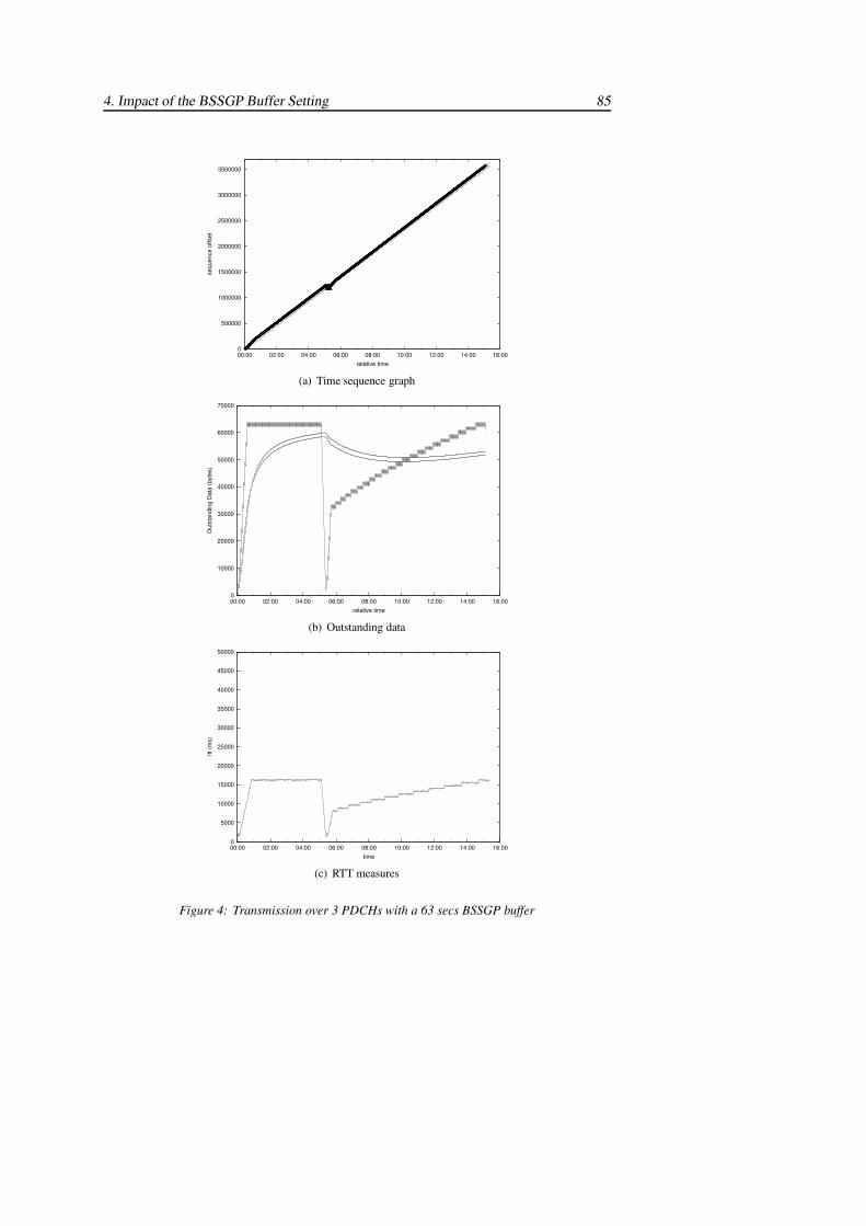
4. Impact of the BSSGP Buffer Setting 85
0
500000
1000000
1500000
2000000
2500000
3000000
3500000
00:00 02:00 04:00 06:00 08:00 10:00 12:00 14:00 16:00
sequ
ence
offs
et
relative time
SYN
SSRS3SSSSSSSSSSSSSSSSSSS
FIN
(a) Time sequence graph
0
10000
20000
30000
40000
50000
60000
70000
00:00 02:00 04:00 06:00 08:00 10:00 12:00 14:00 16:00
Out
stan
ding
Dat
a (b
ytes
)
relative time
(b) Outstanding data
0
5000
10000
15000
20000
25000
30000
35000
40000
45000
50000
00:00 02:00 04:00 06:00 08:00 10:00 12:00 14:00 16:00
rtt (m
s)
time
(c) RTT measures
Figure 4: Transmission over 3 PDCHs with a 63 secs BSSGP buffer
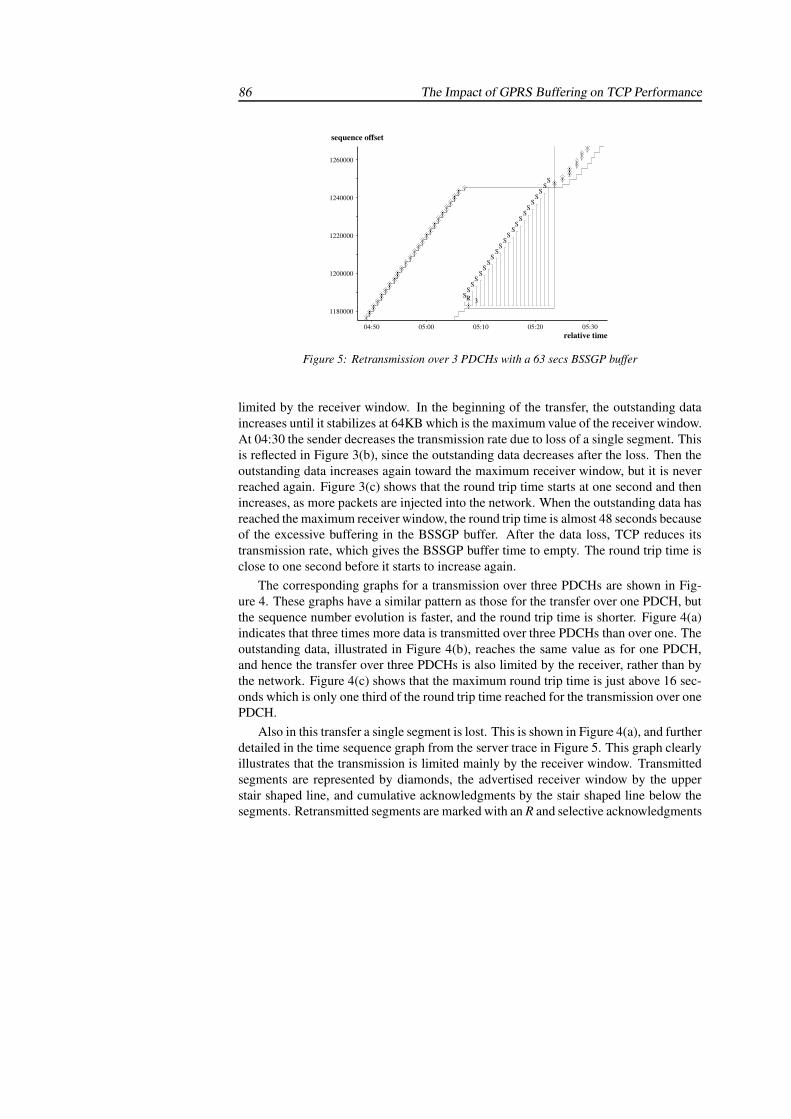
86 The Impact of GPRS Buffering on TCP Performance
1260000
1240000
1220000
1200000
1180000
05:30 05:20 05:10 05:00 04:50
sequence offset
relative time
���������������SS
SS
SS
SS
SS
SS
SS
SS
SS
S
3
S
�RS
�
S
������������������������������������������������
Figure 5: Retransmission over 3 PDCHs with a 63 secs BSSGP buffer
limited by the receiver window. In the beginning of the transfer, the outstanding dataincreases until it stabilizes at 64KB which is the maximum value of the receiver window.At 04:30 the sender decreases the transmission rate due to loss of a single segment. Thisis reflected in Figure 3(b), since the outstanding data decreases after the loss. Then theoutstanding data increases again toward the maximum receiver window, but it is neverreached again. Figure 3(c) shows that the round trip time starts at one second and thenincreases, as more packets are injected into the network. When the outstanding data hasreached the maximum receiver window, the round trip time is almost 48 seconds becauseof the excessive buffering in the BSSGP buffer. After the data loss, TCP reduces itstransmission rate, which gives the BSSGP buffer time to empty. The round trip time isclose to one second before it starts to increase again.
The corresponding graphs for a transmission over three PDCHs are shown in Fig-ure 4. These graphs have a similar pattern as those for the transfer over one PDCH, butthe sequence number evolution is faster, and the round trip time is shorter. Figure 4(a)indicates that three times more data is transmitted over three PDCHs than over one. Theoutstanding data, illustrated in Figure 4(b), reaches the same value as for one PDCH,and hence the transfer over three PDCHs is also limited by the receiver, rather than bythe network. Figure 4(c) shows that the maximum round trip time is just above 16 sec-onds which is only one third of the round trip time reached for the transmission over onePDCH.
Also in this transfer a single segment is lost. This is shown in Figure 4(a), and furtherdetailed in the time sequence graph from the server trace in Figure 5. This graph clearlyillustrates that the transmission is limited mainly by the receiver window. Transmittedsegments are represented by diamonds, the advertised receiver window by the upperstair shaped line, and cumulative acknowledgments by the stair shaped line below thesegments. Retransmitted segments are marked with an R and selective acknowledgments
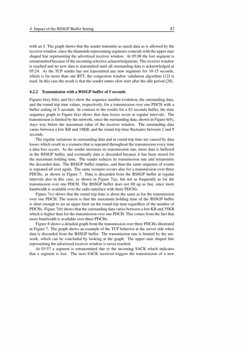
4. Impact of the BSSGP Buffer Setting 87
with an S. The graph shows that the sender transmits as much data as is allowed by thereceiver window, since the diamonds representing segments coincide with the upper stairshaped line representing the advertised receiver window. At 05:08 the lost segment isretransmitted because of the incoming selective acknowledgments. The receiver windowis reached and no new data is transmitted until all outstanding data is acknowledged at05:24. As the TCP sender has not transmitted any new segments for 10-15 seconds,which is far more than one RTT, the congestion window validation algorithm [12] isused. In this case the result is that the sender enters slow start after the idle period [28].
4.2.2 Transmission with a BSSGP buffer of 5 seconds
Figures 6(a), 6(b), and 6(c) show the sequence number evolution, the outstanding data,and the round trip time values, respectively, for a transmission over one PDCH with abuffer setting of 5 seconds. In contrast to the results for a 63 seconds buffer, the timesequence graph in Figure 6(a) shows that data losses occur at regular intervals. Thetransmission is limited by the network, since the outstanding data, shown in Figure 6(b),stays way below the maximum value of the receiver window. The outstanding datavaries between a few KB and 18KB, and the round trip time fluctuates between 2 and 9seconds.
The regular variations in outstanding data and in round trip time are caused by datalosses which result in a scenario that is repeated throughout the transmission every timea data loss occurs. As the sender increases its transmission rate, more data is bufferedin the BSSGP buffer, and eventually data is discarded because it has been stored forthe maximum holding time. The sender reduces its transmission rate and retransmitsthe discarded data. The BSSGP buffer empties, and then the same sequence of eventsis repeated all over again. The same scenario occurs also for a transmission over threePDCHs, as shown in Figure 7. Data is discarded from the BSSGP buffer at regularintervals also in this case, as shown in Figure 7(a), but not as frequently as for thetransmission over one PDCH. The BSSGP buffer does not fill up as fast, since morebandwidth is available over the radio interface with three PDCHs.
Figure 7(c) shows that the round trip time is about the same as for the transmissionover one PDCH. The reason is that the maximum holding time of the BSSGP bufferis short enough to set an upper limit on the round trip time regardless of the number ofPDCHs. Figure 7(b) shows that the outstanding data varies between a few KB and 35KBwhich is higher than for the transmission over one PDCH. This comes from the fact thatmore bandwidth is available over three PDCHs.
Figure 8 shows a detailed graph from the transmission over three PDCHs illustratedin Figure 7. The graph shows an example of the TCP behavior at the server side whendata is discarded from the BSSGP buffer. The transmission rate is limited by the net-work, which can be concluded by looking at the graph. The upper stair shaped linerepresenting the advertised receiver window is never reached.
At 03:57 a segment is retransmitted due to the incoming SACK which indicatesthat a segment is lost. The next SACK received triggers the transmission of a new
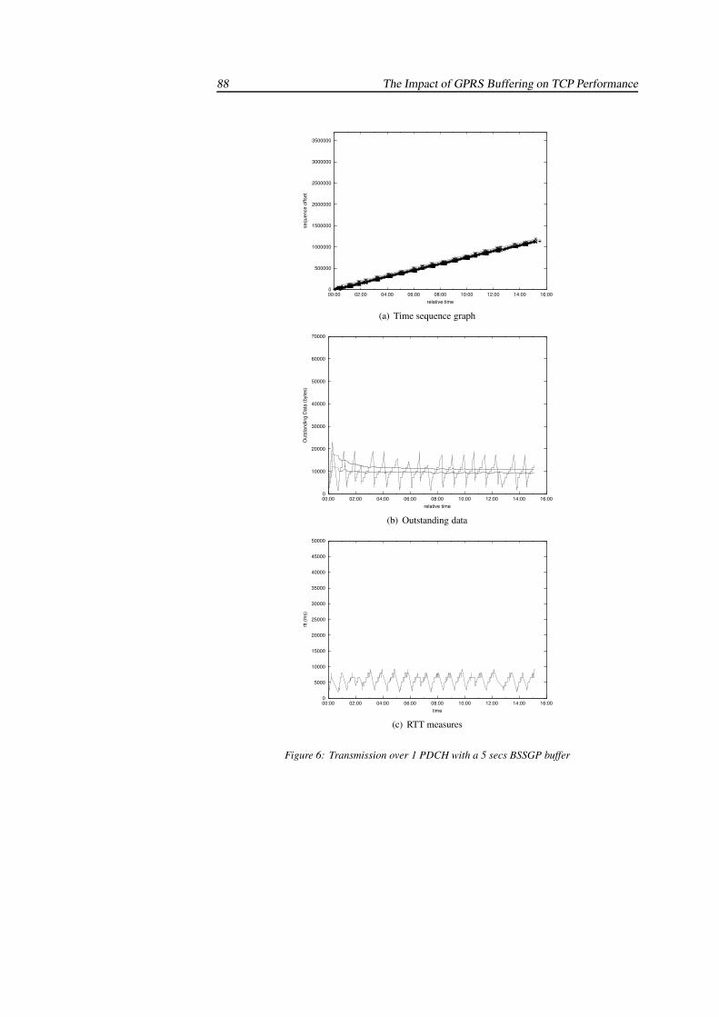
88 The Impact of GPRS Buffering on TCP Performance
0
500000
1000000
1500000
2000000
2500000
3000000
3500000
00:00 02:00 04:00 06:00 08:00 10:00 12:00 14:00 16:00
sequ
ence
offs
etrelative time
121231231231231231231212 1212121212121212
12121212 1212121212312121212312312312
12121212312312 12121212312 1212 12121231231231212121212123123121212
1212121212 1212
SYNSSR3SRSRSRSRSSRSSRSSRSRSRSR SS3SRSSSSSRSSSSSRS SS3SRSSSSSS SRS3SSSS SS3SRSSSSSSRSSS SS3SRSSSSSSSRS3SRSSSSR3SSRSSSSRSSR
SSR3SSRSRSRSSS SS3SRSSSSSS SSR3SSRSSRSSR SS3SRSSSSRSRSSRS SS3SRSSSSSSSRS3S SS3SRSSSSRSSRSRS SS3SRSSSSSS SSR3SSRSSSSSRSRSSS3SRSSSRSRSSSSSS3SRSSRSR
SS3SRSSSSRSSRSSR SS3SRSSSSSSSRS3SFINSS3SRSRR FIN
(a) Time sequence graph
0
10000
20000
30000
40000
50000
60000
70000
00:00 02:00 04:00 06:00 08:00 10:00 12:00 14:00 16:00
Out
stan
ding
Dat
a (b
ytes
)
relative time
(b) Outstanding data
0
5000
10000
15000
20000
25000
30000
35000
40000
45000
50000
00:00 02:00 04:00 06:00 08:00 10:00 12:00 14:00 16:00
rtt (m
s)
time
(c) RTT measures
Figure 6: Transmission over 1 PDCH with a 5 secs BSSGP buffer
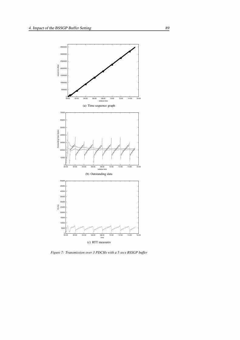
4. Impact of the BSSGP Buffer Setting 89
0
500000
1000000
1500000
2000000
2500000
3000000
3500000
00:00 02:00 04:00 06:00 08:00 10:00 12:00 14:00 16:00
sequ
ence
offs
et
relative time
121212123123123123123123123123121212
12121212
121212312312312312
121231231231212312
1212121212
12121212123123123123
12121212
12121231231231231231212
SYNSSRSR3SSRSRSRSRSRSRSRSRSRSRSRSRSRSR
SSRS3SSSSRSSSSS
SRS3SRSRSRSSSS
SRS3SSSRSRSSSSRSS
SSRS3SSSRSSSSS
SSRSR3SSSSRSSSS
SSRS3SSSSRSSSSS
SRSR3SSRSRSSRSSS
FIN
(a) Time sequence graph
0
10000
20000
30000
40000
50000
60000
70000
00:00 02:00 04:00 06:00 08:00 10:00 12:00 14:00 16:00
Out
stan
ding
Dat
a (b
ytes
)
relative time
(b) Outstanding data
0
5000
10000
15000
20000
25000
30000
35000
40000
45000
50000
00:00 02:00 04:00 06:00 08:00 10:00 12:00 14:00 16:00
rtt (m
s)
time
(c) RTT measures
Figure 7: Transmission over 3 PDCHs with a 5 secs BSSGP buffer
90 The Impact of GPRS Buffering on TCP Performance
920000
900000
880000
860000
04:05 04:00 03:55 03:50
sequence offset
relative time
������������S�S
2
1
�S
3
2
1
�S
3
2
1
�RS
3
2
1
�RS
3
2
1
�RS
2
1
3
�
S
21
�RS
��������������������������
Figure 8: Retransmission over 3 PDCHs with a 5 secs BSSGP buffer
segment. Then three segments are retransmitted due to the incoming SACKs. In totalfour segments are discarded, since they could not be transmitted over the radio interfacebefore their maximum holding times were reached.
4.3 Discussion of Results
The results depend both on the buffer setting and on the number of PDCHs used. TCPthroughput remains almost the same for both buffer settings, but it increases with anincreasing number of PDCHs. The round trip time is strongly related to the buffer set-ting, and the 63 seconds buffer results in an extremely long round trip time, almost 48seconds for one PDCH in this case. The transmission is receiver limited and up to 64KBmay be buffered in the GPRS network. The 5 seconds buffer gives a shorter round triptime, but at the cost of data loss due to BSSGP buffer overflows. The transmission isnetwork limited, since data is discarded from the BSSGP buffer. However, the retrans-mitted TCP segments do not waste any radio resources, since the lost data is discardedfrom the BSSGP buffer before it is transmitted over the radio link.
The long round trip time caused by a BSSGP buffer setting of 63 seconds is not aproblem for the throughput of the considered bulk transfer. From a user’s perspective,on the other hand, a long round trip time may be undesirable. If a user chooses tointerrupt a transmission, for example by pressing the stop button in a web browser, thendata buffered in the BSSGP buffer must first be transmitted before the user can receiveany new data. Excessive buffering and long round trip times may also cause problemsfor interactive traffic if data is transmitted over both bulk and interactive connectionssimultaneously. The interactive traffic may also suffer in case of data loss, since TCPreacts slowly to errors when the queuing delay in the BSSGP buffer results in a longround trip time.
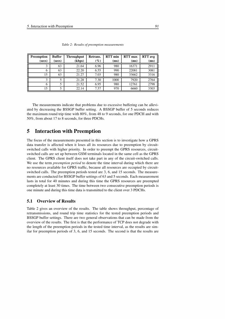
5. Interaction with Preemption 91
Table 2: Results of preemption measurements
Preemption Buffer Throughput Retrans. RTT min RTT max RTT avg(secs) (secs) (kbps) (%) (ms) (ms) (ms)
3 63 21.64 6.96 980 16371 29116 63 22.20 6.55 990 22081 3081
15 63 21.27 7.03 980 33662 3316
3 5 21.28 7.30 1000 7920 27646 5 21.52 6.95 980 12761 2798
15 5 22.14 7.57 970 6660 3303
The measurements indicate that problems due to excessive buffering can be allevi-ated by decreasing the BSSGP buffer setting. A BSSGP buffer of 5 seconds reducesthe maximum round trip time with 80%, from 48 to 9 seconds, for one PDCH and with50%, from about 17 to 8 seconds, for three PDCHs.
5 Interaction with PreemptionThe focus of the measurements presented in this section is to investigate how a GPRSdata transfer is affected when it loses all its resources due to preemption by circuit-switched calls with higher priority. In order to preempt the GPRS resources, circuit-switched calls are set up between GSM terminals located in the same cell as the GPRSclient. The GPRS client itself does not take part in any of the circuit-switched calls.We use the term preemption period to denote the time interval during which there areno resources available for GPRS traffic, because all resources are occupied by circuit-switched calls. The preemption periods tested are 3, 6, and 15 seconds. The measure-ments are conducted for BSSGP buffer settings of 63 and 5 seconds. Each measurementlasts in total for 40 minutes and during this time the GPRS resources are preemptedcompletely at least 30 times. The time between two consecutive preemption periods isone minute and during this time data is transmitted to the client over 3 PDCHs.
5.1 Overview of ResultsTable 2 gives an overview of the results. The table shows throughput, percentage ofretransmissions, and round trip time statistics for the tested preemption periods andBSSGP buffer settings. There are two general observations that can be made from theoverview of the results. The first is that the performance of TCP does not degrade withthe length of the preemption periods in the tested time interval, as the results are sim-ilar for preemption periods of 3, 6, and 15 seconds. The second is that the results are
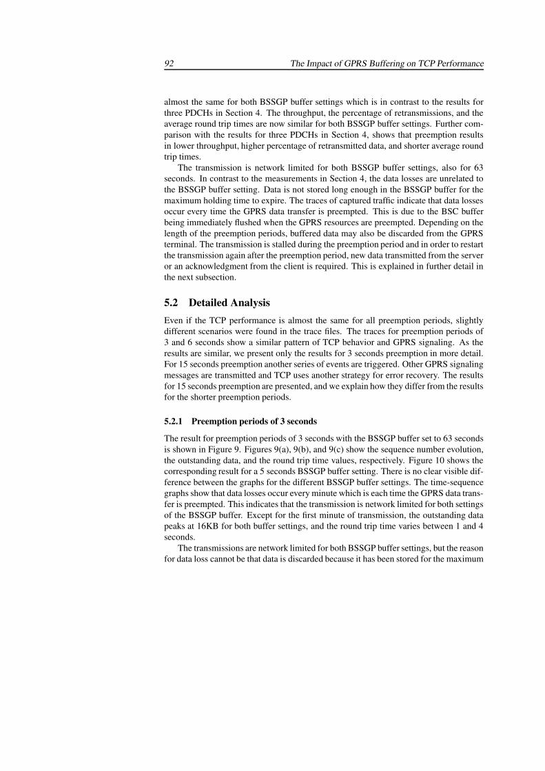
92 The Impact of GPRS Buffering on TCP Performance
almost the same for both BSSGP buffer settings which is in contrast to the results forthree PDCHs in Section 4. The throughput, the percentage of retransmissions, and theaverage round trip times are now similar for both BSSGP buffer settings. Further com-parison with the results for three PDCHs in Section 4, shows that preemption resultsin lower throughput, higher percentage of retransmitted data, and shorter average roundtrip times.
The transmission is network limited for both BSSGP buffer settings, also for 63seconds. In contrast to the measurements in Section 4, the data losses are unrelated tothe BSSGP buffer setting. Data is not stored long enough in the BSSGP buffer for themaximum holding time to expire. The traces of captured traffic indicate that data lossesoccur every time the GPRS data transfer is preempted. This is due to the BSC bufferbeing immediately flushed when the GPRS resources are preempted. Depending on thelength of the preemption periods, buffered data may also be discarded from the GPRSterminal. The transmission is stalled during the preemption period and in order to restartthe transmission again after the preemption period, new data transmitted from the serveror an acknowledgment from the client is required. This is explained in further detail inthe next subsection.
5.2 Detailed AnalysisEven if the TCP performance is almost the same for all preemption periods, slightlydifferent scenarios were found in the trace files. The traces for preemption periods of3 and 6 seconds show a similar pattern of TCP behavior and GPRS signaling. As theresults are similar, we present only the results for 3 seconds preemption in more detail.For 15 seconds preemption another series of events are triggered. Other GPRS signalingmessages are transmitted and TCP uses another strategy for error recovery. The resultsfor 15 seconds preemption are presented, and we explain how they differ from the resultsfor the shorter preemption periods.
5.2.1 Preemption periods of 3 seconds
The result for preemption periods of 3 seconds with the BSSGP buffer set to 63 secondsis shown in Figure 9. Figures 9(a), 9(b), and 9(c) show the sequence number evolution,the outstanding data, and the round trip time values, respectively. Figure 10 shows thecorresponding result for a 5 seconds BSSGP buffer setting. There is no clear visible dif-ference between the graphs for the different BSSGP buffer settings. The time-sequencegraphs show that data losses occur every minute which is each time the GPRS data trans-fer is preempted. This indicates that the transmission is network limited for both settingsof the BSSGP buffer. Except for the first minute of transmission, the outstanding datapeaks at 16KB for both buffer settings, and the round trip time varies between 1 and 4seconds.
The transmissions are network limited for both BSSGP buffer settings, but the reasonfor data loss cannot be that data is discarded because it has been stored for the maximum
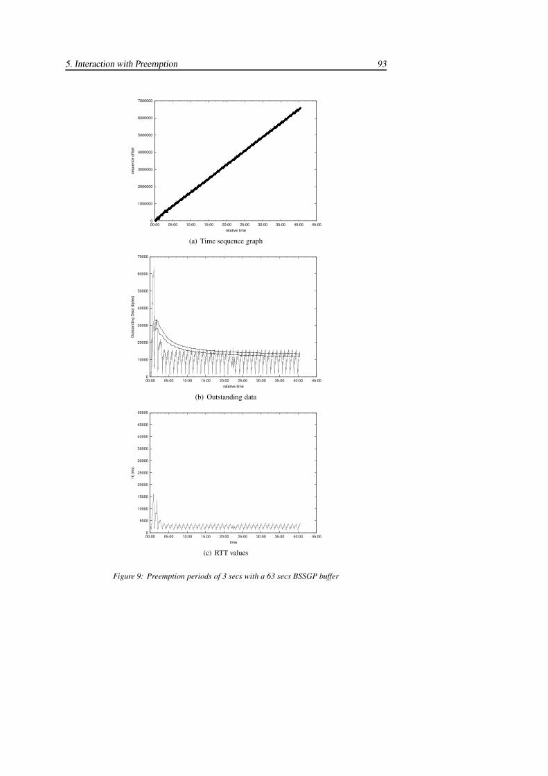
5. Interaction with Preemption 93
0
1000000
2000000
3000000
4000000
5000000
6000000
7000000
00:00 05:00 10:00 15:00 20:00 25:00 30:00 35:00 40:00 45:00
sequ
ence
offs
et
relative time
12121212121212
SYNSRSR3SRSRSRSRSRSRSRSRSSSSSSSSSSS
SRSR3SRSRSRSRSRSRSRSRSRSRSR3SRSRSRSR3SRSRSRSRSRS
RSRSRSRSRSRSRSRRSSRSRSRSRSRSRSRSR
RSSRSRSRSRSRSRSRSRRSSRSRSRSRSRSRSRSR
RSSRSRSRSRSRSRSRSRRSSRSRSRSRSRSRSRSR
RSSRSRSRSRSRSRSRSRRSSRSRSRSRSRSRSRSR
RSSRSRSRSRSRSRSRSRRSSRSRSRSRSRSRSRSR
RSSRSRSRSRSRSRSRSRRSSRSRSRSRSRSRSRSR
RSRSRSRSRSRSRSRRSRSRSRSRSRSRSR
RSSRSRSRSRSRSRSRSRRSSRSRSRSRSRSRSRSR
RSSRSRSRSRSRSRSRSRRRSRRRRRRRRSSR3SS
RSSRSRSRSRSRRSSRSRSRSRSRSRSRSR
RSSRSRSRSRSRSRSRSRRSRSRSRSRSRSRSR
RSSRSRSRSRSRSRSRSRRSSRSRSRSRSRSRSRSR
RSSRSRSRSRSRSRSRSRRSSRSRSRSRSRSRSRSR
RSSRSRSRSRSRSRSRSRRSSRSRSRSRSRSRSRSR
RSSRSRSRSRSRSRSRSRRSSRSRSRSRSRSRSRSR
RSSRSRSRSRSRSRSRSRRSSRSRSRSRSRSR
RSSRSRSRSRSRSRSRSRRSSRSRSRSRSRSRSRSR
RSSRSRSRSRSRSRSRSRFIN
(a) Time sequence graph
0
10000
20000
30000
40000
50000
60000
70000
00:00 05:00 10:00 15:00 20:00 25:00 30:00 35:00 40:00 45:00
Out
stan
ding
Dat
a (b
ytes
)
relative time
(b) Outstanding data
0
5000
10000
15000
20000
25000
30000
35000
40000
45000
50000
00:00 05:00 10:00 15:00 20:00 25:00 30:00 35:00 40:00 45:00
rtt (m
s)
time
(c) RTT values
Figure 9: Preemption periods of 3 secs with a 63 secs BSSGP buffer
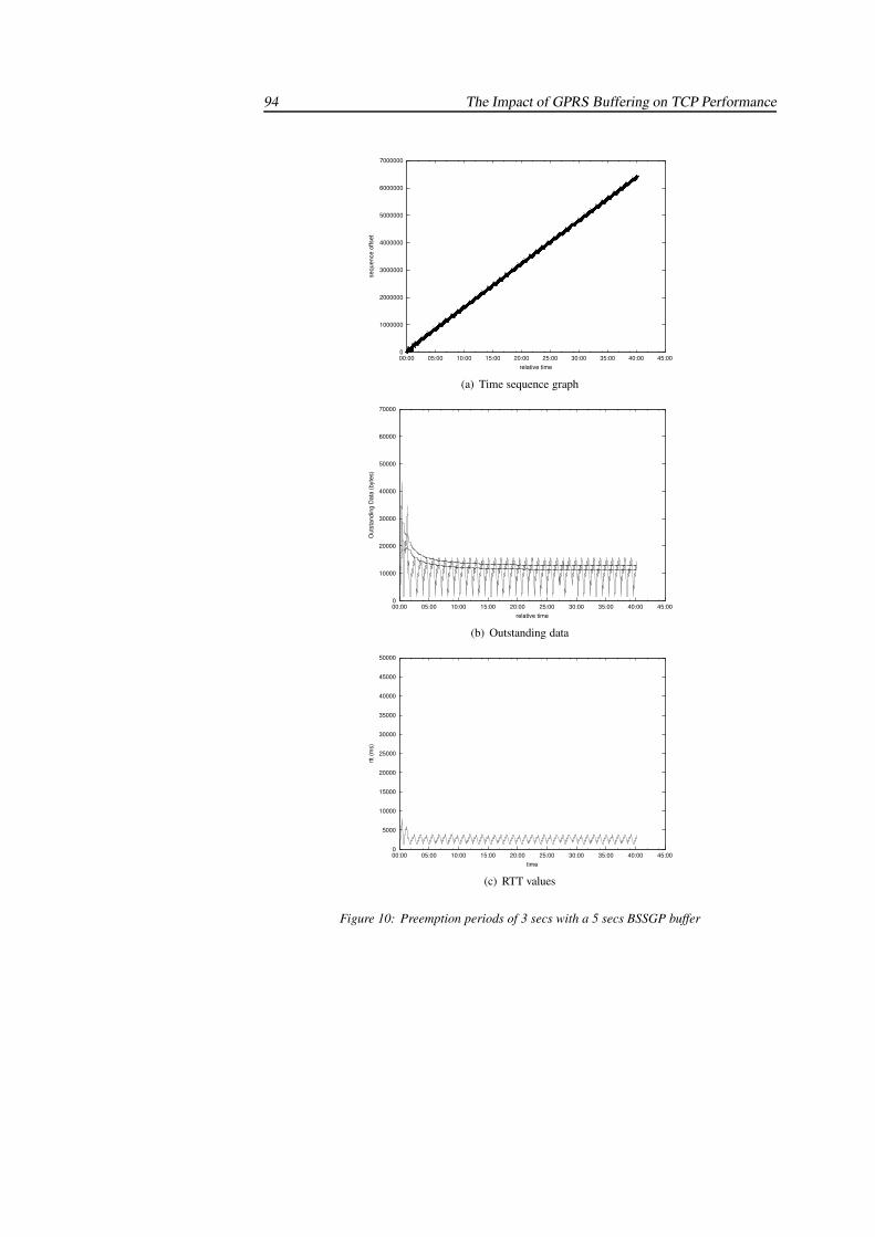
94 The Impact of GPRS Buffering on TCP Performance
0
1000000
2000000
3000000
4000000
5000000
6000000
7000000
00:00 05:00 10:00 15:00 20:00 25:00 30:00 35:00 40:00 45:00
sequ
ence
offs
etrelative time
121231231231231231231231231231231231212
SYNSSRSR3SRSRSRSRSRSRSRSRSRSRSRSRSRSSR3SSSSSSRSRSRSRSRSRSRSRSR
RSSRSRSRSRSRSRSRSRRSSRSRSRSRSRSRSRSR
RSSRSRSRSRSRSRSRSRRSSRSRSRSRSRSRSRSR
RSSRSRSRSRSRSRSRSRRSSRSRSRSRSRSRSRSR
RSSRSRSRSRSRSRSRSRRSSRSRSRSRSRSRSRSR
RSSRSRSRSRSRSRSRSRRSSRSRSRSRSRSRSRSR
RSSRSRSRSRSRSRSRSRRSSRSRSRSRSRSRSRSR
RSSRSRSRSRSRSRSRSRRSSRSRSRSRSRSRSRSR
RSRSRSRSRSRSRSRRSSRSRSRSRSRSRSRSRSRSSRSRSRSRSRSRSRSR
RSSRSRSRSRSRSRSRSRRSSRSRSRSRSRSRSRSR
RSSRSRSRSRSRSRSRSRSRSSRSRSRSRSRSRSRSR
RSSRSRSRSRSRSRSRSRRSSRSRSRSRSRSRSRSR
RSRSRSRRSRRSRRRSRSRSRSRSRSRSRSR
RSRSRSRRSRRSRRRSRSSRSRSRSRSRSRSRSRS
RSSRSRSRSRSRSRSRSRRSSRSRSRSRSRSRSRSR
RSSRSRSRSRSRSRSRSRRSSRSRSRSRSRSRSRSR
RSSRSRSRSRSRSRSRSRRSSRSRSRSRSRSRSRSR
RSSRSRSRSRSRSRSRSRRSSRSRSRSRSRSRSRSR
RSSRSRSRSRSRSRSRSRFIN
(a) Time sequence graph
0
10000
20000
30000
40000
50000
60000
70000
00:00 05:00 10:00 15:00 20:00 25:00 30:00 35:00 40:00 45:00
Out
stan
ding
Dat
a (b
ytes
)
relative time
(b) Outstanding data
0
5000
10000
15000
20000
25000
30000
35000
40000
45000
50000
00:00 05:00 10:00 15:00 20:00 25:00 30:00 35:00 40:00 45:00
rtt (m
s)
time
(c) RTT values
Figure 10: Preemption periods of 3 secs with a 5 secs BSSGP buffer
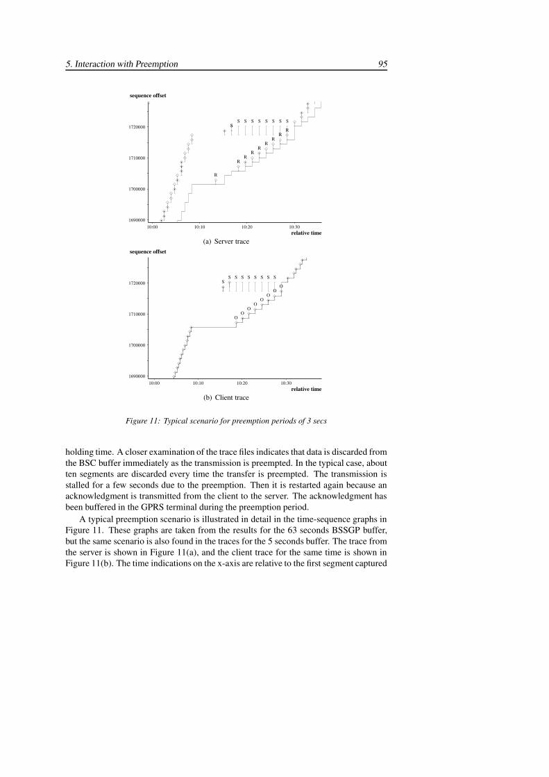
5. Interaction with Preemption 95
1720000
1710000
1700000
1690000 10:30 10:20 10:10 10:00
sequence offset
relative time
������RS
�RS
�RS
�R
S
�R
S
�R
S
�R
S
�R
S�S�
�R
��������������������
(a) Server trace
1720000
1710000
1700000
1690000 10:30 10:20 10:10 10:00
sequence offset
relative time
O
S
OS
OS
O
S
O
S
O
S
O
S
O
S S
(b) Client trace
Figure 11: Typical scenario for preemption periods of 3 secs
holding time. A closer examination of the trace files indicates that data is discarded fromthe BSC buffer immediately as the transmission is preempted. In the typical case, aboutten segments are discarded every time the transfer is preempted. The transmission isstalled for a few seconds due to the preemption. Then it is restarted again because anacknowledgment is transmitted from the client to the server. The acknowledgment hasbeen buffered in the GPRS terminal during the preemption period.
A typical preemption scenario is illustrated in detail in the time-sequence graphs inFigure 11. These graphs are taken from the results for the 63 seconds BSSGP buffer,but the same scenario is also found in the traces for the 5 seconds buffer. The trace fromthe server is shown in Figure 11(a), and the client trace for the same time is shown inFigure 11(b). The time indications on the x-axis are relative to the first segment captured
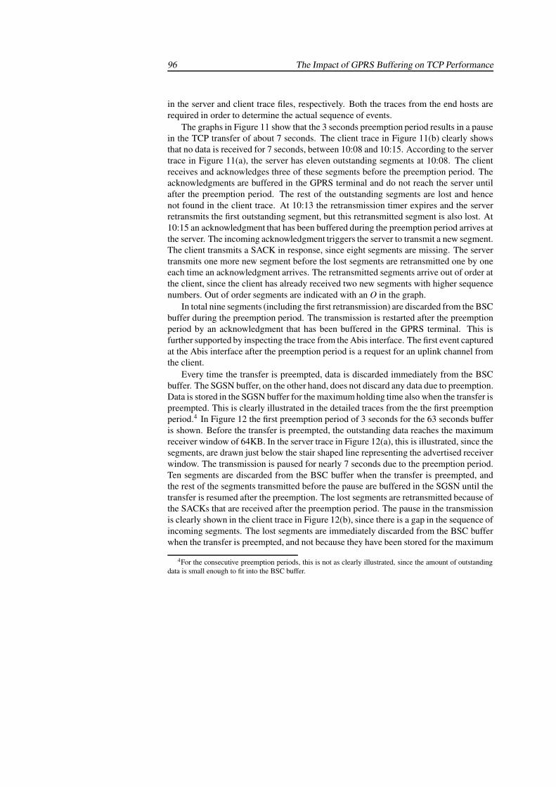
96 The Impact of GPRS Buffering on TCP Performance
in the server and client trace files, respectively. Both the traces from the end hosts arerequired in order to determine the actual sequence of events.
The graphs in Figure 11 show that the 3 seconds preemption period results in a pausein the TCP transfer of about 7 seconds. The client trace in Figure 11(b) clearly showsthat no data is received for 7 seconds, between 10:08 and 10:15. According to the servertrace in Figure 11(a), the server has eleven outstanding segments at 10:08. The clientreceives and acknowledges three of these segments before the preemption period. Theacknowledgments are buffered in the GPRS terminal and do not reach the server untilafter the preemption period. The rest of the outstanding segments are lost and hencenot found in the client trace. At 10:13 the retransmission timer expires and the serverretransmits the first outstanding segment, but this retransmitted segment is also lost. At10:15 an acknowledgment that has been buffered during the preemption period arrives atthe server. The incoming acknowledgment triggers the server to transmit a new segment.The client transmits a SACK in response, since eight segments are missing. The servertransmits one more new segment before the lost segments are retransmitted one by oneeach time an acknowledgment arrives. The retransmitted segments arrive out of order atthe client, since the client has already received two new segments with higher sequencenumbers. Out of order segments are indicated with an O in the graph.
In total nine segments (including the first retransmission) are discarded from the BSCbuffer during the preemption period. The transmission is restarted after the preemptionperiod by an acknowledgment that has been buffered in the GPRS terminal. This isfurther supported by inspecting the trace from the Abis interface. The first event capturedat the Abis interface after the preemption period is a request for an uplink channel fromthe client.
Every time the transfer is preempted, data is discarded immediately from the BSCbuffer. The SGSN buffer, on the other hand, does not discard any data due to preemption.Data is stored in the SGSN buffer for the maximum holding time also when the transfer ispreempted. This is clearly illustrated in the detailed traces from the the first preemptionperiod.4 In Figure 12 the first preemption period of 3 seconds for the 63 seconds bufferis shown. Before the transfer is preempted, the outstanding data reaches the maximumreceiver window of 64KB. In the server trace in Figure 12(a), this is illustrated, since thesegments, are drawn just below the stair shaped line representing the advertised receiverwindow. The transmission is paused for nearly 7 seconds due to the preemption period.Ten segments are discarded from the BSC buffer when the transfer is preempted, andthe rest of the segments transmitted before the pause are buffered in the SGSN until thetransfer is resumed after the preemption. The lost segments are retransmitted because ofthe SACKs that are received after the preemption period. The pause in the transmissionis clearly shown in the client trace in Figure 12(b), since there is a gap in the sequence ofincoming segments. The lost segments are immediately discarded from the BSC bufferwhen the transfer is preempted, and not because they have been stored for the maximum
4For the consecutive preemption periods, this is not as clearly illustrated, since the amount of outstandingdata is small enough to fit into the BSC buffer.
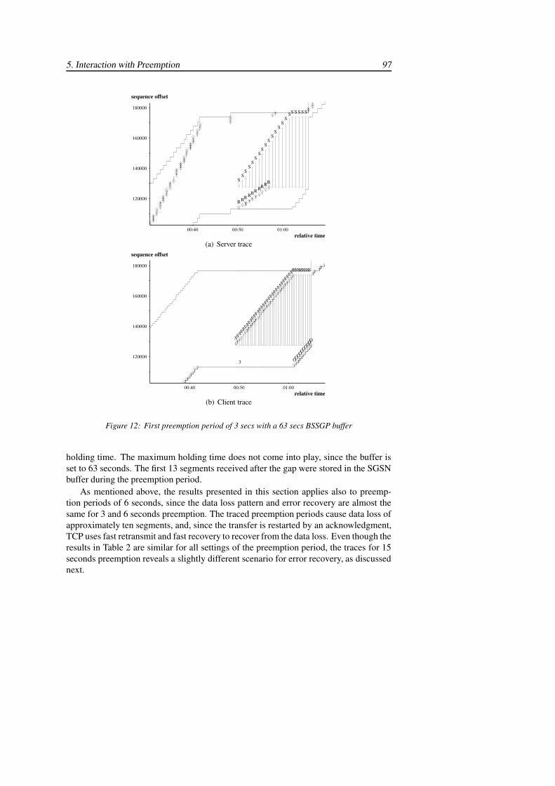
5. Interaction with Preemption 97
180000
160000
140000
120000
01:00 00:50 00:40
sequence offset
relative time
!!!!SSSSSS
SS
S
!
S
!
S
!R
S
!R
S
!R
S
!R
S
!R
S
!R
S
!R
S
!R
S
3!R
S
!R
S
!!!!!!!!!!!!!!!!!!!!!!!!!!!!!!!!!!!!!!!!!!!!!!!!
(a) Server trace
180000
160000
140000
120000
01:00 00:50 00:40
sequence offset
relative time
"""""
"O
S
"O
S
"O
S
"O
S
"O
S
"O
S
"O
S
"O
S
"O
S
"O
S"S"S"S"S"S"S"S"S"S"S"S"S"S"S"S"S"S"S"S"S"S"S"S"S"S"S"SSS
3
"S"S"
""""""""
(b) Client trace
Figure 12: First preemption period of 3 secs with a 63 secs BSSGP buffer
holding time. The maximum holding time does not come into play, since the buffer isset to 63 seconds. The first 13 segments received after the gap were stored in the SGSNbuffer during the preemption period.
As mentioned above, the results presented in this section applies also to preemp-tion periods of 6 seconds, since the data loss pattern and error recovery are almost thesame for 3 and 6 seconds preemption. The traced preemption periods cause data loss ofapproximately ten segments, and, since the transfer is restarted by an acknowledgment,TCP uses fast retransmit and fast recovery to recover from the data loss. Even though theresults in Table 2 are similar for all settings of the preemption period, the traces for 15seconds preemption reveals a slightly different scenario for error recovery, as discussednext.

98 The Impact of GPRS Buffering on TCP Performance
0
1000000
2000000
3000000
4000000
5000000
6000000
7000000
00:00 05:00 10:00 15:00 20:00 25:00 30:00 35:00 40:00 45:00
sequ
ence
offs
etrelative time
1212
12
SYNSRSR3SRSRSRSRSRSRSRSRSSSSSSSSSSSS
RSSRSR3SRSRSRSRSRSRSRSRSRSRSR3SRSRSRSRSRSRSRSRSSR
RRRRSRRRRRRRRRRSRRRRRRRRR
SSRS3SSSRRSRRRRRSRRRRRRRR
RSSRSRSRSRSRSRSRSRSRSRRRSRRRRRRRR
RSSRSRSRSRSRSRSRSRSRSRRRSRRRRRRRR
RRSRRRRRRRRRRSRSRSRSRSRSRSRSRSR
RRRRSRRRRRRRRSRSRSRSRSRSRSRSRSRSR
RRRRSRRRRRRRRRSSRSRSRSRSRSRSRSRSRSR
RRSRRRRRRRRRRRRSRRRRRRR
RSSRSRSRSRSRSRSRSRSRSRRRSRRRRRRRR
SSR3SSSSRRSRRRSSR3SRRSRRRRRR
RRRRSRRRRRRRRRSRSRSRSRSRSRSRSRSRSR
RRSRRRRRRRRRSSRSRSRSRSRSRSRSRSRSR
RRSRRRRRRRRRRRRSRRSRRRRRRR
RSSRSRSRSRSRSRSRSRSRSRRRSRRRRRRR
RRRRSSSRRRSRRSRRRSSFIN
(a) Time sequence graph
0
10000
20000
30000
40000
50000
60000
70000
00:00 05:00 10:00 15:00 20:00 25:00 30:00 35:00 40:00 45:00
Out
stan
ding
Dat
a (b
ytes
)
relative time
(b) Outstanding data
0
5000
10000
15000
20000
25000
30000
35000
40000
45000
50000
00:00 05:00 10:00 15:00 20:00 25:00 30:00 35:00 40:00 45:00
rtt (m
s)
time
(c) RTT values
Figure 13: Preemption periods of 15 secs with a 63 secs BSSGP buffer

5. Interaction with Preemption 99
0
1000000
2000000
3000000
4000000
5000000
6000000
7000000
00:00 05:00 10:00 15:00 20:00 25:00 30:00 35:00 40:00 45:00
sequ
ence
offs
et
relative time
1212312312312312312312312312
SYNSRSR3SRSRSRSRSRSRSRSRSRSSRSRSRSRRRSRRRRRRR
RRSRRRRRRRRRRSRRRRRRRRR
RRSRRRRRRRRRRRRSRRRRRRRRRR
RRSRRRRRRRRRRRSRRRRRRRRR
RRSRRRRRRRRRRSRRRRRRRRRRR
RRSRRRRRRRRRRRRSRRRRRRRRR
RRSRRRRRRRRRRRSRRRRRRRRRRR
RRSRRRRRRRRRRSRRRRRRRRRR
SSR3SSSSRRSRRRRRRRSRRRRRRRR
RRSRRRRRRRRRRRRSRRRRRRRRRR
RRSRRRRRRRRRRRSRRRRRRRRR
RRSRRRRRRRRRRRRRSRRRRRRRRRR
RRSRRRRRRRRRRSRRSRRRRRRRRRR
RRSRRRRRRRRRRRSRRRRRRRRRRR
RRSRRRRRRRRRRRRSRRRRRRRRR
RRSRRRRRRRRRRRRSRRRRRRRRR
RRSRRRRRRRRRRFIN
(a) Time sequence graph
0
10000
20000
30000
40000
50000
60000
70000
00:00 05:00 10:00 15:00 20:00 25:00 30:00 35:00 40:00 45:00
Out
stan
ding
Dat
a (b
ytes
)
relative time
(b) Outstanding data
0
5000
10000
15000
20000
25000
30000
35000
40000
45000
50000
00:00 05:00 10:00 15:00 20:00 25:00 30:00 35:00 40:00 45:00
rtt (m
s)
time
(c) RTT values
Figure 14: Preemption periods of 15 secs with a 5 secs BSSGP buffer
100 The Impact of GPRS Buffering on TCP Performance
5.2.2 Preemption periods of 15 seconds
The behavior of TCP is similar for both BSSGP buffer settings also for 15 secondspreemption. Figure 13 and Figure 14 show the results for BSSGP buffer settings of 63and 5 seconds, respectively. The results in the graphs are similar to those for 3 and6 seconds preemption described in the previous section. The outstanding data reaches16KB, and the round trip time peaks at 4 seconds. Higher values are only reached oncebefore the first preemption period. Preemption of 15 seconds also causes data loss inthe BSC of approximately ten segments. In the typical case a preemption period of 15seconds is long enough to cause timer-driven retransmission and slow start instead offast retransmit and fast recovery. The transmission is restarted by a retransmission fromthe server rather than by an acknowledgment from the client.
Figure 15 shows a typical scenario from the server and client traces of 15 secondspreemption for a BSSGP buffer setting of 63 seconds. A similar scenario occurs alsofor a 5 seconds BSSGP buffer. The server trace in Figure 15(a) shows that during the15 seconds preemption period the server times out twice before acknowledgments startto come back from the client. The client trace in Figure 15(b) shows that, after thepreemption period, the second retransmission arrives as a duplicated segment (indicatedwith an R). The client transmits an acknowledgment in response to the retransmittedsegment. A comparison between the server and client traces indicates that nine segments(including the first retransmission) are lost due to the preemption, and that the timeout events cause the server to enter a slow start phase in which the lost segments areretransmitted.
In contrast to the typical scenario for the shorter preemption periods, the first eventafter the preemption is a retransmission from the server, not an acknowledgment fromthe client. The preemption period of 15 seconds is long enough for the GPRS terminal toempty its buffer, and therefore there are no buffered acknowledgments to transmit afterthe preemption period. The Nethawk trace from the Abis interface supports this sce-nario, since it indicates that the second retransmission triggers a request for a downlinkchannel as the first event after the preemption period.
As for 3 seconds preemption, the preemption period of 15 seconds also causes loss ofnearly ten segments. It would be reasonable to expect the error recovery to take longer tocomplete after a preemption period of 15 seconds than for a shorter preemption period.This is however not the case. It takes approximately 20 seconds in both cases from thebeginning of the pause in the transmission until all the lost segments are recovered. Forthe shorter preemption periods of 3 and 6 seconds, incoming acknowledgments triggerfast retransmit and fast recovery, and for 15 seconds preemption the server times outand uses slow start instead. Since nearly ten consecutive segments are lost, slow start ismore efficient than fast retransmit and fast recovery which compensates for the longerpreemption period.
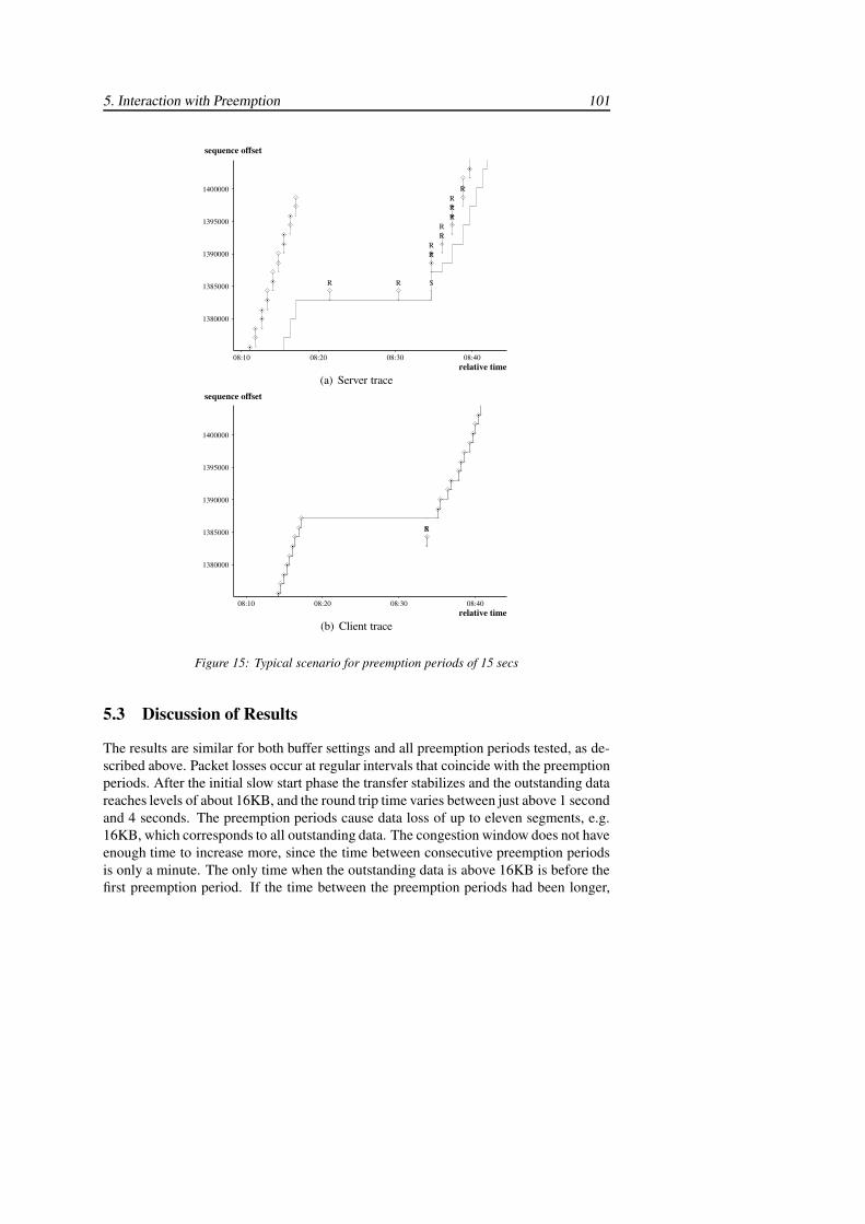
5. Interaction with Preemption 101
1400000
1395000
1390000
1385000
1380000
08:40 08:30 08:20 08:10
sequence offset
relative time
####R#R#R#R#R#R#R#RS#R#R
#################
(a) Server trace
1400000
1395000
1390000
1385000
1380000
08:40 08:30 08:20 08:10
sequence offset
relative time
$$$$$$$$$$$S$R
$$$$$$$$$
(b) Client trace
Figure 15: Typical scenario for preemption periods of 15 secs
5.3 Discussion of Results
The results are similar for both buffer settings and all preemption periods tested, as de-scribed above. Packet losses occur at regular intervals that coincide with the preemptionperiods. After the initial slow start phase the transfer stabilizes and the outstanding datareaches levels of about 16KB, and the round trip time varies between just above 1 secondand 4 seconds. The preemption periods cause data loss of up to eleven segments, e.g.16KB, which corresponds to all outstanding data. The congestion window does not haveenough time to increase more, since the time between consecutive preemption periodsis only a minute. The only time when the outstanding data is above 16KB is before thefirst preemption period. If the time between the preemption periods had been longer,
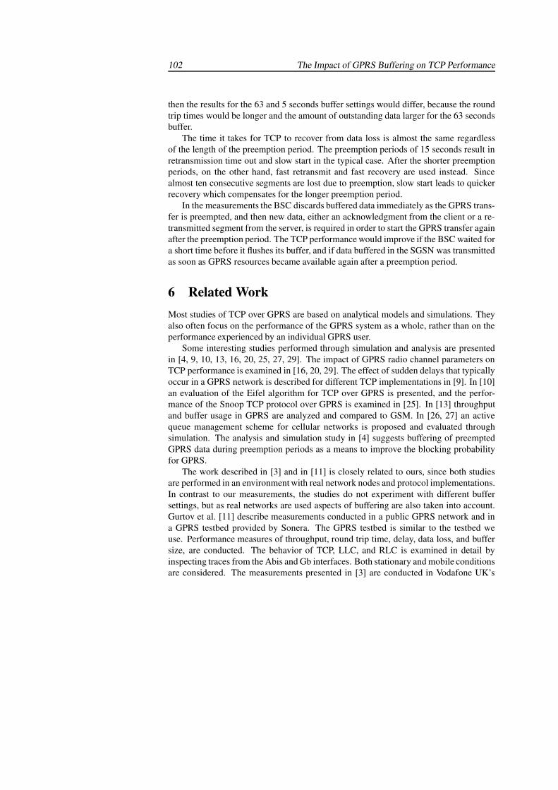
102 The Impact of GPRS Buffering on TCP Performance
then the results for the 63 and 5 seconds buffer settings would differ, because the roundtrip times would be longer and the amount of outstanding data larger for the 63 secondsbuffer.
The time it takes for TCP to recover from data loss is almost the same regardlessof the length of the preemption period. The preemption periods of 15 seconds result inretransmission time out and slow start in the typical case. After the shorter preemptionperiods, on the other hand, fast retransmit and fast recovery are used instead. Sincealmost ten consecutive segments are lost due to preemption, slow start leads to quickerrecovery which compensates for the longer preemption period.
In the measurements the BSC discards buffered data immediately as the GPRS trans-fer is preempted, and then new data, either an acknowledgment from the client or a re-transmitted segment from the server, is required in order to start the GPRS transfer againafter the preemption period. The TCP performance would improve if the BSC waited fora short time before it flushes its buffer, and if data buffered in the SGSN was transmittedas soon as GPRS resources became available again after a preemption period.
6 Related WorkMost studies of TCP over GPRS are based on analytical models and simulations. Theyalso often focus on the performance of the GPRS system as a whole, rather than on theperformance experienced by an individual GPRS user.
Some interesting studies performed through simulation and analysis are presentedin [4, 9, 10, 13, 16, 20, 25, 27, 29]. The impact of GPRS radio channel parameters onTCP performance is examined in [16, 20, 29]. The effect of sudden delays that typicallyoccur in a GPRS network is described for different TCP implementations in [9]. In [10]an evaluation of the Eifel algorithm for TCP over GPRS is presented, and the perfor-mance of the Snoop TCP protocol over GPRS is examined in [25]. In [13] throughputand buffer usage in GPRS are analyzed and compared to GSM. In [26, 27] an activequeue management scheme for cellular networks is proposed and evaluated throughsimulation. The analysis and simulation study in [4] suggests buffering of preemptedGPRS data during preemption periods as a means to improve the blocking probabilityfor GPRS.
The work described in [3] and in [11] is closely related to ours, since both studiesare performed in an environment with real network nodes and protocol implementations.In contrast to our measurements, the studies do not experiment with different buffersettings, but as real networks are used aspects of buffering are also taken into account.Gurtov et al. [11] describe measurements conducted in a public GPRS network and ina GPRS testbed provided by Sonera. The GPRS testbed is similar to the testbed weuse. Performance measures of throughput, round trip time, delay, data loss, and buffersize, are conducted. The behavior of TCP, LLC, and RLC is examined in detail byinspecting traces from the Abis and Gb interfaces. Both stationary and mobile conditionsare considered. The measurements presented in [3] are conducted in Vodafone UK’s
6. Related Work 103
public GPRS network. The characteristics of GPRS links are examined, and the impactof excessive buffering on TCP behavior is illustrated and explained.
According to [3] and [11], the over-sized network buffers used in many commercialnetworks may result in very long round trip times when the buffers in the GPRS networkare filled. The buffering in Sonera’s GPRS network is measured to 50KB for tests withTCP [11], and tests with UDP reported in [3] indicate that over 120KB of UDP data canbe buffered in Vodafone UK’s GPRS network. In [11] it is suggested that the optimalbuffering per user is 5-10 packets, i.e. 7-15KB, in a GPRS network with a bandwidth-delay product of less than 5KB.
In [3] a proxy between the GPRS network and the fixed network is proposed, as ameans to reduce the amount of buffered data. The proxy splits the TCP connection intotwo connections and uses a technique called TCP cwnd clamping. The congestion win-dow used on the proxy side of the GPRS network is set to a fixed value which is closerto the bandwidth-delay product for the radio link. The proxy also sets the advertisedreceiver window in the acknowledgments going back to the TCP sender in order to limitbuffering in the proxy.
Other authors also suggest adjustment of the advertised receiver window as a sim-ple solution to limit the maximum amount of data TCP transmits to the GPRS network.The advertised receiver window could either be set once before a TCP connection isestablished [21], or it could be adjusted dynamically based on information about theradio channel from lower layers [17]. The advantage of adjusting the advertised re-ceiver window is that it does not require any modification to the GPRS network, but thedisadvantage is that all GPRS clients must be configured.
In [26, 27] an active queue management scheme is proposed as a means to avoidover-buffering in cellular networks, such as GPRS and third generation cellular net-works. In contrast to other active queue management schemes, the proposed schemeuses the bandwidth-delay product of the wireless link to limit the instantaneous queuesize. It also applies a deterministic dropping policy. The scheme is evaluated with goodresults in a simulated third generation cellular network.
The problem with long round trip times as a result of excessive buffering is also il-lustrated by our measurements. Furthermore, our measurements indicate that queuingdelays can be reduced without much negative effect on throughput, if the BSSGP bufferis decreased. This implies that it may not be necessary to use active queue manage-ment, add a proxy, or modify the advertised receiver window in order to improve TCPperformance. The operators could easily adjust the BSSGP buffer setting to a smallermaximum holding time instead.
In [11] mobility and cell re-selection are examined, both in the testbed and in thepublic network provided by Sonera. The measurements in the public network indicatethat the GPRS data transfer is stopped for 3 to 15 seconds, when cell re-selection occurs.In the test network cell re-selection lasts for 2-5 seconds. Cell re-selection causes dataloss of about ten TCP segments in the downlink, because data buffered in the BSC isdiscarded instead of being transmitted to the new cell.
104 The Impact of GPRS Buffering on TCP Performance
The preemption periods tested in our measurements are similar to the time it takesfor cell re-selection to complete. Cell re-selection seems to have a similar impact onTCP performance as preemption, since the BSC discards all buffered data in both cases.In the preemption case, TCP performance would suffer less if buffered data was guardedby a timer before it is discarded or if data was buffered until resources for GPRS trafficbecome available again after the preemption period. As long as traffic classes are dif-ferentiated and preemptive priority is applied, problems related to preemption must betaken into account.
7 Conclusions and Future WorkIn this paper we experimentally evaluate TCP performance over GPRS. In particularwe investigate the impact of buffering in the GPRS network on TCP performance. Thesetting of the BSSGP buffer does not appear to greatly influence TCP throughput. How-ever, a large BSSGP buffer may cause very high delays in the system. This may lead toproblems if interactive traffic is to coexist with bulk transfers. In our measurements aBSSGP buffer setting of 63 seconds leads to queuing delays of up to 48 seconds whena single PDCH is assigned to GPRS. In this situation a user that downloads a large webpage and decides to move on to another location would have to wait at least 48 secondsbefore data for the new page can start to appear. This is clearly an undesirable scenario.Measurements with a BSSGP buffer setting of 5 seconds indicate that smaller buffersettings can be used to reduce queuing delays with only marginal impact on throughput.
The impact of preemption on performance is also studied. We investigate what hap-pens when GPRS traffic is preempted by high priority traffic, i.e. circuit-switched calls.In this situation data that is buffered in the BSC is immediately discarded when theGPRS resources are lost. Data that is stored in the SGSN buffer remain in the systemuntil their maximum holding time expires. New data, either in the form of a retrans-mitted segment or in the form of an acknowledgment buffered in the GPRS terminal,is needed to start up the transfer again after the preemption period ends. Since severalTCP segments get lost when the BSC buffer is flushed it takes a substantial amount oftime to recover even for short preemption periods. For a preemption period of 3 secondsit normally takes over 20 seconds to recover. This problem could potentially be avoidedby applying a timeout period before flushing data from the BSC buffer when the GPRSresources are preempted. Another alternative would be to leave the data in the bufferuntil resources become available again. Data buffered in the SGSN buffer should alsobe immediately transmitted when resources for GPRS become available again.
A GPRS measurement testbed that combines the use of real network equipment andprotocol implementations with a precise control over radio channel conditions is usedfor the experiments. Unlike simulations and live measurements, the testbed supportsTCP performance measurements over a real GPRS network, yet it provides a repeat-able environment in which a wide range of parameter settings can be explored. At thesame time, we must be aware that the presented results are not directly applicable for
REFERENCES 105
all GPRS systems. Since the handling of buffering is partly system dependent, a testbedwith a different hardware and software configuration will produce different results. Still,we feel that real measurements in a controllable environment are invaluable for the un-derstanding and enhancement of TCP performance in the GPRS system.
Our plans for future work include further experiments with different buffer settingsand how these affect various application models. We also plan to examine TCP per-formance when the number of available PDCHs varies dynamically. Measurements ofmobility would allow for interesting comparison with the results from the preemptionmeasurements.
AcknowledgmentsThe authors would like to thank their partners at Telia Mobile AB. Thanks to BojneSvensson for his help in performing the measurements and to Jonas Eriksson for provid-ing valuable insights into the GPRS system. This work has been partly funded by theSwedish graduate school PCC++.
References[1] M. Allman, V. Paxson, and W. Stevens. RFC 2581: TCP congestion control, April
1999.
[2] C. Bettstetter, H.-J. Vogel, and J. Eberspacher. GSM phase 2+ general packet radioservice GPRS: Architecture, protocols, and air interface. IEEE CommunicationSurveys, 2(3), 1999.
[3] R. Chakravorty, J. Cartwright, and I. Pratt. Practical experience with TCP overGPRS. In Proceedings of IEEE Global Telecommunications Conference (GLOBE-COM ’02), volume 2, pages 1678–1682, Taipei, Taiwan, November 2002.
[4] W.-Y. Chen, J.-L. C. Wu, and H.-H. Liu. Performance analysis of radio resourceallocation in GSM/GPRS networks. In Proceedings of IEEE Vehicular Technol-ogy Conference (VTC-02 Fall), volume 3, pages 1461–1465, Vancouver, Canada,September 2002.
[5] Ethereal. A network protocol analyzer. http://www.ethereal.com/.
[6] ETSI. Digital Cellular Telecommunications System (Phase 2+), General PacketRadio Service, Overall description of the GPRS radio interface (GSM 03.64, v.7.0.0), 1998.
[7] ETSI. Digital cellular telecommunications system (Phase 2+); General PacketRadio Service (GPRS); Base Station System (BSS) - Serving GPRS Support Node
106 The Impact of GPRS Buffering on TCP Performance
(SGSN); BSS GPRS Protocol (BSSGP) (GSM 08.18 version 6.7.1 Release 1997),2000.
[8] ETSI. Digital cellular telecommunications system (Phase 2+); General PacketRadio Service (GPRS); Service description; Stage 2 (GSM 03.60 version 6.7.0Release 1997), 2000.
[9] A. Gurtov. Effect of delays on TCP performance. In Proceedings of IFIP PersonalWireless Communications, Lappeenranta, Finland, August 2001.
[10] A. Gurtov and R. Ludwig. Evaluating the Eifel algorithm for TCP in a GPRSnetwork. In Proceedings of European Wireless, Florence, Italy, February 2002.
[11] A. Gurtov, M. Passoja, O. Aalto, and M. Raitola. Multi-layer protocol tracingin a GPRS network. In Proceedings of IEEE Vehicular Technology Conference(VTC-02 Fall), volume 3, pages 1612–1616, Vancouver, Canada, September 2002.
[12] M. Handley, J. Padhye, and S. Floyd. RFC 2861: TCP congestion window valida-tion, June 2000.
[13] J. Ho, Y. Zhu, and S. Madhavapeddy. Throughput and buffer analysis for GSMgeneral packet radio service (GPRS). In IEEE Wireless Communications and Net-works Conference 1999 (WCNC’99), volume 3, pages 1427–1431, New Orleans,Louisiana, USA, 1999.
[14] H. Inamura, G. Montenegro, R. Ludwig, A. Gurtov, and F. Khafizov. RFC 3481:TCP over second (2.5G) and third (3G) generation wireless networks, February2003.
[15] V. Jacobson, R. Braden, and D. Borman. RFC 1323: TCP extensions for highperformance, May 1992.
[16] R. Kalden, I. Meirick, and M. Meyer. Wireless Internet access based on GPRS.IEEE Personal Communications, 7(2):8–18, April 2000.
[17] D.-S. Lee and C.-C. Lin. Window adaptive TCP for EGPRS networks. In Proceed-ings of the 5th International Symposium on Wireless Personal Multimedia Commu-nications, IEEE, volume 2, pages 853–857, Honolulu, Hawaii, October 2002.
[18] M. Mathis, J. Mahdavi, S. Floyd, and A. Romanow. RFC 2018: TCP selectiveacknowledgment options, October 1996.
[19] S. McCanne and V. Jacobson. The BSD packet filter: a new architecture for user-level packet capture. In Proceedings of the Winter 1993 USENIX Conference,pages 259–269, San Diego, California, USA, January 1993.
REFERENCES 107
[20] M. Meyer. TCP performance over GPRS. In Proceedings of IEEE Wireless Com-munications and Networking Conference (WCNC ’99), volume 3, pages 1248–1252, New Orleans, Louisiana, USA, September 1999.
[21] R. G. Mukhtar, S. V. Hanly, M. Ivanovich, P. Fitzpatrick, and H. L. Vu. Analysisof TCP performance over hybrid ”fast fixed - to - slow wireless” buffered links. InProceedings of IEEE Global Telecommunications Conference (GLOBECOM ’01),volume 3, pages 1816–1820, San Antonio, Texas, USA, November 2001.
[22] NetHawk. NetHawk GSM Analyser. http://www.nethawk.fi/.
[23] S. Ostermann. Tcptrace. http://www.tcptrace.org/.
[24] J. Postel. RFC 793: Transmission control protocol, September 1981.
[25] J. Rendon, F. Casadevall, and D. Serarols. Snoop TCP performance over GPRS.In Proceedings of IEEE Vehicular Technology Conference (VTC-01 Spring), vol-ume 3, pages 2103–2107, Rhodos, Greece, May 2001.
[26] M. Sagfors, R. Ludwig, M. Meyer, and J. Peisa. Buffer management for rate-varying 3G wireless links supporting TCP traffic. In Proceedings of IEEE Ve-hicular Technology Conference (VTC-03 Spring), volume 1, pages 675–679, Jeju,South Korea, April 2003.
[27] M. Sagfors, R. Ludwig, M. Meyer, and J. Peisa. Queue management for TCP trafficover 3G links. In Proceedings of IEEE Wireless Communications and Networking(WCNC ’03), volume 3, pages 1663–1668, New Orleans, Louisiana, USA, March2003.
[28] P. Sarolahti and A. Kuznetsov. Congestion control in Linux TCP. In USENIX An-nual Technical Conference, FREENIX Track, pages 49–62, Monterey, California,USA, June 2002.
[29] M. Taferner and E. Bonek. Wireless Internet Access over GSM and UMTS.Springer-Verlag, 2002.