Embed Size (px)
Citation preview
LARSA 4D Manual for the Steel Bridge Module
A manual for
LARSA 4DFinite Element Analysis and Design Software
Last Revised October 2016
Copyright (C) 2001-2016 LARSA, Inc. All rights reserved. Information in this document issubject to change without notice and does not represent a commitment on the part of LARSA,Inc. The software described in this document is furnished under a license or nondisclosureagreement. No part of the documentation may be reproduced or transmitted in any form or byany means, electronic or mechanical including photocopying, recording, or information storageor retrieval systems, for any purpose without the express written permission of LARSA, Inc.
LARSA 4D Manual for the Steel Bridge Module
Table of ContentsIntroduction 5
About This Manual 5
Capabilities of the Steel Bridge Module 7
Getting Started 9Using the Module 9
Getting Started 9
Bridge Alignment and Piers 11Structure Layout 11
Abutments and Piers 13
Girders, Cross Frames, and Splice Points 15Girders 15
Cross Frames and Related Geometry 17
The Deck and Generation Options 21Deck 21
Generation Options 21
Bridge Loading 23Live Load 23
Sidewalk 24
Miscellaneous Loads 24
Construction Loads 25
Code Check for AASHTO LRFD 27Code Check on an Existing Model 27
Code Check Locations 28
Load Cases 29
Girder Details 30
Running Code Check 30
Reports 31
Code Check Additional Parameters 33
3

LARSA 4D Manual for the Steel Bridge Module
4
LARSA 4D Manual for the Steel Bridge Module
Introduction
About This Manual
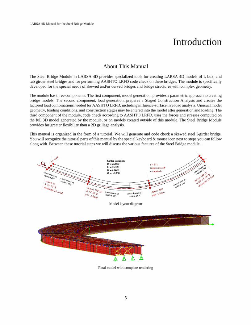
The Steel Bridge Module in LARSA 4D provides specialized tools for creating LARSA 4D models of I, box, andtub girder steel bridges and for performing AASHTO LRFD code check on these bridges. The module is specificallydeveloped for the special needs of skewed and/or curved bridges and bridge structures with complex geometry.
The module has three components: The first component, model generation, provides a parametric approach to creatingbridge models. The second component, load generation, prepares a Staged Construction Analysis and creates thefactored load combinations needed for AASHTO LRFD, including influence-surface live load analysis. Unusual modelgeometry, loading conditions, and construction stages may be entered into the model after generation and loading. Thethird component of the module, code check according to AASHTO LRFD, uses the forces and stresses computed onthe full 3D model generated by the module, or on models created outside of this module. The Steel Bridge Moduleprovides far greater flexibility than a 2D grillage analysis.
This manual is organized in the form of a tutorial. We will generate and code check a skewed steel I-girder bridge.You will recognize the tutorial parts of this manual by the special keyboard & mouse icon next to steps you can followalong with. Between these tutorial steps we will discuss the various features of the Steel Bridge module.
Model layout diagram
Final model with complete rendering
5
LARSA 4D Manual for the Steel Bridge Module
About LARSA 4D
LARSA 4D is an advanced multipurpose 3D structural analysis package featuring a powerful graphical user interfaceand an analysis engine with unmatched analytical features including influence line and surface based live load analysis,staged construction analysis, time-dependent material properties and segmental construction analysis, hysteretic andseismic elements and seismic analysis, and progressive collapse.
The LARSA structural analysis engine has been in commercial use for over 25 years. It was originally developedto perform nonlinear static analysis of structures that have large displacements, such as suspension and cable stayedbridges and guyed towers. The engine became popular for analyses of these types of structures because of itsunprecedented accuracy at a reasonable price. The engine has been powerful since day one, using both tangent stiffnessand the full Newton-Raphson method with iterations in nonlinear analysis. LARSA software has come a long waysince it was first available on the VAX super-mini computers decades ago.
LARSA, Inc. has always been an industry leader. LARSA was the first to offer an individual PC-based DOS structuralanalysis package with geometric nonlinear analysis capabilities in 1986. In 1994, LARSA took the early next step toMicrosoft Windows with a point-and-click graphical user interface and two years later was the first to offer elastic/perfectly plastic pushover analysis. Today, LARSA’s flagship product is LARSA 4D, released in 2006 and featuringnew seismic and inelastic elements, major improvements to influence and staged construction analysis, and many newfeatures for bridge design and analysis.
6

LARSA 4D Manual for the Steel Bridge Module
Capabilities of the Steel BridgeModule
Some of the capabilities of the Steel Bridge Module include:
Geometry
• Define complex curved bridge alignments using LARSA 4D bridge path coordinate systems.
• A 3D finite element model is created for accurate analysis and design.
• Provide skew angles and support conditions for each abutment, pier and cross-frame.
• Create I-girder, box girder, tub girder structures.
• Vary plate size and deck width along the length of the bridge.
• Start and end girders at any point along the bridge.
• Model bridges with cross-slope, splice points, lateral bracing, substrings, and hybrid girders.
• Refine the 3D finite element model by specifying the maximum side length of deck plate elements.
Loading
• Create AASHTO LRFD compatible live loading with vertical, centrifugal, and braking effects.
• Automatically generate side walk, barrier, parapet, bridge rail, pedestrian, future wearing surface, monoliticwearing surface, utility, and wind loading.
• Simulate the construction and pouring sequence of the girders and deck.
• Simulate the movement of the screed during construction.
• Account for stay-in-place or strippable deck formwork.
Analysis
• Analyze the construction sequence using LARSA 4D's staged construction analysis.
• Account for short-term and long-term concrete properties using LARSA 4D's time-dependent stagedconstruction analysis.
• Live load results are computed using influence surfaces.
• Compound Element Forces are used to extract sectional forces from girders modelled with multiple elements(web as plate, flanges as beam elements).
Code Check
• Perform AASHTO LRFD code checks on arbitrary steel girder bridge finite element models.
• Check construction, strength, servicability, fatigue, optional live load deflection check.
• Check cross-frames and substringers.
• Account for deck reinforcements and longitudinal, transverse, bearing, and box flange stiffeners.
• Provide a list of locations to be code checked.
7

LARSA 4D Manual for the Steel Bridge Module
• View detailed code-check reports at each location with step-by-step formulas.
• Create custom load classes and combinations.
• Account for permit live loading.
User Interface
• An intuitive interface with a step-by-step approach and powerful tabular data entry.
• Context aware help included within the interface, allowing the user to see the description of each input whileentering the values.
8
LARSA 4D Manual for the Steel Bridge Module
Getting Started
Using the Module
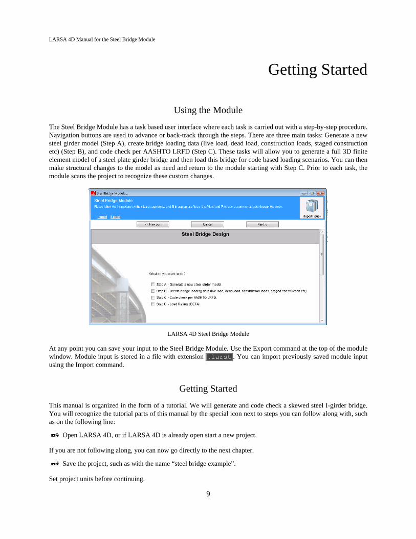
The Steel Bridge Module has a task based user interface where each task is carried out with a step-by-step procedure.Navigation buttons are used to advance or back-track through the steps. There are three main tasks: Generate a newsteel girder model (Step A), create bridge loading data (live load, dead load, construction loads, staged constructionetc) (Step B), and code check per AASHTO LRFD (Step C). These tasks will allow you to generate a full 3D finiteelement model of a steel plate girder bridge and then load this bridge for code based loading scenarios. You can thenmake structural changes to the model as need and return to the module starting with Step C. Prior to each task, themodule scans the project to recognize these custom changes.
LARSA 4D Steel Bridge Module
At any point you can save your input to the Steel Bridge Module. Use the Export command at the top of the modulewindow. Module input is stored in a file with extension .larst . You can import previously saved module inputusing the Import command.
Getting Started
This manual is organized in the form of a tutorial. We will generate and code check a skewed steel I-girder bridge.You will recognize the tutorial parts of this manual by the special icon next to steps you can follow along with, suchas on the following line:
Open LARSA 4D, or if LARSA 4D is already open start a new project.
If you are not following along, you can now go directly to the next chapter.
Save the project, such as with the name “steel bridge example”.
Set project units before continuing.
9
LARSA 4D Manual for the Steel Bridge Module
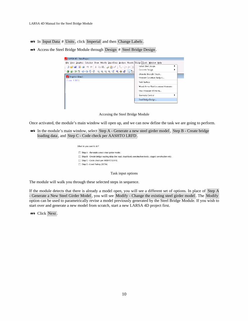
In Input Data # Units , click Imperial and then Change Labels .
Access the Steel Bridge Module through Design # Steel Bridge Design .
Accesing the Steel Bridge Module
Once activated, the module’s main window will open up, and we can now define the task we are going to perform.
In the module’s main window, select Step A - Generate a new steel girder model , Step B - Create bridgeloading data , and Step C - Code check per AASHTO LRFD .
Task input options
The module will walk you through these selected steps in sequence.
If the module detects that there is already a model open, you will see a different set of options. In place of Step A- Generate a New Steel Girder Model , you will see Modify - Change the existing steel girder model . The Modifyoption can be used to parametrically revise a model previously generated by the Steel Bridge Module. If you wish tostart over and generate a new model from scratch, start a new LARSA 4D project first.
Click Next .
10
LARSA 4D Manual for the Steel Bridge Module
Bridge Alignment and Piers
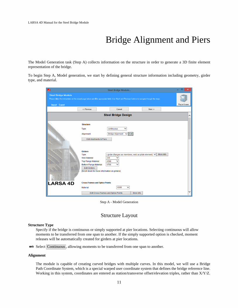
The Model Generation task (Step A) collects information on the structure in order to generate a 3D finite elementrepresentation of the bridge.
To begin Step A, Model generation, we start by defining general structure information including geometry, girdertype, and material.
Step A - Model Generation
Structure Layout
Structure TypeSpecify if the bridge is continuous or simply supported at pier locations. Selecting continuous will allowmoments to be transferred from one span to another. If the simply supported option is checked, momentreleases will be automatically created for girders at pier locations.
Select Continuous , allowing moments to be transferred from one span to another.
Alignment
The module is capable of creating curved bridges with multiple curves. In this model, we will use a BridgePath Coordinate System, which is a special warped user coordinate system that defines the bridge reference line.Working in this system, coordinates are entered as station/transverse offset/elevation triples, rather than X/Y/Z.
11
LARSA 4D Manual for the Steel Bridge Module
Station refers to the arc-distance along a reference line usually on the bridge deck. Transverse offset refers to theperpendicular distance from the reference line. And elevation is the vertical distance from the reference line.
Bridge Paths [in LARSA 4D Reference Manual] are defined by establishing a horizontal curve and a verticalcurve. The horizontal curve is composed of one or more straight-line, circular, or spiral segments between controlpoints. Control points are usually found on site plans with their station and bearing, which is entered into theSteel Bridge Module.
The elevation curve is composed of one or more straight or parabolic curves between elevation control points.The station, elevation, and grade at each elevation control point are given.
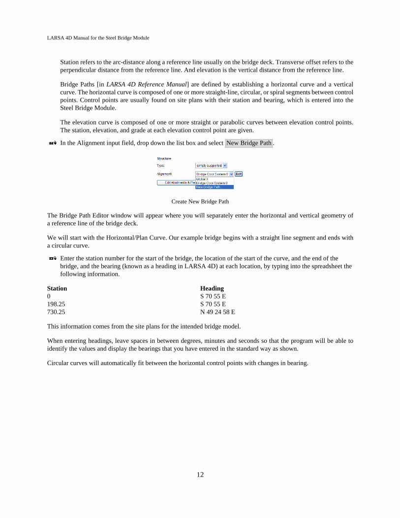
In the Alignment input field, drop down the list box and select New Bridge Path .
Create New Bridge Path
The Bridge Path Editor window will appear where you will separately enter the horizontal and vertical geometry ofa reference line of the bridge deck.
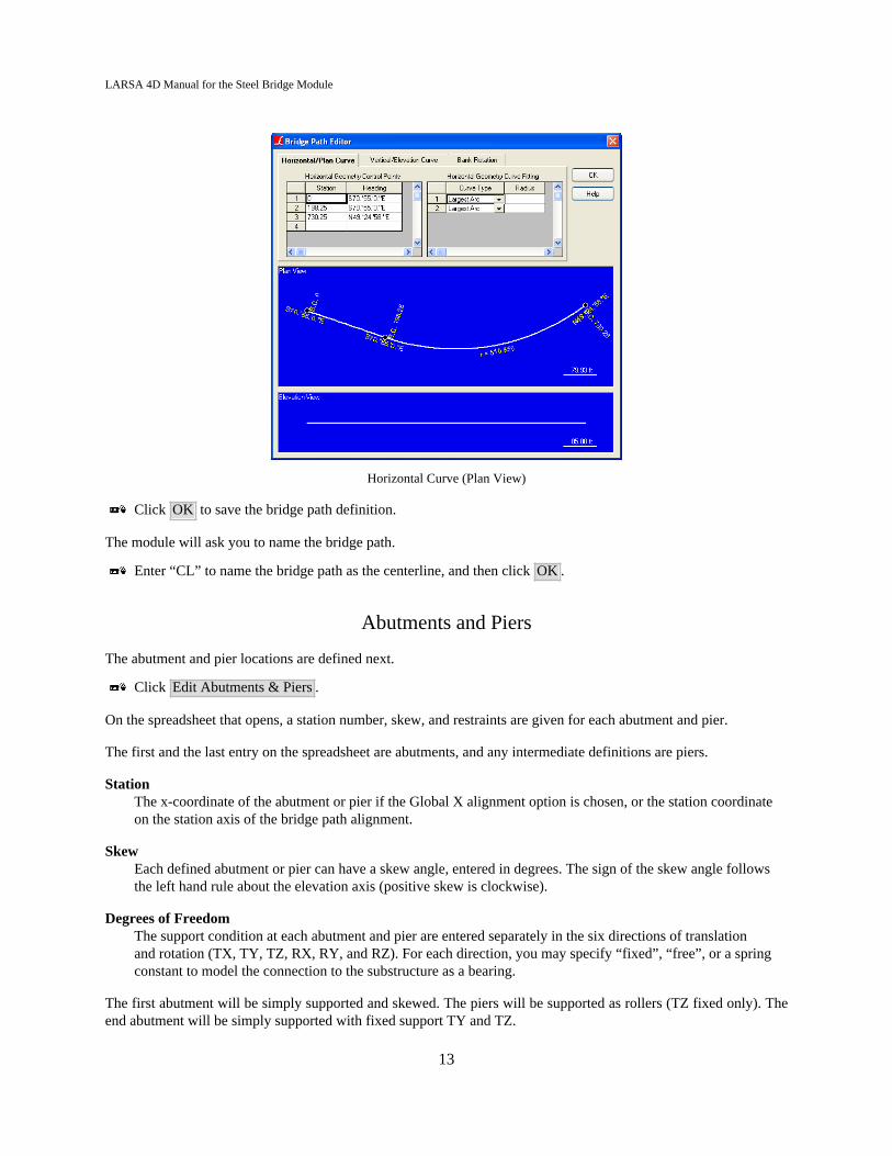
We will start with the Horizontal/Plan Curve. Our example bridge begins with a straight line segment and ends witha circular curve.
Enter the station number for the start of the bridge, the location of the start of the curve, and the end of thebridge, and the bearing (known as a heading in LARSA 4D) at each location, by typing into the spreadsheet thefollowing information.
Station Heading0 S 70 55 E198.25 S 70 55 E730.25 N 49 24 58 E
This information comes from the site plans for the intended bridge model.
When entering headings, leave spaces in between degrees, minutes and seconds so that the program will be able toidentify the values and display the bearings that you have entered in the standard way as shown.
Circular curves will automatically fit between the horizontal control points with changes in bearing.
12
LARSA 4D Manual for the Steel Bridge Module
Horizontal Curve (Plan View)
Click OK to save the bridge path definition.
The module will ask you to name the bridge path.
Enter “CL” to name the bridge path as the centerline, and then click OK .
Abutments and Piers
The abutment and pier locations are defined next.
Click Edit Abutments & Piers .
On the spreadsheet that opens, a station number, skew, and restraints are given for each abutment and pier.
The first and the last entry on the spreadsheet are abutments, and any intermediate definitions are piers.
StationThe x-coordinate of the abutment or pier if the Global X alignment option is chosen, or the station coordinateon the station axis of the bridge path alignment.
SkewEach defined abutment or pier can have a skew angle, entered in degrees. The sign of the skew angle followsthe left hand rule about the elevation axis (positive skew is clockwise).
Degrees of FreedomThe support condition at each abutment and pier are entered separately in the six directions of translationand rotation (TX, TY, TZ, RX, RY, and RZ). For each direction, you may specify “fixed”, “free”, or a springconstant to model the connection to the substructure as a bearing.
The first abutment will be simply supported and skewed. The piers will be supported as rollers (TZ fixed only). Theend abutment will be simply supported with fixed support TY and TZ.
13

LARSA 4D Manual for the Steel Bridge Module
Starting with the first abutment, enter the information as shown in the figure below.
Abutment and pier information
14
LARSA 4D Manual for the Steel Bridge Module
Girders, Cross Frames, and SplicePoints
Girders
Girder Type
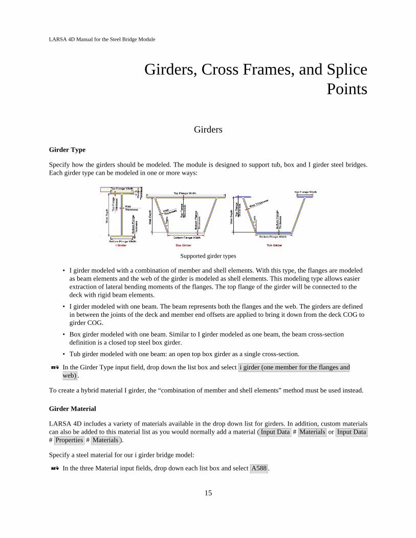
Specify how the girders should be modeled. The module is designed to support tub, box and I girder steel bridges.Each girder type can be modeled in one or more ways:
Supported girder types
• I girder modeled with a combination of member and shell elements. With this type, the flanges are modeledas beam elements and the web of the girder is modeled as shell elements. This modeling type allows easierextraction of lateral bending moments of the flanges. The top flange of the girder will be connected to thedeck with rigid beam elements.
• I girder modeled with one beam. The beam represents both the flanges and the web. The girders are definedin between the joints of the deck and member end offsets are applied to bring it down from the deck COG togirder COG.
• Box girder modeled with one beam. Similar to I girder modeled as one beam, the beam cross-sectiondefinition is a closed top steel box girder.
• Tub girder modeled with one beam: an open top box girder as a single cross-section.
In the Girder Type input field, drop down the list box and select i girder (one member for the flanges andweb) .
To create a hybrid material I girder, the “combination of member and shell elements” method must be used instead.
Girder Material
LARSA 4D includes a variety of materials available in the drop down list for girders. In addition, custom materialscan also be added to this material list as you would normally add a material ( Input Data # Materials or Input Data# Properties # Materials ).
Specify a steel material for our i girder bridge model:
In the three Material input fields, drop down each list box and select A588 .
15

LARSA 4D Manual for the Steel Bridge Module
Girder Properties
Click Edit Girders .
Just like abutment and pier locations, each girder needs to be defined. Girder Number must start with 1 for the rightmostgirder and go up consecutively from right to left.
Enter the information shown in the figure below. The girder number and transverse offsets are differentfor each girder. But the stations and the cross-section dimensions from Haunch Thickness to the end of thespreadsheet are the same for all four girders.
Girder information
Girder NumberGirder Number must start with 1 for the rightmost girder and go up consecutively from right to left. Thespreadsheet must have at least one row for each girder. However, it is possible to have more than that. Thesame girder number may need to be defined multiple times between different stations if the girder changes sizeor has varying transverse location along the bridge.
Begin Station/End StationWhen using a bridge path coordinate system, station refers to the position along the bridge centerline. For agirder with a transverse offset, the station is measured along the alignment centerline first. The transverse offsetis then applied perpendicularly from the alignment centerline.
Transverse Offset @ Start/EndUse these fields to specify the horizontal/transverse location of each girder, relative to the reference centerlineof the bridge (the Global X axis or the bridge path centerline, as appropriate). The values @ Start and @ Endmay differ but usually are the same. A value of zero places the girder on the reference centerline. For a bridgeorientated left-to-right, positive transverse offset values are either up (in plan) or into-the-screen (in elevation).(Positive values follow the right-hand-rule, with the 1st axis going in the direction (tangent) of the bridge, the2nd axis being the positive transverse offset axis, and the 3rd axis being the positive elevation axis.)
Haunch ThicknessThe extra spacing between the girder and the bottom of the deck. The haunch is included in the weight of thedeck but is ignored for stiffness.
Section DimensionsThe columns Web Depth, Web Thickness, Top Flange Width, Bottom Flange Width, Top Flange Thickness,and Bottom Flange Thickness specify the cross-section dimensions of the girder.
There are two other tabs above the spreadsheet where additional information may be entered. We will not use theadditional tabs in the tutorial, but they are used as follows:
Vertical OffsetThis tab allows you to put the deck on a transverse grade (cross slope). Use a positive offset to raise the deck bythat amount from the bridge reference line. For superelevation, consider also using Bank Rotation in the Bridge
16
LARSA 4D Manual for the Steel Bridge Module
Path Coordinate System. The vertical offset is typically the same at the start and end of each girder, but it canvary if the transverse grade (cross slope) varies along the length of the bridge.
Tub GirderOn this tab, additional section dimensions for tub girder bridges can be specified.
Click Back to Main Page to close the spreadsheet and continue with the Steel Bridge Module.
Cross Frames and Related Geometry
The next section is used to add cross frames, diaphragms, splice points, substringers, and lateral bracing.
As with abutment, piers, and girders, cross frames and splice points need to be defined if there are any. Specify thematerial, location, and type of cross frames, diaphragms, and splice points to be used between the girders.
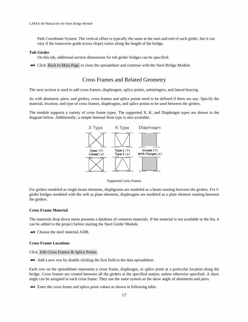
The module supports a variety of cross frame types. The supported X, K, and Diaphragm types are shown in thediagram below. Additionally, a simple Internal Strut type is also available..
Supported cross frames
For girders modeled as single beam elements, diaphgrams are modeled as a beam running between the girders. For I-girder bridges modeled with the web as plate elements, diaphragms are modeled as a plate element running betweenthe girders.
Cross Frame Material
The materials drop down menu presents a database of common materials. If the material is not available in the list, itcan be added to the project before starting the Steel Girder Module.
Choose the steel material A588.
Cross Frame Locations
Click Edit Cross Frames & Splice Points .
Add a new row by double clicking the first field in the data spreadsheet.
Each row on the spreadsheet represents a cross frame, diaphragm, or splice point at a particular location along thebridge. Cross frames are created between all the girders at the specified station, unless otherwise specified. A skewangle can be assigned to each cross frame. They use the same system as the skew angle of abutments and piers.
Enter the cross frame and splice point values as shown in following table.
17

LARSA 4D Manual for the Steel Bridge Module
Station (ft) Type Dist. from Bot.of Top. Flange(in)
Depth (in) Skew Location Bays
24 X Type (Open) 10 73 0 External 1-3100 X Type (Open) 10 73 0 External ALL198.25 X Type (Open) 10 73 0 External ALL293.625 X Type (Open) 10 73 0 External ALL393.625 X Type (Open) 10 73 0 External ALL469 X Type (Open) 10 73 0 External ALL619.625 X Type (Open) 10 73 0 External ALL670 X Type (Open) 10 73 0 External ALL730.25 X Type (Open) 10 73 0 External ALL
StationThe location of the cross frame, diaphragm, or splice point.
TypeThe type of cross frame or diaphragm, or if this entry is for a splice point. A splice point ensures that jointsare placed at this location in the finite element model but does not generate a cross-frame or diaphragm at thatlocation.
Distance from Bottom of Top FlangeSets the location of the top of the cross-frame, girder, or internal strut. The distance is measured from thebottom of the top flange of the girder to the centroid of the top struts of the cross frame, the top of thediaphragm, or the centroid of the internal strut. Not used for splice points.
DepthThe depth of the cross frame or diaphragm. Typically slightly less than the web depth. Not used for internalstruts or splice points.
SkewIf the cross frame, diaphragm, or splice point is on a skew, the skew angle in degrees (measured clockwise, orthe left-hand-rule) is given. When a skew is used, the station is measured at the location where cross frame,diaphragm, or splice point intersects the Global X axis or bridge path reference line (as appropriate).
LocationFor tub and box girders, specifies whether the diaphragm is only external or both internal and external to thetub/box. This field is not used for I-girders or for cross-frames and splice points.
BaysSpecifies the bays between the girders in which this cross frame is applied. Enter ALL to place the cross framebetween all girders. Otherwise enter a range of bay numbers, such as "1-3", where bays are counted startingwith Girder 1. To apply different cross frames in different bays, enter the cross frame in multiple rows andenter different bay numbers or ranges in each row.
Cross Frame Sections
Change to the Sections tab.
In this tab, the cross-section properties of the cross frame beams and diaphragm bracing are set.
Select the whole Bracing Diagonal Section column. In the data edit bar above the spreadsheet, drop down thelist and choose (New Standard). Then click the checkmark to apply the choice.
18

LARSA 4D Manual for the Steel Bridge Module
Change the section type from W to L.
Check the box next to L8x8x1. Then click OK .
Bracing Top Chord, Bottom Chord, Diagonal Sections
These three fields set the cross-section properties of the cross-frame and internal strut components. For X Type(Open) cross frames, only the diagonal section field is used. For internal struts, only the top chord section is used.For other cross frame types, set the section for the top chord, the bottom chord, and the diagonal chords. Thefields are not used for diaphragms.
There are three ways to choose cross-section properties:
1) Before starting the Steel Bridge Module, use Input Data # Sections to add cross-section definitions into theproject. Any section properties already in the project will be listed in these fields. Code check will only be appliedto standard database sections.
2) Choose (New Standard) to import and select a new standard section property at this time.
3) Choose (Area Only) to enter the cross-sectional area of the cross frame member. Code check will not beapplied to this section.
Diaphragm ThicknessFor diaphragms, enter the diaphragm thickness.
Substringers
Each cross frame definition may have a substringer which connects the top chord of the cross-frame in each bay inwhich the cross frame occurs to the top chord of the next cross frame (up-station) that occurs in that bay. That is, eachcross frame definition will have as many substringers as bays in which the cross frame occurs, if a substringer is used.
The substinger sits on top of the cross frame and beneath a haunch.
Substringers apply only to cross frames and diaphragms that have a top chord.
Change to the Substringers tab.
We will not add any substringers in this model.
StationThe starting station (down-station) of the substringer. Do not edit the station in this spreadsheet as the stationvalues here correspond to the stations of the cross frame definitions.
SectionIf None, no substringer is created for this cross frame definition. Otherwise, the cross-section properties for thesubstringer. See the selection of cross-section properties for cross frames above for how this field works.
Haunch ThicknessThe distance from the bottom of the deck to the bottom of the top flange of the substringer.
Transverse OffsetThe transverse location of the substringer relative to the midpoint of the bay. (The sign follows the sign of thetransverse axis of the bridge reference line, which is either Global +Y or the positive transverse offset axis ofthe bridge coordinate system, as appropriate.)
19

LARSA 4D Manual for the Steel Bridge Module
The substringer material and deck interaction will be chosen later.
Lateral Bracing
Each cross frame definition may have a corresponding lateral bracing definition. The lateral bracing runs from eitherthe left or right girder in a bay to the opposite girder at the station of the next cross frame (up-station) that occursin that bay. Each cross frame definition will have as many lateral bracing elements as bays in which the cross frameoccurs, if lateral bracing is used.
Change to the Lateral Bracings tab.
We will not add any lateral bracing in this model.
StationThe starting station (down-station) of the lateral bracing. Do not edit the station in this spreadsheet as thestation values here correspond to the stations of the cross frame definitions.
Connection @ WebChoose Left if the lateral bracing runs from the left girder (down-station) to the right girder (up-station).Choose Right for the reverse.
SectionIf None, no lateral bracing is created for this cross frame definition. Otherwise, the cross-section properties forthe lateral bracing. See the selection of cross-section properties for cross frames above for how this field works.
Click Back to Main Page to close the spreadsheet and continue with the Steel Bridge Module.
Other Substringer Properties
Since we did not create substringers, skip these two fields.
MaterialSelects the material for substringers.
Deck InteractionChoose Composite if the substringer acts with the deck compositely, which means the cross frame and the deckare rigidly connected along the length of the cross frame. Choose Vertical Only if the connection between thedeck and the substringer is rigid in the vertical direction only.
20
LARSA 4D Manual for the Steel Bridge Module
The Deck and Generation Options
Deck
Deck Material
As before, the materials drop down menu presents a database of common materials.
Select Fc_4 concrete for the deck material.
Deck Thickness
Specify the thickness of the deck. The deck thickness is constant throughout the bridge.
Enter 8.0 inches
Overhang Width
Specify the width for the deck overhang. Different overhang widths can be entered for each side of the deck. Zero canbe entered to have no overhang. The -Y side precedes Girder 1 and the +Y side is after the last girder. This followsthe right-hand rule.
Enter 3.0 ft for the -Y side and 3.0 ft for the +Y side.
Generation Options
Deck Plate Refinement
Before running an analysis, it is important to break up long members into small pieces. Displacements arecomputed only at the location of joints in the model, so it is necessary to put joints at intermediate locations oneach span. In this particular model, the refinement of the finite element is controlled by the deck.
Specify how refined you would like this 3D finite element model in terms of the longest allowable length of amember or plate.
Enter 12.0 ft for the deck plate refinement.
Node Location ToleranceNode location can come into play if you have skew angles or a complex bridge model, where many morejoints are needed to establish the connectivity of the model. In some cases joints may be needed at very smalldistances to create an exact representation of the specified bridge geometry, but this may be too detailed for theuser and may significantly complicate results extraction. Joints spaced at a distance less than the node locationtolerance will be merged.
Enter 1.0 ft for the node location tolerance.
21
LARSA 4D Manual for the Steel Bridge Module
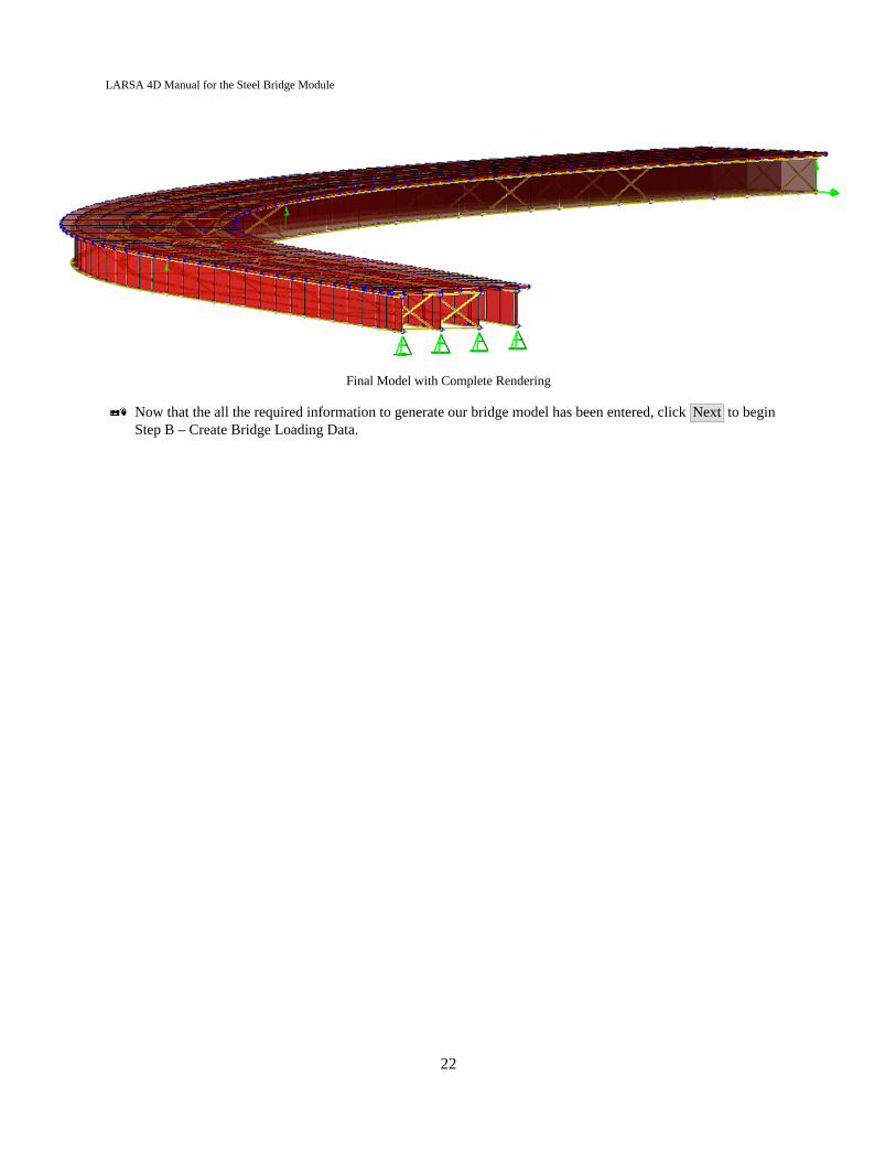
Final Model with Complete Rendering
Now that the all the required information to generate our bridge model has been entered, click Next to beginStep B – Create Bridge Loading Data.
22

LARSA 4D Manual for the Steel Bridge Module
Bridge Loading
For loading (Step B), the module generates load cases, staged construction information, and post analysis resultcases including linear result combinations, extreme effect groups (envelopes), and influence result cases accordingto AASHTO LRFD.
The information generated in this step is used by the Steel Bridge Module to perform staged analysis, and to designatethe proper code combination during code check.
We will now begin entering information for Step B - Create Bridge Loading Data.
Live Load
Live load parameters set options for the generation of influence surfaces for vertical, centrifugal, and braking forces.Live load acts on the composite section (girders and n slab).
Vehicular Longitudinal IncrementSets the influence coefficient grid spacing in the longitudinal (forward) direction.
Enter 10.0 ft for the Vehicular Longitudinal Increment.
For final models, use a smaller increment, typically between 1 and 3 ft. On a long bridge, a small increment willincrease the analysis time and disk space requirements significantly. Start with a large increment, such as 10 ft, toverify that input is correct. Then reduce the increment before a final code check.
Vehicular Transverse IncrementSets the influence coefficient grid spacing in the transverse direction.
Enter 6.0 ft for the Vehicular Transverse Increment.
For final models, use a smaller increment, typically 1 or 3 ft. On a long bridge, a small increment will increase theanalysis time and disk space requirements significantly. Start with a large increment, such as 6 ft, to verify that inputis correct. Then reduce the increment before a final code check. Enter 0 to have the program automatically choosea transverse spacing.
Centrifugal/Braking Longitudinal IncrementSets the influence coefficient grid spacing in the longitudinal (forward) direction for the centrifugal and brakinginfluence surfaces, or zero to omit centrifugal and braking force loading.
Enter 0.0 ft to discount the effects of centrifugal and braking forces.
Centrifugal/Braking Transverse IncrementSets the influence coefficient grid spacing in the transverse direction for the centrifugal and braking influencesurfaces. This option is not used when the corresponding longitudinal increment is zero. When a longitudinalspacing is given, you may enter 0 to have the program automatically choose a transverse spacing.
Enter 0.0 ft.
Centrifugal Design Velocity
23

LARSA 4D Manual for the Steel Bridge Module
Sets the design velocity in miles per hour used to compute the factor C (Eq. 3.6.3-1) applied to influencesurface results for centrifugal forces.
Enter 0.0 ft to discount the effect of centrifugal forces.
Sidewalk
The module defines the width of the sidewalks at each edge of the bridge. The module uses this information for theloading representing the non-structural thickness of the sidewalk. Sidewalk width also determines the distance of theroadway from the edges of the bridge.
Sidewalk Width + Barrier at +Y/-Y edgeSidewalk width can be specified at each side of the deck, or if the deck does not have any sidewalks enter 0.The sign follows the right-hand rule: -Y is on the side of girder 1, and +Y is on the side of the last girder.
Enter 1.0 ft. for the sidewalk width + barrier on each side.
Non-structural sidewalk thicknessThis is the thickness of the sidewalks, besides what is accounted for by the deck thickness. This thickness isused to apply extra dead load on the sidewalks, and can be ignored by entering zero for this loading.
Enter 0.0 kips/ft.
Miscellaneous Loads
StrengthStrength information defines general line loads for the utility on the bridge deck structure during construction.
Wind LoadWind load, which is available separately both for strength and constructability, will be applied to the girders inthe transverse direction. The module will apply the loads both in negative and positive directions and take theenvelope at the code check step.
Enter 0.0 kips/ft² for the wind load.
RailingsEnter the load for barrier, parapet or bridge rails. The magnitude of the load should be entered per linear lengthas the load is applied to the edges of the deck as uniform line load.
Enter 0.382 kips/ft for the railings.
PedestriansPedestrian load is applied to sidewalk surfaces and should be entered as load per unit area. It is combined andenveloped with the vehicular live load cases at the code check step.
Enter 0.0 kips/ft for pedestrians.
Future Wearing SurfacesAdditional permanent load can be applied to the roadway surfaces due to future wearing surfaces. Themagnitude of the load should be entered as load per unit area.
Enter 0.03 kips/ft for future wearing surfaces.
Monolithic Wearing Surfaces24
LARSA 4D Manual for the Steel Bridge Module
Additional permanent load can be applied to the roadway surfaces due to monolithic wearing surfaces. Themagnitude of the load should be entered as load per unit area.
Enter 0.0 kips/ft² for monolithic wearing surfaces.
Utility LoadsUtility loads can be specified by providing the start and end location and the magnitude. The start and endlocations are provided as station and offset pairs as reference to the bridge alignment. Utility loads are appliedas uniform line loads, so the magnitude should be entered as load per linear length.
Skip Utility Loads.
Construction Loads
Based on LARSA 4D’s staged analysis, define the information used for staged construction activities such as deckpouring sequence, screed movement, deck formwork weight, or to designate the incorporation of a staged analysisbetween stations.
Screed WeightThe weight of the screed (as applied to each edge of the deck). If this field is non-zero then screed movementwill be simulated in staged construction. If deck pouring sequence is not provided, then the screed will besimulated as moving from one end of the bridge to the other end with the screed movement increment provided.If a deck pouring sequence is provided then the screed movement is simulated conforming to the sequence.
Enter 0.0 kips for screed weight.
Skew Angle of the ScreedA skew angle in degrees should be provided if the screed is positioned at an angle (using the same directionrule as the pier skew or cross frame skew data).
Enter 0.0 deg.
Screed MovementThis field specifies the intervals of the screed movement and must be a positive nonzero value.
Enter 0.0 ft.
Screed Rail Position Relative to the Exterior GirderThis field determines the locations of the screed rails on either side of the bridge. It is the distance from theexterior girders to the rail. This field is always given as a positive value. The rails are always before the firstgirder and beyond the last girder of the bridge.
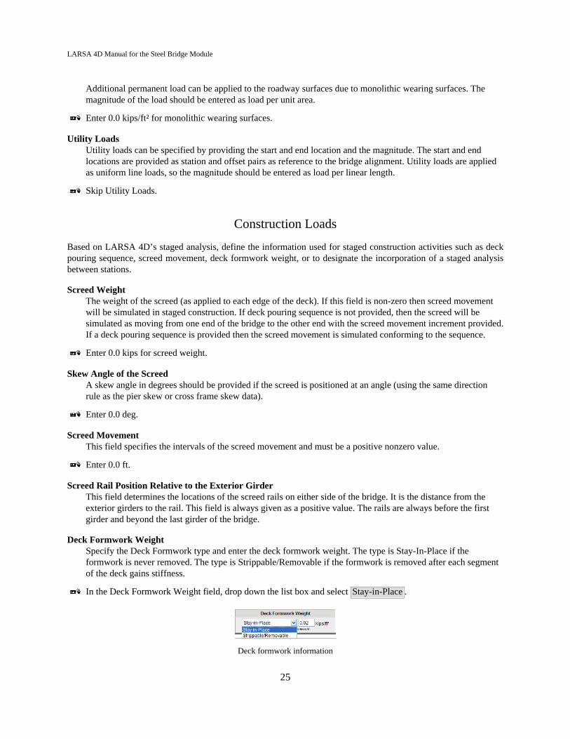
Deck Formwork WeightSpecify the Deck Formwork type and enter the deck formwork weight. The type is Stay-In-Place if theformwork is never removed. The type is Strippable/Removable if the formwork is removed after each segmentof the deck gains stiffness.
In the Deck Formwork Weight field, drop down the list box and select Stay-in-Place .
Deck formwork information
25
LARSA 4D Manual for the Steel Bridge Module
Enter 0.02 kips/ft² for the weight of the deck formwork.
Deck Pouring SequenceAllows the specification of the deck pouring sequence. The surfaces that are poured and their order can bespecified on this spreadsheet. Each pouring region is defined by giving a start and end station. The weight ofthe deck will be automatically calculated using the pouring region dimensions, the deck thickness, and theconcrete material property. If no deck pouring sequence is given, the entire deck is poured at once.
Deck Pouring Sequence TypeWith a deck pouring sequence, Composite at the End indicates only the deck weight is applied duringconstruction. Deck elements gain stiffness only after the whole deck is poured. Composite As Built indicatesthat each poured segment of the deck is constructed with weight and stiffness simultaneously.
Skip the Deck Pouring Sequence.
This is all the information module needs to create code based loading and staged construction data for the bridge.
Click Next to see the confirmation screen and click Next again to start the generating process.
LARSA 4D will now scan the model to make sure no manual changes in structure properties were entered betweenStep A and Step B.
Once the generation process starts, you will be asked a project file name and a parametric section database name, *.larand *.lpsx files respectively. *.lar file is for the project and *.lpsx file is used to store the custom section databasecontaining the sections used in the finite element model. It is a good practice to save all your files into the same folder.
The module will display a status windows and a progress bar. If the progress bar stops for a second or two, it does notmean that the process has stopped. You should be able to see the progress bar moving in five to ten seconds. If StepC (code check) was checked at the start, the code check options will be shown after the model has been generated.If code check is not being performed, then the module will exit and the generated model and loading can be usedwithin LARSA 4D.
26

LARSA 4D Manual for the Steel Bridge Module
Code Check for AASHTO LRFD
Having originally selected Step C in the beginning of this tutorial, the module automatically begins enteringinformation for Code Check per AASHTO LRFD on the specified locations.
Step C - Code Check
Click Next to begin the code check.
The module first scans the model to check for any changes in the structure before going into the design part. This maytake a minute or two based on the size of the structure and the refinement of the influence surface for live load.
Code Check on an Existing Model
While the model generation component of the Steel Plate Girder Bridge Module can be used to rapidly create a LARSA4D model, the module can also code check a model created independently or created by the module but modified bythe user before the code check process. In that case, have the model open in LARSA 4D before starting the moduleand do not check Step A. By not checking Step A, the module will scan the existing model.
Recognizing Geometry
In a code check of an existing model, the module must recognize what elements in the model are girders, which arecross-frames, which members make up each girder, etc. Such information is not explicit in a general finite-elementmodel and must be determined by the module automatically. Existing models to be used with the code check musttherefore look like the types of bridge models that the module can generate otherwise the module may fail to recognizethe organization of the model.
The module will ask several questions about the model to be recognized so that the module knows what kind of bridgeto look for in the model.
Groups, Loading, and Stages
The module can create structure groups, load cases, and construction stages for a model with existing geometry but forwhich these entries have not been created yet. This is necessary for running an analysis of the right code combinations,but they may be useful in your own investigations even if you are not running code check through the module.
The structure groups created represent the different components of the structure: cross-frames, girders, and the deck.The construction stages define a common order of assembly of the bridge. The user is free to modify these entriesafter they are created.
27
LARSA 4D Manual for the Steel Bridge Module
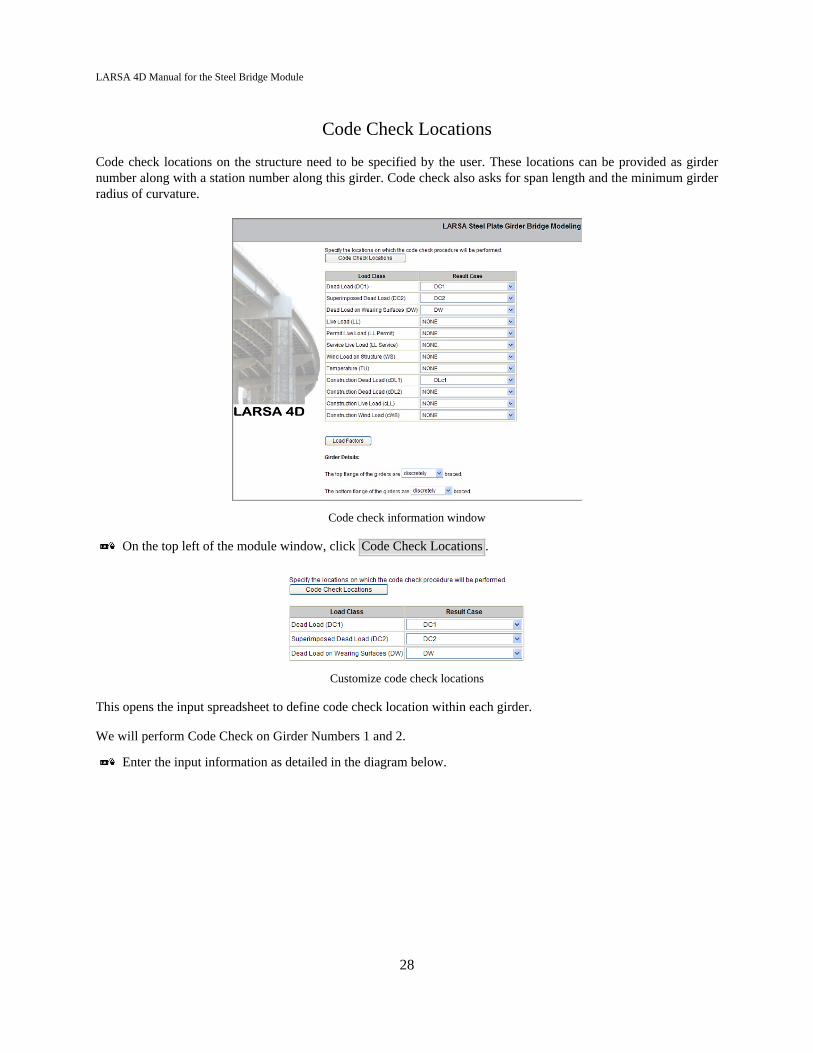
Code Check Locations
Code check locations on the structure need to be specified by the user. These locations can be provided as girdernumber along with a station number along this girder. Code check also asks for span length and the minimum girderradius of curvature.
Code check information window
On the top left of the module window, click Code Check Locations .
Customize code check locations
This opens the input spreadsheet to define code check location within each girder.
We will perform Code Check on Girder Numbers 1 and 2.
Enter the input information as detailed in the diagram below.
28

LARSA 4D Manual for the Steel Bridge Module
Code check location information
Three additional tabs (Deck Reinforcing, Transverse Stiffeners, and Longitudinal Stiffeners) open spreadsheets tocontrol additional code check parameters at each code check location.
Fill out the parameters on the remaining three tabs as necessary.
Click Back to Main Page .
Load Cases
As the model is scanned, it recognizes that certain stages are not entered, and created additional result cases. Cases areautomatically created for you which we can see in DC1 which created an envelope under live load results in AASTHO,based on the deck pouring sequence which we previously specified.
In the Code Check step (Step C), the module will automatically select appropriate result cases for you. You can modify/add new design cases in LARSA 4D and then use these cases as design cases on this screen.
The design cases are combined with certain factors based on the AASHTO LRFD code, and factors can be viewedand modified.
To custom define the result case of a load class, click the drop down which presents a list of the load casesgenerated within the module.
29

LARSA 4D Manual for the Steel Bridge Module
Customizing the result case of a load case
Cases are automatically created for dead load results from DC1 to create an envelope under Live Load results inAASHTO, based on the deck pouring sequence which was previously specified.
Girder Details
In the top flange field, drop down the list box, and designate the top flange girders as Continuously Braced.
In the bottom flange field, drop down the list box, and designate the bottom flanges of the girder as DiscretelyBraced.
Running Code Check
Now that the desired cases, code check locations girder details are defined, click Next to begin the CodeCheck process.
Each specified location on the structure is code checked independently for both negative and positive effects.
Once the Code check completes, the Code Check Summary Report will automatically open.
30

LARSA 4D Manual for the Steel Bridge Module
Code check summary report
This report is designed to provide the required code check information in one sheet, and reports girder properties fortop and bottom flanges, deck properties, haunch and reinforcing, followed by a second set of properties for short andlong term composite properties for each girder at the specified locations.
Reports
To go a step further than the summary report for each section, click the specific girder location on the top leftof the screen to report the detailed results.
Code check girder locations
To view the line-by-line computations in the detailed report, MathPlayer software is required. The program can bedonwlaoded and installed using the provided link.
MathPlayer download prompt
31
LARSA 4D Manual for the Steel Bridge Module
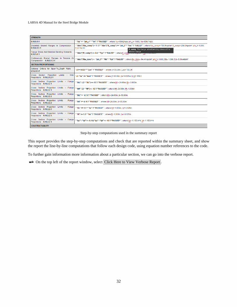
Step-by-step computations used in the summary report
This report provides the step-by-step computations and check that are reported within the summary sheet, and showthe report the line-by-line computations that follow each design code, using equation number references to the code.
To further gain information more information about a particular section, we can go into the verbose report.
On the top left of the report window, select Click Here to View Verbose Report .
32

LARSA 4D Manual for the Steel Bridge Module
Verbose report
This spreadsheet tells us the mapping, reporting each result and its location, allong with where LARSA extractedresults from. The report includes the positive and negative forces at the code check location based on Live Load resultsbased on the Loading Information entered at the beginning of this tutorial. The module uses compound total compositegirder in order to take all elements into account, and slice the girder at the specified location to figure the compositeforces and moments in either the girder alone, or in the composite girder.
The first section of this report includes results for Live Load cases DC1, DC2, DW, LL and DLc1, followed by Forcesand Moments.
Further detail result reports in Verbose including slab width, section properties, flange stresses for strength etc.
Detailed reports are displayed with the default Internet web browser of the computer so that the report is easilynavigable and easy to read (although the report is stored on your computer and no Internet connection is necessary orused). In order to see the formulas properly, we recommend using the Mozilla Firefox web browser and setting it asthe computer’s default web browser. Microsoft Internet Explorer version 6 or newer is also supported but additionalsoftware called MathPlayer must be downloaded and installed from http://www.dessci.com/en/products/mathplayer/.At the time of writing, the Opera, Chrome, and Safari web browsers are not supported because they lack support forMathML.
Code Check Additional Parameters
The following information is needed to perform code-check on the structure:
PedestriansThere are pedestrians or no pedestrians on the bridge.
Non-Composite Result Case
33
LARSA 4D Manual for the Steel Bridge Module
The result case without the effects of the deck.
Superimposed Dead Load CaseThe result case with the effect of superimposed dead load.
Superimposed Live Load CaseThe result case with the live load effects.
Final CaseThe final staged construction result case.
ArtArea of the top layer of longitudinal reinforcement PER FOOT of concrete deck width
ArbArea of the bottom layer of longitudinal reinforcement PER FOOT of concrete deck width.
FyrsYield strength of the longitudinal reinforcement of the concrete.
CrbDistance from the top of the concrete deck to the centerline of the bottom layer of longitudinal concrete deckreinforcement.
CrtDistance from the top of the concrete deck to the centerline of the top layer of longitudinal concrete deckreinforcement.
AntoAgRatioThe ratio of net area to gross area of the tension flange .
Bracing at Top FlangeThe top flange of the girders are discretely continuously braced.
Bracing at Bottom FlangeThe bottom flange of the girders are discretely continuously braced.
LbThe distance between intermediate diaphragms or cross frames (unbraced length - 'Lb') .
CbThe moment gradiant modifier (Cb).
StiffenersAre there any stiffeners on the structure.
Stiffener MaterialThe material of the flange stiffneres used on the structure.
do2The smaller of the adjacent web panel widths is (used for transverse stiffener check, see 6.10.11.1.3-3).
dlongDistance of longitudinal stiffener from top of the girder (VERTICAL distance for box girders).
34

LARSA 4D Manual for the Steel Bridge Module
blThe projecting width of longitudinal stiffeners.
tlThe thickness of longitudinal stiffener.
Longitudinal Stiffener DirectionSpecify if the longitudinal stiffeners facing center of curvature
do1Transverse stiffener spacing in the interior panels (not bearing stiffener spacing).
Stiffener position densitySpecify if there are any transverse stiffeners within D/2 on EACH side of the interior-pier sections. (iftransverse stiffeners are present at the limit of D/2 from the interior pier, this is considered TRUE)
btProjecting width of transverse stiffeners.
tpThe thickness of transverse stiffeners.
Location of Transverse StiffenersTransverse stiffeners are on one side or two sides of the girders.
bbThe projecting width of bearing stiffeners.
tbThe thickness of bearing stiffeners.
Location of Bearing StiffenersBearing stiffeners are on one side or two sides of the girders. They are welded or not to the web.
kkDistance from the outer face of the flange resisting the concentrated load or bearing reaction to the web toe ofthe fillet.
NNLength of the bearing.
Location of the Bearing ReactionThe bearing reaction of concern is at the interior or exterior part of the girder.
Location of the Reaction or Concentrated LoadIs the reaction or concentrated load applied at a distance from the end of the girder that is greater than the fulldepth of the girder?
blfThe projecting width of bearing stiffeners.
tlfThe thickness of bearing stiffeners.
w
35

LARSA 4D Manual for the Steel Bridge Module
Larger of the width of the flange between longitudinal flange stiffeners or the distance from a web to thenearest longitudinal flange stiffener.
nNumber of equally spaced longitudinal flange stiffeners in the compression box flange.
d_tflangeLongitudinal distance between transverse flange stiffeners.
36
LARSA 4D Manual for the Steel Bridge Module
Index
AASHTO LRFD code check, 27abutments, 11bearing, 11box girder, 15bridge alignment/layout, 11bridge path coordinate systems, 11center line, 11code check, 27cross frames, 15deck, 21deck formation weight, 23deck plate refinement, 21deck pouring sequence, 23future wearing surface, 23girders, 15haunch thickness, 15heading, 11I girder, 15influence surface options (Steel Bridge Module), 23joint location tolerance, 21live load, 23load factors (code check), 27loads (Steel Bridge Module), 23material (cross frames), 15material (deck), 21material (girders), 15monolithic wearing surface, 23node location tolerance, 21overhang, 21pedestrians, 23piers, 11plate girder, 15pouring sequence, 23refinement, 21reports (code check), 27screed, 23section dimensions, 15sidewalk, 23skew, 11splice points, 15station
Bridge Alignment and Piers, 11Girders, Cross Frames, and Splice Points, 15
Steel Bridge Module, 7supports, 11transverse offset, 15tub girder, 15utility loads, 23wind load, 23
37