Embed Size (px)
Citation preview
Mechanical Engineering: An International Journal ( MEIJ), Vol. 1, No. 2, August 2014
27
A METHODOLOGY FOR ANALYSIS OF
TOPOLOGICAL CHARATERISTICS OF
PLANETARY GEAR TRAINS
Dr. S.R.madan, Sajid Quresh, Mustaq Ptel
Mahakal Institute of Technology and Management, UJJIN, (M.P.), India.
ABSTRACT:-
A planetary trains for multi-speed is mainly used for automation in industries of automobile. A planetary
gear train is represented by a graph. It is identified by (i) number of vertices and their connectivity (ii)
number of edges and their types and values (iii) fundamental circuits, their size and adjancy. Connectivity
of individual link is a property characteristic of kinematic chain. It is possible to identify a planetary gear,
therefore of using sets of labele (decimal numbers representing connectivity ) of individual link. The
connectivity of vertices , edges values and circuit values, related to design invariants which in turn
indicates the possible behavior of the gear train ( for example capacity of power transmission, speed ratio
and power carculation). For a specified degree – of – freedom a number of planetary gear kinematic chain
(PGKCs) are selected and hence planetary gear trains (PGTs) can be formed with a given number of links
and joints so that designer must be able to select to select the best train from the view point of say velocity
ratio and capacity of power transmission, space requirements etc. Synthesis of planetary gear kinematic
chain and planetary gear trains has been studied(1-9).
Almost all reported work deals with only
identification of distinct chains. Besides providing an atlus of chains, this in itself does not provide any help
to designer in the selection of best possible gear train. In the present paper a simple method based of
circuit property ( based on link-link shortest path distance and degree of links) is presented to determine
the topology values of power transmission efficiency and topology power transmission capacity of five-links
PGKCs and their distinct inversions.
KEYWORDS:-
Graph theory. Information theory, Isomorphism, Distinct inversions, Planetary gear trains.
1. INTRODUCTION:- Many investigators have studied synthesis of planetary gear kinematic chains and planetary gear
trains in detail[1-9,11]
. Almost all reported the work based on identification of distinct chains and not
much beyond these. Beside providing an atlas of chains, this in itself does not provide any help to
designer in selection of best possible gear train.
There is always necessity of more information in this respect regarding ability of PGKCS (Planetary
Gear Kinematic Chains) to a designer, to helps in taking his choice. The structure of a chain alone

Mechanical Engineering: An International Journal ( MEIJ), Vol. 1, No. 2, August 2014
28
is not capable of revealing its actual performance as the dimensions of machine elements also are
considered to influence it. The structure, however can be used to reveal certain characteristics- like
the inherent ability to generate greater velocity ratio, loss of motion and power in a comparative
sense. In the present paper, a simple numerical method ( based on link-link shorest path distance
and degree of links) is proposed to relate the topology of chain to provide the idea of corresponding
loss of motion and power with identification code. Also proposed method is tried to use the rated
comparison of all the distinct five-links PGKCs and their distinct inversions.
2. GRAPH REPRESENTATION:- Graph Theory has been used extensively for topographical study of plannar kinematic chains.
Following the approach of graph theory, each element in the gear train is represented by a vertex
and each join by an edge of a graph. For example, Fig.-1(a) shows a simple gear train in which the
arm is fixed and the wheels are free to rotate about their respective axis. And Fig.-1(b) shows the
simplest planetary gear train in which the wheel is fixed, and arm being free. For topological
studies, the size of the wheel and manner of meshing i:e internal or external, are immaterial. Both
the gear trains of Fig.1 are represented by graph, Fig.-1(c) , in which the gear pair between wheel 1
and 2 represented by a thick edge(line) while the revolute pair between the element 3 and wheel 1
and 2 are represented by thin edge. Beside satisfying many algebraic requirements such as the
relationship between the number of edges and vertices etc., a planetary gear train, which
represented by a graph needs additional information such as the level of edge. Rotating graph[6,8,9]
of
PKGS has been extensively used for the topological study but its inadequacies have lead to its
modification and one can finally accept of representation of PKGC by the coincident joint graph[8]
.
Details of development of coincident- joint graph are dealt with elsewhere[8]
, and are not repeated
here as purpose of the paper is only to reveal some important properties of the resulting trains.
3. TYPE OF JOINTS, EDGES AND THEIR NUMBER:- Every edge in a graph represents either a turning pair or gear pair. The role of an edge between a
turning pair or gear pair is significant. The role of edge between two vertices in a graph (relation to
graph as a whole) is signified by a number and type of other edge to which it is connected. So
contribution of every edge in a graphis quantifies by a number values, which is the sum of
numerical values of all other edges that are connected to it. The sum is called joint or edge values.
The edge value is related to vertex conntevity in the following manners.
The edge(ij), that is topological edge connectivity can be expressed as

Mechanical Engineering: An International Journal ( MEIJ), Vol. 1, No. 2, August 2014
29
Topological connectivity of vertex i + Topological connectivity of vertex j – 2× Topological value
of eij ----------------------------------------------(1)
4. ARCHITECT OF THE PROPOSED METHOD:-
Labeling of link (Vi) –
Usually, the canonical labels depend only on the connectivity of the links being labeled together
with its immediate neighbours. However, in a closed kinematic chain, links are connected by
joints so as to form loops and every link has a distinct relation with every other link in the form of
distance between them which is constant and presented here by a matrix is called link path matrix
of the chain. Bearing this in mind the usual canonical labeling is extended to include all links of
the chain. Canonical label V of a link of a kinematic chain, defined here, is a sum of path
weighted connectivity of the links. Each link L is assigned a label Vi as follows –
-----------------(2)
Where Wj is the weight of degree of j
th link with related to total
degree of kinematic chain . And
Wj is related weight of degree of the links which is defined as the ratio between of jth link and
total degree of kinematic chain given as
Wj =d(Li) / d(KC) -------------------------(3)
To include all links but give a higher path weight to those closest to the link Li being labeled, a
factor of ( ½ Dij
) is included where, Dij is the distance between the links Li and Lj. This distance is
defined as the shortest path between any two links of a chain. N is the total number of links in the
chain being labeled.
And link degree = 1 if vertices i and j are connected by a revolute joint
Link degree = 2 if vertices i and j are connected by a gear pair ( by thick edge).
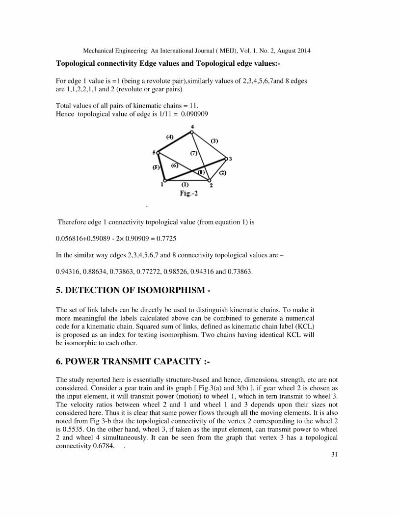
For example 1 for the graph of five element PGT [Planetary Gear train)(shown in Fig.-2)
Value of connectivity of vertex 1 = gear pair + gear pair + revolute pair
= 2+2+1 = 5
Similarly values of vertex 2,3,4and 5 are 4,4,4 and 5.
So complete values of kinematic chain = 5+4+4+4+5 = 22
Hence topological connectivity value of vertex 1 ( or weight Wj) = 5/22 = 0.22727
Similarly topological connectivity values of all vertices i:e 2,3,4 and 5 are 0.1818, 0.1818, 0.1818
and 0.22727.
Mechanical Engineering: An International Journal ( MEIJ), Vol. 1, No. 2, August 2014
30
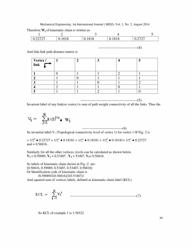
Therefore Wj of kinematic chain is written as-
1 2 3 4 5
0.22727 0.1818 0.1818 0.1818 0.2727
-------------------------------(4) And link-link path distance matrix is
Vertex /
link
1 2 3 4 5
1 0 1 1 2 1
2 1 0 1 1 1
3 1 1 0 1 2
4 2 1 1 0 1
5 1 1 2 1 0
---------------------------------------------(5) Invarient label of any link(or vertex) is sum of path weight connectivity of all the links. Thus the
-----------------------------------(6)
So invarient label V1 (Topological connectivity level of vertex 1) for vertex 1 0f Fig. 2 is
= 1/20 ● 0.22727 + 1/2
1 ● 0.18181 + 1/2
1 ● 0.18181 + 1/2
2 ● 0.18181+ 1/2
1 ● 0.22727
and = 0.56816.
Similarly for all the other vertices, levels can be calculated as shown below.
V2 = 0.59089, V3 = 0.53407 , V4 = 53407, V5= 0.56816.
So labels of kinematic chain shown in Fig.-2 are-
[0.56816, 0.59089, 0.53407, 0.53407, 0.56816]
Or Identification code of kinematic chain is
/0.59089/2(0.56816)/2(0.53407)/
And squared sum of vertices labels, defined as kinematic chain label (KCL)
-----------------------------------------------------( 7)
So KCL of example 1 is 1.56522
Mechanical Engineering: An International Journal ( MEIJ), Vol. 1, No. 2, August 2014
31
Topological connectivity Edge values and Topological edge values:-
For edge 1 value is =1 (being a revolute pair),similarly values of 2,3,4,5,6,7and 8 edges
are 1,1,2,2,1,1 and 2 (revolute or gear pairs)
Total values of all pairs of kinematic chains = 11.
Hence topological value of edge is 1/11 = 0.090909
.
Therefore edge 1 connectivity topological value (from equation 1) is
0.056816+0.59089 - 2× 0.90909 = 0.7725
In the similar way edges 2,3,4,5,6,7 and 8 connectivity topological values are –
0.94316, 0.88634, 0.73863, 0.77272, 0.98526, 0.94316 and 0.73863.
5. DETECTION OF ISOMORPHISM -
The set of link labels can be directly be used to distinguish kinematic chains. To make it
more meaningful the labels calculated above can be combined to generate a numerical
code for a kinematic chain. Squared sum of links, defined as kinematic chain label (KCL)
is proposed as an index for testing isomorphism. Two chains having identical KCL will
be isomorphic to each other.
6. POWER TRANSMIT CAPACITY :- The study reported here is essentially structure-based and hence, dimensions, strength, etc are not
considered. Consider a gear train and its graph [ Fig.3(a) and 3(b) ], if gear wheel 2 is chosen as
the input element, it will transmit power (motion) to wheel 1, which in tern transmit to wheel 3.
The velocity ratios between wheel 2 and 1 and wheel 1 and 3 depends upon their sizes not
considered here. Thus it is clear that same power flows through all the moving elements. It is also
noted from Fig 3-b that the topological connectivity of the vertex 2 corresponding to the wheel 2
is 0.5535. On the other hand, wheel 3, if taken as the input element, can transmit power to wheel
2 and wheel 4 simultaneously. It can be seen from the graph that vertex 3 has a topological
connectivity 0.6784. .

Mechanical Engineering: An International Journal ( MEIJ), Vol. 1, No. 2, August 2014
32
It can thus be generalized saying that vertex with higher topological gear connectivity can
transmit more power. It is, therefore obvious that a gear train with greater connectivity (that is
sum of the connectivity of all the vertices of its graph) can transmit more power. The problem,
however, arises when comparison has to be made between the gear trains with the number of
elements and degree of freedom, which have equal connectivity.
For example, consider graphs of two distinct gear trains [ Fig. 4(a) and Fig. 4 (b)] with four
elements. The total connectivity of all vertices in both the gear is equal to 14, but the distribution
of topological connectivity among vertices is not same, in case of Fig. 4 (a) the distribution
among vertices 1,2,3 and 4 are respectively 0.6071, 0.5535, 0.678, 0.5535 , KCL is 2.39 and sum
of topological connectivity 2.457while in Fig. 4 (b) it are 0.6428, 0.6428, 0.5535, 0.5535, KCL is
2.39 and sum of topological connectivity is 2.3926. So it is clear that the capacity of an element
(vertex) to transmit power depends upon its topological connectivity value. Since the graph ( that
gear trains) consists of vertices with different connectivities, it is necessary to know which of the
combinations or distribution, with the same structural connectivity will lead to greater capacity to
transmit power. Hence, a numerical measure becomes necessary to compare such graph of trains
and same is proposed in later section.
7. TRANSMISSION EFFICIENCY :- Efficiency or loss of power is associated with every joint (that is, edge) and quantum of power
transmission as will its loss depends upon the type of the joint. Two gear trains with the same
vertex assortment can behave differently in, performance wise due to difference in edge values. It
will be evident from the rules of graph formation for a gear train that the number of edges and
Mechanical Engineering: An International Journal ( MEIJ), Vol. 1, No. 2, August 2014
33
their type will remain the same for all the gear trains with the same number of elements and
degree-of-freedom. For example in Fig 4 (a) and Fig. 4 (b) the edge are numbered (1), (2), -----
etc and their values are respectively 0.8746, 0.9991, 0.8746, 0.6595 and 0.6595 while for Fig.
4 (b) they are respectively 0.91, 0.9996, 0.91, 0.624 and 0.624 (from equation 1).Transmission
efficiency or the loss of energy at a joint depends upon the number of other joints it is directly
connected to. In fact the edge values is related to number of design parameters involved by
equation (1) and hence to the efficiency of power transmission. Thus the distribution of edge
values influences the transmission efficiency, while the edge value of graph is indicative of power
loss. A numerical measure for comparing the transmission efficiency of distinct gear trains is
proposed later.
8. NUMERICAL MEASURE :- In the earlier section, factors influencing (i) power transmission, and (ii) transmission efficiency,
have been dealt with. In this section, formulae to estimate circulation are developed.
(a) CAPACITY :- It has been stated in the earlier section that topological connectivity of a vertex (element) is
related to a number of design parameters. It also proved through the example of the train (that is
for Fig. 3) that an element with greater topological connectivity can transmit more power.
Obviously, it also means that an element with lesser topological connectivity will transmit less
power. Since, the gear train is a combination of element with different topological connectivities,
its capacity to transmit maximum power is limited by element (vertex) with least connectivity. It
is, therefore evident vthat a train can transmit maximum power when all its element are of equal
connectivity, which in reality may not be possible. Hence, a relative estimate becomes necessary.
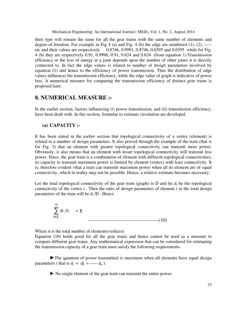
Let the total topological connectivity of the gear train (graph) is D and let di be the topological
connectivity of the vertex i . Then the ratio of design parameters of element i to the total design
parameters of the train will be di /D . Hence
-------------------------------------------(10)
Where n is the total number of elements(vertices)
Equation (10) holds good for all the gear trains and hence cannot be used as a measure to
compare different gear trains. Any mathematical expression that can be considered for estimating
the transmission capacity of a gear train must satisfy the following requirements-
►The quantum of power transmitted is maximum when all elements have equal design
parameters ( that is di = dj = ----- dn ).
► No single element of the gear train can transmit the entire power.

Mechanical Engineering: An International Journal ( MEIJ), Vol. 1, No. 2, August 2014
34
►The quantum of power transmitted by a fixed link is zero.
A mathematical equation that satisfies the above requirements is expressed as
Pi log Pi ----------------------(11)
Where Pi = di / D
It is chosen in such a way that 1 log 1 = 0 and 0 log 0 = 1, in order to satisfy the above mentioned
requirements ( especially the last two conditions).
Then the topological power transmitting capacity P of the gear train is expressed as
-----------------(12)
It may be noted that equations satisfies all requirements. Equation (11) has strong
resemblance to the expressions for entropy commonly used in information theory, while equation
(12) resemblance to the condition that sum of the probabilities of various events is equal to one.
It is therefore, evident that by proper interpretation the concepts developed in Information
Theory can be applied to kinematic chains and gear trains. The above concept is illustrated by the
following problem.
(b) EXAMPLE :- Consider the two trains and their graph(Figure 5 (a) and Fig. 5 (b). Gear
trains are compared for their ability to transmit power. For the gear trains, the
connectivity of the vertices (element) can be obtained directly from their graphs. For the
train [Figure 5 (a)], the topological connectivity values for the vertices 1,2, ----6 are
respectively 0.6347, 0.4231,0.5579,0.4231,0.5289 and 0.5289 therefore the total
topological connectivity is 3.096 . Using equation (10), (11) and (12), one can write

Mechanical Engineering: An International Journal ( MEIJ), Vol. 1, No. 2, August 2014
35
Figure-5
For the gear train [ shown in Fig.5(b)] the connectivity of the vertices 1,2,---6 are respectively
0.5960, 0.4037, 0.5960, 0.4037,0.5207 and 0.5287. The sum of connectivity is 3.0570. Using
equations (10),(11) and (12) one gets-
On comparison of P values it is found the train shown by Fig. 5 (a) has greater capacity to
transmit power.

Mechanical Engineering: An International Journal ( MEIJ), Vol. 1, No. 2, August 2014
36
( c) TRANSMISSION EFFICIENCY :-
Using equation (1), the numerical value of all edges of a graph can be determined. Let Ji, be the
edge value with ith edge. Then, the edge value of the graph or train can be represented as-
-----------------------------------(13)
Where k is the total number of edges in the graph.
The ratio of edge value of the edge I to edge value of the graph is Ji / J
Hence
---------------------(14)
Equation (13) holds good for all the gear trains and hence cannot be used as a compare to
different gear trains. Any mathematical expression that can be considered for estimating the
transmission efficiency must satisfy the following requirement
■ Energy transmitted is maximum when all the edges / joints are of equal value.
■ No single joint of a gear train will transmit the entire edge value.
■ Fixed elements, if any, in a joint will not contribute to the edge value.
A mathematical expression that satisfies the requirements (especially the second and
third are as mentioned below)
------------------------------------------------(15)
The expression has all the traits of the earlier expression (11). Therefore, the energy transfer E
through all the joins of a gear train can be expressed as
----------------------------------------------------(16)

Mechanical Engineering: An International Journal ( MEIJ), Vol. 1, No. 2, August 2014
37
The expression (16) assume a maximum or ideal value Em when J1 = J2 ---- Jk; which satisfies the
first of the above three requirements. Equations (14) and (16) are analogous, once again to the
equation of entropy in the Information Theory.
The topological transmission efficiency is defined as the ratio of the actual topological energy (E)
to the maximum topological energy Em.
The transmission efficiency (Te) of a gear train can be expressed as:-
------------------------------------------------------------(17)
For illustration, the two gear trains along with their graphs [Figure 5(a) and Figure 5(b)] are
considered.
For the graphs [shown in Fig. 5 (a)], the topological edge values are 0.904, 1.0385, 0.904, 0.7982,
0.7982, 0.856, 0.7792, 0.7792 and 0.856. .
The total topological edge value is 7.7133 .
Hence-
And
Then using equation (17), one gets topological efficiency = Te = 0.95194/1.0348 = 0.9199
For gear train [Fig.5(b) , the topological edge values are 0.8091, 1.0382, 0.8459, 0.8171, 0.7786,
0.8171, 0.8091, 0.8459 and 0.7708
The total Topological edge value is 7.5318
Then
And
By using equation (17), the topological transmission efficiency becomes = 0.9088.
The comparison of topological efficiency shows that the gear train [ that is Figure 3(a)]is better.
Identification code, KCL, Topological power transmission and Topological efficiency of all the five
elements PGKCs (shown by Figure) are given in table-1.

Mechanical Engineering: An International Journal ( MEIJ), Vol. 1, No. 2, August 2014
38
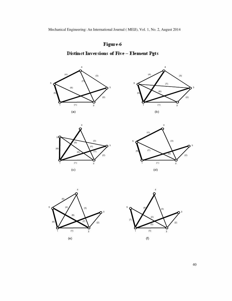
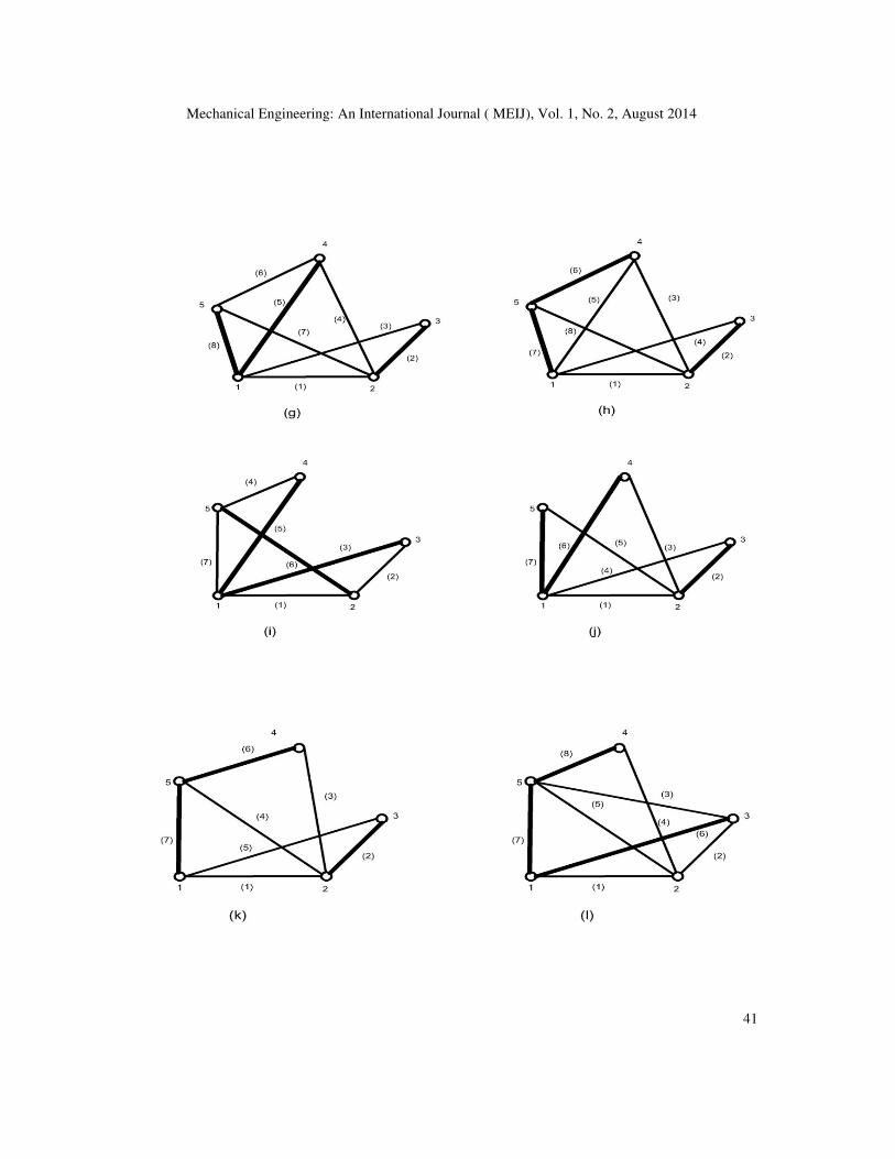
Table-1:- Rating of all Distinct Inversion of Five-Element PGTs ( shown in Fig. -6)
S.No Identification code of PGKs shown by
Figure-6
KCL Topological
Capacity of
transmission
of power
Topological
efficiency
A /0.59083/2(0.56816)/2(0.53407)/ 1.5652 0.69863 0.93005
B /0.64582/2(0.60415)/0.55207/0.52082/ 1.72313 0.69774 0.9669
C /0.65907/0.59089/2(0.556801/0.47726/ 1.63136 0.69663 0.94692
D /0.50750/2(0/0.600/0.58750.4750)/ 1.50156 0.69652 0.89564
E /0.63635/2(0.61362)/2(0.53408)/ 1.72849 0.69776 0.96664
F /0.6750/0.6000/3(0.5000)/ 1.56562 0.69547 0.97826
G /0.63634/0.61362/2(0.55680/0.47726/ 1.62020 0.69688 0.94824
H /2(0.61362)/0.57953/0.55680/0.4659 1.61602 0.69688 0.95094
I /0.65/2(0.5625)/2(0.4875)/ 1.53062 0.6964 0.93266
J /0.650/0.6250/3(5.000)/ 1.5631 0.69577 0.93308
K /0.6250/0.5875/0.5625/0.4875/0.4750/ 1.5154 0.69654 0.91694
L /0.55/0.63635/0.59089/0.57953680/0.46599/ 1.61702 0.69675 0.94794
CONCLUSION:-
(1) In order to emphasize clarity showing gears in trains with working figures, gear train can be
represented by a graph.
(2) Comfortable suggestion is submitted to show gear trains by graphs which each graph
constituent will reveal the anticipated behavior of the gear train. Vertices and their
subsequent connectivity will indicate the topological capacity of power transmission. Edges
and their values will eventually reveal the topological efficiency of transmission, such
indicative arrangement will be beneficially as analogous for comparing two gear trains
developing different powers with different efficiencies.
(3) As regards clarity of the suggested numerical measures taken for having strong resemblance
to properties and equations commonly used in Information Theory , there is every possibility

Mechanical Engineering: An International Journal ( MEIJ), Vol. 1, No. 2, August 2014
39
for other properties developed therein. So the Information Theory may be used with proper
interpretation for the study of linkages used in gear trains etc.
(4) Example problems [shown by figure 5(a) and figure5(b) ] are in fact pseudo isomorphic and
are deliberately chosen for illustration {that is, their characteristics being different, the better
one [Figure.5(a) can be retained the further generation of chains}.
(5) Table-1 shows the rating of all distinct (shown by figure 6) inversions of five element pgts.
REFERENCES:-
[1] F.Buchsbaum and F.Freudenstein “Synthesis of Kinematic Structure of Geared Kinematic chains and
other Mechanisms”, Journal of Mechanisms and Machine Theory, vol. 5, 1970,pp.357-392.
[2] FRE Crossley “ The Permutations of kinematic Chains of Eight Members of Less from graph,
Theoretic View Point”, Developments on Theoretical and Applied Mechanics, vol. 2, Pergamon Press
1965.
[3] L.Doberjanky and F.Freudenstein, “Some Application of Graph Theory to the Structural Analysis of
Mechanism”, A S M E. Journal of Engineering for Industry, vol. 89, 1967, pp. 153-158.
[4] F.Freudenstein “An Application of Boolean Algebra to the Motion of Epicyclic Drives”, A S M
E.Journalof Engineering for Industry, vol. 93, 1971, pp. 176-182.
[5] M. Haung and A.H.Soni “ Application of Linear and Nonlinear Graph in Structural Synthesis of
Kinematic Chains”, A S M E. Journal of Engineering for Industry, vol. 95, 1973, pp. 525-532.
[6] R. Ravishankar and T.S Mruthunjaya “ Computerized Synthesis of Structure of Geared Kinematic
Chains”, Mechanisms and Machine Theory, vol.27, no.5, 1985, pp. 367-387.
[7] H.Mayourian and F.Freudenstein “ The Development of an Atlas of Kinematic Structure of
Mechanisms”, Journal of Mechanisms Transmissions, and Automation in Design, vol..106, 1984, pp.
458-461.
[8] D.G.Olson, A.G.Erdman and D.R.Rileg, “Topological Analysis of Single-Degree-Freedom Planetary
Gear Trains”, A S M E Journal of Mechanical Design, vol. 113, 1991, pp.10-16.
[9] T.Lung-Wen “An Application of the Linkage Characteristic Polynomial to the Topological Synthesis
of Epicyclic Gear Trains’, A S M E Journal of Mechanisms, Transmission and Automation in Design,
vol.109, 1987, pp. 329-336.
[10] S.R.Madan and Sajjid Quershi “A New Theory (Based on invariant Labelling of Links) for
Topological Structural Analysis of Kinematic Chains”, International Journal of Research in
Aeronautical Mechanical Engineering, vol.2, Issue-2, Feb. 2014, pp.75-87.
[11] A.C.Rao”Topological Characteristic of Planetary Gear Trains”, Journal of Institution of Engineers
(India), vol. 77, May 1996, pp.7-12.
Mechanical Engineering: An International Journal ( MEIJ), Vol. 1, No. 2, August 2014
40
Mechanical Engineering: An International Journal ( MEIJ), Vol. 1, No. 2, August 2014
41