Embed Size (px)
Citation preview
A LECTURE ON CURRENT LIMITER
S. C. Mukhopadhyay
School of Engineering and Advanced Technology
Massey University, Private bag 11 222
Palmerston North, New Zealand
Emails: [email protected]
Submitted: Accepted: Published:
Abstract- A lecture on current limiter intended specifically for engineering students pursuing
specialization with Electrical and Electronics engineering is proposed in this paper. The important
information which doesn’t appear in text books are presented to the students. A general overview of
different techniques of limiting fault current in electric power systems with special emphasis on two
types of current limiters based on passive magnetic materials and high temperature superconducting
materials have been presented. Simple laboratory experiments are also proposed to validate the
theoretical knowledge.
Index terms: Power system, fault current, current limiter, permanent magnet, saturable core, magnetic
current limiter, high temperature superconducting fault current limiter.
I. INTRODUCTION
Almost in every field of modern civilization there is the requirement of electrical energy which
has resulted in a considerable increase of electrical power consumption. To meet the demand of
large electrical energy, the size of the power generating stations has become large. In many cases
a few generating stations are connected among themselves by interconnected networks
(powergrids), making the utility systems extremely large. Usually the consumption area of
electrical power is very wide, the chances of any kind of unforeseen accident, fault or abnormal
condition is very common. Somewhere in a power utility network, an unforeseen accident creates
a short circuit. The long transmission lines are bare and nakedly exposed to atmosphere.
Lightning may have struck a part of the system or the wind may have blown down an electric
pole and grounded the wires. Alternatively, a fallen tree limb, flyaway metallic balloon or unwary
squirrel may have been the cause of the failure. The blackout of Aug. 14, 2003 in USA was
caused by a cascading failure – a succession of transmission and generation outages, one
precipitating another – that spread through Northern Ohio, much of Michigan, Ontario, and New
York, as well as parts of Pennsylvania. While measures can be taken to reduce the number of
large-scale power losses due to failure of the generation and high-voltage transmission grid, such
failures cannot be eliminated [1]. One suggestion which was put forward is to go for increased
use of distributed generation (DG) which involves placing smaller generation sources closer to
the loads [2]. But even with DG based system possibility of occurring fault do exist.
The sudden reduction of the impedance of the power utility network will lead to an increase in
current, termed a fault current. That is, any of these mishaps at once sends a large current surging
through the various parts of power grids, causing a voltage reduction.
Moreover, the increase of electric power consumption has necessitated an increase in the system
fault current levels which has led to the following problems: power semiconductors in the power
system applications must be rated to accommodate the larger fault current levels. Larger
mechanical forces generated by the larger fault currents endanger the mechanical integrity of
power system hardware, transformer and other equipment may overheat. To avoid all these
difficulties, the system planner is then faced with the following alternatives:
(1) Replace the overdutied circuit breaker if it is an old breaker or there are other maintenance
problems.
(2) Swap breakers within the substations if they have different interrupting capability and
swapping possible.
(3) Change the system configuration by opening tie breakers, lines or transformers.
(4) Apply current limiting devices in the substations if there are several overdutied breakers in
the substations.
All the above described solutions (1) to (3) to the overdutied breaker problem have some
significant disadvantages as described below:
Breaker replacement is very expensive – tens of thousands of dollars for a distribution breaker
and much for sub-transmission and transmission breakers.
Swapping of breakers in the substation, even if possible, is very labor consuming.
The change of system configuration as a permanent solution is unacceptable in most cases,
because it reduces the power system reliability, increases the transmission losses, etc.
Because of the above reasons the importance of the limiting fault current has been increased
considerably. With the fault current limiter, a breaker with a low rating can be used and is cost
effective compared to the breaker replacement. Thus it is very important for engineering students
to have some knowledge of different types of fault current limiters and their limitations.
The organization of the lecture is as follows. After a general introduction of the effect of fault on
the power system, the usefulness and requirement of a fault current limiter is presented to the
students which has been discussed in section II. The traditional ways of fixing fault currents in
power system has been discussed in section III. In section IV, operating principle, design details,
and experimental results of magnetic current limiter has been presented. The analysis and
simulation results of high temperature superconducting fault current limiter has been discussed in
section V. The lecture has been concluded in section VI.
II. REQUIREMENT OF A CURRENT LIMITER
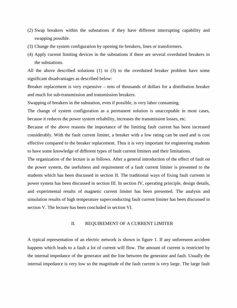
A typical representation of an electric network is shown in figure 1. If any unforeseen accident
happens which leads to a fault a lot of current will flow. The amount of current is restricted by
the internal impedance of the generator and the line between the generator and fault. Usually the
internal impedance is very low so the magnitude of the fault current is very large. The large fault
current will initiate the operation of the circuit breaker (CB) and the CB will break the circuit.
Usually the CB breaks the circuit at the zero crossing of the current wave.
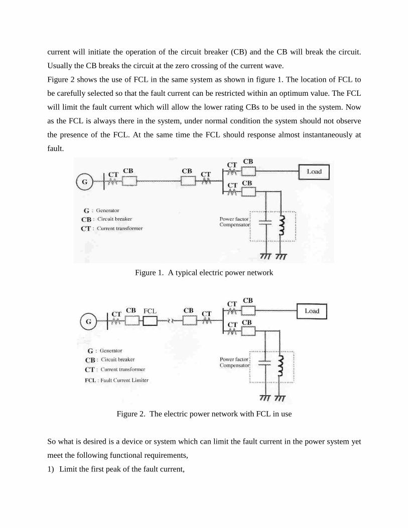
Figure 2 shows the use of FCL in the same system as shown in figure 1. The location of FCL to
be carefully selected so that the fault current can be restricted within an optimum value. The FCL
will limit the fault current which will allow the lower rating CBs to be used in the system. Now
as the FCL is always there in the system, under normal condition the system should not observe
the presence of the FCL. At the same time the FCL should response almost instantaneously at
fault.
Figure 1. A typical electric power network
Figure 2. The electric power network with FCL in use
So what is desired is a device or system which can limit the fault current in the power system yet
meet the following functional requirements,
1) Limit the first peak of the fault current,
2) Exhibits a low impedance and low energy losses in the normal state,
3) Generate no unacceptable harmonics in the normal state,
4) Eliminate sensors and control devices if their reliability compromises the overall reliability of
the system,
5) Exhibits a smooth and gradual change of impedance from the normal mode to fault mode and
vice-versa,
6) Compactness,
7) Fail-safe operation,
8) Zero reset time.
Of course it is difficult to meet all the above requirements in practice. The actual characteristics
of the FCL should be as close as possible to the ideal requirement.
III. TRADITIONAL WAYS OF FIXING FAULT CURRENT
The research and development of fault current limiter is as old as that of power systems. Earlier,
most of the researches were not focused on limiting the fault current but basically on breaking the
circuit to isolate the fault and thus prevent damage to costly equipment. Many approaches to
limiting fault currents have been proposed in the past which include the use of circuit breakers
with ultra-high fault current rating, high impedance transformers, current limiting fuses, air-core
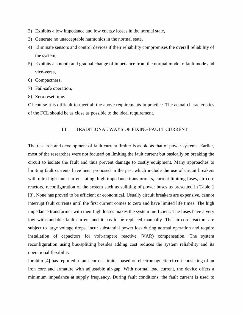
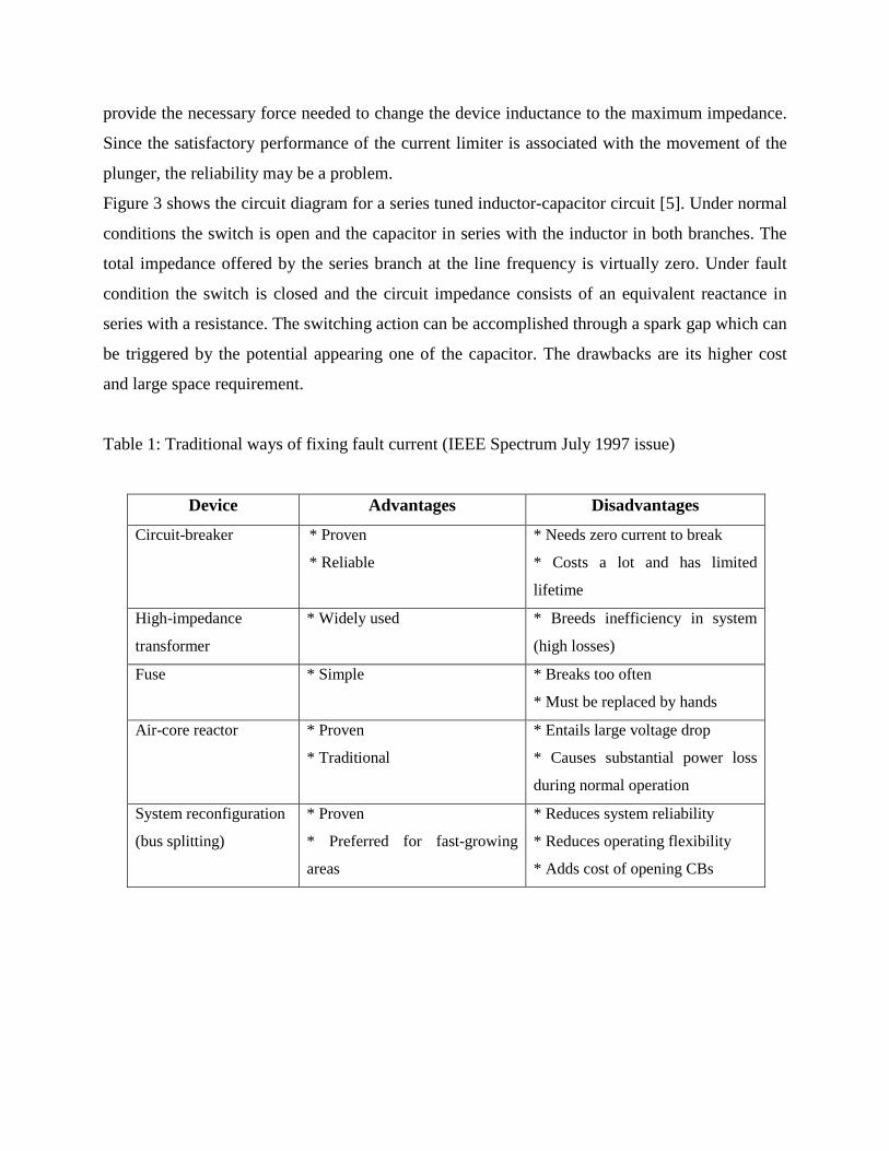
reactors, reconfiguration of the system such as splitting of power buses as presented in Table 1
[3]. None has proved to be efficient or economical. Usually circuit breakers are expensive, cannot
interrupt fault currents until the first current comes to zero and have limited life times. The high
impedance transformer with their high losses makes the system inefficient. The fuses have a very
low withstandable fault current and it has to be replaced manually. The air-core reactors are
subject to large voltage drops, incur substantial power loss during normal operation and require
installation of capacitors for volt-ampere reactive (VAR) compensation. The system
reconfiguration using bus-splitting besides adding cost reduces the system reliability and its
operational flexibility.
Ibrahim [4] has reported a fault current limiter based on electromagnetic circuit consisting of an
iron core and armature with adjustable air-gap. With normal load current, the device offers a
minimum impedance at supply frequency. During fault conditions, the fault current is used to
provide the necessary force needed to change the device inductance to the maximum impedance.
Since the satisfactory performance of the current limiter is associated with the movement of the
plunger, the reliability may be a problem.
Figure 3 shows the circuit diagram for a series tuned inductor-capacitor circuit [5]. Under normal
conditions the switch is open and the capacitor in series with the inductor in both branches. The
total impedance offered by the series branch at the line frequency is virtually zero. Under fault
condition the switch is closed and the circuit impedance consists of an equivalent reactance in
series with a resistance. The switching action can be accomplished through a spark gap which can
be triggered by the potential appearing one of the capacitor. The drawbacks are its higher cost
and large space requirement.
Table 1: Traditional ways of fixing fault current (IEEE Spectrum July 1997 issue)
Device Advantages Disadvantages
Circuit-breaker * Proven
* Reliable
* Needs zero current to break
* Costs a lot and has limited
lifetime
High-impedance
transformer
* Widely used * Breeds inefficiency in system
(high losses)
Fuse * Simple * Breaks too often
* Must be replaced by hands
Air-core reactor * Proven
* Traditional
* Entails large voltage drop
* Causes substantial power loss
during normal operation
System reconfiguration
(bus splitting)
* Proven
* Preferred for fast-growing
areas
* Reduces system reliability
* Reduces operating flexibility
* Adds cost of opening CBs
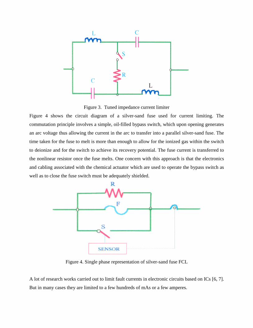
Figure 3. Tuned impedance current limiter
Figure 4 shows the circuit diagram of a silver-sand fuse used for current limiting. The
commutation principle involves a simple, oil-filled bypass switch, which upon opening generates
an arc voltage thus allowing the current in the arc to transfer into a parallel silver-sand fuse. The
time taken for the fuse to melt is more than enough to allow for the ionized gas within the switch
to deionize and for the switch to achieve its recovery potential. The fuse current is transferred to
the nonlinear resistor once the fuse melts. One concern with this approach is that the electronics
and cabling associated with the chemical actuator which are used to operate the bypass switch as
well as to close the fuse switch must be adequately shielded.
Figure 4. Single phase representation of silver-sand fuse FCL
A lot of research works carried out to limit fault currents in electronic circuits based on ICs [6, 7].
But in many cases they are limited to a few hundreds of mAs or a few amperes.
The existing fault current limiting devices/systems still fall short of addressing one or more of the
following concerns: economic, current capacity, efficiency or reliability. Therefore there is
currently a motivation to explore alternative approaches to fault current limiting.
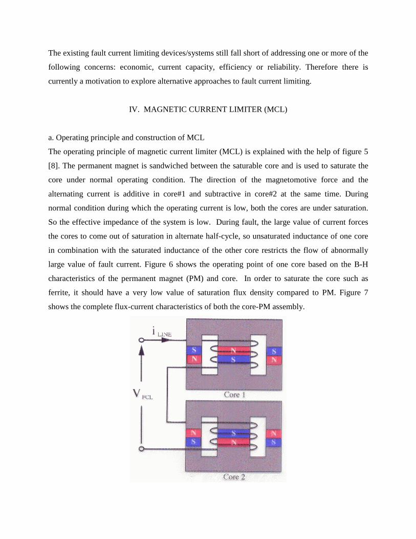
IV. MAGNETIC CURRENT LIMITER (MCL)
a. Operating principle and construction of MCL
The operating principle of magnetic current limiter (MCL) is explained with the help of figure 5
[8]. The permanent magnet is sandwiched between the saturable core and is used to saturate the
core under normal operating condition. The direction of the magnetomotive force and the
alternating current is additive in core#1 and subtractive in core#2 at the same time. During
normal condition during which the operating current is low, both the cores are under saturation.
So the effective impedance of the system is low. During fault, the large value of current forces
the cores to come out of saturation in alternate half-cycle, so unsaturated inductance of one core
in combination with the saturated inductance of the other core restricts the flow of abnormally
large value of fault current. Figure 6 shows the operating point of one core based on the B-H
characteristics of the permanent magnet (PM) and core. In order to saturate the core such as
ferrite, it should have a very low value of saturation flux density compared to PM. Figure 7
shows the complete flux-current characteristics of both the core-PM assembly.
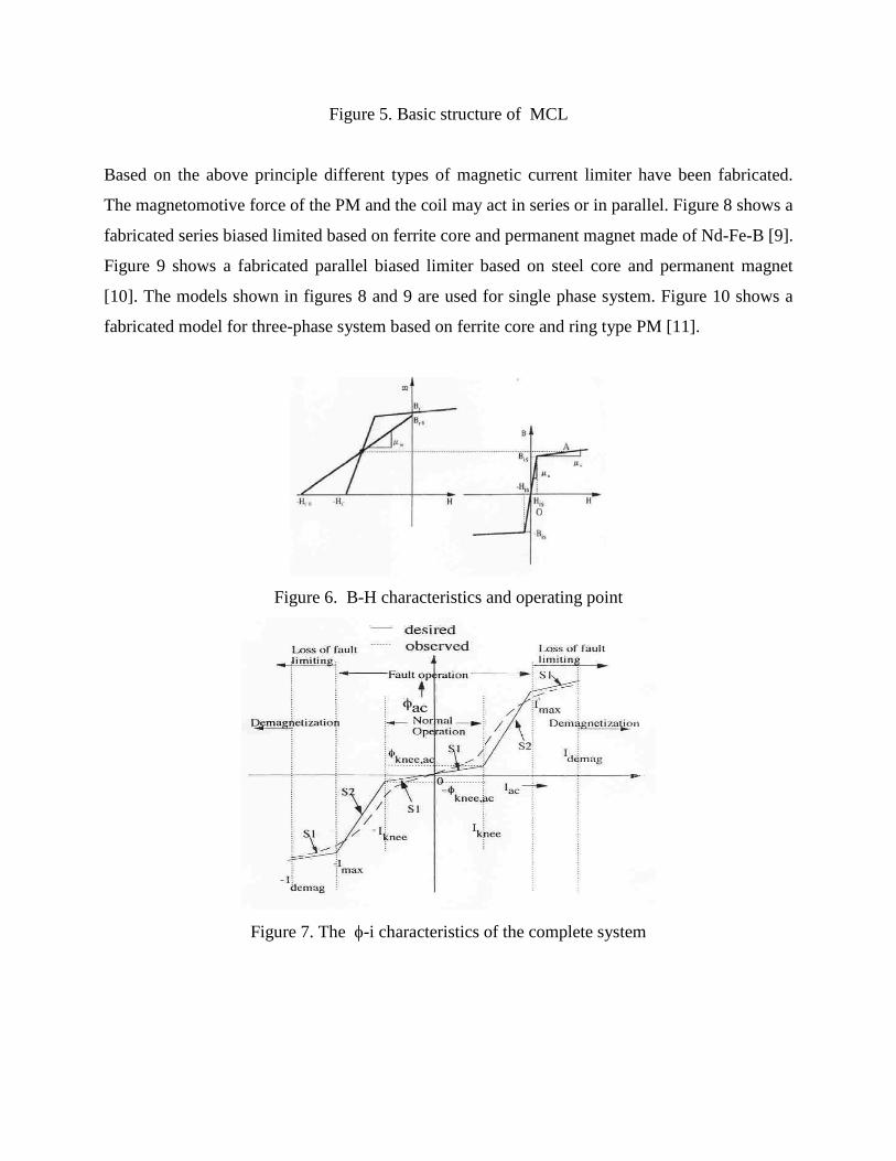
Figure 5. Basic structure of MCL
Based on the above principle different types of magnetic current limiter have been fabricated.
The magnetomotive force of the PM and the coil may act in series or in parallel. Figure 8 shows a
fabricated series biased limited based on ferrite core and permanent magnet made of Nd-Fe-B [9].
Figure 9 shows a fabricated parallel biased limiter based on steel core and permanent magnet
[10]. The models shown in figures 8 and 9 are used for single phase system. Figure 10 shows a
fabricated model for three-phase system based on ferrite core and ring type PM [11].
Figure 6. B-H characteristics and operating point
Figure 7. The φ-i characteristics of the complete system
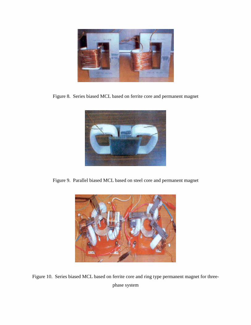
Figure 8. Series biased MCL based on ferrite core and permanent magnet
Figure 9. Parallel biased MCL based on steel core and permanent magnet
Figure 10. Series biased MCL based on ferrite core and ring type permanent magnet for three-
phase system

b. Design Criterion and Application Areas Of MCL
The basic design criterion of magnetic curent limiter is explained in this section. During the fault
condition to avoid the PM to be in the loss of current limting and demagntization zone as shown
in figure 7, the following condition is to be satisfied.
maxc mH l NI≥ (1)
where Hc is the coercive force of the PM and lm is the length of the PM. Imax is the maximum
current allowed during the fault condition. Hc is dictated by the PM itself, so PM with higher
value of coercive force is to be selected. The minimum value of N, i.e. the turn of the coil may be
1. So the maximum value of current i.e. system level is dependent on the length of the magnet.
Under normal condition the voltage drop across the MCL is to be very low and is given by
2(2 ) 4NOR s s sV X I fL I fL I= = π = π (2)
The voltage across the MCL during fault condition to be very large and is given by
2 ( )FAULT u s uV X I f L L I= = π + (3)
where Ls and Lu are the saturated and unsaturated inductance respectively and are given by 2
sm s
NLR R
=+
and 2
um u
NLR R
=+
(4a, b)
where Rm, Rs and Ru are the reluctance of PM, saturated reluctance of the core and unsaturated
reluctance of the core respectively and are given by
mm
m
lRS
=µ
, cores
s
lRS
=µ
and coreu
u
lRS
=µ
(5a, b, c)
where S is the common area of the core or PM, µm, µs and µu are permeabilities of PM, saturated
core and unsaturated core respectively.
Under fault condition the full voltage appears across the MCL.
So we can write Vsupply = XuIFAULT (6)
So the ratio of the normal voltage drop across MCL to the supply voltage is given by
sup
21 1 2 1
1NOR s NOR s s
uply u FAULT u s us
V X I X LLV X I k X k L L k
L
= = = =+ +
(7) ; k is the ratio of IFAULT to INOR.
From (4a, b) and (5a, b, c) we can write
1u m core
s s m
L lL l
µ= +
µ (8); the reluctance Ru is neglected with respect to Rm.
For NdFeB PM, the permeability 01.8mµ ≈ µ and assuming lcore/lm = 100, we get
1801u
s rs
LL
= +µ
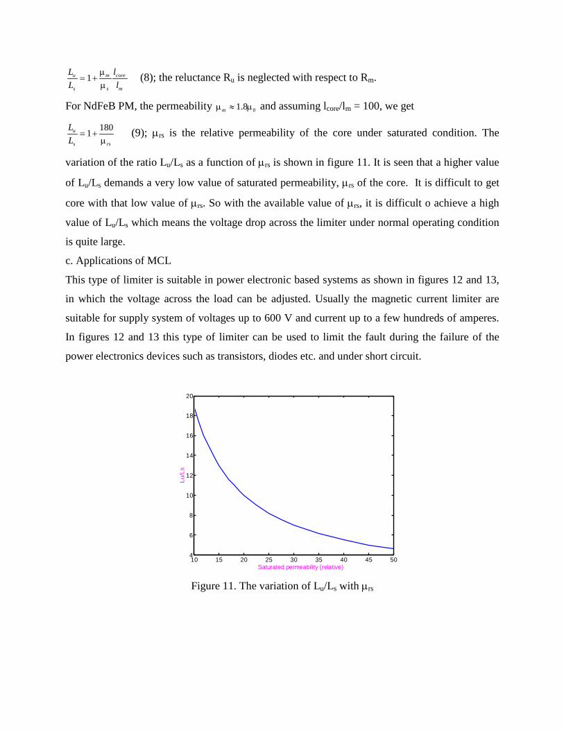
(9); µrs is the relative permeability of the core under saturated condition. The
variation of the ratio Lu/Ls as a function of µrs is shown in figure 11. It is seen that a higher value
of Lu/Ls demands a very low value of saturated permeability, µrs of the core. It is difficult to get
core with that low value of µrs. So with the available value of µrs, it is difficult o achieve a high
value of Lu/Ls which means the voltage drop across the limiter under normal operating condition
is quite large.
c. Applications of MCL
This type of limiter is suitable in power electronic based systems as shown in figures 12 and 13,
in which the voltage across the load can be adjusted. Usually the magnetic current limiter are
suitable for supply system of voltages up to 600 V and current up to a few hundreds of amperes.
In figures 12 and 13 this type of limiter can be used to limit the fault during the failure of the
power electronics devices such as transistors, diodes etc. and under short circuit.
Figure 11. The variation of Lu/Ls with µrs
10 15 20 25 30 35 40 45 504
6
8
10
12
14
16
18
20
Saturated permeability (relative)
Lu/L
s
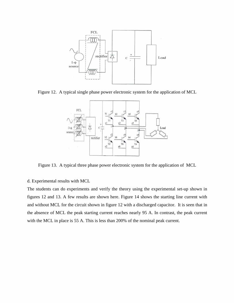
Figure 12. A typical single phase power electronic system for the application of MCL
Figure 13. A typical three phase power electronic system for the application of MCL
d. Experimental results with MCL
The students can do experiments and verify the theory using the experimental set-up shown in
figures 12 and 13. A few results are shown here. Figure 14 shows the starting line current with
and without MCL for the circuit shown in figure 12 with a discharged capacitor. It is seen that in
the absence of MCL the peak starting current reaches nearly 95 A. In contrast, the peak current
with the MCL in place is 55 A. This is less than 200% of the nominal peak current.
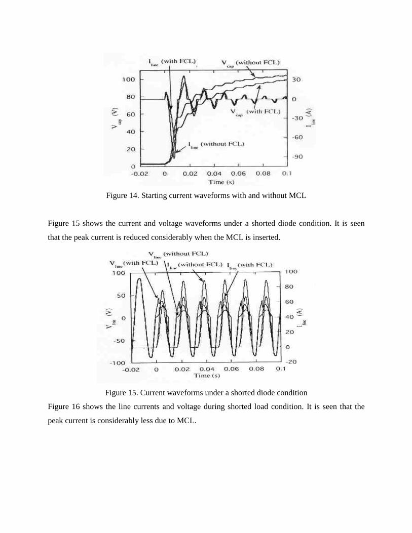
Figure 14. Starting current waveforms with and without MCL
Figure 15 shows the current and voltage waveforms under a shorted diode condition. It is seen
that the peak current is reduced considerably when the MCL is inserted.
Figure 15. Current waveforms under a shorted diode condition
Figure 16 shows the line currents and voltage during shorted load condition. It is seen that the
peak current is considerably less due to MCL.
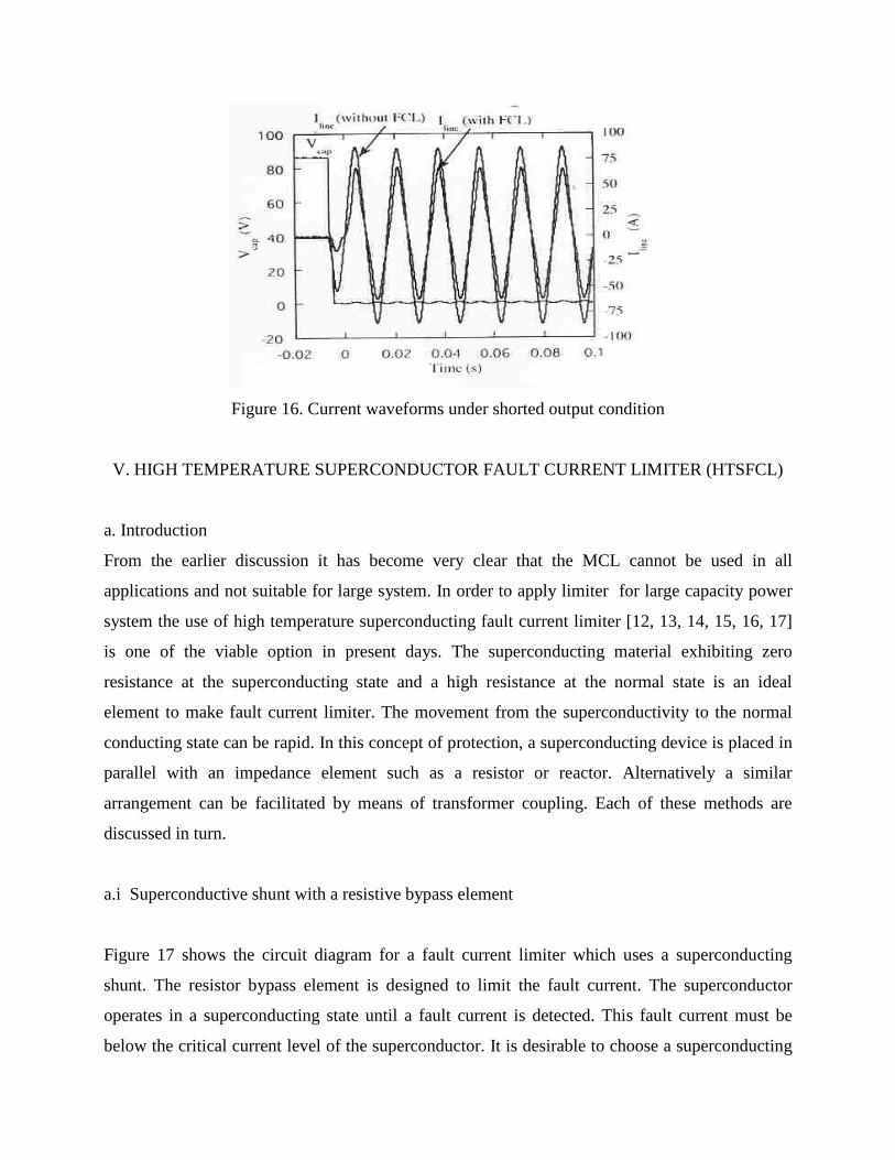
Figure 16. Current waveforms under shorted output condition
V. HIGH TEMPERATURE SUPERCONDUCTOR FAULT CURRENT LIMITER (HTSFCL)
a. Introduction
From the earlier discussion it has become very clear that the MCL cannot be used in all
applications and not suitable for large system. In order to apply limiter for large capacity power
system the use of high temperature superconducting fault current limiter [12, 13, 14, 15, 16, 17]
is one of the viable option in present days. The superconducting material exhibiting zero
resistance at the superconducting state and a high resistance at the normal state is an ideal
element to make fault current limiter. The movement from the superconductivity to the normal
conducting state can be rapid. In this concept of protection, a superconducting device is placed in
parallel with an impedance element such as a resistor or reactor. Alternatively a similar
arrangement can be facilitated by means of transformer coupling. Each of these methods are
discussed in turn.
a.i Superconductive shunt with a resistive bypass element
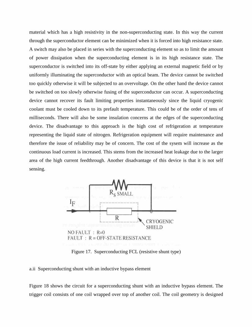
Figure 17 shows the circuit diagram for a fault current limiter which uses a superconducting
shunt. The resistor bypass element is designed to limit the fault current. The superconductor
operates in a superconducting state until a fault current is detected. This fault current must be
below the critical current level of the superconductor. It is desirable to choose a superconducting
material which has a high resistivity in the non-superconducting state. In this way the current
through the superconductor element can be minimized when it is forced into high resistance state.
A switch may also be placed in series with the superconducting element so as to limit the amount
of power dissipation when the superconducting element is in its high resistance state. The
superconductor is switched into its off-state by either applying an external magnetic field or by
uniformly illuminating the superconductor with an optical beam. The device cannot be switched
too quickly otherwise it will be subjected to an overvoltage. On the other hand the device cannot
be switched on too slowly otherwise fusing of the superconductor can occur. A superconducting
device cannot recover its fault limiting properties instantaneously since the liquid cryogenic
coolant must be cooled down to its prefault temperature. This could be of the order of tens of
milliseconds. There will also be some insulation concerns at the edges of the superconducting
device. The disadvantage to this approach is the high cost of refrigeration at temperature
representing the liquid state of nitrogen. Refrigeration equipment will require maintenance and
therefore the issue of reliability may be of concern. The cost of the sysem will increase as the
continuous load current is increased. This stems from the increased heat leakage due to the larger
area of the high current feedthrough. Another disadvantage of this device is that it is not self
sensing.
Figure 17. Superconducting FCL (resistive shunt type)
a.ii Superconducting shunt with an inductive bypass element
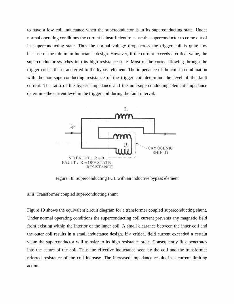
Figure 18 shows the circuit for a superconducting shunt with an inductive bypass element. The
trigger coil consists of one coil wrapped over top of another coil. The coil geometry is designed
to have a low coil inductance when the superconductor is in its superconducting state. Under
normal operating conditions the current is insufficient to cause the superconductor to come out of
its superconducting state. Thus the normal voltage drop across the trigger coil is quite low
because of the minimum inductance design. However, if the current exceeds a critical value, the
superconductor switches into its high resistance state. Most of the current flowing through the
trigger coil is then transferred to the bypass element. The impedance of the coil in combination
with the non-superconducting resistance of the trigger coil determine the level of the fault
current. The ratio of the bypass impedance and the non-superconducting element impedance
determine the current level in the trigger coil during the fault interval.
Figure 18. Superconducting FCL with an inductive bypass element
a.iii Transformer coupled superconducting shunt
Figure 19 shows the equivalent circuit diagram for a transformer coupled superconducting shunt.
Under normal operating conditions the superconducting coil current prevents any magnetic field
from existing within the interior of the inner coil. A small clearance between the inner coil and
the outer coil results in a small inductance design. If a critical field current exceeded a certain
value the superconductor will transfer to its high resistance state. Consequently flux penetrates
into the centre of the coil. Thus the effective inductance seen by the coil and the transformer
referred resistance of the coil increase. The increased impedance results in a current limiting
action.
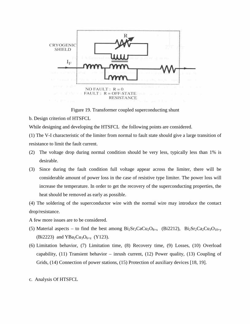
Figure 19. Transformer coupled superconducting shunt
b. Design criterion of HTSFCL
While designing and developing the HTSFCL the following points are considered.
(1) The V-I characteristic of the limiter from normal to fault state should give a large transition of
resistance to limit the fault current.
(2) The voltage drop during normal condition should be very less, typically less than 1% is
desirable.
(3) Since during the fault condition full voltage appear across the limiter, there will be
considerable amount of power loss in the case of resistive type limiter. The power loss will
increase the temperature. In order to get the recovery of the superconducting properties, the
heat should be removed as early as possible.
(4) The soldering of the superconductor wire with the normal wire may introduce the contact
drop/resistance.
A few more issues are to be considered.
(5) Material aspects – to find the best among Bi2Sr2CaCu2O8+x (Bi2212), Bi2Sr2Ca2Cu3O10+y
(Bi2223) and YBa2Cu3O6+z (Y123).
(6) Limitation behavior, (7) Limitation time, (8) Recovery time, (9) Losses, (10) Overload
capability, (11) Transient behavior – inrush current, (12) Power quality, (13) Coupling of
Grids, (14) Connection of power stations, (15) Protection of auxiliary devices [18, 19].
c. Analysis Of HTSFCL
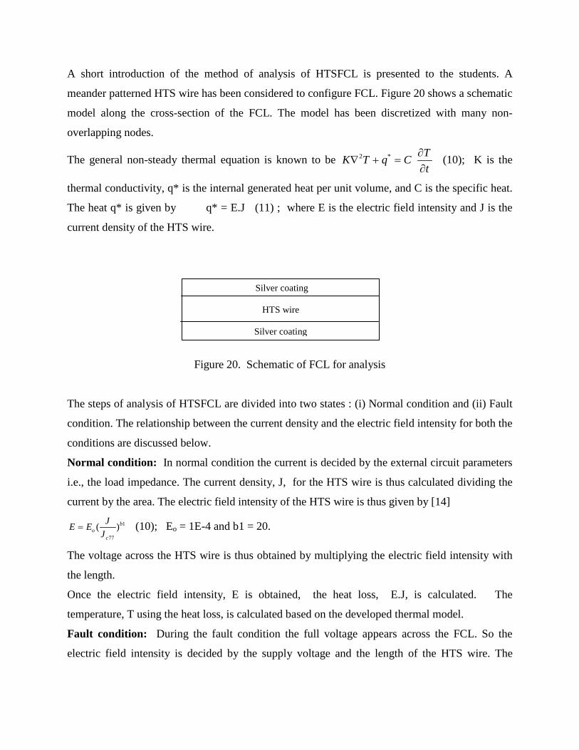
A short introduction of the method of analysis of HTSFCL is presented to the students. A
meander patterned HTS wire has been considered to configure FCL. Figure 20 shows a schematic
model along the cross-section of the FCL. The model has been discretized with many non-
overlapping nodes.
The general non-steady thermal equation is known to be 2 * TK T q Ct
∂∇ + =
∂ (10); K is the
thermal conductivity, q* is the internal generated heat per unit volume, and C is the specific heat.
The heat q* is given by q* = E.J (11) ; where E is the electric field intensity and J is the
current density of the HTS wire.
Figure 20. Schematic of FCL for analysis
The steps of analysis of HTSFCL are divided into two states : (i) Normal condition and (ii) Fault
condition. The relationship between the current density and the electric field intensity for both the
conditions are discussed below.
Normal condition: In normal condition the current is decided by the external circuit parameters
i.e., the load impedance. The current density, J, for the HTS wire is thus calculated dividing the
current by the area. The electric field intensity of the HTS wire is thus given by [14]
1
77
( )bo
c
JE EJ
= (10); Eo = 1E-4 and b1 = 20.
The voltage across the HTS wire is thus obtained by multiplying the electric field intensity with
the length.
Once the electric field intensity, E is obtained, the heat loss, E.J, is calculated. The
temperature, T using the heat loss, is calculated based on the developed thermal model.
Fault condition: During the fault condition the full voltage appears across the FCL. So the
electric field intensity is decided by the supply voltage and the length of the HTS wire. The
Silver coating
HTS wire
Silver coating
current density of the HTS wire is a function of the operating temperature and the electric field
intensity.
The temperature dependence of the critical current density is expressed as [14]
( )(1 )
( 0)xc
c c
J T TJ T T
= −=
(12)
Tc and x for different HTS materials are given by
Ag/Bi-2223: Tc = 105-110 K x = 1.4
Ag/Bi-2212: Tc = 85-92 K x = 1.8
Y-123: Tc = 88 K x = 1.2
Based on the operation at 77 K with liquid nitrogen the current density during fault condition is
given by 1
177 ( ) ( )
77xc b
cc o
T T EJ JT E
−=
− (13)
The current density of each node is thus calculated and the current of each section is obtained
multiplying the corresponding area associated with each node. The total current is calculated by
taking the sum of all the current along the cross-section of the HTS wire.
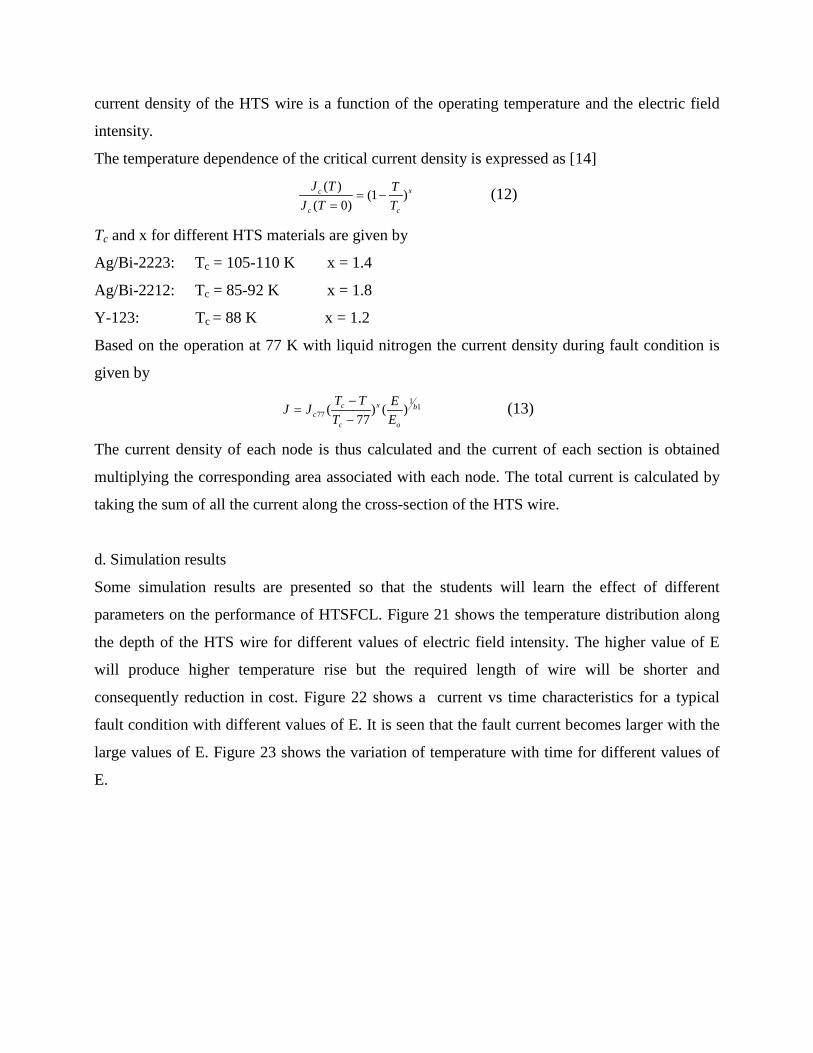
d. Simulation results
Some simulation results are presented so that the students will learn the effect of different
parameters on the performance of HTSFCL. Figure 21 shows the temperature distribution along
the depth of the HTS wire for different values of electric field intensity. The higher value of E
will produce higher temperature rise but the required length of wire will be shorter and
consequently reduction in cost. Figure 22 shows a current vs time characteristics for a typical
fault condition with different values of E. It is seen that the fault current becomes larger with the
large values of E. Figure 23 shows the variation of temperature with time for different values of
E.
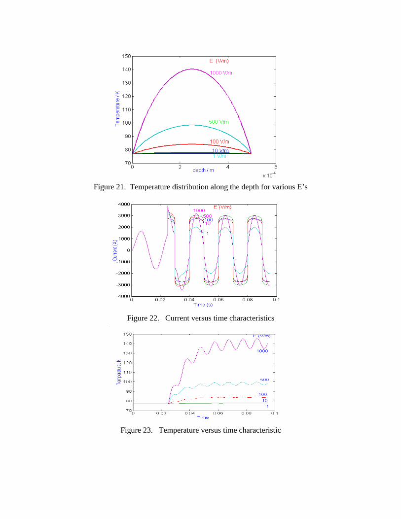
Figure 21. Temperature distribution along the depth for various E’s
Figure 22. Current versus time characteristics
Figure 23. Temperature versus time characteristic
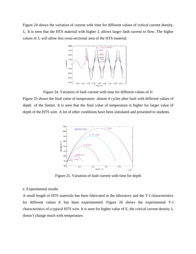
Figure 24 shows the variation of current with time for different values of critical current density,
Jc. It is seen that the HTS material with higher Jc allows larger fault current to flow. The higher
values of Jc will allow less cross-sectional area of the HTS material.
Figure 24. Variation of fault current with time for different values of Jc
Figure 25 shows the final value of temperature almost 4 cycles after fault with different values of
depth of the limiter. It is seen that the final value of temperature is higher for larger value of
depth of the HTS wire. A lot of other conditions have been simulated and presented to students.
Figure 25. Variation of fault current with time for depth
e. Experimental results
A small length of HTS materials has been fabricated in the laboratory and the T-J characteristics
for different values E has been experimented. Figure 26 shows the experimental T-J
characteristics of a typical HTS wire. It is seen for higher value of E, the critical current density Jc
doesn’t change much with temperature.
Figure 26. Experimental T-J characteristics of HTS wire
VI. CONCLUSIONS
This paper is a one-hour lecture on the topic of fault current limiter presented to engineering
students. The lecture has started with the causes and effects of fault on power systems. The
traditional ways of fixing fault current have been described. The detailed analysis of two types of
fault current limiters: based on magnetic materials and high temperature superconductor materials
have been presented. With some modification (elimination of mathematical part) the lecture can
be presented to general public.
REFERENCES
[1] S.N.Talukdar, J. Apt, M.Ilic, L.B.Lave and M.G.Morgan, “Cascading Failures: Survival versus Prevention”, The Electricity Journal, Elsevier Inc., November 2003, pp. 25-31. [2] D. White, A. Roschelle, P.Peterson, D.Schlicel, B.Biewald and W.Steinhurst, “The 2003
Blackout: Solutions that won’t Cost a Fortune”, The Electricity Journal, Elsevier Inc., November
2003, pp. 43-53.
[3] E. Leung, “Surge Protection for Power Grids”, IEEE Spectrum, July 1997, pp. 26-30.
[4] E. S. Ibrahim, “Electromagnetic Fault Current Limiter”, Electric Power System Research,
Vol. 42, 1997, pp. 189-194.
J(E,T) Jc=250A/cm2, ρ.Jc=500V/m
1.0E+03
1.0E+04
1.0E+05
1.0E+06
1.0E+07
75 100 125
T (K)
J (A/m
2)
1 V/m3 V/m10 V/m30 V/m100 V/m1000 V/m
[5] V.H.Tahiliani and J.W.Porter, “Fault Current Limiters – An Overview of EPRI Research”,
IEEE Transactions on Power Apparatus and Systems, Vol. PAS-99, no. 5, 1980, pp. 1964-1969.
[6] “Simple Current Limiter for DC 2770- Based Charger”, Maxim Application Note 2044,
Dallas Semiconductor (ww.maxim-ic.com/an2044), 2003.
[7] “Flexible Hot-Swap Current Limiter Allows Thermal Protection”, Maxim Application Note
390, Dallas Semiconductor (ww.maxim-ic.com/an390), 2001.
[8] S.C.Mukhopadhyay, “Synthesis and Implementation of Magnetic Current Limiter”, Doctor of
Engineering thesis, Faculty of Engineering, Kanazawa University, Japan, March 2000.
[9] S.C.Mukhopadhyay, M.Iwahara, S.Yamada and F.P.Dawson, " Analysis, design and
experimental results for a passive current limiting device", IEE proceeding on Electric Power
Applications, vol. 146, no. 3, pp. 309-316, May 1999.
[10] M.Iwahara, S.C.Mukhopadhyay, S.Yamada and F.P.Dawson, "Development of passive
fault current limiter in parallel biasing mode", IEEE transc. on Magnetics, Vol. 35, No. 5, pp
3523-3525, September 1999.
[11] S.C.Mukhopadhyay, F.P.Dawson, M.Iwahara and S.Yamada, “A novel compact magnetic
current limiter for three phase applications”, IEEE transc. on Magnetics, Vol. 36, No. 5, pp.
3568-3570, September 2000.
[12] P. Malkin and D. Klaus, “Cap That Current”, IEE Review, March 2001, pp. 41-45.
[13] W.Paul, et.al., “Test of 1.2 MVA high-Tc superconducting fault current limiter”, Proc. On
Superconducting Sci. Technol., IOP Publishing Ltd., 10 (1997), 914-918.
[14] G.E.Marsh and A.M.Wolsky, “AC losses in high-temperature superconductors and the
importance of these losses to the future use of HTS in the power sector”, Report submitted to
International Energy Agency, USA, May 2000.
[15] M. Steurer, H. Brechna and K. Frohlich, “A Nitrogen Gas Cooled, Hybrid High
Temperature Superconducting Fault Current Limiter”, IEEE Transactions on Applied
Superconductivity, vol. 10, No. 1, 2000, pp. 840-844.
[16] T. Ohnishi, N. Aizawa, A.Yamagata, A. Nii and M.Shibuya, “Stability of a Shorted Nb3n
Coil Cooled by a Refrigeration for a Magnetic Shield Type Fault Current Limiter”, IEEE
Transactions on Applied Superconductivity, vol. 10, No. 1, 2000, pp. 845-848.
[17] V. Keilin, I. Kovalev, S.Kruglov, V.Stepanov, I.Shugaev and V.Shcherbakov, “Model of
HTS Three-Phase Saturated Core Fault Current Limiter”, IEEE Transactions on Applied
Superconductivity, vol. 10, No. 1, 2000, pp. 836-839.
[18] S.C.Mukhopadhyay, C.Goonaratne, M.Staines, I.Vajda, M.Iwahara and S.Yamada,
“Feasibility study of developing high temperature superconducting fault current limiter: A New
Zealand perspective”, Proc. ISEM 2003, pp. 100-101, France, May 12-14, 2003.
[19] S.C.Mukhopadhyay, C. Gooneratne and M. Staines, “Transition of magnetic current limiter
to superconducting fault current limiter”, Proceeding of AUPEC conference, paper no. 3, Sep.
28- Oct. 1, 2003, Christchurch, New Zealand.