Embed Size (px)
Citation preview
P.O. Box 270460Fort Collins, Colorado 80527
(970) 223-5556, FAX (970) 223-5578
Ayres Project No. 34-0705.00A-JK7-TX.DOC
August 1999
A-JACKS CONCRETE ARMOR UNITSChannel Lining and Pier Scour
Design Manual
Prepared for
Armortec, Inc.
Bowling Green, Kentucky
Ayres Associatesi
TABLE OF CONTENTS
1. Introduction ................................................................................................................ 1.1
1.1 General................................................................................................................... 1.11.2 Background ............................................................................................................ 1.21.3 Organization of this Manual .................................................................................... 1.21.4 Disclaimer ............................................................................................................... 1.3
2. Channel Bed and Bank Protection.............................................................................. 2.1
2.1 Fundamentals of Open Channel Flow..................................................................... 2.1
2.1.1 Basic Concepts................................................................................................ 2.12.1.2 Hydraulics of Steady Flow................................................................................ 2.22.1.3 Surface Roughness ......................................................................................... 2.42.1.4 Stable Channel Design Concepts .................................................................... 2.52.1.5 Hydraulic Forces.............................................................................................. 2.62.1.6 Hydraulic Stability of A-JACKS Concrete Armor Units ..................................... 2.82.1.7 Definition of Failure.......................................................................................... 2.82.1.8 Hydraulic Stability - The Discrete Particle Method.......................................... 2.122.1.9 Selection of Factor of Safety for Channel Revetments................................... 2.12
2.2 A-JACKS Hydraulic Performance Characteristics ................................................. 2.12
2.2.1 General.......................................................................................................... 2.122.2.2 Froude-Law Scaling ....................................................................................... 2.132.2.3 Hydraulic Resistance: Manning's n .............................................................. 2.132.2.4 Critical Shear Stress ...................................................................................... 2.14
2.3 A-JACKS Design Procedure for Bed and Bank Protection.................................... 2.18
2.3.1 General.......................................................................................................... 2.182.3.2 Use of Design Charts and the Factor of Safety Method ................................. 2.182.3.3 Bedding Considerations................................................................................. 2.26
2.4 A-JACKS Installation Guidelines ........................................................................... 2.28
2.4.1 Subgrade Preparation.................................................................................... 2.282.4.2 Placement of Geotextile................................................................................. 2.292.4.3 Placement of the A-JACKS System ............................................................... 2.292.4.4 Finishing ........................................................................................................ 2.292.4.5 Inspection ...................................................................................................... 2.29
3. Pier Scour Applications .............................................................................................. 3.1
3.1 Mechanics of Pier Scour ......................................................................................... 3.13.2 Stability Paradigms ................................................................................................. 3.33.3 Layout and Installation ............................................................................................ 3.9
Ayres Associatesii
TABLE OF CONTENTS (continued)
3.3.1 Geometry......................................................................................................... 3.93.3.2 A-JACKS Placement........................................................................................ 3.93.3.3 Bedding Considerations................................................................................... 3.9
4. Product Information .................................................................................................... 4.1
5. References and Appendices....................................................................................... 5.1
LIST OF FIGURES
Figure 1.1. A-JACKS used for bank toe stabilization. ..................................................... 1.1
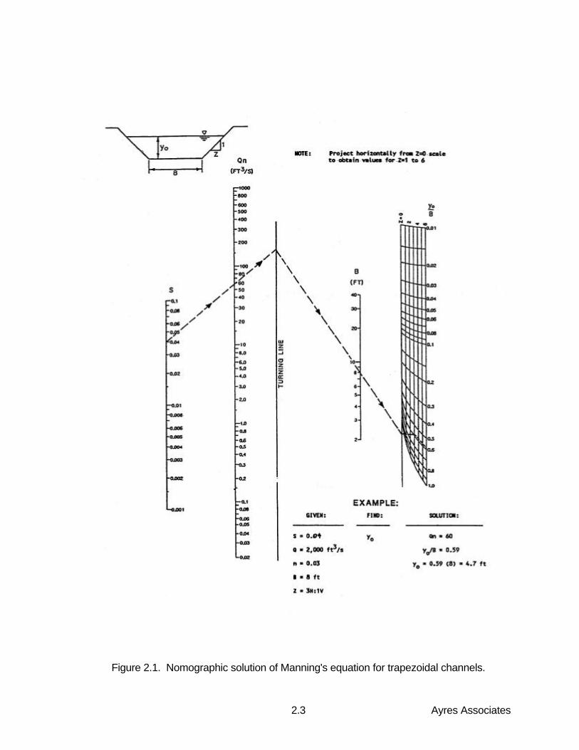
Figure 2.1. Nomographic solution of Manning's equation for trapezoidal channels......... 2.3
Figure 2.2a. Shear stress distribution on the boundary of a trapezoidal channel in a straight reach......................................................................................... 2.7
Figure 2.2b. Shear stress concentration areas in channel bend ....................................... 2.7
Figure 2.3. Kb factor for computing shear stresses at channel bends. ............................ 2.9
Figure 2.4. A-JACKS force diagram showing rotational moments. ............................... 2.10
Figure 2.5. Protection length Lp downstream of channel bends. ................................... 2.11
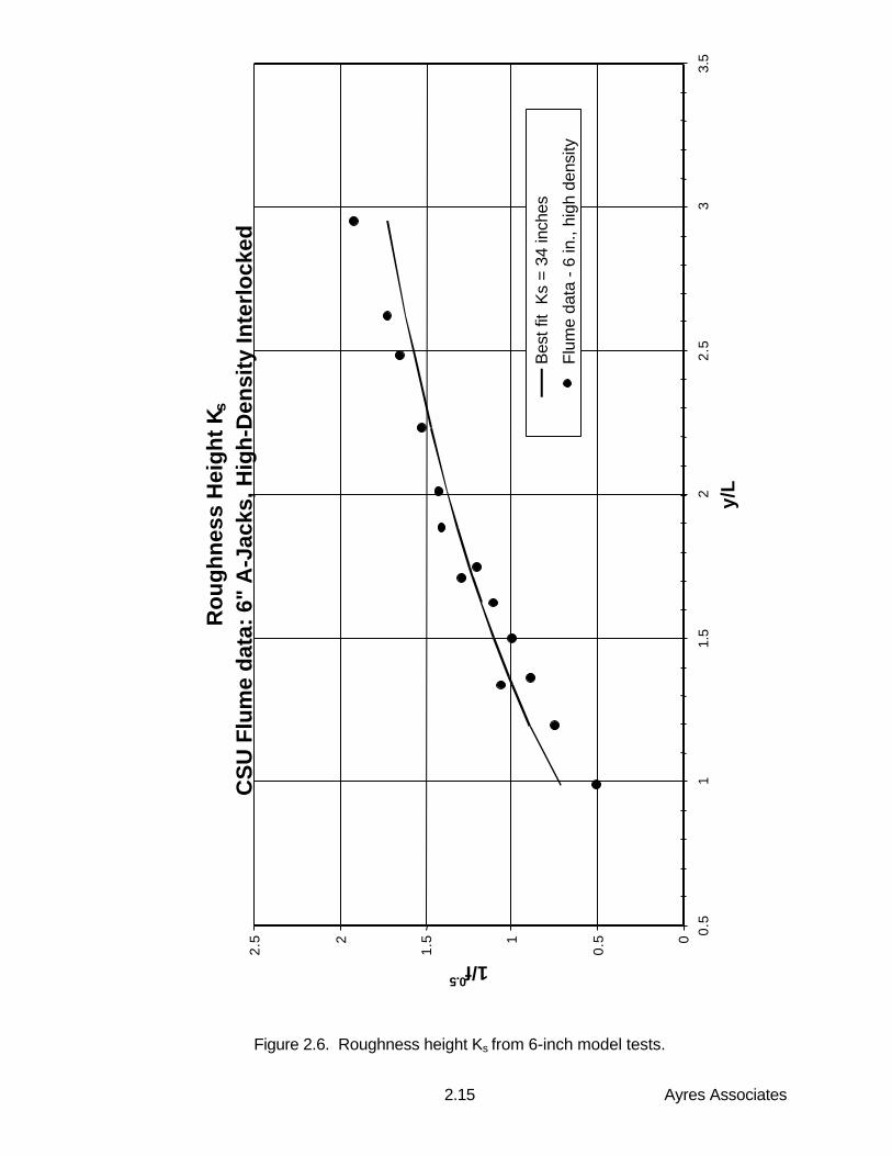
Figure 2.6. Roughness height Ks from 6-inch model tests. ........................................... 2.15
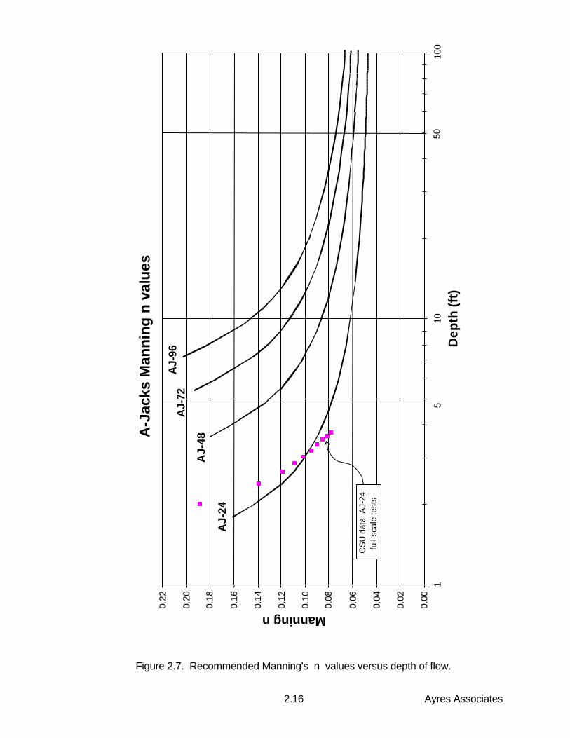
Figure 2.7. Recommended Manning's n values versus depth of flow. ........................ 2.16
Figure 2.8. Hydraulic data from 6-inch model test (CSU Run No. 6)............................. 2.17
Figure 2.9. Recommended limiting values of shear stress versus bed slope. ............... 2.19
Figure 2.10. Recommended limiting values of velocity versus bed slope........................ 2.20
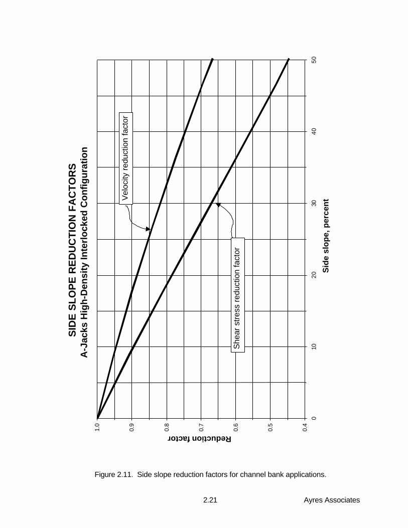
Figure 2.11. Side slope reduction factors for channel bank applications......................... 2.21
Figure 2.12. Configuration of A-JACKS for proper fit. ..................................................... 2.30
Figure 2.13. Bank installation. ........................................................................................ 2.31
Figure 2.14. Bed and Bank installation. .......................................................................... 2.32
Ayres Associatesiii
LIST OF FIGURES (continued)
Figure 3.1. Schematic representation of scour at a Cylindrical Pier ................................ 3.1
Figure 3.2. Schematic representation of the area of the Horseshoe Vortex.................... 3.2
Figure 3.3. Schematic of Scour Hole Topwidth (Richardson and Davis 1995). ............... 3.3
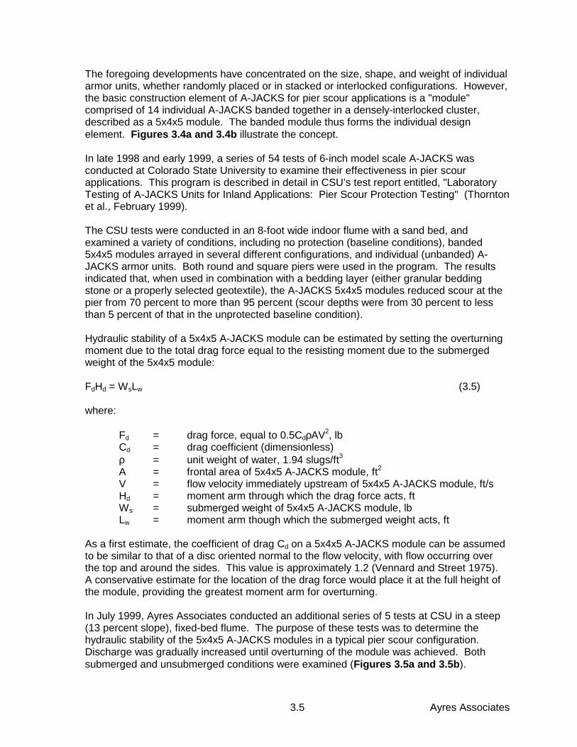
Figure 3.4a. A-JACKS 5x4x5 modules in a typical pier scour installation.......................... 3.6
Figure 3.4b. Frontal view showing 5x4x5 A-JACKS modules............................................ 3.6
Figure 3.5a. Stability test of 5x4x5 A-JACKS modules, unsubmerged conditions............. 3.7
Figure 3.5b. Stability test of 5x4x5 A-JACKS modules, submerged conditions................. 3.6
Figure 3.6. Placement of 5x4x5 A-JACKS modules for pier scour protection. .............. 3.10
Figure 3.7a. Bedding detail showing two layers of granular bedding stone above native streambed material................................................................ 3.12
Figure 3.7b. Bedding detail showing ballast stone on top of geotextile ........................... 3.12
LIST OF TABLES
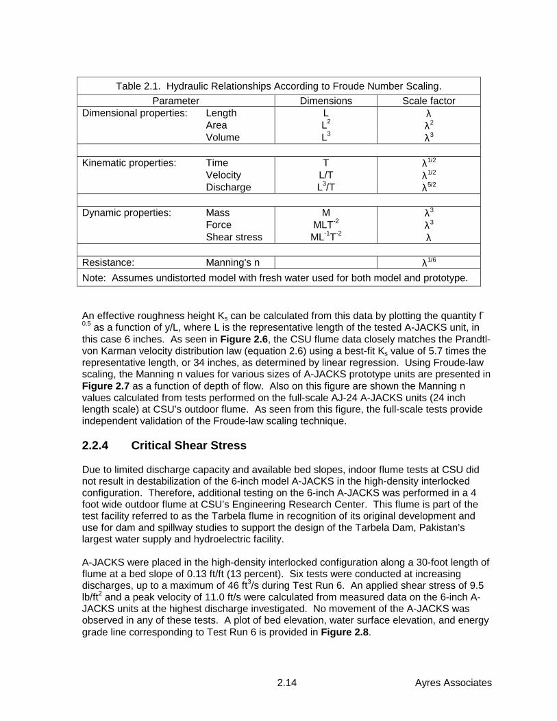
Table 2.1. Hydraulic Relationships According to Froude Number Scaling. ..................... 2.14
Table 2.2. Scaled Values of Shear Stress and Velocity for A-JACKS Systems at 13...... 2.18
Table 2.3. Recommended Geotextile Strength Requirements. ....................................... 2.27
Table 3.1. Results of 6-Inch 5x4x5 Module A-JACKS Hydraulic Stability Tests. ............... 3.8
Table 3.2. Hydraulic Stability of Prototype Size 5x4x5 A-JACKS Modules........................ 3.8
Table 3.3. Recommended Properties of Uppermost Layer of bedding stone for use with A-JACKS armor units ................................................................. 3.11
Ayres Associates1.1
1. INTRODUCTION
1.1 General
This manual provides technical information and guidelines for the hydraulic design of stableopen-channel conveyanceways and pier scour countermeasures using A-JACKS concretearmor units. The interlocking A-JACKS system is assembled into a continuous yet flexiblematrix that provides protection against high-velocity flow. The matrix of A-JACKS units hasa high void ratio and can be backfilled with topsoil and vegetated to increase the stability ofthe system. The system provides a nonerodible boundary between the channel subgradeand the potentially damaging flow of water.
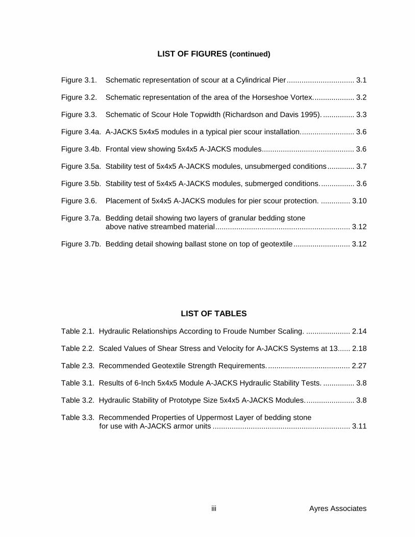
The A-JACKS system may be used for bank toe stabilization in combination with "softer"techniques to secure the upper bank. A-JACKS can also be used as an armoringcountermeasure to minimize the amount of local pier scour at bridges. The ability of the A-JACKS system to dissipate energy and resist the erosive forces of flowing water allows thesystem to protect channel boundaries from scour and erosion.
Figure 1.1. A-JACKS used for bank toe stabilization.
The A-JACKS system is presented as an alternative to dumped rock riprap, grouted rock,gabions, and other heavy duty channel and pier scour protection systems. In somegeographic locations the size, quality and gradation of rock required for a particularapplication may be difficult to obtain. The cost of transporting rock over large distances canbe quite expensive. Rock of poor quality can potentially break into smaller pieces andbecome mobilized by the flow, and therefore not provide the required protection. Riprapperformance is also dependent on an appropriate gradation of material. The ability tomanufacture the A-JACKS system at a consistent size and quality (durability) allows it tomaintain a positive interlock and function reliably at the required level of performance.
Ayres Associates1.2
The design relations presented in this manual are developed from physical principles ofopen channel flow supported by extensive laboratory testing. They represent semi-empirical, dominant-process models that are internally consistent and well suited as designtools. Because the relations represent a simplification of a complex process, the underlyingassumptions of the methods, areas of applicability, and limits of the techniques are alsodescribed.
1.2 Background
Manufactured concrete armor units have been used in coastal applications since the 1800s.They have been utilized successfully as breakwaters, groins, seawalls and other coastalrevetments. Armor units are preferred over riprap in certain ocean environments where theavailability of large rock that is suitable to resist the impact forces of waves is limited. Incases were the cost of large rock is excessive, manufactured concrete armor units havebeen a preferred alternative. The advantages of armor units are that they are available inlarge sizes, the interlocking characteristics provide a high level of stability, and they can beproduced at a consistent level of quality.
The use and consideration of armor units for erosion protection in the river environment hasgrown in the last century. The U.S. Army Corps of Engineers has employed concrete armorunits for channel protection on the Mississippi River. Japanese engineers have used armorunits to protect bridge piers at highway and railway crossings. Several laboratories havetested concrete armor units for use in open channel conveyance systems. The U.S. ArmyCorps of Engineers’ Waterways Experiment Station, Turner Fairbanks Laboratory of theFederal Highway Administration, Colorado State University’s Engineering Research Center,and University of Minnesota’s St. Anthony Falls Hydraulic Laboratory have tested manydifferent types of concrete armor units for riverine applications.
1.3 Organization of this Manual
This manual provides design information for the A-JACKS system and is organized basedupon the type of application being considered:
Chapter 2 provides design information for bed and bank protection applications. Thefundamental principles of uniform flow in open channels are introduced in Section 2.1. Thissection includes necessary assumptions, descriptions and equations used in standardengineering practice which are required to understand and quantify the forces generated ona channel boundary by flowing water.
Section 2.2 provides hydraulic performance characteristics of the A-JACKS systemdetermined from laboratory testing. This section includes Manning’s roughness coefficients,equivalent roughness heights, and design shear stresses for the model scale units as wellas the four commercially-available prototype A-JACKS sizes. The principles of Froudescaling are discussed to provide the background for utilizing laboratory data for field scaleapplications.
Section 2.3 contains a design procedure for the selection of appropriate sizes of A-JACKSfor channel lining applications. Charts and worked examples for commonly usedtrapezoidal channel geometries are provided. Corrections for computing local stress effectsof bends, constrictions, and expansions are presented.
Ayres Associates1.3
Section 2.4 provides general installation procedures and recommendations, along withtypical construction details that apply in the most commonly occurring channel liningsituations. Subjects covered in this section include subgrade preparation and testing,geotextile considerations, and system termination recommendations.
Chapter 3 provides design information for pier scour applications. The mechanics of localscour are briefly developed in Section 3.1. This section describes the physical processesthat cause local scour and presents generally accepted methods for predicting the localscour depths and scour hole geometry. In addition, the methodology for pier scourcountermeasure stability analysis is presented.
Section 3.2 provides performance characteristics for the A-JACKS system placed at bridgepiers. Included are results from scale model laboratory tests on local scour reductions forvarious A-JACKS placement patterns.
Section 3.3 presents a design procedure for the selection of appropriate sizes of A-JACKSfor local pier scour mitigation. Charts and worked examples for common pier configurationsare provided. Corrections for pier shape and angle of attack are presented.
Product Information is provided in the next section of this manual. This section containsinformation on dimensions, weights, and standard installation details for the various sizes ofA-JACKS armor units. Regional and international product distribution contacts are alsoprovided.
The References and Appendices section contains relevant technical citations referencedin this manual, as well as descriptions of related testing reports, field studies, and othersources of data regarding the A-JACKS concrete armor system.
1.4 Disclaimer
Ayres Associates was commissioned by Armortec, Inc. to develop this hydraulic designmanual for the A-JACKS system in open channel bank protection and pier scourcountermeasure applications. Ayres Associates utilized laboratory data obtained from theHydraulics Research Laboratory at Colorado State University’s Engineering ResearchCenter for this purpose. Armortec and CSU established the scope of laboratory testing.Ayres utilized this data to develop hydraulic stability criteria based on accepted engineeringprinciples. The selection and design criteria presented in this manual assume thatinstallation procedures and quality standards replicate that which was achieved in thehydraulic testing laboratory. The criteria are based on the high-density interlockedconfiguration of the armor units, as opposed to randomly placed elements.
This manual is intended for use as an analysis and design aid by engineering professionalshaving a background in hydrology and open-channel flow hydraulics. Although the designcharts presented in this manual could be used in "cookbook" fashion, an understanding offree-surface flow behavior and boundary stresses by the practitioners is warranted. Thereis no substitute for experience and good engineering judgement; given these, designsbased on the use of the charts and tables in this manual will, with very few exceptions,result in reasonably conservative installations. It is to be expressly understood that theresponsibility for the success or failure of an engineering design rests with the engineer ofrecord; use of the information contained in this manual in no way implies review or approvalof a specific design by Armortec, its agents, or its consultants.
Ayres Associates2.1
2. CHANNEL BED AND BANK PROTECTION
The selection and design of A-JACKS for channel bed and bank applications requires anunderstanding of open channel hydraulics and stable channel design. A review of thesefundamentals is presented to provide the designer with the theory behind the developmentof design parameters. Specific design parameters for A-JACKS are presented to facilitatehydraulic analyses and selection of appropriate sizes of armor units for the design of stablechannels.
2.1 Fundamentals of Open Channel Flow
2.1.1 Basic Concepts
The hydraulic conditions of open channel flow are a function of the channel geometry,discharge, roughness, and slope. The degree of erosion protection required can only bedetermined after the hydraulic conditions of flow are known. Typically, a design discharge isselected using appropriate hydrologic techniques; this discharge usually corresponds to astorm event of specified frequency, such as a 10-, 25-, or 100-year storm, as required bythe regulatory authority having jurisdiction over the project. The channel size andconfiguration are largely dictated by physical constraints of the site, although the designerusually has some latitude for refinement of cross-section, slope, and alignment during thedesign process. Several trials are usually required before arriving at a final design.
Open-channel flow can be classified according to three general conditions:
1. Uniform or nonuniform flow2. Steady or unsteady flow3. Subcritical or supercritical flow
In uniform flow, the depth, cross-sectional flow area, and velocity along the reach of channelremain constant. Nonuniform flow is characterized by accelerations or decelerationscaused by changes in slope or cross-sectional geometry of the channel; as a result thedepth, velocity or cross sectional area can vary from one location to the next. In steadyflow, discharge does not change over time. Steady uniform flows are rare in naturalstreams; however this condition is frequently used for open channel design. Unsteady flowsare usually characterized by a discharge hydrograph that rises, peaks, and falls as dictatedby the inflow pattern. In many cases, the runoff hydrograph varies gradually, so that forpractical purposes, the flow can be described as a series of intervals, with each intervalassumed to exhibit steady flow characteristics. In practice, the peak flow rate of thehydrograph is typically used as the design discharge, and, for purposes of hydraulicanalysis and channel design, is usually treated as steady flow.SubcriticaI flow is described as tranquil, and is characterized by relatively deep flow withslow velocity. Supercritical flow, on the other hand, is described as rapid or "shooting" flow,with shallow depths and high velocity. The dimensionless number known as the Froudenumber, Fr, is used to distinguish between subcritical and supercritical flow. The Froudenumber is defined as the ratio of inertial forces to gravitational forces in the flow field:
gyVFr = (2.1)
Ayres Associates2.2
where:
V = average velocity of flow (ft/s or m/s)g = acceleration due to gravity (32.2 ft/s2 or 9.81 m/s2)y = hydraulic depth, defined as the flow area divided by the top width of
the water surface (ft or m)
A Froude number less than 1.0 indicates that subcritical flow is occurring, whereas a Froudenumber greater than 1.0 indicates that the flow is supercritical. In the transition range (0.8 <F < 1.2) the flow field is highly unstable and tends to oscillate rapidly and unpredictablybetween the subcritical and supercritical regimes. Channel designs that result in a Froudenumber in the transition range should be avoided.
2.1.2 Hydraulics of Steady Flow
For design purposes, steady uniform flow is often assumed. Uniform flow conditions resultwhen the slope of the energy grade line is equal to the slope of the channel bed. TheManning equation provides a reliable estimate of uniform flow conditions, and is expressedas:
21
f3
2SAR
nCQ = (2.2)
where:
Q = design discharge, in cubic feet per second (cfs or cms)C = coefficient for unit type, C = 1.486 for English units and C = 1.0 for SI
unitsn = Manning’s roughness coefficientA = cross-sectional flow area (ft2 or m2)R = hydraulic radius, equal to the cross-sectional area A divided by the
wetted perimeter P (ft or m)Sf = slope of the energy grade line (approximated by the average bed
slope)
Given the design discharge, cross-sectional geometry, roughness coefficient, and bedslope, numerically solving the Manning equation for flow depth, yo, typically requires aniterative procedure, because both the area A and the hydraulic radius R are functions of theunknown depth. Figure 2.1 provides a nomographic solution to the Manning equation fortrapezoidal channels, and solves for the depth of flow, yo, under uniform flow conditions.This depth is termed normal depth, and is representative of flow conditions wherein theresistance to flow is exactly balanced by the gravitational force.
Once the depth of flow is known, the mean (cross-sectional average) velocity V of the flowcan be calculated as:
AQV = (2.3)
where A = byo + Zyo2 for trapezoidal channels with side slope ratio z horizontal to 1 vertical,
and base width b.
Ayres Associates2.3
Figure 2.1. Nomographic solution of Manning's equation for trapezoidal channels.
Ayres Associates2.4
Nonuniform flow conditions exist due to changes in flowrate, channel geometry, slope, orsome combination of these variables. When flow is nonuniform, the depth will be eithergreater than or less than the normal depth computed with Manning’s equation. Nonuniformflow can be described as gradually varied flow or rapidly varied flow. Rapidly varied flowoccurs over relatively short distances where local accelerations or decelerations are moreimportant than friction. Gradually varied flow occurs over longer distances and frictionlosses are more important than acceleration. Nonuniform flow is computed with the energyand momentum equations. The energy equation is expressed as:
L
22
22
21
11 hg2
VyZg2
VyZ +++=++ (2.4)
where:
Z1,2 = elevation of the channel bed at two adjacent cross sections (ft or m).y1,2 = depth of flow at two adjacent cross sections (ft or m).V1,2 = mean velocity at two adjacent cross sections (f/s or m/s).hL = frictional losses = SfL (ft or m).L = effective length between two adjacent cross sections (ft or m).
Sf can be computed using the Manning roughness coefficient. The energy equation is usedto solve for flow depths along a channel reach. When the friction slope, Sf, equals thechannel bed slope the energy equation will yield the same results as Manning’s equation.Therefore, Manning’s equation can be used if changes in channel geometry and slope arerelatively small from one cross section to the next. The momentum equation should beconsidered for rapidly varied flow conditions, but the energy equation may applicable forrapidly varied flow. Computer programs such as HEC-RAS are used to solve the energyand momentum equations to determine hydraulic conditions for open channel design withnonuniform flow.
2.1.3 Surface Roughness
The Manning’s roughness coefficient n is approximately constant for channels where theturbulence at the channel boundary is small with respect to the total depth of flow. TheManning’s roughness coefficient is, however, also dependent on depth in channels wherethe boundary turbulence is a significant portion of the flow depth. For the A-JACKS system,when used as a channel or bank lining, the Manning roughness coefficient will varydepending on the flow conditions.
A relationship that describes the Manning’s roughness coefficient as a function of flow depthcan be represented using the roughness height concept. Roughness height describes thelinear dimension of turbulence above the channel bed. This height is assumed constant fora given channel lining material. The roughness height is dependent on the magnitude ofsurface irregularities of the channel lining material. Roughness height is related to the sizeof the bed material in alluvial channels. For the A-JACKS system, the roughness height isrelated to a characteristic linear dimension of the individual units that comprise the system.The roughness height relationship is based on the Prandtl-von Karman universal velocitydistribution law. Using this law Keulegan (1938) derived equations for velocity profiles thathave the following form:
Ayres Associates2.5
=
s* KR
alog75.5VV
(2.5)
where:
V* = shear velocity = (τo/ρ)^0.5 (ft/s or m/s).τo = boundary shear stress (lb/ft2 or Pa).ρ = density of water, 1.94 slug/ft3 or 1000 kg/m2 for clear water.Ks = roughness height (ft or m).a = coefficient which is dependent on channel shape.
The coefficient a = antilog (Ao/5.75) where Ao is used when equation 2.5 is written as V/V* =Ao + 5.75log(R/Ks) (Chow 1959). Typical values of Ao = 6.25 and a = 12.2 are commonlyused in practice. Substituting equation 2.2 into 2.5 Manning’s n can be related to theroughness height and hydraulic radius in the following equation:
=
s
61
KR
alog75.5g
CRn (2.6)
where g is the acceleration due to gravity and all other variables are previously defined. It iscommon to replace the hydraulic radius, R, in equations 2.5 and 2.6 with the depth of flow,yo, to determine the Manning roughness coefficient for a point in the flow field or on thechannel bed. Laboratory data from A-JACKS tests performed at Colorado State Universitywere used to determine Ks values for the A-JACKS system for use as a channel or banklining. Plots of the variation in Manning n with respect to depth for the A-JACKS systems areprovided in section 2.2.
2.1.4 Stable Channel Design Concepts
Stable channel design concepts focus on evaluating and defining a channel configuration thatwill perform within acceptable limits of stability. In the case of static equilibrium, stability isachieved when the material forming the channel boundary effectively resists the erosiveforces of the design flow.
In a dynamic system, some change in the channel bed or banks is to be expected if erosiveforces of the flow are sufficient to detach and transport the materials comprising theboundary. Stability in a dynamic channel reach is generally achieved when the sedimentsupply rate from upstream equals the sediment-transport rate through the reach. Thiscondition is referred to as dynamic equilibrium. Dynamic equilibrium evaluations andtechniques are most often applied to natural streams and rivers in areas remote fromurbanization or other man-made improvements, where a certain amount of natural lateraland/or vertical changes to the channel can be accommodated.For most development projects, bridges, culverts, roadway drainage applications, and otherdesigns where nearby infrastructure is involved, bed and/or bank instability (with potentiallateral migration) cannot be tolerated. In these situations, the establishment of staticequilibrium through the utilization of erosion-resistant channel boundaries is preferred overdynamic equilibrium concepts.
Ayres Associates2.6
2.1.5 Hydraulic Forces
Investigations by the U.S. Bureau of Reclamation in the 1950s led to the development of thepermissible tractive force procedure. This methodology provides a more fundamental basisfor relating the erosion resistance of boundary materials to the erosive force of the flow.Less empirical in nature than the permissible velocity approach, the tractive force procedureis more easily extended to various channel linings. The average tractive force per unit area(or shear stress) over the channel boundary is given by:
fo SRγτ = (2.6)
where:
τo = average tractive force per unit area (or shear stress) (lbs/ft2 or Pa)γ = unit weight of water, 62.4 lbs/ft3 or 9810 N/m3 for clear waterR = hydraulic radius = Area of flow divided by wetted perimeter; (A/P)
(ft or m)Sf = slope of the energy line (approximated by the bed slope for uniform
flow)
The maximum shear stress on the boundary of a straight channel occurs on the channelbed, and is determined by substituting the depth of flow yo for the hydraulic radius R in theabove equation, yielding:
foo Syγτ = (2.7)
where:
τo = maximum shear stress on channel bedyo = maximum depth of flow
other terms as defined previously
Shear stresses in channels are not uniformly distributed along the wetted perimeter. Shearstress varies with velocity and depth across the channel. The shear stress at a point in theflow (i.e., on the channel bed or bank) can be computed using the logarithmic velocitydistribution defined in equation 2.5. Solving for shear stress and substituting the depth offlow, yo, for the hydraulic radius, R, yields:
2
s
o
2
o
Ky
alog75.5
V
=
ρτ (2.9)
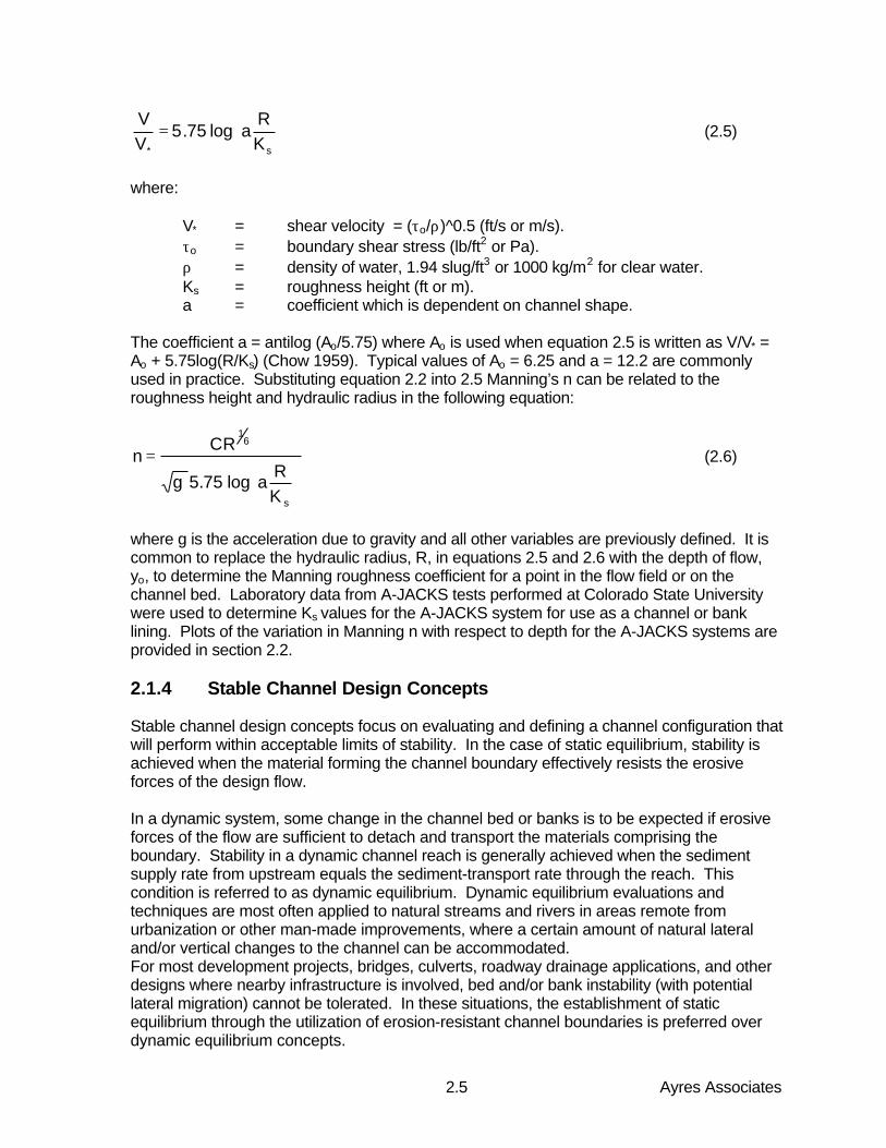
An assessment of the vertical velocity distribution is required to apply equation 2.9. Adistribution of shear stress based on the logarithmic velocity distribution in a straight reach ofa trapezoidal channel is shown in Figure 2.2a.
Ayres Associates2.7
Figure 2.2a. Shear stress distribution on the boundary of a trapezoidal channel in a straight reach.
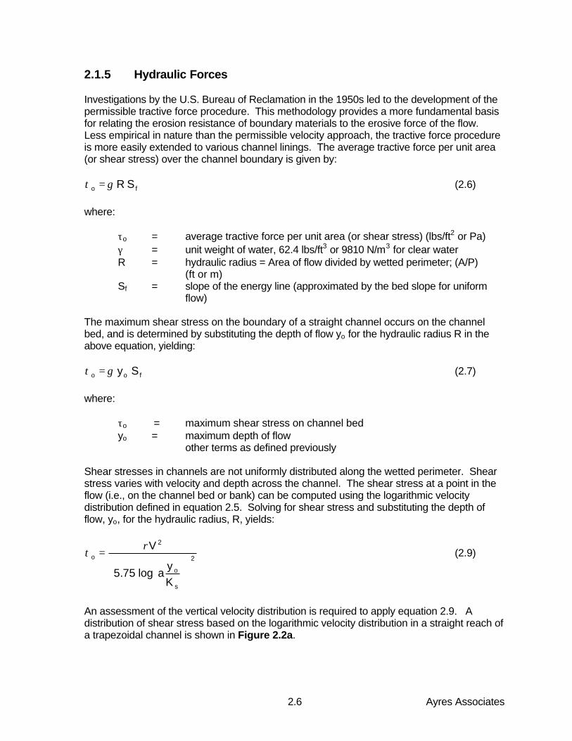
Flow around a bend creates secondary currents, which impose higher than normal shearstresses on the channel sides and bottom in localized areas, as shown in Figure 2.2b.
Figure 2.2b. Shear stress concentration areas in channel bend.
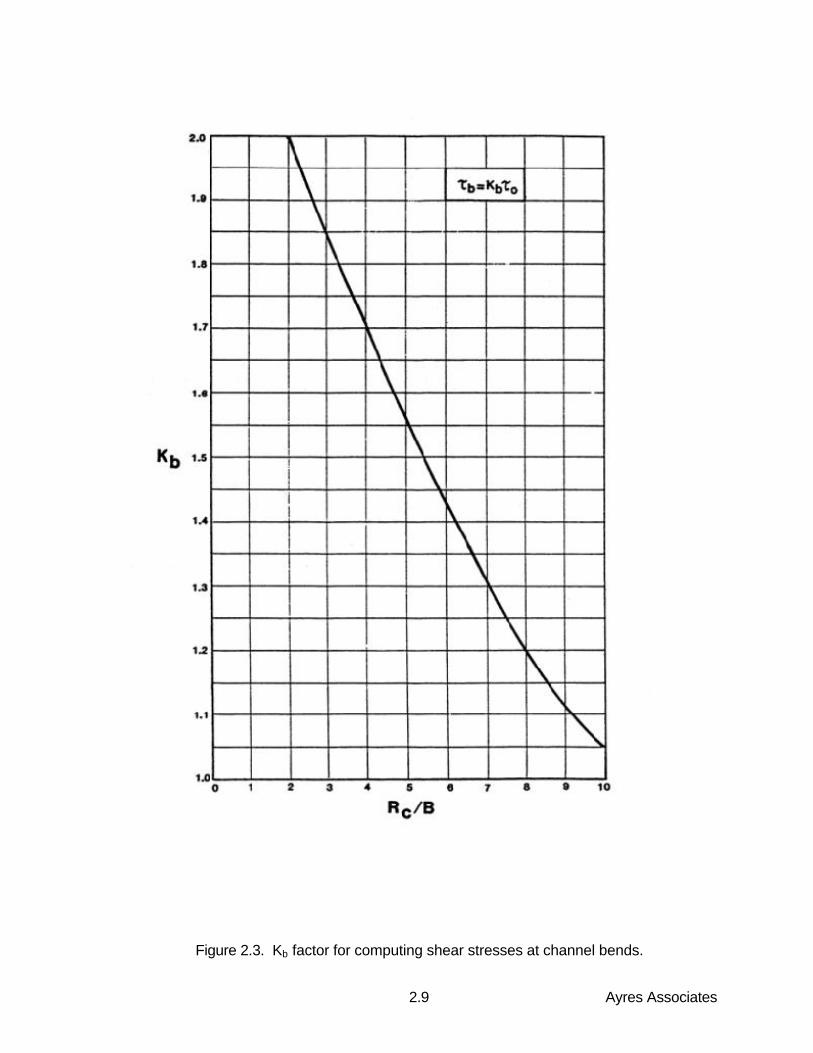
At the entrance to the bend, the maximum shear stress is located near the inside of thecurve. Near the exit of the bend, the zone of high shear stress is located near the outsideof the curve, and persists a distance Lp downstream from the point of tangency. The amountof increase in the shear stress due to a channel bend is related to the ratio of channelradius of curvature to the bottom width, Rc/b. The sharper the bend (small Rc), the higherthe amount of shear stress increase. The bend shear stress, τb, is expressed by the
Ayres Associates2.8
dimensionless factor, Kb, from Figure 2.3 multiplied by the maximum shear stress for anequivalent straight reach:
obb K ττ = (2.10)
It can be seen from Figure 2.4 that for relatively sharp bends, the effective shear stress cannearly double in magnitude compared to straight reaches.
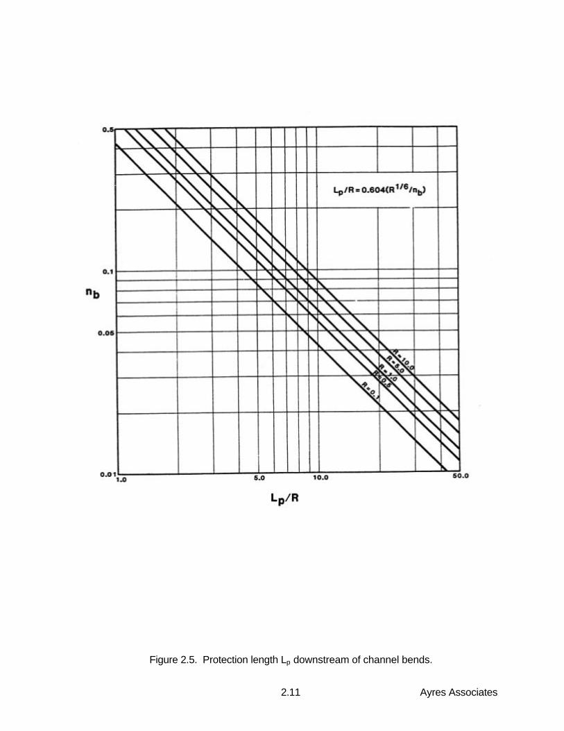
The distance Lp over which the high shear stresses persist downstream from the bend is afunction of the roughness of the boundary in the bend, nb, and the hydraulic radius of thechannel, R:
b
p
nR
RL 6
1604.0= (2.11)
Figure 2.4 provides the relationship of LP/R to nb, for typical ranges of the hydraulic radiusR. From this chart, it is seen that the effect of increasing the bend roughness serves todecrease the downstream distance over which the shear stress is influenced This is due tothe ability of a rougher boundary to more rapidly dissipate the secondary currents createdby the bend. Because the A-JACKS system provides more roughness than traditionalrevetments, this infers that the A-JACKS system can reduce the length of the high shearstress zone downstream of a bend.
2.1.6 Hydraulic Stability of A-JACKS Concrete Armor Units
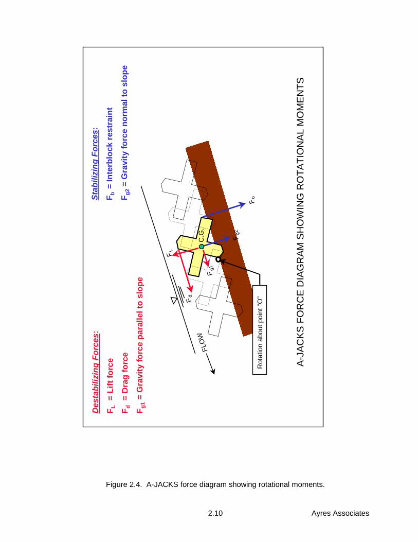
The stability of the A-JACKS is contingent on the system being installed in a continuousmatrix that spans the extent of the surface to be protected. Individual A-JACKS armor unitssurrounded by a matrix of identical blocks are subjected to the forces of lift and drag underthe action of flowing water. The lift force acts in a direction normal to the plane of the bed,and is typically comprised of the buoyant force and differential pressure across the matrixdue to local accelerations. The drag force acts in the direction of flow, and is comprised offrictional drag and form drag. The lift force and the drag force combine to produce anoverturning moment, which is resisted by the submerged weight of the interlocking matrix asshown in Figure 2.5.
2.1.7 Definition of Failure
Loss of "intimate contact" between the channel lining and the subgrade which it protects hasbeen identified as the primary indicator of incipient failure for many types of channelrevetment. Given the nature of revetment installation in typical channel applications, failuredue to slipping or sliding of the revetment matrix along the plane of the bed is remote. Theloss of intimate contact, therefore, is the result of overturning or uplift of a unit or group ofunits from the matrix. Incipient uplift occurs when the overturning moments equal resistingmoments about the downstream contact point of the unit. Once one or more armor unitsbecomes destabilized the system may continue to degrade if the flow conditions that causedinitial failure persist. The A-JACKS design criteria relies on their ability remain interlocked ina closely-packed matrix.
Ayres Associates2.9
Figure 2.3. Kb factor for computing shear stresses at channel bends.
Ayres Associates2.10
Figure 2.4. A-JACKS force diagram showing rotational moments.
FLO
WC
.G.
Fd
FL
Fg1
Fg2
Fb
Des
tabi
lizin
g Fo
rces
:
F L =
Lift
forc
e
F d =
Dra
g fo
rce
F g1 =
Gra
vity
forc
e pa
ralle
l to
slop
e
Stab
ilizi
ng F
orce
s :
F b =
Inte
rblo
ck re
stra
int
F g2 =
Gra
vity
forc
e no
rmal
to s
lope
Rot
atio
n ab
out p
oint
“O”
A-JA
CKS
FO
RC
E D
IAG
RAM
SH
OW
ING
RO
TATI
ON
AL M
OM
ENTS
Ayres Associates2.11
Figure 2.5. Protection length Lp downstream of channel bends.
Ayres Associates2.12
2.1.8 Hydraulic Stability - The Discrete Particle Method
The method for quantifying the hydraulic stability of an A-JACKS matrix utilizes the "discreteparticle" approach. Adapted to manufactured revetment systems, this approach is similar tothat introduced by Stevens (1968) for sizing rock riprap. The stability of A-JACKS isdependent on the interlocking characteristics of individual units to neighboring units in thematrix. The design analysis method compares the ratio of the overturning moments due touplift and tractive forces caused by the flow to the resisting moments due to weight andinterlock unique to the A-JACKS system. The ratio of resisting forces to tractive forces isknown as the factor of safety against failure as described by the following equation.
o
sc )K(FSτ
τ= (2.12)
where:
FS = factor of safetyτc = critical shear stress of the A-JACKS matrix (lb/ft2 or Pa)τo = the design hydraulic shear stress caused by the flow (lb/ft2 or Pa)Ks = side slope reduction factor
The resisting forces are dependent on the on the size and weight of an individual unit withinthe matrix, as well as the restraint provided by adjacent units. This method is calibrated tothe results obtained from laboratory model tests, and can be extended to larger A-JACKSunits through Froude-law scaling, providing the individual units are geometrically similar tothose tested.
2.1.9 Selection of Factor of Safety for Channel Revetments
It is the designer’s responsibility to determine the appropriate factor of safety to be used fora particular design. Some variables that affect the factor of safety are (1) the frequency ofthe design event, (2) risks associated with a failure of the project, (3) the uncertainty ofhydraulic values used in the design, and (4) uncertainties associated with the quality ofsubgrade preparation or revetment installation. Typically, a minimum factor of safetyagainst failure during the design hydrologic event of 1.2 is used for revetment design, withvalues of 3.0 or greater specified for areas of complex flow fields or geometric irregularities.Values of 5.0 or more may be used in cases where the consequences of failure are dire.
2.2 A-JACKS Hydraulic Performance Characteristics
2.2.1 General
A comprehensive physical model testing program of A-JACKS revetment in channel bedand bank lining applications was conducted by Colorado State University researchers atCSU’s Engineering Research Center in late 1998 and early 1999. The purpose of thelaboratory tests was to document the hydraulic characteristics and performance capability ofA-JACKS under various conditions of open-channel flow.
Ayres Associates2.13
Both 6-inch and 24-inch A-JACKS units were studied in a variety of flume environmentsunder controlled laboratory conditions. Three placement configurations were examined:random (loose), low density interlocked, and high density interlocked. From these studies, itwas determined that the high-density interlocked configuration resulted in the highest andmost consistent stability performance. This configuration forms the basis for the designprocedures developed in this chapter. A complete and detailed description of CSU’s testingprogram, data, observations and conclusions is provided in the CSU research documentsentitled, "A-JACKS Hydraulic Property Documentation" (Holmquist-Johnson, et al., February1999), and "A-JACKS Full-Scale Testing" (Thornton et al., February 1999).
Ayres Associates utilized the data from the CSU testing program to develop designparameters for the range of A-JACKS sizes commercially available for field installations (24,48, 72, and 96-inch tip-to-tip dimensions, corresponding to individual unit weights of 78,265, 2,120, and 5,020 pounds, respectively). The following sections present the theory andresults of this procedure.
2.2.2 Froude-Law Scaling
The results of the hydraulic tests on the 6-inch and 24-inch A-JACKS are extrapolated tothe larger sized units by means of hydraulic similitude using the dimensionless Froudenumber. This scaling techniques acknowledges that in open channel flow, the forces due togravity and inertia are of paramount importance. It also assumes that the effects of scalingon viscosity, pressure, and surface tension are either negligible or irrelevant to the stabilityof the prototype (i.e., field-scale) units.
All pertinent testing parameters may be defined in terms of the model scale ratio λ, definedin terms of a representative length unit as:
λ== Lm/Lp
where:
Lm = linear dimension in modelLp = linear dimension in prototype
For example, when testing a matrix of 6-inch A-JACKS and extrapolating the test results tothe 48-inch units, λ = (6")/(48"), or 1/8. In accordance with the principles of dimensionlessFroude number scaling, the pertinent hydraulic relationships are listed in Table 2.1.
2.2.3 Hydraulic Resistance: Manning's n
The A-JACKS high-density interlocked configuration was tested in CSU’s 2-foot indoorflume at two different bed slopes, 0.017 ft/ft and 0.04 ft/ft. At each bed slope, a series ofdischarges was run and Manning’s n was determined for each discharge from measureddata. The Manning's n value is related to the Darcy friction factor f by the relation
f = 116 n2y-1/3
where:
y = depth of flow
Ayres Associates2.14
Table 2.1. Hydraulic Relationships According to Froude Number Scaling.Parameter Dimensions Scale factor
Dimensional properties: Length L λArea L2 λ2
Volume L3 λ3
Kinematic properties: Time T λ1/2
Velocity L/T λ1/2
Discharge L3/T λ5/2
Dynamic properties: Mass M λ3
Force MLT-2 λ3
Shear stress ML-1T-2 λ
Resistance: Manning's n λ1/6
Note: Assumes undistorted model with fresh water used for both model and prototype.
An effective roughness height Ks can be calculated from this data by plotting the quantity f-
0.5 as a function of y/L, where L is the representative length of the tested A-JACKS unit, inthis case 6 inches. As seen in Figure 2.6, the CSU flume data closely matches the Prandtl-von Karman velocity distribution law (equation 2.6) using a best-fit Ks value of 5.7 times therepresentative length, or 34 inches, as determined by linear regression. Using Froude-lawscaling, the Manning n values for various sizes of A-JACKS prototype units are presented inFigure 2.7 as a function of depth of flow. Also on this figure are shown the Manning nvalues calculated from tests performed on the full-scale AJ-24 A-JACKS units (24 inchlength scale) at CSU’s outdoor flume. As seen from this figure, the full-scale tests provideindependent validation of the Froude-law scaling technique.
2.2.4 Critical Shear Stress
Due to limited discharge capacity and available bed slopes, indoor flume tests at CSU didnot result in destabilization of the 6-inch model A-JACKS in the high-density interlockedconfiguration. Therefore, additional testing on the 6-inch A-JACKS was performed in a 4foot wide outdoor flume at CSU’s Engineering Research Center. This flume is part of thetest facility referred to as the Tarbela flume in recognition of its original development anduse for dam and spillway studies to support the design of the Tarbela Dam, Pakistan’slargest water supply and hydroelectric facility.
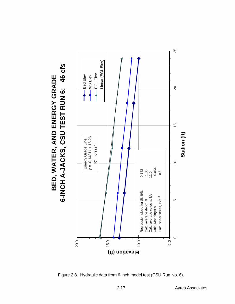
A-JACKS were placed in the high-density interlocked configuration along a 30-foot length offlume at a bed slope of 0.13 ft/ft (13 percent). Six tests were conducted at increasingdischarges, up to a maximum of 46 ft3/s during Test Run 6. An applied shear stress of 9.5lb/ft2 and a peak velocity of 11.0 ft/s were calculated from measured data on the 6-inch A-JACKS units at the highest discharge investigated. No movement of the A-JACKS wasobserved in any of these tests. A plot of bed elevation, water surface elevation, and energygrade line corresponding to Test Run 6 is provided in Figure 2.8.
Ayres Associates2.15
Figure 2.6. Roughness height Ks from 6-inch model tests.
Ro
ug
hn
ess
Hei
gh
t K s
CS
U F
lum
e d
ata:
6"
A-J
acks
, Hig
h-D
ensi
ty In
terl
ock
ed
0
0.51
1.52
2.5 0.
51
1.5
22.
53
3.5
y/L
1/f0.5
Bes
t fit
Ks
= 34
inch
es
Flum
e da
ta -
6 in
., hi
gh d
ensi
ty
Ayres Associates2.16
Figure 2.7. Recommended Manning's n values versus depth of flow.
A-J
acks
Man
nin
g n
val
ues
0.00
0.02
0.04
0.06
0.08
0.10
0.12
0.14
0.16
0.18
0.20
0.22
110
100
Dep
th (
ft)
Manning n
AJ-
24
AJ-
48
AJ-
96
550
AJ-
72
CS
U d
ata:
AJ-
24fu
ll-sc
ale
test
s
Ayres Associates2.17
Figure 2.8. Hydraulic data from 6-inch model test (CSU Run No. 6).
BE
D, W
AT
ER
, AN
D E
NE
RG
Y G
RA
DE
6-IN
CH
A-J
AC
KS
, CS
U T
ES
T R
UN
6:
46
cfs
Ene
rgy
Gra
de L
ine:
y =
-0.1
481x
+ 1
6.26
R
2 = 0
.992
4
5.0
10.0
15.0
20.0
05
1015
2025
Sta
tion
(ft
)
Elevation (ft)
Bed
Ele
v
WS
Ele
v
EG
L E
lev
Line
ar (E
GL
Ele
v)
Reg
ress
ion
slop
e fo
r Sf,
ft/ft
:
0.
148
C
alc.
ave
rage
dep
th, f
t
1.0
5
Cal
c. a
vera
ge v
eloc
ity, f
t/s
11.
0
Cal
c. M
anni
ng's
n
0.05
4
C
alc.
she
ar s
tres
s, lb
/ft2
9
.5
Ayres Associates2.18
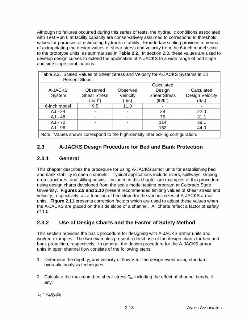
Although no failures occurred during this series of tests, the hydraulic conditions associatedwith Test Run 6 at facility capacity are conservatively assumed to correspond to thresholdvalues for purposes of estimating hydraulic stability. Froude-law scaling provides a meansof extrapolating the design values of shear stress and velocity from the 6-inch model scaleto the prototype units, as summarized in Table 2.2. In section 2.3, these values are used todevelop design curves to extend the application of A-JACKS to a wide range of bed slopeand side slope combinations.
Table 2.2. Scaled Values of Shear Stress and Velocity for A-JACKS Systems at 13 Percent Slope.
A-JACKS System
ObservedShear Stress
(lb/ft2)
ObservedVelocity
(ft/s)
CalculatedDesign
Shear Stress(lb/ft2)
CalculatedDesign Velocity
(ft/s)6-inch model 9.5 11.0 - -
AJ - 24 - - 38 22.0AJ - 48 - - 76 31.1AJ - 72 - - 114 38.1AJ - 96 - - 152 44.0
Note: Values shown correspond to the high-density interlocking configuration.
2.3 A-JACKS Design Procedure for Bed and Bank Protection
2.3.1 General
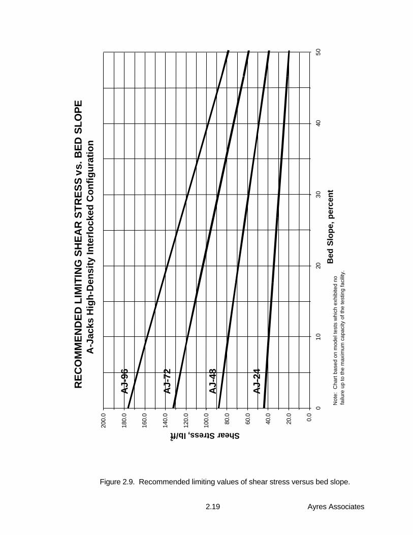
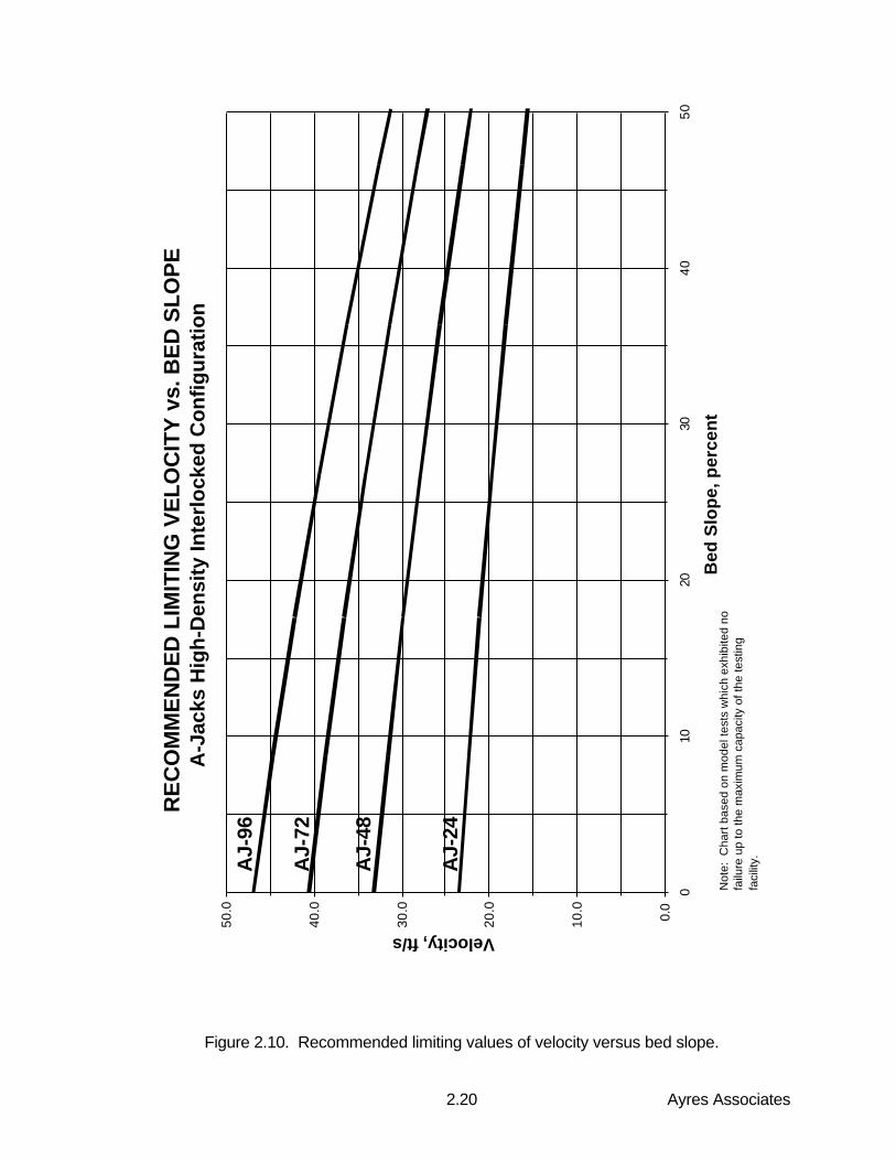
This chapter describes the procedure for using A-JACKS armor units for establishing bedand bank stability in open channels. Typical applications include rivers, spillways, slopingdrop structures, and stilling basins. Included in this chapter are examples of this procedureusing design charts developed from the scale model testing program at Colorado StateUniversity. Figures 2.9 and 2.10 present recommended limiting values of shear stress andvelocity, respectively, as a function of bed slope for the various sizes of A-JACKS armorunits. Figure 2.11 presents correction factors which are used to adjust these values whenthe A-JACKS are placed on the side slope of a channel. All charts reflect a factor of safetyof 1.0.
2.3.2 Use of Design Charts and the Factor of Safety Method
This section provides the basic procedure for designing with A-JACKS armor units andworked examples. The two examples present a direct use of the design charts for bed andbank protection, respectively. In general, the design procedure for the A-JACKS armorunits in open channel flow consists of the following steps:
1. Determine the depth y0 and velocity of flow V for the design event using standardhydraulic analysis techniques.
2. Calculate the maximum bed shear stress τ0, including the effect of channel bends, ifany:
τ0 = Kbγy0Sf
Ayres Associates2.19
Figure 2.9. Recommended limiting values of shear stress versus bed slope.
RE
CO
MM
EN
DE
D L
IMIT
ING
SH
EA
R S
TR
ES
S v
s. B
ED
SLO
PE
A-J
acks
Hig
h-D
ensi
ty In
terl
ock
ed C
on
fig
ura
tio
n
0.0
20.0
40.0
60.0
80.0
100.
0
120.
0
140.
0
160.
0
180.
0
200.
0
010
2030
4050
Bed
Slo
pe,
per
cen
t
Shear Stress, lb/ft2
AJ-
96
AJ-
72
AJ-
48
AJ-
24
Not
e: C
hart
bas
ed o
n m
odel
test
s w
hich
exh
ibite
d no
fa
ilure
up
to th
e m
axim
um c
apac
ity o
f the
test
ing
faci
lity.
Ayres Associates2.20
Figure 2.10. Recommended limiting values of velocity versus bed slope.
RE
CO
MM
EN
DE
D L
IMIT
ING
VE
LO
CIT
Y v
s. B
ED
SL
OP
EA
-Jac
ks H
igh
-Den
sity
Inte
rlo
cked
Co
nfig
ura
tion
0.0
10.0
20.0
30.0
40.0
50.0
010
2030
4050
Bed
Slo
pe,
per
cen
t
Velocity, ft/s
AJ-
96
AJ-
72
AJ-
48
AJ-
24
Not
e: C
hart
bas
ed o
n m
odel
test
s w
hich
exh
ibite
d no
fa
ilure
up
to th
e m
axim
um c
apac
ity o
f the
test
ing
faci
lity.
Ayres Associates2.21
Figure 2.11. Side slope reduction factors for channel bank applications.
SID
E S
LO
PE
RE
DU
CT
ION
FA
CT
OR
SA
-Jac
ks H
igh
-Den
sity
Inte
rlo
cked
Co
nfig
ura
tion
0.4
0.5
0.6
0.7
0.8
0.9
1.0
010
2030
4050
Sid
e sl
op
e, p
erce
nt
Reduction factor
Vel
ocity
red
uctio
n fa
ctor
She
ar s
tress
red
uctio
n fa
ctor
Ayres Associates2.22
where:
Kb = bend coefficient for shear stress (1.0 for straight channels)γ = unit weight of water, 62.4 lb/ft3y0 = depth of flow, ftSf = slope of energy grade line, ft/ft
3. Determine the limiting values of shear stress and velocity for the desired A-JACKSsystem from Figures 2.9 and 2.10, respectively, corresponding to the channel bed slope.
4. Multiply the limiting values of shear stress and velocity from Step 3 by the side slope
reduction factors found in Figure 2.11, corresponding to the channel side slope.
5. Calculate the safety factors for shear stress and velocity as the ratio of limiting designvalues to actual (project-specific) values as shown below:
Shear stress safety factor SFτ = τp(Kt)/τ0Velocity safety factor SFV = Vp(Kv)/V
where:
τp and Vp are limiting values of shear stress and velocity from Figures 2.9 and 2.10,respectively
Kt and Kv are side slope correction factors from Figure 2.11
Example 1:
Given: Sloping drop structure on the channel bed is to be formed of A-JACKS. Channelside slopes are lined with cast-in-place concrete.
100-year design discharge: Q = 500 ft3/s Slope of drop structure: S0 = 0.10 ft/ft (10 percent)
Channel bottom width: b = 20 ftChannel side slope: Z = 2H:1VRequired factor of safety: F.S. = 2.0
Solution:
Step 1
The determination of hydraulic conditions will be iterative, since the Manning n value for A-JACKS is highly dependent on depth. The solution procedure will evaluate the AJ-24 armorunits (24-inch length, 78 pounds per unit) and determine their factor of safety under thegiven conditions.
Trial 1: a. Assume depth of flow is 2 ftb. Determine Manning n of 0.14 for AJ-24c. Enter nomograph of Fig. 2.1 with Qn = 500 x 0.14 = 70d. From nomograph determine y0/b = 0.16e. Calculate y0 = 0.16 x bottom width = 0.16 x 20 = 3.2 feet
Ayres Associates2.23
Since the computed depth is greater than the depth we initially assumed, we will have tomake a second trial with a greater depth.
Trial 2: a. Assume depth of flow is 2.75 ftb. From Figure 2.1, determine Manning n of 0.105 for AJ-24c. Enter nomograph of Fig. 2.1 with Qn = 500 x 0.105 = 52.5d. From nomograph determine y0/b = 0.14e. Calculate y0 = 0.14 x bottom width = 0.14 x 20 = 2.8 feet
The calculated value of flow depth, 2.8 feet, is close enough to the assumed value of 2.75feet to allow continuation to the next step.
Step 2
Determine velocity and bed shear stress (including bend correction):
a. Velocity: V = Q/A = Q/y0(b+Zy0) = (500 ft3/s) / (71.7 ft2 ) = 7.0 ft/s
b. Bend coefficient: No bend in channel section, so Kb = 1.0
c. Maximum shear stress: τ0 = Kbγy0Sf = 1.0 x 62.4 lb/ft3 x 2.8 ft x 0.10 ft/ft
τ0 = 17.5 lb/ft2
Step 3
Determine the suitability of A-JACKS AJ-24 armor units:
Enter the charts, Figures 2.9 and 2.10, at a bed slope of 0.10 ft/ft (10 percent). Determinethe limiting values of shear stress and velocity for AJ-24 armor units on the channel bed:
τp (bed) = 40 lb/ft2
Vp (bed) = 22 ft/s
Since the A-JACKS will not be placed on the side slopes, no side slope corrections need tobe made.
Step 4
Determine the safety factors associated with shear stress and velocity:
F.S. (shear stress) = (τp) / (τactual) = (40 lb/ft2) / (17.5 lb/ft2) = 2.3F.S. (velocity) = (Vp) / (Vactual) = (22 ft/s) / (7.0 ft/s) = 3.1
Conclude that safety factors for both shear and velocity criteria exceed the required value of2.0 for this particular application, using A-JACKS AJ-24 armor units.
Ayres Associates2.24
Step 5
Summarize results for the A-JACKS AJ-24 system:
100-year discharge Q, ft3/s 500Bed slope, percent 10Bottom width b, ft 20Side slope Z (not lined with A-JACKS) 2H:1VManning's n 0.105Depth y, ft 2.8Velocity V, ft/s 7.0Shear stress τ0, lb/ft2 17.5Safety factor (shear stress) 2.3Safety factor (velocity) 3.1
Example 2:
Given: A wide natural channel is to have its banks stabilized with A-JACKS. The channelbed is to be left as a soft-bottom channel with an n-value of 0.035. The channel has asweeping bend with a radius of curvature Rc of 200 feet.
100-year design discharge: Q = 2,800 ft3/s Slope of drop structure: S0 = 0.012 ft/ft (1.2 percent)
Channel bottom width: b = 40 ftChannel side slope: Z = 4H:1VRequired factor of safety: F.S. = 1.5
Solution:
Step 1
The determination of hydraulic conditions will be straightforward, since the roughness of theA-JACKS along the banks will not appreciably affect the flow conditions of the soft-bottomchannel. The solution procedure will evaluate the AJ-24 armor units (24-inch length, 78pounds per unit) and determine their factor of safety under the given conditions.
a. Enter nomograph of Fig. 2.1 with Qn = 2,800 x 0.035 = 98b. From nomograph determine y0/b = 0.12c. Calculate y0 = 0.12 x bottom width = 0.12 x 40 = 4.8 feet
Step 2
Determine velocity and bed shear stress (including bend correction):
a. Velocity: V = Q/A = Q/y0(b+Zy0) = (2,800 ft3/s) / (284 ft2 ) = 9.9 ft/s
b. Bend coefficient: From Figure 2.3 with Rc/b = 200/40 = 5, find Kb = 1.55
c. Maximum shear stress: τ0 = Kbγy0Sf = 1.55 x 62.4 lb/ft3 x 4.8 ft x 0.012 ft/ft
τ0 = 5.6 lb/ft2
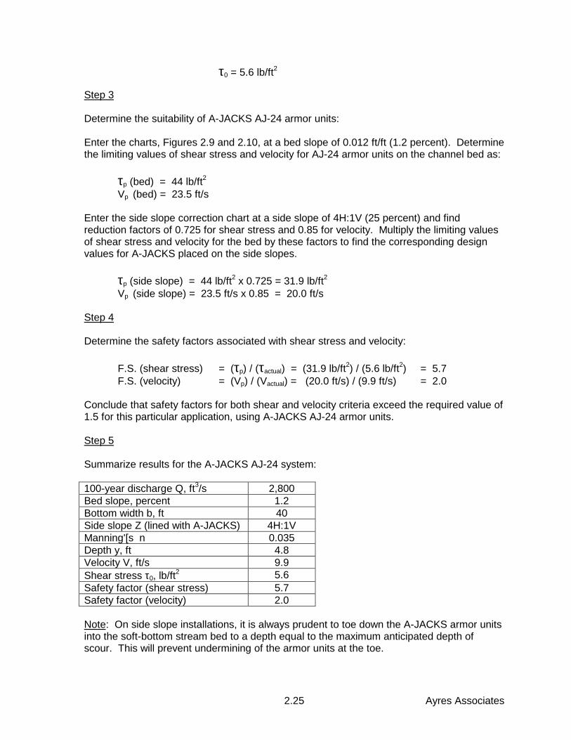
Ayres Associates2.25
τ0 = 5.6 lb/ft2
Step 3
Determine the suitability of A-JACKS AJ-24 armor units:
Enter the charts, Figures 2.9 and 2.10, at a bed slope of 0.012 ft/ft (1.2 percent). Determinethe limiting values of shear stress and velocity for AJ-24 armor units on the channel bed as:
τp (bed) = 44 lb/ft2
Vp (bed) = 23.5 ft/s
Enter the side slope correction chart at a side slope of 4H:1V (25 percent) and findreduction factors of 0.725 for shear stress and 0.85 for velocity. Multiply the limiting valuesof shear stress and velocity for the bed by these factors to find the corresponding designvalues for A-JACKS placed on the side slopes.
τp (side slope) = 44 lb/ft2 x 0.725 = 31.9 lb/ft2
Vp (side slope) = 23.5 ft/s x 0.85 = 20.0 ft/s
Step 4
Determine the safety factors associated with shear stress and velocity:
F.S. (shear stress) = (τp) / (τactual) = (31.9 lb/ft2) / (5.6 lb/ft2) = 5.7F.S. (velocity) = (Vp) / (Vactual) = (20.0 ft/s) / (9.9 ft/s) = 2.0
Conclude that safety factors for both shear and velocity criteria exceed the required value of1.5 for this particular application, using A-JACKS AJ-24 armor units.
Step 5
Summarize results for the A-JACKS AJ-24 system:
100-year discharge Q, ft3/s 2,800Bed slope, percent 1.2Bottom width b, ft 40Side slope Z (lined with A-JACKS) 4H:1VManning'[s n 0.035Depth y, ft 4.8Velocity V, ft/s 9.9Shear stress τ0, lb/ft2 5.6Safety factor (shear stress) 5.7Safety factor (velocity) 2.0
Note: On side slope installations, it is always prudent to toe down the A-JACKS armor unitsinto the soft-bottom stream bed to a depth equal to the maximum anticipated depth ofscour. This will prevent undermining of the armor units at the toe.
Ayres Associates2.26
2.3.3 Bedding Considerations
When using A-JACKS on channel beds or banks where the native soil is fine enough to bepulled through the voids between the armor units, the system should be placed on ageotextile or granular bedding material which has been selected for compatibility with thenative soils. The bedding must retain the soil particles of the subgrade while allowing waterto freely infiltrate and exfiltrate through the system for the entire service life of the structureunder the site-specific design gradients anticipated. When using a geotextile, the apparentopening size (AOS) and its permeability are therefore the primary design characteristicsconsidered in selecting the appropriate fabric for compatibility with the soil subgrade.Additionally, protection against long-term potential for clogging involves the fabric’s percentopen area (woven geotextiles) or porosity (nonwoven geotextiles).
The bedding stone or geotextile filter should be selected based on the site-specific soilcharacteristics, physical boundary conditions, and hydraulic conditions. For erosionprotection using A-JACKS armor units, the bedding layer typically governs the passage ofwater through the protection system, since the block system itself maintains a relativelylarge drainage area as a result of voids between the legs of the individual armor units. Thepurpose of the bedding layer is to prevent soil loss due to piping or washout through thearmor units, while preventing excessive hydraulic uplift pressures from developing beneaththe system. In some cases, select imported granular fill can be used in conjunction with ageotextile. This section does not apply to other types of geosynthetic soil erosion control orstabilizing systems, such as erosion control revegetation mats, turf reinforcement mats, orgeogrids.
If placement of a geotextile below the waterline is anticipated, a bedding layer of suitably-sized crushed rock, large gravel, or small cobbles may be placed directly on top of thegeotextile prior to installing the block system. The bedding layer serves both as ballast forthe geotextile and as a means of achieving closer tolerances to the design lines and grades,particularly when an irregular surface exists.
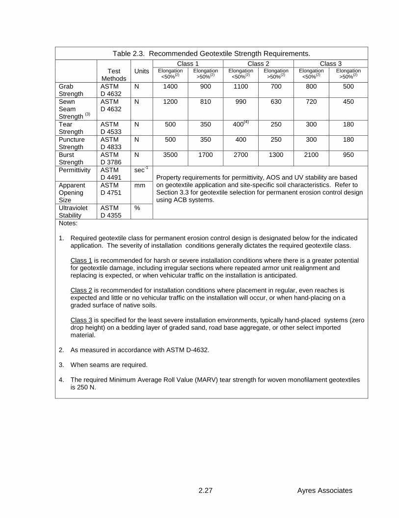
Appropriate geotextile strength requirements, corresponding to installation survivabilityconsiderations, are recommended in Table 2.3. In general, design guidelines recommendthat the geotextile exhibit a permeability at least 10 times greater than the underlyingsubsoil. In addition, a typical requirement is that the Apparent Opening Size (AOS) of thegeotextile should be selected to retain at least 30 percent, but not more than 70 percent, ofthe particle sizes present. However, defining specific geotextile selection and designmethods, and the resulting property values for geotextiles in this application, is beyond thescope of this manual. Other sources of information and guidance for this application havebeen developed which are referenced below:
1. TC Mirafi, 1998. "Geotextile Filter Design Manual." Prepared by GeosyntecConsultants, Norcross, Georgia.
2. Industrial Fabrics Association, 1990. "A Design Primer: Geotextiles and Related
Materials." St. Paul, Minnesota. 3. American Association of State Highway Transportation Officials (AASHTO), 1995.
"Standard Specification for Geotextiles." AASHTO Designation M 288-96 DRAFT.February.
Ayres Associates2.27
Table 2.3. Recommended Geotextile Strength Requirements.Class 1 Class 2 Class 3
TestMethods
Units Elongation<50%(2)
Elongation>50%(2)
Elongation<50%(2)
Elongation>50%(2)
Elongation<50%(2)
Elongation>50%(2)
GrabStrength
ASTMD 4632
N 1400 900 1100 700 800 500
SewnSeamStrength (3)
ASTMD 4632
N 1200 810 990 630 720 450
TearStrength
ASTMD 4533
N 500 350 400(4) 250 300 180
PunctureStrength
ASTMD 4833
N 500 350 400 250 300 180
BurstStrength
ASTMD 3786
N 3500 1700 2700 1300 2100 950
Permittivity ASTMD 4491
sec-1
ApparentOpeningSize
ASTMD 4751
mm
UltravioletStability
ASTMD 4355
%
Property requirements for permittivity, AOS and UV stability are basedon geotextile application and site-specific soil characteristics. Refer toSection 3.3 for geotextile selection for permanent erosion control designusing ACB systems.
Notes:
1. Required geotextile class for permanent erosion control design is designated below for the indicatedapplication. The severity of installation conditions generally dictates the required geotextile class.
Class 1 is recommended for harsh or severe installation conditions where there is a greater potentialfor geotextile damage, including irregular sections where repeated armor unit realignment andreplacing is expected, or when vehicular traffic on the installation is anticipated.
Class 2 is recommended for installation conditions where placement in regular, even reaches isexpected and little or no vehicular traffic on the installation will occur, or when hand-placing on agraded surface of native soils.
Class 3 is specified for the least severe installation environments, typically hand-placed systems (zerodrop height) on a bedding layer of graded sand, road base aggregate, or other select importedmaterial.
2. As measured in accordance with ASTM D-4632. 3. When seams are required. 4. The required Minimum Average Roll Value (MARV) tear strength for woven monofilament geotextiles
is 250 N.
Ayres Associates2.28
2.4 A-JACKS Installation Guidelines
Recommended guidelines for the installation of A-JACKS armor units in channel bed andbank applications are provided in the following sections and accompanying figures.
2.4.1 Subgrade Preparation
Subgrade soil should be prepared to the lines, grades, and cross sections shown on thecontract drawings. Termination trenches and transitions between slopes or slopes andembankment crests, benches, berms, and toes should be shaped and uniformly graded tofacilitate the development of intimate contact between the A-JACKS system and theunderlying grade.
Subgrade soil should be approved by the Engineer to confirm that the actual subgrade soilconditions meet or exceed the required material standards and conform to the designcalculations and assumptions. Soils not meeting the required standards should be removedand replaced with acceptable material.
Care should be exercised so as not to excavate below the grades shown on the contractdrawings, unless directed by the Engineer to remove unsatisfactory materials, and anyexcessive excavation should be filled with approved backfill material and compacted.Where it is impractical, in the opinion of the Engineer, to dewater the area to be filled, over-excavations should be backfilled with crushed rock or stone conforming to the grading andquality requirements of 19 mm (3/4 inch) maximum size coarse aggregate for concrete.
The areas above the waterline which are to receive the A-JACKS system should be gradedto a smooth surface to ensure that intimate contact is achieved between the subgradesurface and the bedding layer (granular materials and/or geotextile), and between thebedding layer and the bottom surface of the A-JACKS system. Unsatisfactory soils andsoils having a natural in-place moisture content in excess of 40 percent, and soils containingroots, sod, brush, or other organic materials, should be removed, backfilled with selectmaterial, and compacted. The subgrade should be uniformly compacted to a minimum of95 percent of Standard Proctor density (ASTM D-698). Should the subgrade surface forany reason become rough, corrugated, uneven, textured, or traffic marked to the extent thatvoids beneath the armor system are created, such unsatisfactory portion should bescarified, reworked, recompacted, or replaced as directed by the Engineer.
Excavation of the subgrade, above the water line, should not be more than 100 mm (4inches) below the grade indicated on the contract drawings. Excavation of the subgradebelow the water line should not be more than 200 mm (8 inches) below the grade indicatedon the contract drawings. Where such areas are below the allowable grades, they shouldbe brought to grade by placing thin layers of select material and compacted. Where suchareas are above the allowable grades they should be brought to grade by removing materialor reworking existing material and compacting as directed by the Engineer.Immediately prior to placing the bedding and A-JACKS system, the prepared subgradeshould be inspected and approved by the Engineer.
Ayres Associates2.29
2.4.2 Placement of Geotextile
When a geotextile underlayer is used, the geotextile should be placed directly on theprepared area, in intimate contact with the subgrade, and free of folds or wrinkles. Thegeotextile shall be placed in such a manner that placement of the overlying A-JACKSsystem will not excessively stretch or tear the geotextile. After geotextile placement, thework area should not be disturbed so as to result is a loss of intimate contact between thearmor units and the geotextile, or between the geotextile and the subgrade. The geotextileshould not be left exposed longer than the manufacturer’s recommendation to minimizedamage potential due to ultraviolet radiation.
The geotextile should be placed so that the upstream strips of fabric overlap downstreamstrips, and so that upslope strips overlap downslope strips. Overlaps should be in thedirection of flow wherever possible. The longitudinal and transverse joints should beoverlapped at least 1m (3 ft.) for below-water installations, and at least half that amount fordry installations. If a sewn seam is to be used for the seaming of the geotextile, the threadused shall consist of high strength polypropylene or polyester and shall be resistant toultraviolet radiation. The geotextile should extend at least 0.3m (1 ft.) beyond the top, toe,and side termination points of the revetment. If necessary to expedite construction and tomaintain the recommended overlaps, 450 mm (18 in.) anchoring pins and/or 11gauge, 6"x1"U-staples may be used.
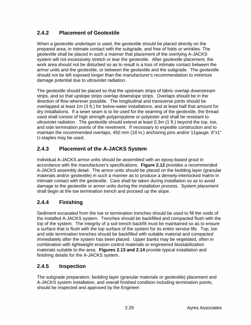
2.4.3 Placement of the A-JACKS System
Individual A-JACKS armor units should be assembled with an epoxy-based grout inaccordance with the manufacturer’s specifications. Figure 2.12 provides a recommendedA-JACKS assembly detail. The armor units should be placed on the bedding layer (granularmaterials and/or geotextile) in such a manner as to produce a densely-interlocked matrix inintimate contact with the geotextile. Care shall be taken during installation so as to avoiddamage to the geotextile or armor units during the installation process. System placementshall begin at the toe termination trench and proceed up the slope.
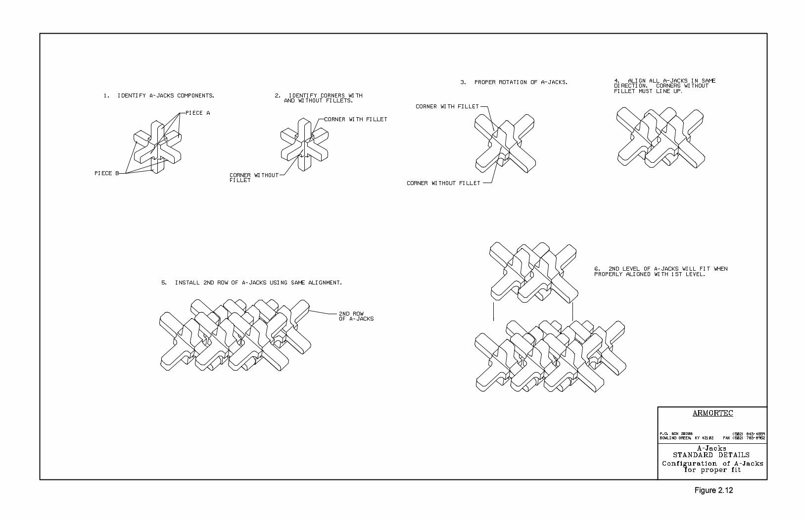
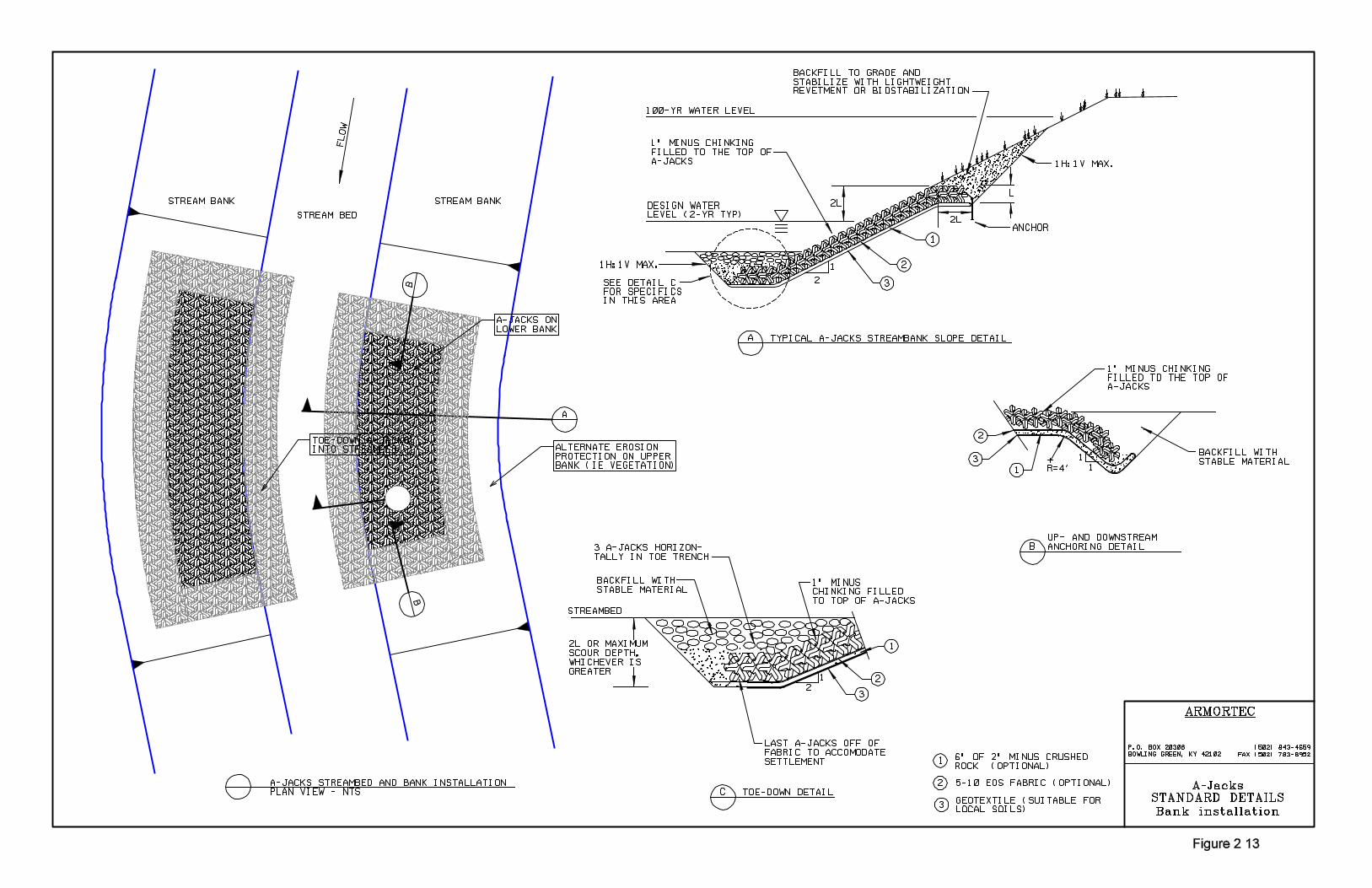
2.4.4 Finishing
Sediment excavated from the toe or termination trenches should be used to fill the voids ofthe installed A-JACKS system. Trenches should be backfilled and compacted flush with thetop of the system. The integrity of a soil trench backfill must be maintained so as to ensurea surface that is flush with the top surface of the system for its entire service life. Top, toeand side termination trenches should be backfilled with suitable material and compactedimmediately after the system has been placed. Upper banks may be vegetated, often incombination with lightweight erosion control materials or engineered biostabilizationmaterials suitable to the area. Figures 2.13 and 2.14 provide typical installation andfinishing details for the A-JACKS system.
2.4.5 Inspection
The subgrade preparation, bedding layer (granular materials or geotextile) placement andA-JACKS system installation, and overall finished condition including termination points,should be inspected and approved by the Engineer.
Ayres Associates3.1
3. PIER SCOUR APPLICATIONS
The use of A-JACKS for pier scour applications requires an understanding of local scourprocesses. A review of the fundamentals is presented to provide the designer with thetheory behind the development of design parameters. Specific design parameters for A-JACKS are presented to facilitate the selection of appropriate sizes of armor units for pierscour applications.
3.1 Mechanics of Pier Scour
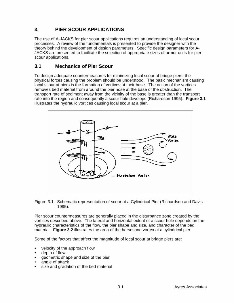
To design adequate countermeasures for minimizing local scour at bridge piers, thephysical forces causing the problem should be understood. The basic mechanism causinglocal scour at piers is the formation of vortices at their base. The action of the vorticesremoves bed material from around the pier nose at the base of the obstruction. Thetransport rate of sediment away from the vicinity of the base is greater than the transportrate into the region and consequently a scour hole develops (Richardson 1995). Figure 3.1illustrates the hydraulic vortices causing local scour at a pier.
Figure 3.1. Schematic representation of scour at a Cylindrical Pier (Richardson and Davis 1995).
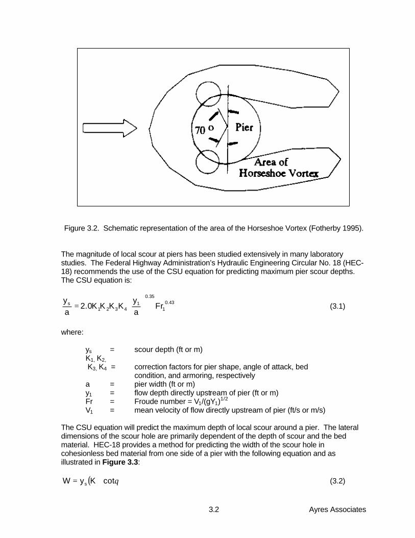
Pier scour countermeasures are generally placed in the disturbance zone created by thevortices described above. The lateral and horizontal extent of a scour hole depends on thehydraulic characteristics of the flow, the pier shape and size, and character of the bedmaterial. Figure 3.2 illustrates the area of the horseshoe vortex at a cylindrical pier.
Some of the factors that affect the magnitude of local scour at bridge piers are:
• velocity of the approach flow• depth of flow• geometric shape and size of the pier• angle of attack• size and gradation of the bed material
Ayres Associates3.2
Figure 3.2. Schematic representation of the area of the Horseshoe Vortex (Fotherby 1995).
The magnitude of local scour at piers has been studied extensively in many laboratorystudies. The Federal Highway Administration’s Hydraulic Engineering Circular No. 18 (HEC-18) recommends the use of the CSU equation for predicting maximum pier scour depths.The CSU equation is:
43.01
35.01
4321s Fr
ay
KKKK0.2ay
= (3.1)
where:
ys = scour depth (ft or m)K1, K2, K3, K4 = correction factors for pier shape, angle of attack, bed
condition, and armoring, respectivelya = pier width (ft or m)y1 = flow depth directly upstream of pier (ft or m)Fr = Froude number = V1/(gY1)1/2
V1 = mean velocity of flow directly upstream of pier (ft/s or m/s)
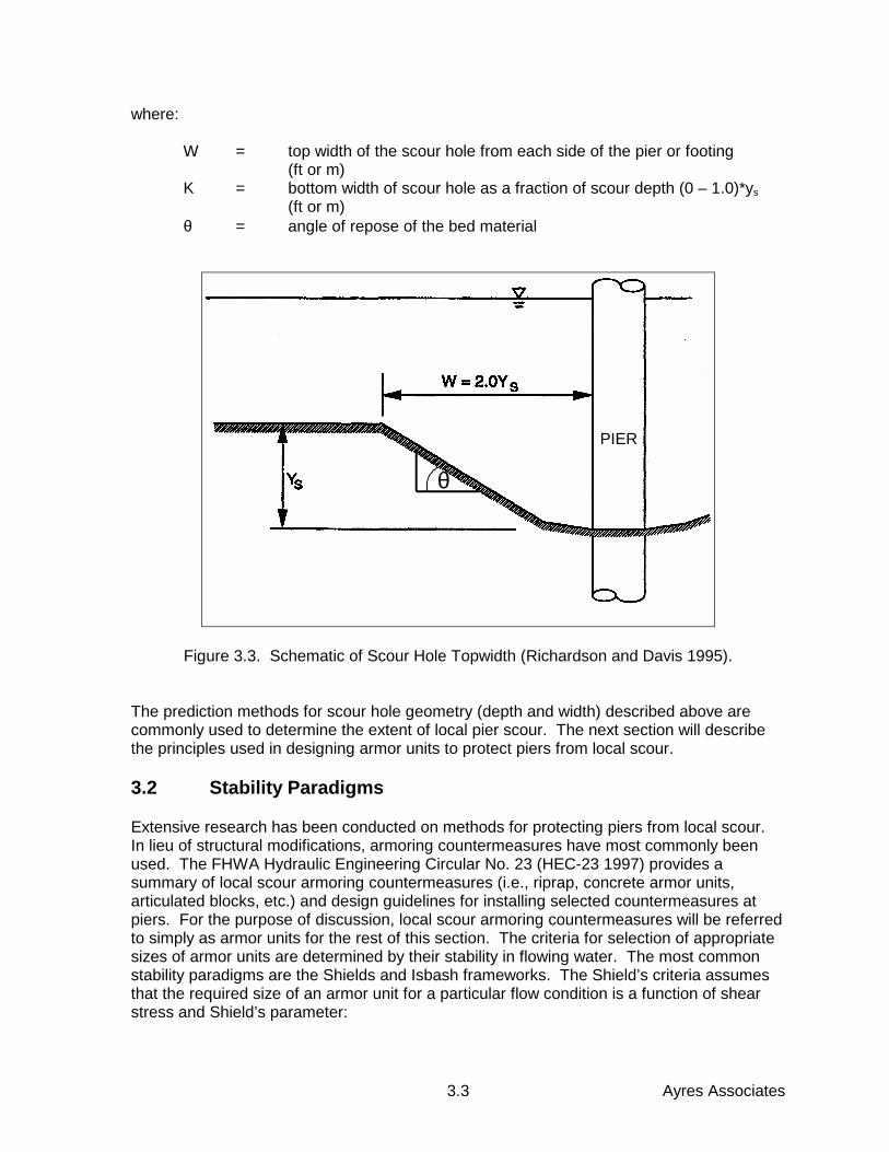
The CSU equation will predict the maximum depth of local scour around a pier. The lateraldimensions of the scour hole are primarily dependent of the depth of scour and the bedmaterial. HEC-18 provides a method for predicting the width of the scour hole incohesionless bed material from one side of a pier with the following equation and asillustrated in Figure 3.3:
( )θcotKyW s += (3.2)
70o
Pier
Area of HorseshoeVortex
Ayres Associates3.3
where:
W = top width of the scour hole from each side of the pier or footing(ft or m)
K = bottom width of scour hole as a fraction of scour depth (0 – 1.0)*ys(ft or m)
θ = angle of repose of the bed material
θ
Figure 3.3. Schematic of Scour Hole Topwidth (Richardson and Davis 1995).
The prediction methods for scour hole geometry (depth and width) described above arecommonly used to determine the extent of local pier scour. The next section will describethe principles used in designing armor units to protect piers from local scour.
3.2 Stability Paradigms
Extensive research has been conducted on methods for protecting piers from local scour.In lieu of structural modifications, armoring countermeasures have most commonly beenused. The FHWA Hydraulic Engineering Circular No. 23 (HEC-23 1997) provides asummary of local scour armoring countermeasures (i.e., riprap, concrete armor units,articulated blocks, etc.) and design guidelines for installing selected countermeasures atpiers. For the purpose of discussion, local scour armoring countermeasures will be referredto simply as armor units for the rest of this section. The criteria for selection of appropriatesizes of armor units are determined by their stability in flowing water. The most commonstability paradigms are the Shields and Isbash frameworks. The Shield’s criteria assumesthat the required size of an armor unit for a particular flow condition is a function of shearstress and Shield’s parameter:
PIER
Ayres Associates3.4
( )SP1SgD
gw
cu −
=ρ
τ(3.3)
where:
Du = equivalent spherical diameter of stone (ft or m)τc = shear stress required to move a particle (lb/ft2 or Pa)ρw = density of water (slug/ft3 or kg/m3)g = gravitational acceleration (ft/s2 or m/s2)Sg = specific gravity of the particleSP = Shields parameter which is a function of the flow conditions
The equivalent spherical diameter, Du, represents diameter of a sphere with the samevolume as the armor unit. When rock is used Du represents the D50 of the materialgradation. The difficulty in applying the Shield’s relationship to local scour countermeasuresis in determining a representative shear stress. Therefore, methods which incorporatevelocity (a variable which can be directly measured) are more commonly used to select localscour countermeasures. The Isbash approach relates particle stability to velocity and astability number, N:
( )N1SgVDg
2c
u −= (3.4)
where:
V = velocity acting on the stone required to initiate movement (ft/s orm/s)
N = stability number = 2E2 (1.5 for loose particles and 2.9 for seatedparticles)
E = Isbash’s coefficient (0.86 for loose particles and 1.2 for seatedparticles)
The stability number N and Isbash coefficient E are indicative of the shape and interlockingcharacteristics of the particular armor units. The Isbash and Shields relations weredeveloped for unobstructed flow conditions; therefore, these relationships requireadjustments for application to flow fields at piers. Normally, the approach velocity is usedwith a correction factor for the acceleration around a pier. The HEC-18 equation fordesigning riprap at piers uses the Isbash equation with a stability number of 2.9 and acorrection factor of 1.5 applied to the approach velocity for round nose piers. Theassumption is that the velocity at the base of the pier is approximately 1.5 times the meanvelocity of the approach velocity to the pier.
Investigators, including but not limited to Quazi and Peterson (1973), Neill (1975), Parola(1993), Bertoldi (1995), and Fotherby (1995) made contributions to the Isbash frameworkconsidering the effects of bridge piers on the stability of armor units. The later researchconsiders the effect of pier width and flow depth on the stability number.
Ayres Associates3.5
The foregoing developments have concentrated on the size, shape, and weight of individualarmor units, whether randomly placed or in stacked or interlocked configurations. However,the basic construction element of A-JACKS for pier scour applications is a "module"comprised of 14 individual A-JACKS banded together in a densely-interlocked cluster,described as a 5x4x5 module. The banded module thus forms the individual designelement. Figures 3.4a and 3.4b illustrate the concept.
In late 1998 and early 1999, a series of 54 tests of 6-inch model scale A-JACKS wasconducted at Colorado State University to examine their effectiveness in pier scourapplications. This program is described in detail in CSU’s test report entitled, "LaboratoryTesting of A-JACKS Units for Inland Applications: Pier Scour Protection Testing" (Thorntonet al., February 1999).
The CSU tests were conducted in an 8-foot wide indoor flume with a sand bed, andexamined a variety of conditions, including no protection (baseline conditions), banded5x4x5 modules arrayed in several different configurations, and individual (unbanded) A-JACKS armor units. Both round and square piers were used in the program. The resultsindicated that, when used in combination with a bedding layer (either granular beddingstone or a properly selected geotextile), the A-JACKS 5x4x5 modules reduced scour at thepier from 70 percent to more than 95 percent (scour depths were from 30 percent to lessthan 5 percent of that in the unprotected baseline condition).
Hydraulic stability of a 5x4x5 A-JACKS module can be estimated by setting the overturningmoment due to the total drag force equal to the resisting moment due to the submergedweight of the 5x4x5 module:
FdHd = WsLw (3.5)
where:
Fd = drag force, equal to 0.5CdρAV2, lbCd = drag coefficient (dimensionless)ρ = unit weight of water, 1.94 slugs/ft3A = frontal area of 5x4x5 A-JACKS module, ft2V = flow velocity immediately upstream of 5x4x5 A-JACKS module, ft/sHd = moment arm through which the drag force acts, ftWs = submerged weight of 5x4x5 A-JACKS module, lbLw = moment arm though which the submerged weight acts, ft
As a first estimate, the coefficient of drag Cd on a 5x4x5 A-JACKS module can be assumedto be similar to that of a disc oriented normal to the flow velocity, with flow occurring overthe top and around the sides. This value is approximately 1.2 (Vennard and Street 1975).A conservative estimate for the location of the drag force would place it at the full height ofthe module, providing the greatest moment arm for overturning.
In July 1999, Ayres Associates conducted an additional series of 5 tests at CSU in a steep(13 percent slope), fixed-bed flume. The purpose of these tests was to determine thehydraulic stability of the 5x4x5 A-JACKS modules in a typical pier scour configuration.Discharge was gradually increased until overturning of the module was achieved. Bothsubmerged and unsubmerged conditions were examined (Figures 3.5a and 3.5b).
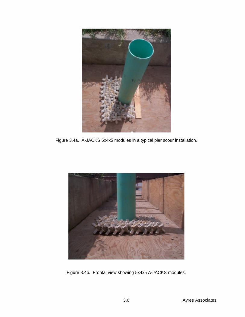
Ayres Associates3.6
Figure 3.4a. A-JACKS 5x4x5 modules in a typical pier scour installation.
Figure 3.4b. Frontal view showing 5x4x5 A-JACKS modules.
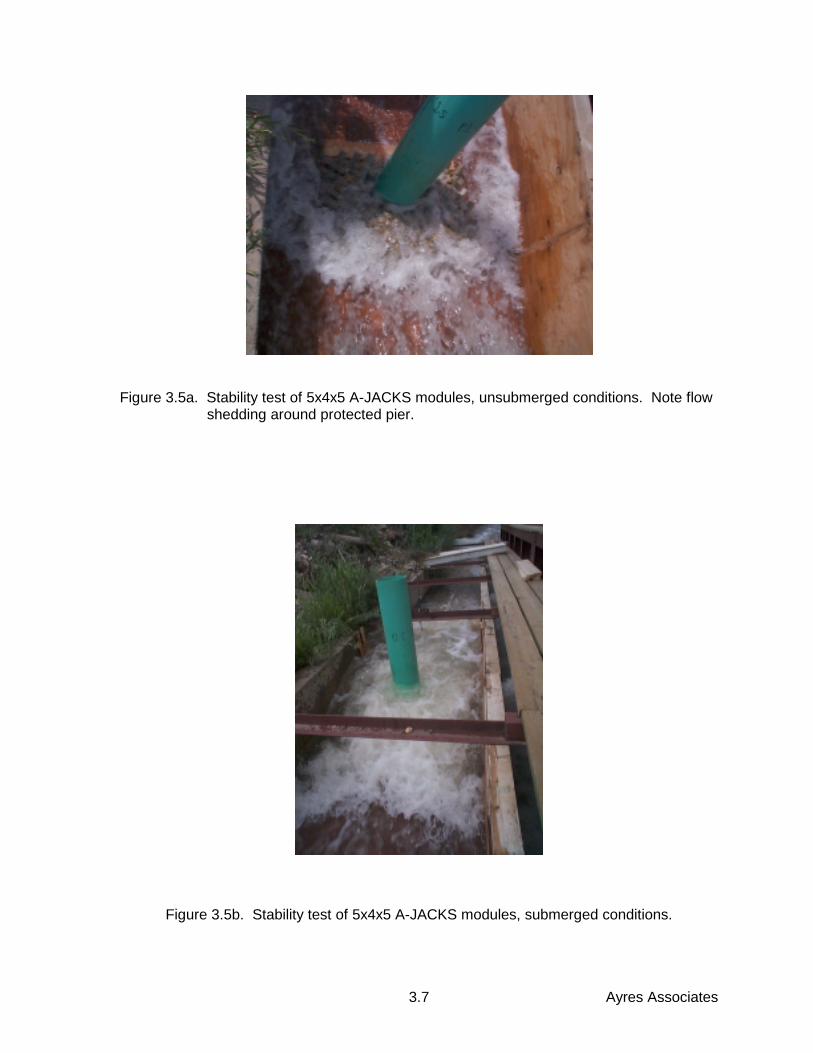
Ayres Associates3.7
Figure 3.5a. Stability test of 5x4x5 A-JACKS modules, unsubmerged conditions. Note flow shedding around protected pier.
Figure 3.5b. Stability test of 5x4x5 A-JACKS modules, submerged conditions.
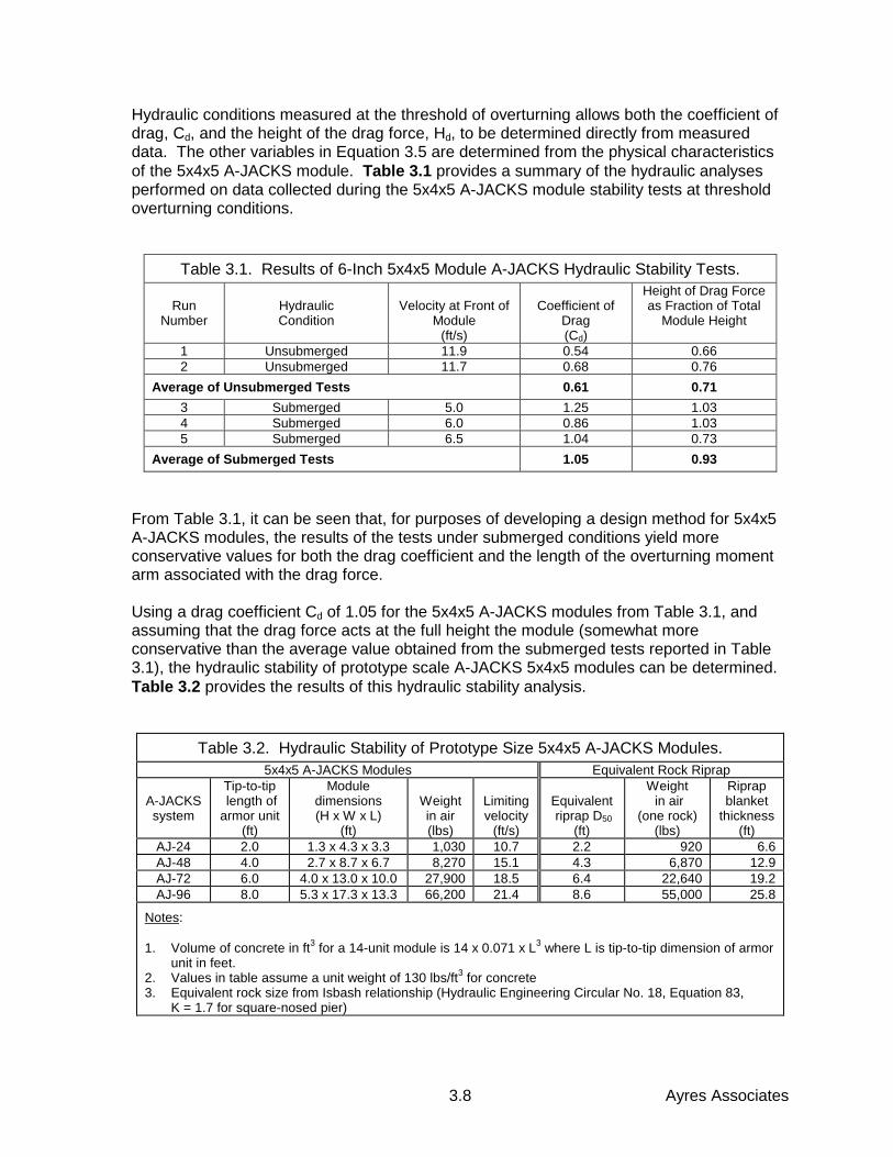
Ayres Associates3.8
Hydraulic conditions measured at the threshold of overturning allows both the coefficient ofdrag, Cd, and the height of the drag force, Hd, to be determined directly from measureddata. The other variables in Equation 3.5 are determined from the physical characteristicsof the 5x4x5 A-JACKS module. Table 3.1 provides a summary of the hydraulic analysesperformed on data collected during the 5x4x5 A-JACKS module stability tests at thresholdoverturning conditions.
Table 3.1. Results of 6-Inch 5x4x5 Module A-JACKS Hydraulic Stability Tests.
RunNumber
HydraulicCondition
Velocity at Front ofModule
(ft/s)
Coefficient ofDrag(Cd)
Height of Drag Forceas Fraction of Total
Module Height
1 Unsubmerged 11.9 0.54 0.662 Unsubmerged 11.7 0.68 0.76
Average of Unsubmerged Tests 0.61 0.713 Submerged 5.0 1.25 1.034 Submerged 6.0 0.86 1.035 Submerged 6.5 1.04 0.73
Average of Submerged Tests 1.05 0.93
From Table 3.1, it can be seen that, for purposes of developing a design method for 5x4x5A-JACKS modules, the results of the tests under submerged conditions yield moreconservative values for both the drag coefficient and the length of the overturning momentarm associated with the drag force.
Using a drag coefficient Cd of 1.05 for the 5x4x5 A-JACKS modules from Table 3.1, andassuming that the drag force acts at the full height the module (somewhat moreconservative than the average value obtained from the submerged tests reported in Table3.1), the hydraulic stability of prototype scale A-JACKS 5x4x5 modules can be determined.Table 3.2 provides the results of this hydraulic stability analysis.
Table 3.2. Hydraulic Stability of Prototype Size 5x4x5 A-JACKS Modules.5x4x5 A-JACKS Modules Equivalent Rock Riprap
A-JACKSsystem
Tip-to-tip length ofarmor unit
(ft)
Moduledimensions(H x W x L)
(ft)
Weightin air(lbs)
Limitingvelocity
(ft/s)
Equivalent riprap D50
(ft)
Weight in air
(one rock)(lbs)
Riprapblanket
thickness(ft)
AJ-24 2.0 1.3 x 4.3 x 3.3 1,030 10.7 2.2 920 6.6AJ-48 4.0 2.7 x 8.7 x 6.7 8,270 15.1 4.3 6,870 12.9AJ-72 6.0 4.0 x 13.0 x 10.0 27,900 18.5 6.4 22,640 19.2AJ-96 8.0 5.3 x 17.3 x 13.3 66,200 21.4 8.6 55,000 25.8
Notes:
1. Volume of concrete in ft3 for a 14-unit module is 14 x 0.071 x L3 where L is tip-to-tip dimension of armorunit in feet.
2. Values in table assume a unit weight of 130 lbs/ft3 for concrete3. Equivalent rock size from Isbash relationship (Hydraulic Engineering Circular No. 18, Equation 83,
K = 1.7 for square-nosed pier)
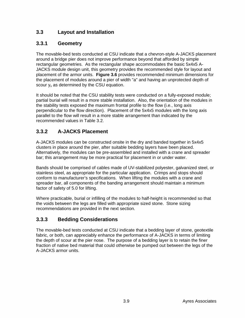
Ayres Associates3.9
3.3 Layout and Installation
3.3.1 Geometry
The movable-bed tests conducted at CSU indicate that a chevron-style A-JACKS placementaround a bridge pier does not improve performance beyond that afforded by simplerectangular geometries. As the rectangular shape accommodates the basic 5x4x5 A-JACKS module design unit, this geometry provides the recommended style for layout andplacement of the armor units. Figure 3.6 provides recommended minimum dimensions forthe placement of modules around a pier of width "a" and having an unprotected depth ofscour ys as determined by the CSU equation.
It should be noted that the CSU stability tests were conducted on a fully-exposed module;partial burial will result in a more stable installation. Also, the orientation of the modules inthe stability tests exposed the maximum frontal profile to the flow (i.e., long axisperpendicular to the flow direction). Placement of the 5x4x5 modules with the long axisparallel to the flow will result in a more stable arrangement than indicated by therecommended values in Table 3.2.
3.3.2 A-JACKS Placement
A-JACKS modules can be constructed onsite in the dry and banded together in 5x4x5clusters in place around the pier, after suitable bedding layers have been placed.Alternatively, the modules can be pre-assembled and installed with a crane and spreaderbar; this arrangement may be more practical for placement in or under water.
Bands should be comprised of cables made of UV-stabilized polyester, galvanized steel, orstainless steel, as appropriate for the particular application. Crimps and stops shouldconform to manufacturer’s specifications. When lifting the modules with a crane andspreader bar, all components of the banding arrangement should maintain a minimumfactor of safety of 5.0 for lifting.
Where practicable, burial or infilling of the modules to half-height is recommended so thatthe voids between the legs are filled with appropriate sized stone. Stone sizingrecommendations are provided in the next section.
3.3.3 Bedding Considerations
The movable-bed tests conducted at CSU indicate that a bedding layer of stone, geotextilefabric, or both, can appreciably enhance the performance of A-JACKS in terms of limitingthe depth of scour at the pier nose. The purpose of a bedding layer is to retain the finerfraction of native bed material that could otherwise be pumped out between the legs of theA-JACKS armor units.
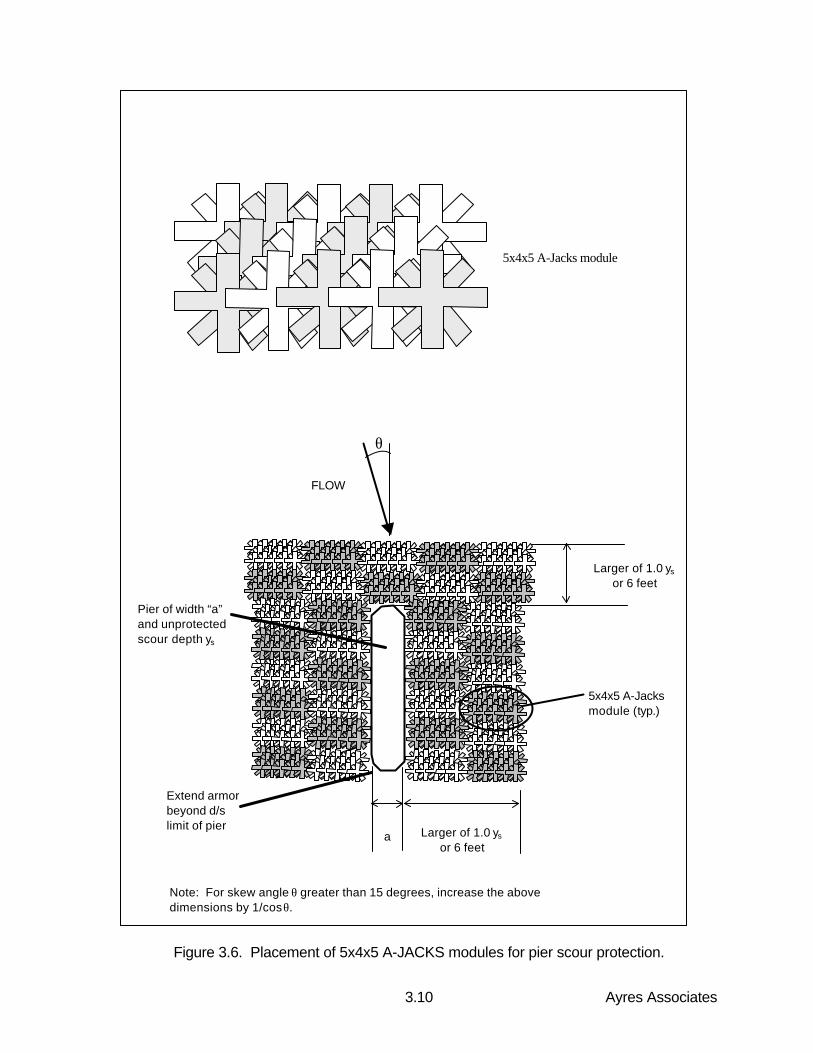
Ayres Associates3.10
Figure 3.6. Placement of 5x4x5 A-JACKS modules for pier scour protection.
a Larger of 1.0 ys
or 6 feet
Larger of 1.0 ys
or 6 feet
Pier of width “a”and unprotectedscour depth ys
Extend armorbeyond d/slimit of pier
FLOW
5x4x5 A-Jacksmodule (typ.)
Note: For skew angle θ greater than 15 degrees, increase the abovedimensions by 1/cosθ.
5x4x5 A-Jacks module
θ
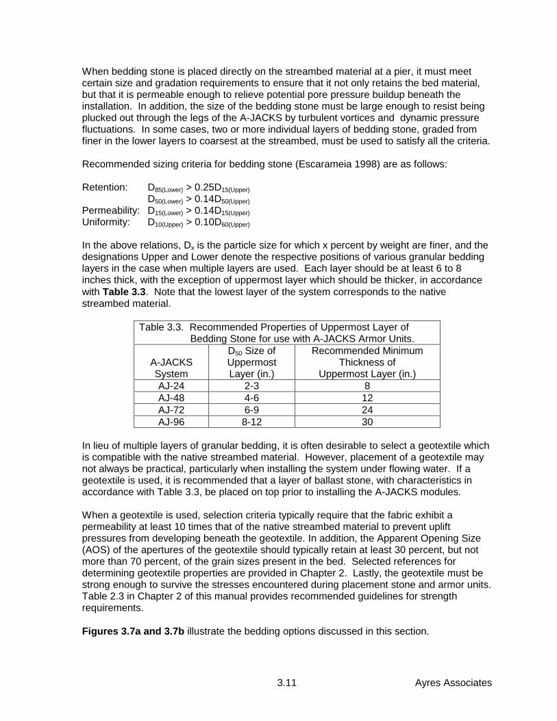
Ayres Associates3.11
When bedding stone is placed directly on the streambed material at a pier, it must meetcertain size and gradation requirements to ensure that it not only retains the bed material,but that it is permeable enough to relieve potential pore pressure buildup beneath theinstallation. In addition, the size of the bedding stone must be large enough to resist beingplucked out through the legs of the A-JACKS by turbulent vortices and dynamic pressurefluctuations. In some cases, two or more individual layers of bedding stone, graded fromfiner in the lower layers to coarsest at the streambed, must be used to satisfy all the criteria.
Recommended sizing criteria for bedding stone (Escarameia 1998) are as follows:
Retention: D85(Lower) > 0.25D15(Upper)D50(Lower) > 0.14D50(Upper)
Permeability: D15(Lower) > 0.14D15(Upper)Uniformity: D10(Upper) > 0.10D60(Upper)
In the above relations, Dx is the particle size for which x percent by weight are finer, and thedesignations Upper and Lower denote the respective positions of various granular beddinglayers in the case when multiple layers are used. Each layer should be at least 6 to 8inches thick, with the exception of uppermost layer which should be thicker, in accordancewith Table 3.3. Note that the lowest layer of the system corresponds to the nativestreambed material.
Table 3.3. Recommended Properties of Uppermost Layer of Bedding Stone for use with A-JACKS Armor Units.
A-JACKSSystem
D50 Size ofUppermostLayer (in.)
Recommended MinimumThickness of
Uppermost Layer (in.)AJ-24 2-3 8AJ-48 4-6 12AJ-72 6-9 24AJ-96 8-12 30
In lieu of multiple layers of granular bedding, it is often desirable to select a geotextile whichis compatible with the native streambed material. However, placement of a geotextile maynot always be practical, particularly when installing the system under flowing water. If ageotextile is used, it is recommended that a layer of ballast stone, with characteristics inaccordance with Table 3.3, be placed on top prior to installing the A-JACKS modules.
When a geotextile is used, selection criteria typically require that the fabric exhibit apermeability at least 10 times that of the native streambed material to prevent upliftpressures from developing beneath the geotextile. In addition, the Apparent Opening Size(AOS) of the apertures of the geotextile should typically retain at least 30 percent, but notmore than 70 percent, of the grain sizes present in the bed. Selected references fordetermining geotextile properties are provided in Chapter 2. Lastly, the geotextile must bestrong enough to survive the stresses encountered during placement stone and armor units.Table 2.3 in Chapter 2 of this manual provides recommended guidelines for strengthrequirements.
Figures 3.7a and 3.7b illustrate the bedding options discussed in this section.
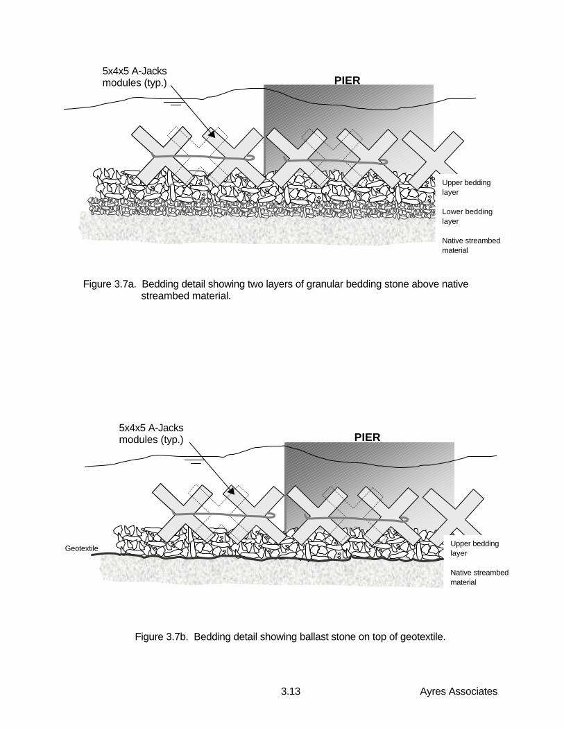
Ayres Associates3.13
Figure 3.7a. Bedding detail showing two layers of granular bedding stone above native streambed material.
Figure 3.7b. Bedding detail showing ballast stone on top of geotextile.
Upper beddinglayer
Lower beddinglayer
Native streambedmaterial
PIER5x4x5 A-Jacksmodules (typ.)
PIER
Upper beddinglayer
Native streambedmaterial
Geotextile
5x4x5 A-Jacksmodules (typ.)
Ayres Associates5.1
5. REFERENCES AND APPENDICES
American Association of State Highway Transportation Officials (AASHTO), 1995."Standard Specification for Geotextiles." AASHTO Designation M 288-96 DRAFT.February.
Bertoldi, D.A., et al., 1996. "An Experimental Study of Scour Protection Alternatives atBridge Piers." U.S. Federal Highway Administration Publication No. FHWA-RD-95-187.
Escarameia, M., 1998. "River and Channel Revetments: A Design Manual." ThomasTelford Publications, London.
Fotherby, L.M., and J.F. Ruff, 1995. "Bridge Scour Protection Using Toskanes, Phase 1."Pennsylvania Department of Transportation, Report 91-02, June.
Holmquist-Johnson, C.L., et al., 1999. "Laboratory Testing of A-JACKS Units for InlandApplications: Hydraulic Property Documentation." Colorado State University research reportfor Armortec Inc., February.
Industrial Fabrics Association, 1990. "A Design Primer: Geotextiles and Related Materials."St. Paul, Minnesota.
Lagasse, P.F., et al., 1995. "Stream Stability at Highway Structures." U.S. FederalHighway Administration Hydraulic Engineering Circular No. 20, Publication No. FHWA-IP-90-014, 2nd edition, November.
Lagasse, P.F., et al., 1997. "Bridge Scour and Stream Instability Countermeasures." U.S.Federal Highway Administration Hydraulic Engineering Circular No. 23, Publication No.FHWA-HI-97-030, July.
TC Mirafi, 1998. "Geotextile Filter Design Manual." Prepared by Geosyntec Consultants,Norcross, Georgia.
Neill, C.R., 1975. "Guide to Bridge Hydraulics." Roads and Transportation Association ofCanada, University of Toronto Press, 2nd edition.
Parker, et al., 1998. "Countermeasures to Protect Bridge Piers from Scour." University ofMinnesota draft final report No. NCHRP 24-7, prepared for the National CooperativeHighway Research Program, Transportation Research Board, May.
Parola, A.C., 1993. "Stability of Riprap at Bridge Piers." Journal of Hydraulic Engineering,ASCE, Vol. 119, No.10.
Quazi, M.E., and A.W. Peterson, 1973. "A Method for Bridge Pier Riprap Design." FirstCanadian Hydraulics Conference, Edmonton, Canada. Proceedings.
Richardson, E.V., and S.R. Davis, 1995. "Evaluating Scour at Bridges." U.S. FederalHighway Administration Hydraulic Engineering Circular No. 18, Publication No. FHWA-IP-90-017, 3rd edition, November.
Ayres Associates5.2
Thornton, C.I., et al., 1999. "Laboratory Testing of A-JACKS Units for Inland Applications:Pier Scour Protection Testing." Colorado State University research report for Armortec Inc.,February.
Thornton, C.I., et al., 1999. "Laboratory Testing of A-JACKS Units for Inland Applications:Full-Scale Testing." Colorado State University research report for Armortec Inc., February.
Vennard, J.K., and R.L. Street, 1975. "Elementary Fluid Mechanics." John Wiley & Sons,New York.