Embed Size (px)
Citation preview
Rsféréne»
*
DEPARTMENT OF THE ARMY FIELD MANUAL DEPARTMENT OF THE AIR FORCE MANUAL
FM 55-12 AFM 76-6
¿2 ¿5 f / 7
A
4
MOVEMENT OF ARMY UNITS IN
AIR FORCE AIRCRAFT
THE ARMY LIBRARY WASHINGTON, D. 0.
» DEPARTMENT OF THE ARMY AND THE AIR FORCE
30 APRIL 1974
\ 7)

1
#
t
4
#
FM 55—12/AFM 76-6
FIELD MANUAL • No. 55-12 AIR FORCE MANUAL '
No. 76-6
DEPARTMENTS OF THE ARMY
AND THE AIR FORCE
WASHINGTON, D.C., 30 April 1974
MOVEMENT OF ARMY UNITS IN AIR FORCE AIRCRAFT
CHAPTER 1.
2.
3.
4.
6.
6.
APPENDIX A.
B. C. D.
E. F. G. H.
I. J.
K. L.
M.
N. . O. P.
Q.
R.
S. T.
INTRODUCTION Purpose and Scope - Changes and Revisions Other Publications RESPONSIBILITIES General - - Responsibilities CONCEPT OF OPERATIONS General Control and Coordination I Participating Elements General Support Responsibilities PLANNING AND PREPARATION Mission Guidance Initial Planning Joint Planning Conference Preparation s. Final Coordination EXECUTION Departure Airfield Operations Arrival Airfield Operations SUPPORT FUNCTIONS Security Safety Communications Dangerous Materials REFERENCES GLOSSARY COMMUNICATIONS SAFETY CHECKLIST FOR VEHICLE
OPERATIONS UNIT MOVEMENT OFFICER LOAD PLANNING HAND AND LIGHT SIGNALS TRANSPORTED ARMY UNIT LIAISON
DETACHMENT VEHICLE INSPECTION CHECKLIST PREPARATION OF EQUIPMENT AND
SUPPLIES CENTER OF GRAVITY, CARGO, VEHICLE DOCUMENTATION DUTIES OF PLANELOAD COMMANDER ... DEPARTURE AIRFIELD OPERATIONS ARRIVAL AIRFIELD OPERATIONS MARSHALING CHECKLIST DEPARTURE AIRFIELD CONTROL GROUP
CHECKLIST ARRIVAL AIRFIELD CONTROL GROUP
CHECKLIST MARSHALING SECURITY
Paragraph Page
1- i i-i
1-2 1-1 1-8 1-1
2- 1 2-1 2-2 2-1
3-1 3-1 8-2 3-1 3- 3 3-1 8-4 3-2
4- 1 4-1 4-2 4-1 4-3 4-2 4-4 4-3 4-6 4-5
6-1 5-1 6-2 6-3
6-1 6-1 6-2 6-1 6-3 6-1 6-4 6-1
A-l B-l
C-l
D-l E-l F-l G-l
H-l 1-1
J-l K-l L-l M-l N-l 0-1
P-1
Q-l
R-l S-l T-l
j

FM 55—12/AFM 76-6
CHAPTER 1
INTRODUCTION
1-1. Purpose and Scope
a. This manual presents broad guidance for Army and Air Force organizations involved in unit movements of Army Forces on Air Force aircraft. It outlines the organization, functions, and responsibilities of Army Departure Airfield Control Groups/Arrival Airfield Control Groups (DACG/AACG) and their interface with Air Force Airlift Control Elements (ALCE) and Air Force Aerial Port Units. The Air Force has overall responsibility for operation of Air Force terminals; therefore, Joint Services Regulation AFR 76-7 (AR 59-106) takes precedence over this manual in connection with the handling and moving of traffic on Air Force organic or con- tracted aircraft or through air terminals of the Air Force.
b. This manual is applicable without modifica- tion to nuclear or nonnuclear warfare.
1-2. Changes and Revisions Users of this manual are encouraged to submit recommended changes or comments to improve its content. Comments should be keyed to the specific page, paragraph, and line of the manual in which the change is recommended. Rationale should be provided for each comment to insure understand- ing and complete evaluation. Comments from Army elements should be forwarded direct to Commandant, US Army Transportation School, ATTN: ATSTC-TDL, Fort Eustis, Virginia 23604. Comments from Air Force elements should be forwarded to Headquarters, US Air Force, ATTN: LGTX, Washington, D.C. 20330.
1—3. Other Publications Appendix A contains a complete list of current references to be used in conjunction with this manual.
1-1

!

FM 55-12/AFM 76-6
CHAPTER 2
RESPONSIBILITIES
2-1. General Conduct of a unit air movement requires plan- ning of loads, selection of equipment, processing of personnel, marshaling of transported units, airfield reception, outloading procedures, and the reception and disposition of forces at the off- load airfield. These tasks are the responsibility of the transported upit, its parent organization or station, the Army departure/arrival airfield con- trol group, the Air Force Airlift Control Element (ALCE), or when an ALCE is not assigned, the Air Force aerial port unit. Their degree of pro- ficiency in accomplishing these tasks and the degree of coordination between these units deter- mine the success of the movement.
2-2. Responsibilities a. Commanders of Continental US Armies.
The Commanding General of each Continental Army is responsible for providing departure/ arrival airfield control group(s) (DACG/AACG) as required for airlift operations within his geo- graphic area.
b. Commanders of Overseas Army Component Commands. The Commanding General of each overseas Army component command is responsible for providing DACG/AACG as required for air- lift operations supported or conducted within his command.
c. The Air Force is responsible for the air- lift operation at airfields where military forces are assembled for deployment by Air Force or- ganic and contracted aircraft. Control Element (ALCE) will be assigned to support the airlift operation. When an ALCE is not assigned, an Air Force aerial port unit will be assigned and be responsible for the airlift operation; there- fore, when the term “ALCE,” is used herein it applies equally to an aerial port unit in such a situation.
d. Detailed responsibilities of participating organizations and agencies are outlined for each functional area discussed in the text and appen- dixes.
2-1

FM 55-12/AFM 76-6
CHAPTER 3
CONCEPT OF OPERATIONS
3-1. General a. An air movement operation involves the air
transport of units, personnel, supplies and equip- ment, including airdrops/extractions and air landings, and covers both tactical and administra- tive movements. A movement by other modes of transportation may precede or follow air move- ment.
b. The conduct of an airland operation requires that participating forces be properly integrated to achieve a common objective. Air movement operations may be conducted by any of the joint force organizations: a unified command, a subordinate unified command, or a joint task force. Planning for the operation must include provision of forces to support the staging and out- loading of the airlifted force. Continuous co- ordination between the transported unit(s), the transporting unit(s), and other supporting act- ivities is necessary.
c. The conduct of an airland operation consists of two primary phases, the planning and prepara- tion phase and the execution phase. Each of these two phases is, in turn, divided into major func- tional areas. The five functional areas of the plan- ning and preparation phase are:
(1) Mission guidance (2) Initial planning (3) Joint planning (4) Unit preparation (5) Final coordination
d. The two functional areas of the execution phase are:
(1) Departure airfield operations (2) Arrival airfield operations
3-2. Control and Coordination
Air movement operations require close control of all participating units and close coordination of the many interservice activities. The Air Force Component/Mission Commander will exercise
overall control of the airlift operation at the departure and arrival airfields. Airlift resources will, at all times, remain under the operational control of the Air Force Component/Mission Commander. The resources of the deploying unit are under the control of the unit commander until passed to the Departure Airfield Control Group (DACG) at the alert holding area and, in turn, passed to the Air Force Component/Mission Com- mander at the loading ramp area. Control of the resources revert to the unit commander upon release by the Arrival Airfield Control Group (AACG) at the arrival airfield. To provide neces- sary control and coordination and to provide a jointly manned facility for exchange of pertinent information relating to the progress of the opera- tion, an Airlift Operations Center (AOC)/Aerial Port Operations Center (APOC) is established by the Air Force at both departure and arrival airfield. All information affecting the load’ng/ offloading operations will be funneled through the APOC. Each of the pr'nc’pal representatives in the AOC/APOC will have continuous com- munications with the activities of their organiza- tions as outlined in paragraph 6-3 and appendix C.
3-3. Participating Elements
a. Departure/Arrival Airfield Contro- Groups (DACG/AACG).
(1) A DACG/AACG normally is organized . as a provisional unit from personnel resources I which are not required to accompany the trans- “ ported force. It should be manned for one, two.
or three shift operation, as indicated by the mis- sion.
(2) Personnel to establish and operate the I control groups may be drawn from ava'lable re- I sources to form provisional units.
(3) The DACG/AACG organization must be structured to provide essential support for the transported force. As a minimum, the DACG/ AACG consists of a command and an operations element, and other administrative and support-
3-1
FM 55-12/AFM 76-6
ing personnel as determined by the size and scope of the operation. The DACG/AACG is the Army point of contact with the Air Force ALCE at the departure/arrival airfield(s). The DACG/ AACG organization should be designed and trained in advance of the operation, so that it is fully capable of rapid assembly for movement by air to selected areas in advance of the elements it will support. Where practical, a survey of the marshaling/outload area should be accomplished by the DACG/AACG to provide current and ac- curate information on facilities available and sup- port considerations required.
i (4),Jt is essential that all personnel re- ponsible for supervision of the outloading are thoroughly familiar with the loading procedures, applicable to the types of aircraft to be loaded, and it is desirable that they be experienced in air movement operations.
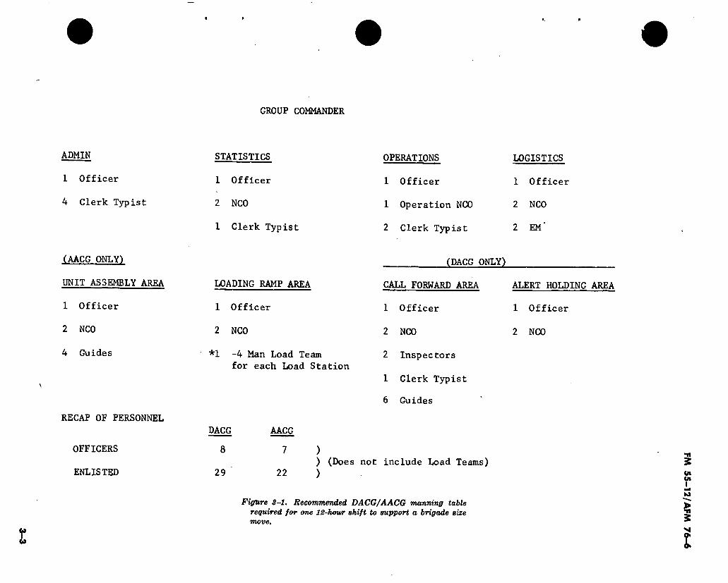
(5) Figure 3-1 is a recommended manning table for one 12-hour shift of DACG/AACG sup- porting a brigade size move. Based on similar manning, spaces are suggested for DACG and AACG since either should be cápable of perform- ing departure and arrival control functions.
(6) The DACG/AACG should undergo train- ing in its duties and responsibilities as outlined in FM 57-1. Periodic rehearsals are particularly helpful for provisional units where personnel turnover is a significant factor in training and operational proficiency. Assignment of special units to support air movement plans will allow the issue of mission letters to participating units. The value of advance information to each unit concerning its tasks and responsibilities cannot be overemphasized. This not only allows the selected units to plan in advance, but enables them to cross-train between units. The commander of the group will then be able to organize and train for his assigned mission.
b. Airlift Control Element (ALCE).
(1) The ALCE is an element of the Air Force command and control system. An ALCE is employed when required at departure, en route, and arrival airfields used by the airlift units. The mission of the ALCE is to plan airlift control operations for a given base ; to survey the facilities of that base ; and to control, coordinate, and report airlift operations at that base.
(2) The ALCE maintains operational con- trol over airlift units and all airlift aircraft participating in an operation while on the ground at the ALCE site, and coordinates all Aii Force
operational aspects of the mission. The ALCE is responsible for aircraft movement control, com- munications, technical supervision of onloading and offloading operations, aeromedical evacua- tion, marshaling of aircraft, and continuous liaison with all interested agencies to insure that the operation is proceeding according to plan.
(3) Collocated with or assigned as a com- ponent unit of the ALCE is the aerial port unit. Within the aerial port unit is the Aerial Port Operations Center (APOC). The APOC performs as the air transportation coordinating activity for the ALCE. Matters pertaining to air trans- portation of passengers and cargo are normally referred to the APOC. Units requiring technical assistance in planning unit moves will follow procedures in paragraph 4-2a(5).
(4) The ALCE procedures contained in this manual are to familiarize the deploying unit and DACG/AACG with the functions and assistance normally provided by an ALCE. These procedures are limited primarily to the aerial port functions of an ALCE that impact on mission planning, preparation, and execution of airlift operations.
3-4. General Support Responsibilities
a. The following support may be required by the ALCE from the Army or Air Force depart ture/arrival airfield commander:
(1) Officespace
(2) Work centers
(3) Communications
(4) Aircraft parking area
(5) Billets (6) Cargo marshaling area
(7) Vehicles and vehicle maintenance (wrecker service)
(8) Food service
(9) Medical
(10) Flying and ground safety
(11) Security (12) Air terminal facility (passenger)
(13) Cargo breakdown/buildup storage area
ft. The parent station is responsible for the planning and executing the physical movement of its units and for insuring that each brigade, battalion, or separate company establishes a unit movement center in the marshaling area and provide liaison to the DACG well in advance of
3-2
GROUP COMMANDER
ADMIN
1 Officer
4 Clerk Typist
STATISTICS
1 Officer
2 NCO
1 Clerk Typist
OPERATIONS
1 Officer
1 Operation NCO
2 Clerk Typist
LOGISTICS
1 Officer
2 NCO
2 EM'
\
(AACG ONLY)
UNIT ASSEMBLY AREA
1 Officer
2 NCO
4 Guides
(DACG ONLY)
RECAP OF PERSONNEL
OFFICERS
ENLISTED
LOADING RAMP AREA
1 Officer
2 NCO
*1 -4 Man Load Team for each Load Station
DACG
8
29
AACG
7
22
CALL FORWARD AREA
1 Officer
2 NCO
2 Inspectors
1 Clerk Typist
6 Guides
) ) (Does not include Load Teams)
)
ALERT HOLDING AREA
1 Officer
2 NCO
Figure 3-1. Recommended DACG/AACG manning table required for one 12-hour shift to support a brigade size move.
I
FM
55-1
2/A
FM 7
6-6
FM 55-12/AFM 76-6
the arrival of the unit. The parent station will provide liaison personnel for units smaller than company size. Plans should also provide for simi- lar liaison to the AACG.
c. The parent station staff provides the fol- lowing staff services as required to support the air movement operation:
(1) S-l. (a) Provides personnel for administrative
preparation for the movement. (&) Provides personnel for the liaison
detachments. (c) Assists transported unit S-4 in the
preparation of manifests. (d) Provides personnel services during
marshaling and movement planning. (2) S-2. Provides normal S-2 support and
will be prepared to assist where needed during the marshaling and movement phase.
(3) S-3. (a) Coordinates air movement training. (b) Establishes communication in accord-
ance with S-4 marshaling plan. (c) Prepares plans and orders for tactical
airlift operations. (4) S-4. The S-4 has staff proponency for
air movement of the unit. Normally the staff transportation officer, acting for the S-4:
(a) Develops airlift requirements.
(b) Prepares and disseminates necessary plans and orders for administrative airlift opera- tions.
(c) Supervises preparation of unit load- ing plans and airloading tables.
(d) Designates aircraft chalks for sub- ordinate units.
(e) Publishes an extract of the air move- ment table applicable to units of the station.
(/) Exercises staff responsibility for unit marshaling plans and activities.
(g) Establishes a movement team at the marshaling area.
(h) Publishes the marshaling plan. (i) Establishes requirement for, requests
and coordinates, logistical support. (j) Supervises preparation of equipment
and supplies for air movement. (k) Establishes and supports unit mar-
shaling areas. (l) Prepares movement schedules for
movement from marshaling area to the alert hold- ing area as coordinated with DACG.
(m) Provides technical supervision in pre- paration of manifests.
(TO) Procures and supervises augmenting transportation when required.
(q) Establishes liaison for continuous co- ordination with the DACG.
(p) Procures and provides required shor- ing.
3-4
FM 55-12/AFM 76-6
CHAPTER 4
PLANNING AND PREPARATION
4-1. Mission Guidance
The deploying unit commander and all support- ing forces require the following information to prepare for an airlift operation.
a. Mission.
b. Force strength1 and composition.
c. Location of departure airfield/arrival air- field.
d. Departure date.
e. Closing time.
f. Liaison, including the names, location, and telephone number of the deploying unit com- mander (s) and commanders of DACG, AACG, ALCE, aerial port unit, and other supporting activities.
g. Mutually agreed time and location of the Joint Planning Conference.
4-2. Initial Planning
Actions necessary to prepare the deploying unit and support elements to participate in the joint planning conference include:
a. Deploying Unit. The unit will : (1) Identify the number of personnel and
type/quantity of cargo and equipment to be moved. (2) Establish priorities for arrival. (3) Establish liaison with the supporting
ALCE, DACG, AACG and others. (4) Identify cargo/equipment that is sensi-
tive, dangerous, outsized or requires special handling, réference TM 38-250/AFM 71-4.
(5) Request technical assistance for pre- paring equipment and training personnel. This assistance can normally be obtained from the supporting ALCE. Technical assistance can be obtained in CONUS from the affiliated Military Airlift Command (MAC) ALCEs are located at McGuire AFB, NJ ; Dover AFB, WA ; Hickam AFB, HI; and Rhein Main AB, Germany. Within
TAC, HQ 1st Port Group is located at Langley AFB, VA, with subordinate aerial port squadrons located at Dyess AFB, TX; Little Rock AFB, AR; and Pope AFB, NC; and Langley AFB, VA. In oversea commands, assistance can be obtained from aerial port units at practically any major airfield. This technical assistance generally in- cludes:
(a) Instructions in preparation of cargo/ equipment for movement.
(ft) Instructions for documentation and manifesting.
(c) Instructions for loading and offloading aircraft including restraint procedures.
(d) Aircraft load planning assistance. (6) Plan and coordinate staff assistance in
the areas of administrative support, unit air movement training, air movement planning, logistics and maintenance support. Training of the deploying unit should include indoctrination in the standard safety practices of operation in and around aircraft (app D).
(7) Appoint a unit movement officer (UMO). (8) Insure the unit movement officer (UMO)
folder is current and covers all items contained in appendix E.
(9) Develop traffic plan for movement to vicinity of the departure airfield.
b. Departure Airfield Control Group. The DACG will:
(1) Determine from the troop list the size and type unit(s) to be outloaded.
(2) Determine the time frame during which outloading will be accomplished.
(3) Determine location of departure air- field (s) and marshaling area(s).
(4) Determine departure airfield’s logistical/ administrative facilities available to DACG and outloading unit.
(5) Develop a tentative organizational structure and staffing including special person- nel skills, administrative requirements, and com-
4-1
FM 55-12/AFM 76-6
munications prior to the joint planning confer- ence.
(6) Establish liaison with deploying unit, and other supporting activities.
(7) Coordinate with the ALCE to establish DACG training requirements.
c. Arrival Airfield Control Group. The AACG will:
(1) Determine from the troop list, the size and type unit(s) to be received.
(2) Determine the time frame during which offloading will be accomplished.
(3) Determine location of arrival airfield(s) and release/holding areas.
(4) Determine logistical and administrative facilities available to AACG and deployed unit at the arrival airfield.
(5) Develop a tentative organizational structure and staffing including special personnel skills, administrative requirements, and com- munications prior to the joint planning confer- ence.
(6) Establish liaison with supported unit, the ALCE and other supporting activities.
(7) Coordinate with the ALCE to establish AACG training requirements.
d. Air Force, Component. The representative(s) from the Air Force Major Command(s) providing the airlift resources will:
(1) Review the mission directive and scope of operation for the purpose of preparing a ten- tative flow schedule and plan of operation.
(2) Provide appropriately qualified person- nel for the airfield survey team.
(3) Establish initial coordination with the deploying unit through the DACG/AACG to re- view:
(a) Personnel, cargo, and equipment to be moved.
(&) Deploying unit movement priorities and any impact on established ground times.
(c) Dangerous or outsized equipment/ cargo that may require special handling proce- dures and inspections.
(d) Requirements for assistance. (e) US/Foreign customes requirements
and procedures.
4—3. Joint Planning Conference Due to the need for close coordination and to in-
sure a clear understanding of responsibilities, a series of joint conferences are required during the planning phase. As a minimum these joint conferences will include a joint planning con- ference held as soon as possible after receipt of the air movement mission and a final coordina- tion conference held immediately prior to the in- itiation of the move. All participating elements should be represented at these conferences by key personnel empowered to resolve problems and make decisions for their organization. These for- mal conferences do not negate the need for con- tinuous coordination throughout the planning cycle.
a. Deploying Unit. The unit will: (1) Provide a consolidated listing of move-
ment priorities by subordinate units (troop list).
(2) Provide a list of weight and dimensions of materiel to be moved for each unit.
(3) Identify equipment with unusual de- sign or modifications and dangerous or pallet1 zed cargo that may require waivers, special handling/ loading procedures (app L and TM 38-250/ AFM71-4).
(4) Determine requirements for. type and source of materials to be used to restrain cargo in vehicles/trailers.
(5) Determine inspection procedures and documentation requirements for dangerous car- go and organizational equipment (app L and TM 38-250/AFM 71-4).
(6) Coordinate the number of aircraft load teams required.
(7) Coordinate procedures for transport- ing individual weapons/ammunition/equipment.
(8) Determine shoring requirements.
b. Departure Airfield Control Group. The DACG will:
(1) Determine any special requirements for personnel and equipment including a weighing capability.
(2) Confirm unit deployment schedule.
(3) Coordinate with the Air Force on the type and number of aircraft to be utilized.
(4) Confirm strength of outloading unit. (5) Consolidate unit shoring requirements. (6) Coordinate the use of departure air-
field facilities. (7) Confirm coordination contacts.
4-2

FM 55-12/AFM 76-«
(8) Obtain list of unit materiel to be out- loaded (including weight and dimensions of each item).
(9) Finalize DACG organization and train- ing requirements.
c. Arrival Airfield Control Group. The AACG will:
(1) Determine special AACG requirements for personnel and equipment.
(2) Confirm arrival schedule. (3) Coordinate type and number of aircraft
utilized. (4) Confirm strength of deploying unit. (5) Confirm coordination contacts. (6) Coordinate the use of arrival airfield
facilities/release and holding areas. (7) Obtain list of unit materiel to be off-
loaded. (8) Finalize AACG organization and train-
ing requirements.
d. Air Force Component. The representative ( s') from the Air Force Major Command(s) pro- viding the airlift resources will:
(1) Confirm type and number of aircraft allocated to move personnel, cargo and equ:pment.
(2) Establish requirements for customs clearance procedures, any special handling pro- cedures and inspections deemed necessary for dangerous, outsized or unusual equipment/cargo.
(3) Coordinate movement priorities estab- lished by deploying unit.
(4) Coordinate the requirement for special training or load planning assistance to be pro- vided the deploying unit.
(5) Coordinate dates, times, and place train- ing will be conducted.
(6) Determine the requirement for mater- ials handling equipment, weighing equipment, 463L pallets, cargo nets, etc.
(7) Confirm coordination contacts. (8) Provide a briefing on the tentative
plan of operations, including a flow schedule, vehicle and personnel traffic plan, aircraft park- ing, communications plan and safety require- ments.
(9) Identify other operational problems.
4—4. Preparation Preparation for air movement begins with receipt of the mission directive/order, and continues
through the planning phase until execution begins.
a. Deploying Unit. The unit will: (1) Jointly prepare the air movement plan
with the Air Force planning representative. The air movement plan includes the composition of aircraft, loads, organization of serials, and in- structions for flight of the aircraft from the loading area to the arrival area.
(2) Jointly prepare the air movement table with the Air Force planning representative. The air movement table provides detailed instructions on flight/serial composition, the number of air- craft allocated, time for loading and takeoff, loading sites and landing areas, and prescribes the timing of the operation (app F).
(3) Prepare an aircraft loading table, based on the air movement table, which is jointly pre- pared by the commanders of the transported and transportating units (appF).
(4) Organize and train unit loading teams in basic principles and procedures for loading/ offloading and restraining equipment/supplies in Air Force aircraft. Air Force technical as'ist- ance required for training should be ertab^shcd during the joint planning conference.
(5) Train unit vehicle drivers a ’d rqui]v ment operators in conditions simulating aircraft, loading and offloading, including forward and re- verse operations on inclined plane.
(6) Instruct vehicle operators and gu des n standard hand signals for positioning whee’ed/ tracked vehicles as contained in appendix G.
(7) Assign duties and responsibilities to unit liaison personnel as determined dur:ng the joint planning conference (app H).
(8) Finalize movement priorities for plane- loads of unit personnel and materiel.
(9) Prepare vehicles/equipment and supplies for air movement. See the Vehicle Inspection Checklist in appendix I for the minimum inspec- tion requirement for air movement.
(10) Prepare dangerous cargo and cargo re- quiring special handling for air movement in ac- cordance with TM 38-250/AFM 71-4 and as specified in the joint planning conference. Re- quirements include:
(a) Ammunition ready racks located on various tracked vehicles will not be utilized dur- ing air movement. Ah ammunition will be pro- perly restrained in approved ammunition con-
4-3
FM 55-12/AFM 76-6
tainers, trailers, or trucks, or will be palletized. Restraints will be in accordance with chapter 4, TM 55-450-15. (Waivers to these conditions will be processed in accordance with the provi- sions of TM 38-250/AFM 71-4).
(5) Ammunition will not be carried in the chamber of any weapon nor carried in clips or magazines inserted in weapons aboard Air Force aircraft. Ammunition not carried as cargo will be under close supervision of the planeload commander and not in the hands of individual troops.
(c) Personnel assigned to guard security equipment, who require loaded weapons, should be identified and their presence should be made known to the aircraft commander.
(d) Fuel tankers/refuelers will be drained and purged (TM 38-250/AFM 71-4).
(11) Prepare to stow individual weapons/am- munition as established during the joint planning conference. Normally weapons/ammunition will be boxed or crated for movement. If operational requirements dictate, weapons/ammunition may be transported by one of the following methods.
(a) Secured on the unit vehicle equip- ment.
(6) Secured to individual duffle bags. (c) Retained by the individual. (For ex-
tended flights this method is the least desirable due to the limited space around troop seats for stowing weapons.)
(12) Prepare to stow individual web equip- ment and helmets as established at the joint planning conference.
(13) Prepare vehicles and equipment for air movement by rendering them completely service- able and insuring that all lifting/tiedown shackles and devices are in position and serv- icable. Additional preparation instructions are contained in appendix J.
(14) Stow and secure unit equipment and supplies on vehicles and trailers to the maximum extent consistent with the rated cross-country load of the vehicle and instructions contained in appendix J.
(15) Determine the gross weight of each ve- hicle, outsize item of equipment, each loaded pal- let and container. In the event adequate scales are not available to the unit commander for weighing equipment, the method for determining weights will be resolved in the joint planning conference. Weights will be marked with a weath- er resistant material and in an easily distinguish- able location on the item.
(16) Determine and mark conspicuously on the item the center of gravity (CG) of each vehicle, equipment item, and container of supplies. In addition when trucks and trailers are to be transported coupled, determine and mark the combined CG.
Note. Do not compute or record the CG of any container . less than 100 inches in length. Methods of determining CG are contained in appendix K.
(17) In coordination with the supporting Air Force activity, develop specific aircraft loads. Specific aircraft loads are entered on the air- craft loading tables. Additional guidance on load planning is contained in appendix F.
(18) Prepare personnel and cargo manifests in accordance with appendix L or as specified in the joint planning conference.
(19) Provide key personnel participating in the operation with distinctive identification, such as arm bands, hat bands or badges to assist in coordination. These markings will be coordin- ated with supporting personnel and as a mini- mum, will be provided the following unit repre- sentatives:
(a) Unit load team supervisor. (&) Unit liaison officers/NCO’s. (c) Planeload commander.
Personnel will be briefed on distinctive identifi- cation afforded key supporting personnel ; ALCE, DACG and Senior Loadmaster.
(20) Designate a planeload commander for each aircraft. Duties of the planeload commander are stated in appendix M. In addition an assist- ant planeload commander will be designated when:
(a) The load consists of equipment with drivers/operators plus additional personnel.
(b) The plane load is assembled in more than one area for final preparations, inspections and briefings.
(21) Obtain required shoring.
b. Departure Airfield Control Group. The DA- CG will:
(1) Assemble DACG personnel and assign duties.
(2) Insure that the unit obtains shoring materiel as required.
(3) Establish departure airfield operational areas in coordination with ALCE.
(4) Perform training necessary to insure that all DACG personnel are qualified to perform mission.
FM 55-12/AFM 76-6
(5) Collocate with supporting Aerial Port Operations Center (APOC) and maintain close liaison with supported unit.
(6) Establish requirements for communica- tions (para 6-3 and app C).
(7) Provide key personnel participating in the operation with distinctive markings to assist in coordination. These markings will be coordin- ated with other participants.
(8) Prepare briefing charts depicting the airfield area and brief all key personnel on the sequence of events planned for the execution phase.
c. Arrived Airfield Control Group. The AACG will:
(1) Assemble AACG personnel and assign duties.
(2) Collocate with the supporting APOC, maintain close liaison with the supported unit and insure rapid clearance of the ramp area.
(3) Establish arrival airfield operational areas in coordination with the ALCE.
(4) Perform training necessary to insure that all AACG personnel are qualified to per- form mission.
(5) Establish procedures for the recovery of shoring and 463L pallets.
(6) Establish requirements for communica- tions (para 6-3 and app C).
(7) Provide key personnel participating in the operation with distinctive markings to assist in coordination. These markings will be coor- dinated with other participants.
(8) Provide briefing charts depicting the airfield area and brief all key personnel on the
sequence of events planned for the execution phase.
d. Air Force Component. The representa- tive(s) from the Air Force Major Command(s) providing the airlift resources will:
(1) Insure the establishment of an ALCE at departure, en route, and arrival airfields.
(2) Establish an APOC and provide ade- quate space for working parties of the DACG/ AACG.
(3) In coordination with the deploying Army unit, jointly develop detailed load plans.
(4) Insure communications network is es- tablished (para 6-3 and app C).
(5) Arrange to maintain statistical record of arrivals, departures, loading time, tonnage, and other pertinent data in accordance with MAC/TAC Airlift Control Element Manual 55- 25 and TAC Aerial Port Operations, TAC Man- ual 55-48.
(6) Insure that an ALCE member is pre- pared to conduct a final briefing for the deploy- ing unit and all supporting elements and to es- tablish or confirm responsibilities, procedures, schedules, vehicle and personnel traffic routes, and safety requirements.
4-5. Final Coordination The task force commander or his representative should conduct a final joint coordination meet- ing with representatives of the deploying unit. DACG/AACG and ALCE. At the final co--rd'na- tion meeting, the deploying unit, DACG/AACG and ALCE present the status of their planning to identify any problems.
4-5

FM 55-12/AFM 76-6
CHAPTER 5
EXECUTION
5-1. Departure Airfield Operations Departure airfield operations (app N) are out- lined in four separate areas of activity and de- lineates the responsibilities of the deploying unit, DACG and ALCE within each area. The four areas are the marshaling area, alert holding area, call forward area and loading ramp area. The ALCE coordinates the overall airlift operations at the departure airfield.
a. Marshaling Area Activities. Marshaling area activities are the responsibility of the deploying unit commander. The marshaling activities may take place within the deploying units’ perman- ent area or in another area when this will facili- tate movement and control. In either case the marshaling area activities should take place as close as possible to the departure airfield with- out causing unnecessary congestion to the airfield operations or undue hardship to the deploying unit.
(1) Deploying Unit. The parent station is responsible for the movement of its subordinate units. The deploying unit will:
(a) Establish liaison with the DACG and, with other activities as agreed during the joint planning conference. *
(b) Perform final preparations of ve- hicles and equ;pment in accordance with appen- dixes I, J, and K.
(c) Insure that adequate shoring mater- ial is on hand.
(d) Prepare personnel and cargo mani- fests in accordance with appendix L.
(e) Pass control of unit aircraft loads/ chalks to the DACG at the alert holding area.
(/) Assemble personnel, supplies and equipment into aircraft loads consistent with es- tablished load plan.
(g) Insure planeload commanders are properly briefed on their responsibilities as out- lined in appendix M.
(2) Departure Airfield Control Group. The DACG will:
(a) Maintain liaison with the deploying unit.
(&) Arrange with ALCE for Air Force technical assistance required by the deploying unit.
(c) Establish communications (para 6-3 and app C).
(<Z) Call aircraft loads/chalks forward from the marshaling area and assume control in the alert holding area.
(3) Airlift Control Element (Aerial Port Function). The aerial port unit will:
(a) Provide technical assistance to the I deploying unit in the preparation of vehicles and i equipment for loading.
(5) Initiate movement of units aircraft loads/chalks through the various control points of the outloading process by providing call for- ward times to the DACG.
b. Alert Holding Area Activities. The alert holding area is a vehicle and passenger traffic control area in the vicinity of the departure air- field used to assemble, hold, and service aircraft loads/chalks. Control of the load/chalk is trans- ferred to the DACG at this point.
(1) Deploying Unit. The deploying unit will:
(a) Insure that the aircraft load/chalk ar- rives at the alert holding area at the time speci- fied by the DACG.
(b) Provide the DACG with cargo and personnel manifests.
(c) Correct discrepancies detected during the DACG inspection.
(2) Departure Airfield Control Group. The / DACG will:
(a) Receive and control aircraft loads/ chalks as they arrive in the alert holding area.
* (b) Establish a discrepancy correction/ maintenance and service area.
' (c) Inspect aircraft loads/chalks to in- sure that they are complete and properly pre- pared. Inspectors will use the vehicle checklist in appendix I.
5-1

FM 55-12/AFM 76-«
(d) Inspect documentation for accuracy and completeness.
(e) Direct or guide the aircraft load/ chalk to check point 1 (joint inspection area) when requested by the aerial port representa- tive.
(3) Airlift Control Element (Aerial Port Function). The aerial port unit will:
(a) Assist the DACG where required. (b) Call the aircraft load/chalk to check
point 1 (joint inspection area) through the DA- CG.
c. Call Forward Area Activities. The call for- ward area is that portion of the departure air- field where the joint inspection is conducted (check point 1) ; a final briefing is provided to the deploying troops and manifests are reviewed for accuracy (check point 2).
(1) Departure Airfield Control Group. The DACG will:
(a) Establish communications (para 6- 3 and app C).
(b) Assist in the conduct of the joint in- spection of aircraft loads/chalks and manifests.
(c) Insure that cargo and personnel mani- fests are correct prior to releasing to the aerial port.
{d) In the event of aircraft aborts or dis- crepancies in the planned ACL, reassemble air- craft loads/chalks with the assistance of the aer- ial port and prepare required manifest changes.
(e) Insure that drivers/operators correct minor discrepancies detected during the joint in- spection.
(/) Maintain statistical data to account for the current status of all unit personnel and materiel scheduled for air movement.
(flr) Insure the deploying unit adheres to the established timetable.
(h) Escort aircraft loads/chalks to the loading ramp area ready line.
(i) Retain a final corrected copy of each manifest.
O') Insure that deficiencies noted during the joint inspection are relayed to the alert holding area and the unit to prevent recurring deficiencies.
(k) Provide fueling and defueling capa- bility for vehicles to be transported. *
(2) Airlift Control Element (Aerial Port Function). The aerial port unit will:
(a) Coordinate with the DACG on any changes that may be required to the aircraft load/chalk configuration due to unknown changes
such as substitutes in aircraft type, variations in aircraft cargo compartment or changes in the planned ACL.
(b) Together with the DACG inspec- tor, conduct the joint inspection of equipment (app I and J).
(c) Brief drivers and passengers on flight line safety including driving procedures, smok- ing rules, precautions and special topics as re- quired (app D).
(d) Notify the DACG when loads are to be dispatched to the loading ramp area ready line.
d. Loading Ramp Area Activities. The load- ing ramp ai’ea is controlled by the aerial port unit. Aircraft loads/chalks are guided to an es- tablished ready line. At the ready line, the air- craft load/chalk is placed under the control of the aircraft primary loadmaster/aerial port load team for aircraft loading.
(1) Deploying Unit. The planeload com- mander will:
(a) Report to the aerial port unit loading ramp area representative.
(b) Maintain control of his load/chalk. (c) Retain one copy of the cargo and
passenger manifests. (d) As directed by the DACG, assist in
loading and securing the aircraft load/chalk. Note. Vehicle drivers/equipment operators will follow
the instructions of the individual designated by the pri- mary loadmaster while loading equipment on the aircraft.
(2) Departure Airfield Control Group. The DACG will:
(a) Insure that the deploying unit has necessary shoring.
(b) Maintain coordination with the de- ploying unit representative and APOC.
(c) Insure Army load teams are avail- ji able and briefed to perform their duties. Insure i the Army loading team supervisor has the dis- ! tinctive marking agreed upon during the joint
planning conference. (3) Airlift Control Element (Aerial Port
Function). The aerial port unit will: (a) Accept plane loads from the DACG
at the loading ramp area (ready line). (b) Insure that all drivers have been
briefed on flightline safety to include driv'ng procedures, smokmg rules, precaut'ons, and spe- cial topics as required.
(c) Insure that each aircraft load/chalk is guided to the proper ready line at the specified time.
5-2
FM 55-12/AFM 76-«
(d) Maintain liaison with the aircraft pri- mary loadmaster and the DACG.
(e) Deliver the load/chalk to the aircraft primary loadmaster at the ready line and assist the primary loadmaster in loading.
(/) Provide and operate materials hand- ling equipment, special loading equipment and materials in accordance with AR 59-106/AFR
I 76-7 and agreements established during the joint planning conference.
(g) Maintain communications in accord- ance with paragraph 6-3 and figure C-l.
(h) Provide the primary loadmaster with the required copies of the personnel and cargo manifests and retain a copy for aerial port files.
(4) Aircraft Primary loadmaster. The primary loadmaster will: J
(a) Receive the load/chalk at the ready line.
(b) With representatives of ALCE, DA- CG or unit, conduct joint inspection of Army equipment load.
(c) Direct and supervise the Army load- ing teams and aircraft load/chalk vehicle driv- ers.
(d) Direct all loading operation and in- sure that all equipment and supplies are pro- perly restrained in the aircraft.
(e) Coordinate with the aerial port load- ing ramp area representative for any special assistance or equipment needed.
(/) Collect required copies of the cargo and personnel manifest from the aerial port rep- resentative.
(g) Conduct preflight briefing to all ac- companying troops.
5—2. Arrival Airfield Operations Appendix 0 outlines two separate areas of ac- tivity and delineates the responsibilities of the deploying unit, the AACG and the ALCE within each area. The two areas are the offloading ramp area and the holding area. Arrival airfield opera- tions insure that arriving aircraft are offloaded in a timely manner and that the equipment, sup- plies and personnel of each planeload proceed immediately to the holding area.
a. Offloading Ramp Area Activities. The off- loading ramp area activities are controlled by the aerial port. Aircraft loads/chalks are off- loaded from the aircraft and released to the AA- CG for return to unit control.
(1) Deploying Unit. The planeload com- mander will:
(a) Assist the primary loadmaster as di- rected.
(b) Receive instructions from the aerial port ramp coordinator.
(c) Insure that all aircraft tiedown equip- ment, pallets, nets, etc., are left at the aircraft or returned to the aerial port unit.
(d) Turn in shoring to the AACG. (e) Provide one copy of personnel and
cargo manifest to the AACG. Note. Vehicle drivers/equipment operators will follow
the instructions of the individual designated by the pri- mary loadmaster while offloading from the aircraft.
(2) Arrival Airfield Control Group. The AACG will:
(a) Maintain coordination with the de- ploying unit and the aerial port representative.
(b) Insure Army load teams are avail- able and briefed to perform their duties. Insure the offload team chief has the distinctive mark- ing agreed upon during the joint planning con- ference.
(c) Coordinate with the aerial port off- loading ramp coordinator for the recovery and storage of shoring material.
(d) Obtain a copy of each cargo and per- sonnel manifest from the aerial port represen- tative.
(e) Accept each planeload from the aer- ial port unit at the established release point.
(3) Airlift Control Element (Aerial Port Function). The aerial port unit will:
(a) Receive two copies of the load/chalk cargo and personnel manifest from the aircraft primary loadmaster.
(b) Coordinate the removal of all equip- ment, supplies and personnel from the aircraft and ramp offloading area.
(c) Provide and operate materials hand- j ling equipment, special offloading equipment,
¡ and materiels in accordance with AR 59-106/ AFR 76-7 and agreements established during the joint planning conference.
(d) Provide communications in accord- ance with paragraph 6-3 and figure C-l.
(e) Inform the AACG of any change in operations.
(/) Maintain statistical data on the op- eration.
(g) Release the load/chalk to the AACG at the established release point.
b. Holding Area Activities.
5-3
FM 55-12/AFM 76-6
(1) Deploying Unit. The deploying unit will:
(а) Provide unit liaison personnel to the AACG as determined in the joint planning con- ference.
(б) Assist the AACG as required. (2) Arrival Airfield Control Group. The
AACG will: (a) Maintain coordination with the AL-
CE, the deploying unit, and the APOC. (b) Provide facilities as determined dur-
ing the joint planning conference.
(c) Maintain records on personnel and equipment received and cleared.
(d) Release aircraft load/chalk to the de- ploying unit commander or his representative at a predesignated location.
(e) Recover shoring materials for storage and future use.
(/) Insure that all aircraft tiedown equip- ment, pallets, nets, etc., are left at the aircraft or returned to the aerial port unit.
(g) Provide fuel, oil, and minor mainten- ance for transported vehicles.
5-4
FM 55-12/AFM 76-6
CHAPTER 6
SUPPORT FUNCTIONS
6-1. Security
a. During airlift operations conducted at Army airfields, the supporting Army airfield commander will be responsible for aircraft se- curity.
5. At Air Force bases the base commander is responsible for security.
c. Minimum security requirements/proced- ures:
(1) Aircraft will be parked in a secure area for the loading and offloading of the unit equipment.
(2) Personnel access to the aircraft will be controlled by the ALCE.
(3) Vehicular movement around the air- craft will be controlled (app D).
d. The Army commander is responsible for the security of the marshaling camp. If the mar- shaling camp is located on the departure airfield, the ground force commander is responsible to the airfield commander for the security of the camp area. This responsibility also applies at the ar- rival airfield assembly or holding area.
6-2. Safety
a. Vehicle, aircraft and personnel safety throughout a joint air movement exercise are dependent upon compliance with both Depart- ment of the Army and Air Force standard safety practices and upon compliance with special air- craft considerations relating to the aircraft as- signed to the mission.
b. Safety of vehicles and personnel involved in an aircraft movement will be governed by re- quirements of AFM 127-101 and the applicable aircraft Technical Order when approaching with- in 50 feet of an aircraft and during all loading/ offloading operations. Participating Army per- sonnel will be briefed on the necessary require- ments by an ALCE representative.
c. All personnel involved will be briefed on the safety considerations that relate to the operation. The checklist in appendix D may be used as a guide for this briefing.
6—3. Communications Adequate communications to coordinate and con- trol all joint activities of an airlift operation are essential to the success of the operation. Es- tablishment of the communications system is a responsibility of the Airlift Control Element (ALCE), aerial port, and the Departure/Arrival Airfield Control Group (DACG/AACG). The hub of the airlift operations’ communications sys- tem is the Airlift Operation Center (AOC) of the ALCE. To establish these communications, the ALCE will insure an adequate system (Wire or Radio) exists between all functional areas of ALCE (app C). The DACG is responsible for providing communication to the alert holding area, call forward area, the deploying unit com- mand post, and to the Aerial Port Operations Center (APOC). In addition, the DACG will provide a wire or radio net between the AOC and the deploying unit command post. Back up lines of communications will be established where ap- propriate.
6-4. Dangerous Materials
a. Dangerous materials are defined as any ma- terial that is flammable, corrosive, an oxidizing agent, explosive, toxic, radioactive, or unduly magnetic (i.e., sufficient magnetic field strength to cause significant navigational deviations to the compass sensing devices of an aircraft). Ship- ment of these materials by air presents tempera- ture, pressure and vibratory conditions which differ from those encountered when shipping by surface means, and compliance with the provi- sions of TM 38-250/AFM 71-4 is imperative (app J and L).
b. Exceptions -to the provisions of TM 38- 250/AFM 71-4 can be authorized by waiver or by deviation.
6-1
FM 55-12/AFM 76-6
(1) A deviation is automatically authorized for load configurations conforming to the type I, II and III loads in table 1-1, TM 38-250/ AFM 71-4 and to the additional instructions and limitations imposed by paragraph l-3n(2) of that TM/AFM. However, deviation authoriza- tion does not relieve the transported unit from compliance with other instructions concerning labeling and manifesting.
(2) When the load configuration does not
conform to one of the type loads in table 1-1, a deviation from the requirements of TM 38-250/ AFM 71-4 can be authorized by the major com- mander having operational control over the air- craft, provided all instructions in paragraph 1- 3TI(1) are observed.
(3) A waiver can be obtained for movement of non-compatible items, or for packaging not authorized, or for new items, by compliance with paragraph 1-8 and 1-9, TM 38-250/AFM 71-4.
!

FM 55-12/AFM 76-6
APPENDIX A
REFERENCES
A-1. Army Regulations (AR)
59-4/AFR 55-40 —> 59-106/AFR 76-7
220-10 310-50
Use of DD Form 1748, Joint Airdrop Inspection Record. Operation of Air Force Air Terminais. Preparation for Oversea Movement of Units (POM). Authorized Abbreviations and Brevity Codes.
A-2. Field Manuals (FM)
55-15 55-30 57-1/AFM 2-51 100-5 100-26
Transportation Reference Data. Army Motor Transport Operations. US Army/US Air Force Doctrine for Airborne Operations. Operations of Army Forces in the Field. The Air-Ground Operations System.
A-3. Technical Manuals (TM) 9-500 9- 1300-206 10- 500 (Series) 21-305/AFM 77-2 21-306 38-250/AFM 71-4
55-450-10/1, AFM 76-3
55-450-10/2, AFM 76-4
55-450-15 55-604
Data Sheets for Ordnance Type Materiel. Ammunition and Explosives Standards. Airdrop of Supplies and Equipment—General. Manual for the Wheeled Vehicle Driver. Manual for the Tracked Combat Vehicle Driver. Packaging and handling of Dangerous Materials for Transportation
by Military Aircraft. Air Transport of Supplies and Equipment: Standard Loads in US Air
Force C-130E Aircraft. Air Transport of Supplies and Equipment: Standard Loads in Air
Force C-141 Aircraft. Air Movement of Troops and Equipment (Nontactical). Troop Movement Guide.
A-4. Air Force Manuals (AFM)
76-1 Military Airlift Transportation Manual (Vol 1 through 4). 127-101 Industrial Safety Accident Prevention Handbook.
A-5. Technical Bulletin (TB) 55-46-1 Standard Characteristics (Dimensions, Weight, and Cube) for Trans-
portability of Military Vehicles and Other Outsize/Overweight Equip- ment.
A-6. Army Subject Schedule (ASubjScd) 55^44 Air Movement Planning.
A-7. Military Airlift Command/Tactical Air Command Manual
MM/TACM 55-25 MAC/TAC Airlift Control Element Manual. TAC Aerial Port Opera- TACM 55-48 tions.
A-1
FM 55-12/AFM 76-6
A—8. Technical
1C-130A-9 1C-141A-9 1C-5A-9
Orders (TO)
Technical Manual, Loading Instructions USAF Series C-130 Aircraft. Technical Manual, Loading Instructions USAF Series C-141A Aircraft. Technical Manual, Loading Instructions USAF Series C-5A Aircraft.
r-T)-
A-2
FM 55-12/AFM 76-«
APPENDIX B
GLOSSARY
Aerial port unit—USAF organization which is responsible for materials handling equip- ment, technical assistance to the moving units, terminal services for nonaccompanied equip- ment, supervision of aircraft onloading/off- loading functions, and Air Force inspection of all airlift loads.
Airborne—1. Applied to personnel, equipment, etc., transported by air, e.g., airborne infantry.
2. Applied to materiel being or designed to be transported by aircraft, as distinguished from weapons and equipment installed in and remaining a part of the aircraft.
3. Applied to an aircraft from the instant it becomes entirely sustained by air until it ceases to be sustained.
Aircraft commander—A pilot designated pilot- in-command of a given aircraft who is re- sponsible for its safe operation and in com- mand of all personnel on board.
Airland operation—An operation involving air movement in which personnel and supplies are airlanded at a designated destination for fur- ther deployment of units and personnel and further distribution of supplies.
Airlift control element (ALCE)—A functional airlift organization established to provide sup- port to air elements at an air facility. Norm- ally, it includes operations functions such as movement control and communications, a sup- port function which relates to the air facility itself, and in liaison function with appropri- ate airborne or other air units.
Air movement—Air transport of units, person- nel, supplies, and equipment, including air- drops and air landings.
Air movement plan—Used in detail planning for an airlift when the airlift of troops is involved. It is prepared jointly by the respective Army and Air Force commanders.
Air movement table—A table prepared by a ground force commander in coordination with
an Air Force commander. This format, issued as an annex to the operation order:
a. Indicates the allocation of aircraft to the aircraft loads for the ground units to be air- lifted.
b. Designates the number and type of air- craft in each serial.
c. Specifies the departure area and time of loading and takeoff.
Alert holding area—A traffic control area used to assemble and hold units or portions of units, normally located in the vicinity of the depar- ture airfield. In this area unit and DACG per- sonnel review the preparation of equipment and documentation preliminary to joint inspec- tion in the call forward area.
Allowable cabin load (ACL)—The maximum payload expressed in terms of weight which can be carried on a mission.
Airlift operations center (AOC)—The Air Force operations center established by the ALCE for controlling and coordinating the airlift opera- tion.
Aerial port operations center (APOC)—Aerial port unit operation center established by the ALCE aerial port unit for the purpose of con- trolling and coordinating all aerial port func- tions.
Arrival airfield control group (AACG)—The Army organization that receives Army units from the Air Force carrier and controls them until released to their parent unit.
Call forward area—The area at the departure airfield where plane loads are assembled in a ready condition prior to being directed to the loading ramp area. The joint inspection is con- ducted in this area.
Chalk number—The number given to a complete load and to the transporting carrier.
Dangerous cargo—Any material that is flamma- ble, corrosive, oxidative, explosive, toxic, radio- active, or unduly magnetic.
B-l
FM 55-12/AFM 76-«
Departure airfield control group (DACG)—The Army organization provided by the Army com- mand which will control the unit to be air- lifted from the marshalling area until released to the Air Force aerial port unit at the ready line.
Loadmaster—The loadmaster is the Air Force ..representative responsible for overall super- vision of the onloading/offloading operation of an aircraft.
Aircraft maintenance control—An Air Force maintenance control center established by the ALCE for controlling and coordinating all air- craft maintenance and supply functions.
Marshaling area—The general area in which units camp and from which an air movement is initiated.
Materials handling equipment (MHE)—Mecha- nical devices for handling of supplies with greater ease and economy. Examples: forklift truck, roller conveyor, straddle truck.
Parent station—An Army organization (instal- lation) designed to furnish all or a portion of the common support requirements of another installation or separate organization.
Planeload commander—Senior troop officer, or noncommissioned officer, with each planeload of unit equipment, personnel and supplies.
Ready line—The final point in the vicinity of the aircraft where the load is positioned prior to loading.
Serial—Any number of aircraft under one com- mander, usually conveying one airtransporta- ble unit or subunit to the same objective.
FM 55-12/AFM 76-6
APPENDIX C
COMMUNICATIONS
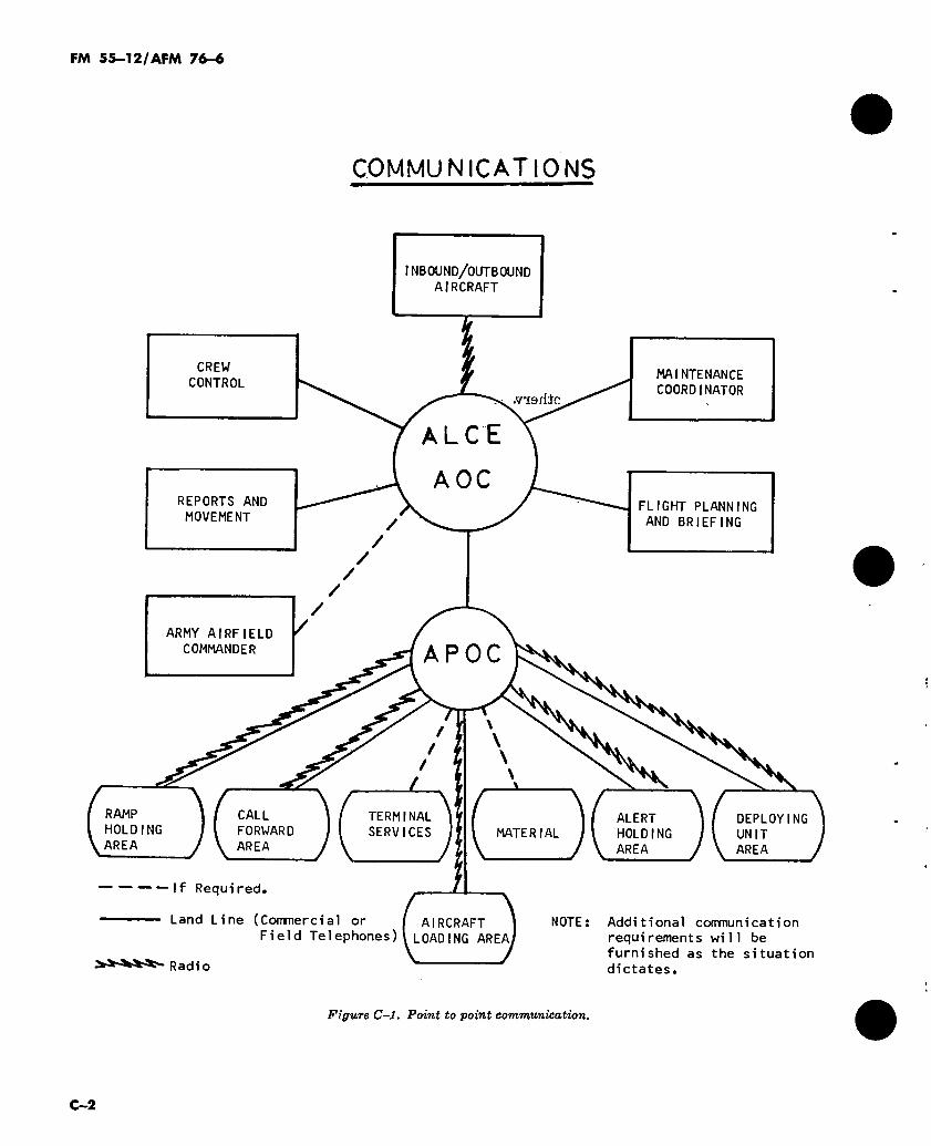
Figure C-l illustrates point to point communications from the airlift operations center to each area of activity in a joint airlift operation.
■IJ 'ieh: fc
C-l
FM 55-12/AFM 76-6
COMMUNICATIONS
INBOUND/OUTBOUND
AIRCRAFT
CREW
CONTROL MAINTENANCE
COORDINATOR .via nie
ALCE
A OC REPORTS AND
MOVEMENT FLIGHT PLANNING
AND BRIEFING
/ /
/
ARMY AIRFIELD
COMMANDER P A
CALL
FORWARD
AREA
TERMINAL
SERVICES ALERT
HOLDING
AREA
DEPLOYING
UNIT
AREA
MATERIAL
NOTE
RAMP
HOLDING
AREA
——If Required.
Land Line (Commercial or [ AIRCRAFT i
Field Telephones)l LOADING AREAJ
Radio
Additional communication
requirements will be
furnished as the situation
dictates.
Figure C—l. Point to point communication.
C—2
FM 55-12/AFM 76-6
APPENDIX D
SAFETY CHECKLIST FOR VEHICLE OPERATIONS
1. All vehicles and equipment will be inspected in the marshaling area for proper fuel levels and mechanical defects.
2. No vehicle will be driven under any part of the aircraft (fig D-l).
3. Chocks will be used to the front and rear of one wheel of any vehicle stalled or otherwise stop- ped on a aircraft loading ramp.
4. Maximum speeds for all vehicles within 50 feet of any aircraft will be five miles per hour (MPH).
5. All unattended vehicles will have the engine shut down, gears positioned for holding the vehi- cle, and the hand brake set. Keys must be left in the ignition of unattended vehicles.
6. No vehicle other than those onloading or off- loading will be driven directly towards or parked closer than 25 feet from an aircraft.
7. Vehicles will not be backed in the vicinity of the aircraft without a walking guide observing clearance for the driver.
8. Only one person will provide signal guidance for vehicle operations while vehicles are onload- ing or offloading from the aircraft. Vehicle drivers/equipment operators will follow the in- structions of the individual designated by the primary loadmaster while onloading and offload- ing the aircraft.
9. All vehicle/equipment guides will stay clear of operating vehicles/equipment.
10. All safety chains and pintle hook pins will be installed on vehicles towing trailers.
11. Vehicles on the cargo floor will not be left unattended until a minimum of one chain is placed to provide both forward and aft restraint.
12. General safety considerations (AFM 127- 101).
a. There will be no smoking on the aircraft parking ramp except in designated smoking zones.
b. Personnel 'will not sit or lie on the ramp, under vehicles, aircraft, or equipment.
c. Rings or watches should not be worn by members of loading/offloading teams.
d. No equipment such as tie down chains, chocks, wrenches, etc., will be thrown about the aircraft.
e. No equipment will be refueled or other wise serviced within 50 feet of an aircraft.
/. Fire bottles will be positioned for all power- ed equipment used in conjunction with an air- craft.
13. Special C-5 safety considerations, T.O. 1C- 5A-1.
a. When jet engines are running, personnel and equipment must not approach within 50 feet of an engine intake nor within 200 feet in the blast area to the rear.
b. Noise levels in and around the C-5 cargo compartment make use of ear protection manda- tory during operation of engines or aircraft auxi- liary power equipment.
c. All loose equipment such as chocks, plank- ing, maintenance stands, etc., must be removed from any area that will be affected by blast from aircraft taxiing out of a parking position. Wind blast velocities exceeding 35 MPH can be expect- ed within 500 feet aft of the engmes. Velocities at 200 feet will approximate 70 MPH.
d. Fire bottles are available along the side walls of the C-5 cargo compartment should they be needed (T.O. 1C-5A-1).
e. Care must be used in movement around open doors and hatches and on the loading ramp of the cargo compartment (T.O. 1C-5A-1). Cargo floor level in an unkneeled pos'tion is nine feet from ground level.
D-l

For Front Loaded Aircraft
10 ft 10 ft.
10 ft 10 ft
0 ft
10 ft. 10 ft.
-> —► —-» —t Ik-.= =*. = =;s. ► Authorized approach to the aircraft.
=5*— Authorized exit path from the aircraft.
10 ft.
Figure D-l. Safety perimeter and vehicle access routes to transport aircraft.
m S
5-12/AF
M 76-6
FM 55-12/AFM 76-6
APPENDIX E
UNIT MOVEMENT OFFICER
E-T. Unit Movement Officer (UMO) In each company size air transportable unit, it is recommended that a UMO be appointed. A senior noncommissioned officer may be appointed as his assistant. These two individuals should be service school or unit trained and thoroughly conversant with:
a. Air Force organization and terminology.
b. The air transportability of the TOE equip- ment of his unit.
c. Characteristics and capabilities of the type of aircraft which his unit may employ in an air- lift.
E-2. Duties of the UMO The duties of the UMO are as follows:
a. Acts as representative of the transported unit commander.
b. Supervises air movement training of the unit.
c. Prepares necessary air movement plans.
d. Coordinates and supervises marshaling and outloading of the unit.
e. Effects liaison with the DACG.
/. Assists in offloading and reassembling of the unit at the arrival airfield.
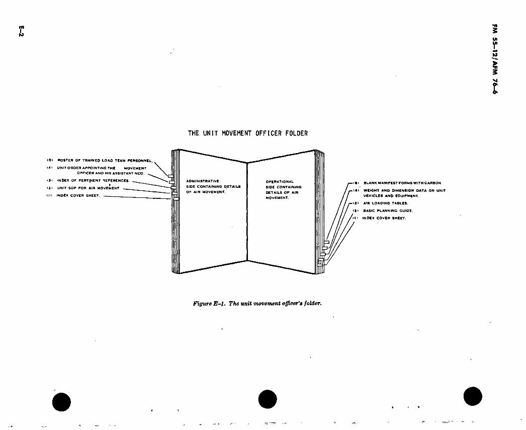
g. Maintains a current UMO FOLDER (fig E-l).
h. Prepares necessary airlift forms such as the basic planning guide, aircraft loading tables, aircraft load checklists, and air movement tables.
i. Inspects manifests for accuracy.
j. Coordinates necessary communications.
k. Keeps commander informed of all aspects of operation.
l. Insures that the Aircraft Load Checklists contain the following:
(1) Plane Chalk No. Type Air- craft
(2) Proper vehicles in load. (3) Vehicles marked with chalk number of
aircraft. (4) Vehicles marked with center of gravity
and weight. (5) Vehicles loaded properly. (6) Drivers briefed. (7) Canvas secured. (8) Gas tank not more than 3/4 full. (9) Troops (how many).
(10) Condition of vehicles (no oil or fuel leaks).
(11) Troops properly equipped and briefed on emergency and safety procedures.
E-3. Unit Movement Officer Folder Each UMO should maintain a folder containing the necessary documents required for an air move- ment. The folder is divided into two sections, an administrative and an operational side, as illustrated in figure E-l.
a. The administrative section contains the fol- lowing:
(1) Index cover section. (2) Company order appointing the UMO
and NCO assistant. (3) Roster of trained load team personnel. (4) Unit SOP for air movement including
notes from previous operations.
b. The operational section contains the follow- ing:
( 1 ) Index cover sheet. (2) Air movement and manifest forms. (3) Weight and dimensions data on unit
vehicles and equipment. (4) Data on Air Force and Army aircraft. (5) Data on sling loads, lowering devices,
cargo containers, and air delivery items related to air movement.
E-l
S)
THE UNIT MOVEMENT OFFICER FOLDER
(9)
(4)
«3»
• 2»
INDEX Of PERTINENT REFERENCES. «
UNIT SOP FOR AIR MOVEMENT
(I) INDEX COVER SHEET. m
ROSTER OF TRAINED LOAD TEAM PERSONNEL.
UNIT ORDER APPOINTING THE MOVEMENT OFFICER AND HIS ASSISTANT NCO.
ADMINISTRATIVE
SIDE CONTAINING DETAILS OF AIR MOVEMENT.
OPERATIONAL
SIDE CONTAINING
DETAILS OF AIR
MOVEMENT.
(ft) BLANK MANIFEST FORMS WITH CARBON
4» WEIGHT AND DIMENSION DATA ON UNIT
VEHICLES AND EQUIPMENT.
9) AIR LOADING TABLES.
21 BASIC PLANNING GUIDE.
It INDEX COVER SHEET.
Figure E-Î. The unit movement officer's folder.
y- -
FM
55
—1
2/A
FM 76-6
FM 55-12/AFM 76-6
APPENDIX F
LOAD PLANNING
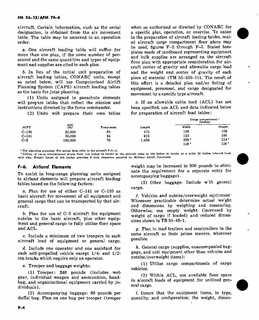
F-l. Loading Plan a. The loading plan formulated in joint con-
ferences contains information regarding the total number of personnel and the total amount of equipment to be airlifted, the allowable cargo loads, and the general sequence of movement.
b. Load planning permits adjustment to con- form with changes in the number and type of aircraft and variations in the allowable cabin load for individual aircraft.
c. There are two types of aircraft loading for unit moves, combat; loading and unit loading.
(1) Combat loading requires the arrange- ment of personnel and the stowage of equipment and supplies in a manner designed to conform to the anticipated tactical operation of the organiza- tion embarked. Each individual item is stowed so that it can be offloaded at the required time.
(2) Unit loading requires the loading of troop units with their equipment and supplies in the same aircraft.
(a) In unit loading, the sequence of loading, as well as preparation of equipment for loading, is directed toward effective utilization of transport aircraft and expedited delivery of the force to the objective area.
(b) Unit integrity is maintained to the extent feasible, but when rigid adherence to unit integrity or maintenance of a particular se- quence of items will increase the number of air- craft required, the requirement for efficient, economical use of transport aircraft must govern.
(3) Frequently it is necessary to insure ex- pedited offloading of transported equipment at the destination air base. This requirement may be due to airfield saturation, danger to the air- craft, need to conserve aircrew time, or the short total time available for delivery of the en- tire force. To expedite offloading in such cases, efficient utilization of aircraft may be sacrificed by the following procedures:
(a) Trailers will remain coupled to prime movers.
(b) No cargo, other than accompanied baggage of passengers on each aircraft, will be loaded on the floor or ramp of aircraft carrying wheeled or tracked vehicles, vehicle mounted equipment or aircraft.
(c) Vehicles will be loaded on the air'raft facing the exit ramp.
F-2. Responsibilities
a. The transporting unit commander is respon- sible for:
(1) Jointly with the transported unit com- mander, developing the load plans.
(2) Establishing and disseminating instruc- tions for documenting and manifesting all traf- fic.
(3) Providing instructions for loading and offloading of aircraft and for cargo tiedown.
(4) Parking mission aircraft in accordance with the parking plan.
(5) Configuring mission aircraft in accord- ance with the air loading plan.
(6) Providing loading ramps, aircraft equipment for aeromedical evacuation of casul- ties, floor conveyors, tiedowns and other auxiliary equipment.
(7) Insuring that transported unit person- nel have safety belts fastened and are briefed on emergency and safety procedures prior to take- off.
(8) Providing technical assistance to per- sonnel engaged in loading, tying down, or off- loading aircraft.
(9) Verifying the documentation of person- nel and equipment loaded on aircraft.
(10) Furnishing and operating materials handling equipment required in aircraft loading and offloading at all sites when such equipment or suitable substitute normally is not organic to the shipping unit, the transported unit, or the unit accepting delivery.
F-l

FM 55-12/AFM 76-6 i
b. The transported unit commander is respon- sible for:
(1) Establishing the priority and sequence for the movement of transported unit personnel, equipment, and supplies.
(2) Preparing of aircraft loading table to incorporate his priority for movement and to in- clude provision for all personnel, equipment, and supplies that constitute his unit configured for the specific mission, and for coordination of the planned aircraft loads with the transporting unit commander.
(3) Preparing cargo for air movement. (4) Marking each major item of equipment
to show weight, and when appropriate, the center of gravity.
(5) Documenting and manifesting all loads of transported unit personnel, equipment, and supplies.
(6) Directing, monitoring, and accomplish- ing the movement of ground traffic to the depar- ture airfield or loading area and accepting de- livery at destination.
(7) Deliverying properly packaged supplies and equipment to the aircraft in accordance with the loading plan.
(8) Loading, tying down, and offloading supplies and equipment under the technical su- pervision of transporting unit personnel.
(9) Briefing and supervising transported unit vehicle operators to insure a thorough under- standing t>f airfield traffic procedures and safety precautions to be observed while driving around and near aircraft.
(10) Providing loading teams and vehicles to offload aborting aircraft and reload onto spare aircraft.
(11) Insuring that the transported unit per- sonnel are seated in the aircraft with seatbelts fastened, prepared for flight and available for briefing at the designated airborne station time.
(12) Providing required shoring for vehicles and equipment for loading or to protect aircraft floors.
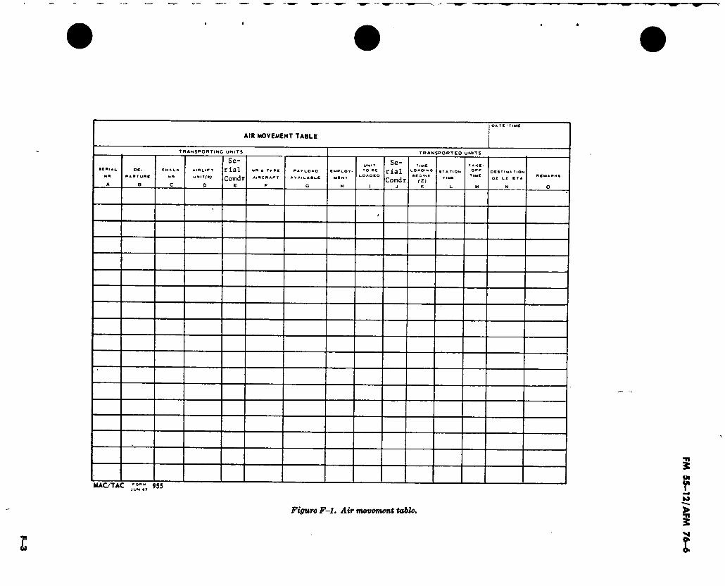
F—3. Air Movement Table (Fig F—1) The air movement table is a form prepared joint- ly by the commanders of the transporting and transported units and is annexed to the operation order. It allocates aircraft to the units to be lifted. It designates the number and type of air-
craft in each serial and specifies the departure sites, time of loading, station time, takeoff time, and destination for each serial.
F-4. Explanation of Air Movement Table Heading: Completed by the headquarters pre- paring the form.
Column A: A number given to a group of aircraft, under one commander, conveying a unit or subunit to one DZ, LZ, or airfield.
Column B: The designation of the departure site as decided by the transporting and trans- ported units.
Column C: Information to be provided by the transporting unit.
Column D: Designation of the transporting unit.
Column E: Transporting unit serial com- mander’s name and rank.
Column F: Total number and type of air- craft for each serial.
Column G: Payload available (passengers and cargo).
Column H: Mode of entry into objective areas, parachute, assault aircraft or airlanded.
Column I: Designation of the unit to be load- ed.
Column J: Transported unit serial comman- der’s name.
Column K: Self-explanatory. Column L: Time (Z), establish by trans-
porting unit when personnel and equipment must be loaded in aircraft, prepared for departure. A minimum time prior to take off is desirable.
Column M: Self-explanatory. Column N: Name or designation of the land-
ing area as determined in the operational plan and estimated time of arrival.
Column 0: Remarks. General: The information in columns K, L,
and M is normally determined separately for each departure site by the transporting unit.
F-5. Aircraft Loading Table (Fig F—2) The aircraft loading table is a data sheet pre- pared by or for the commander of each trans- ported unit. It is transmitted to the transporting force commander as the basis for joint load planning. Following concurrence by the transport- ing unit, the table becomes the basis for prepara- tion of manifests. The form lists the load pro- posed by the unit or force commander for each
F-2
OA TC ' T IMC
AIR MOVEMENT TABLE
acftiAi NM
TRANSPORTING UNITS
OC*
PAMTuMf UNI
0
Se- rial Corad r
NM i TT PC
AlMC M APT
P A Y L O A O
AVAICABLC
TRANSPORTED UNITS
EMPLOY
MENT
UNI T ▼O BE
» O A O E O
Se- rial Corad r
TIME LOADING
BEGINS
<Z)
STA TION
TIME
TAKE- OFF
TIME DESTINA T|ON
OZ LZ ETA
MAC/TAC ,ro"“ 95S JU- «T
Figure F-l. Air movement table.
I
FM
55
-12
/AF
M 7
6-«
FM 55-12/AFM 76-6
aircraft. Certain information, such as the serial designation, is obtained from the air movement table. The table may be annexed to an operation order.
a. One aircraft loading table will suffice for more than one plan, if the same number of per- sonnel and the same quantities and types of equip- ment and supplies are cited in each plan.
b. In lieu of the initial unit preparation of aircraft loading tables, CONARC units, except as noted below, will use Computerized Airlift Planning System (CAPS) aircraft loading tables as the basis for joint planning.
(1) Units assigned to parachute elements will prepare tables that reflect the mission and instructions directed by the force commander.
(2) Units will prepare their own tables
when so authorized or directed by CONARC for a specific plan, operation, or exercise. To assist in the preparation of aircraft loading tables, scal- ed aircraft cargo compartment floor plans may be used, figures F-3 through F-5. Scaled tem- plates made of cardboard representing equipment and bulk supplies are arranged on the aircraft floor plan with appropriate consideration for air- craft center of gravity and allowable cargo load and the weight and center of gravity of each piece of material (TM 55-450-15). The result of this effort is a detailed plan and/or listing of equipment, personnel, and cargo designated for movement by a specific type aircraft.
c. If an allowable cabin load (ACL) has not been specified, use ACL and data indicated below for preparation of aircraft load tables:
ACFT
C-130 C-141 C-5
ACL (lb)
25.000 50.000
180,000
Troop eeato
64 94 73
Cargo compartment1
(inches)
Length
470 810
1,452
Width
109 123 228 2
156 2
Height
106 106 114 2
1562
1 For planning purposes. For actual data refer to the aircraft T.O.-9.
2 Ceiling of cargo compartment slants from 114 inches in height at the aircraft sides to 162 inches in height at a point 36 inches inboard from
each side. Height figure of 156 inches provides 6 inch clearance required by Military Airlift Command.
F—6. Airland Elements To assist in long-range planning units assigned to airland elements will prepare aircraft loading tables based on the following factors:
а. Plan for use of either C-141 or C-130 as basic aircraft for movement of all equipment and general cargo that can be transported by that air- craft.
б. Plan for use of C-5 aircraft for equipment outsize to the basic aircraft, plus other equip- ment and general cargo to fully utilize floor space and ACL.
c. Include a minimum of two troopers in each aircraft load of equipment or general cargo.
d. Include one operator and one assistant for each self-propelled vehicle except 1/4- and 1/2- ton trucks which require only an operator.
e. Trooper and baggage weights: (1) Trooper: 240 pounds (includes web
gear, individual weapon and ammunition, hand- bag, and organizational equipment carried by in- dividuals).
(2) Accompanying baggage: 60 pounds per duffel bag. Plan on one bag per trooper (trooper
weight may be increased to 300 pounds to elimi- nate the requirement for a separate entry for accompanying baggage).
(3) Other baggage: Include w'th general cargo.
/. Vehicles and outsize/overweight equipment- Whenever practicable determine actual we'ght and dimensions by weighing and measuring. Otherwise, use empty weight (increased by weight of cargo if loaded) and reduced dimen- sions shown in TB 55-46-1.
g. Plan to load trailers and semitrailers in the same aircraft as their prime movers, wherever possible.
h. General cargo (supplies, unaccompanied bag- gage, and unit equipment other than vehicles and outsize/overweight items) :
(1) Utilize cargo compartments of cargo vehicles.
(2) Within ACL, use available floor space in aircraft loads of equipment for unitized gen- eral cargo.
i. Insure that the equipment items, in type, quantity, and configuration; the weight, dimen-
F-4
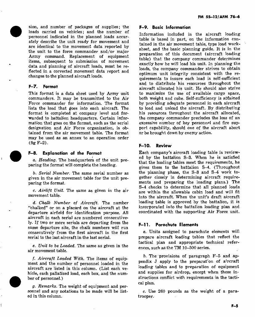
FM 55-12/AFM 76-6
sion, and number of packages of supplies; the loads carried on vehicles; and the number of personnel indicated in the planned loads accur- ately describe the unit ready for movement and are identical to the movement data reported by the unit to the force commander and/or major Army command. Replacement of equipment items, subsequent to submission of movement data and planning of aircraft loads, must be re- flected in a corrected movement data report and changes to the planned aircraft loads.
F-7. Format This format is a data sheet used by Army unit commanders. It may be transmitted to the Air Force commander for information. The format lists the load that ¿oes into each aircraft. The format is completed at company level and for- warded to battalion headquarters. Certain infor- mation that goes on the format, such as the serial designation and Air Force organization, is ob- tained from the air movement table. The format may be used as an annex to an operation order (fig F-2).
F-8. Explanation of the Format !
a. Heading. The headquarters of the unit pre- paring the format will complete the heading.
b. Serial Number. The same serial number as given in the air movement table for the unit pre- paring the format.
c. Airlift Unit. The same as given in the air movement table.
d. Chalk Number of Aircraft. The number "chalked” or on a placard on the aircraft at the departure airfield for identification purpose. All aircraft in each serial are numbered consecutive- ly. If two or more serials are departing from the same departure site, the chalk numbers will run consecutively from the first aircraft in the first serial to the last aircraft in the last serial.
e. Unit to be Loaded. The same as given in the air movement table.
f. Aircraft Loaded With. The items of equip- ment and the number of personnel loaded in the aircraft are listed in this column. (List each ve- hicle, each pallatized load, each box, and the num- ber of personnel.)
g. Remarks. The weight of equipment and per- sonnel and any notations to be made will be list- ed in this column.
F—9. Basic Information
Information included in the aircraft loading table is based in part, on the information con- tained in the air movement table, type load work- sheet, and the basic planning guide. It is in the preparation of this document (aircraft loading table) that the company commander determines exactly how he will load his unit. In planning the loads, the company commander strives to obtain optimum unit integrity consistent with the re- quirements to insure each load is self-sufficient and to distribute his resources throughout the aircraft allocated his unit. He should also strive to maximize the use of available cargo space, both weight and cube. Self-sufficiency is attained by providing adequate personnel in each aircraft to load and unload the aircraft. By distributing his resources throughout the aircraft allocated, the company commander precludes the loss of an excessive number of key personnel and fire sup- port capability, should one of the aircraft abort or be brought down by enemy action.
F—10. Review
Each company’s aircraft loading table is review- ed by the battalion S-3. When he is satisfied that the loading tables meet the requirements, he gives them to the battalion S-4. (Throughout the planning phase, the S-3 and S-4 work to- gether closely in determining aircraft require- ments and preparing the loading plans.) The S-4 checks to determine that all planned loads are within the allowable cabin load and will fit into the aircraft. When the unit’s draft aircraft loading table is approved by the battalion, it is incorporated into the battalion loading plan and coordinated with the supporting Air Force unit.
F-l 1. Parachute Elements
a. Units assigned to parachute elements will prepare aircraft loading tables that reflect the tactical plan and appropriate technical refer- ences, such as the TM 10-500 series.
b. The provisions of paragraph F-5 and ap- pendix J apply to the prepararon of aircraft loading tables and to preparation of equipment and supplies for airdrop, except when those in- structions conflict with requirements in the tacti- cal plan.
c. Use 260 pounds as the weight of a para- trooper.
F-5
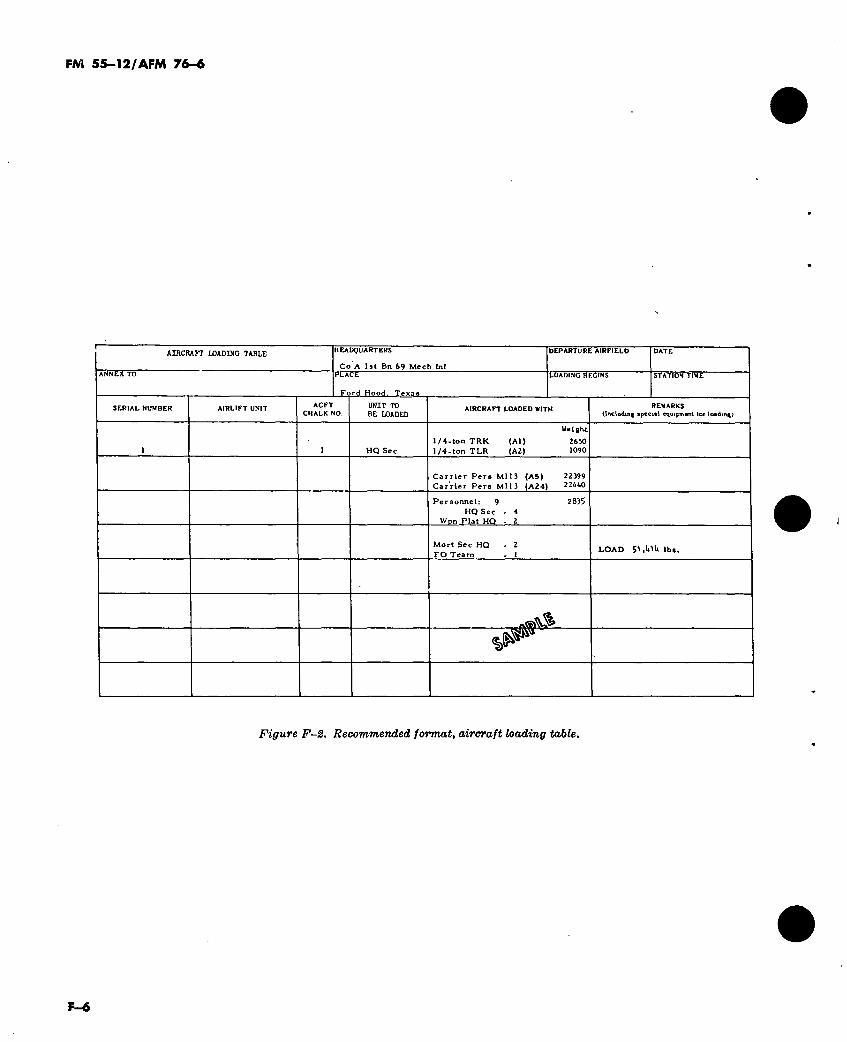
FM 55-12/AFM 76-6
AIRCRAFT LOADING TABLE HEADQUARTERS
Co A 1 st Bn 69 Mech Inf
DEPARTURE AIRFIELD
PLACE
Ford Hood. Texas
T.ÓADLNG BEGINS STATION TINE
SERIAL NUMBER AIRLIFT UNIT ACFT CHALK NO.
UNIT TO BE LOADED
AIRCRAFT LOADED WITH REMARKS (Including *p«ci*l equipment tor loading)
HQ Sec
1/4-tonTRK (Al)
1 /4-ton TLR (A2)
Weight
2630 1090
Carrier Pera M113 (A5)
Carrier Pera MU3 (A24)
22399 22440
Personnel: 9
HQ Sec
Wpn Plat HQ
2835
Mort Sec HQ - 2
FO Team - 1 LOAD Sl.llltllbs.
Figure F-2. Recommended format, aircraft loading table.
F—6
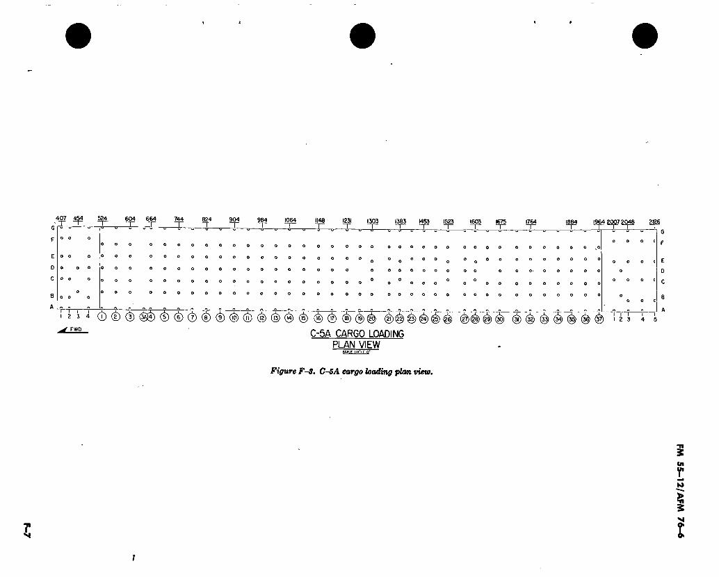
F-7
407 454 524 604 664 744 904 984 1064 1148 1231 1303
o o o o o
o o o o o
o o o
o o
o o o
12 3 4 10 II 12 13 IW) 15) 16) 17 19) 2
1383 1453 1523 1675 1764 1884
^ FWP
(2Í)(^l^ ^)(g)(g) (í) ^ í^)"^) (^) (^)
C-5A CARGO LOADING
PLAN VIEW
2126 1964 2007 2048
I 2 3
Figure FS. C-5A cargo loading plan view.
f
FM 5
5-1
2/A
FM 7
6-6
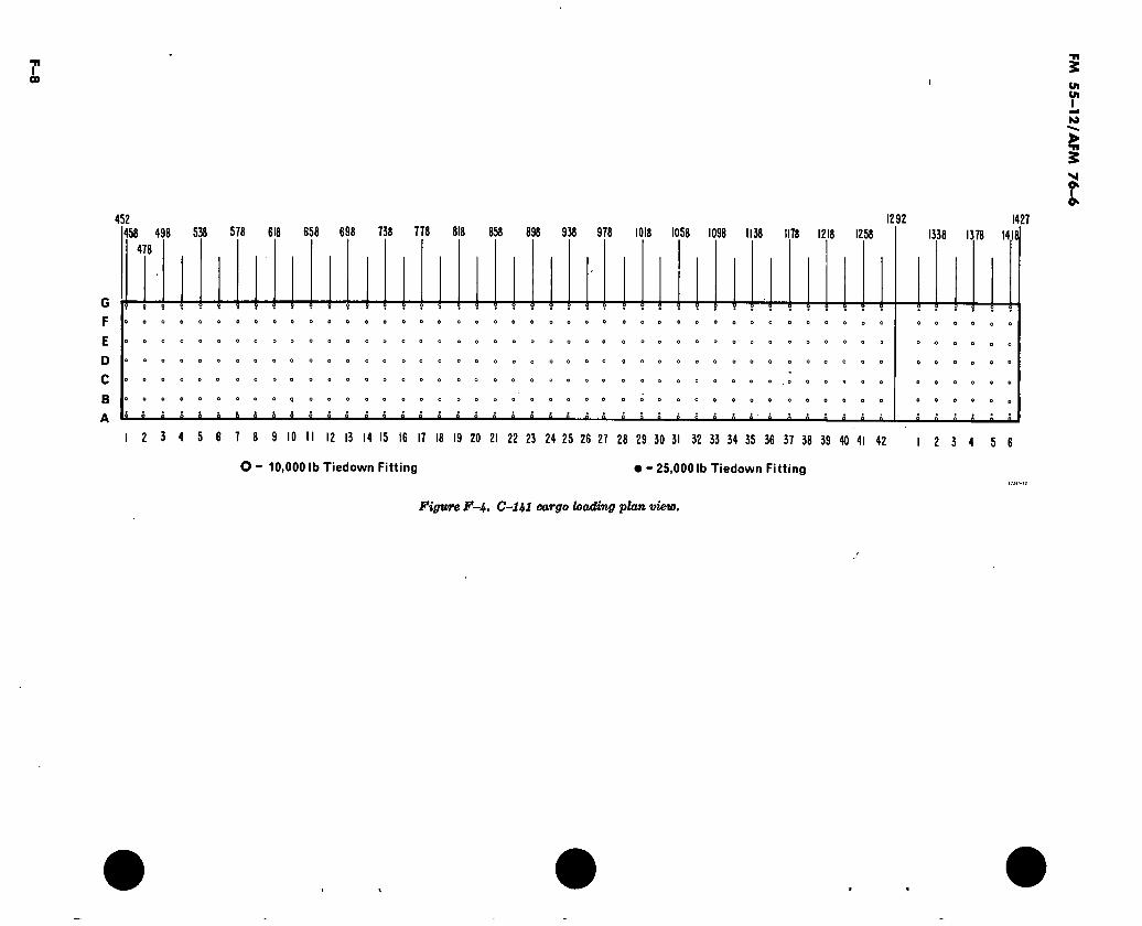
T 00 I
452 458 498 538
478
G
F
E
D
C
B
578 618 658 698 738 778 818 858 938 978 1018 1058 1098 1138 1178 1218 1258 1292 1427
1338 1378 1418
-i—¡—£—£—à—£—£—£—£—£——£—£ £ £ £ » i à £
O o O
“8"
O O
° O O O O O
O O O 9 0 0
0 0 O O O O
O O O O o O
I 2 3 4 5 6 7 8 9 10 II 12 13 14 15 16 17 18 19 20 21 22 23 24 25 26 27 28 29 30 31 32 33 34 35 36 37 38 39 40 41 42
O - 10,000 lb Tiedown Fitting • - 25,000 lb Tiedown Fitting
2 3 4 5 6
Figure F-i. C-Hl cargo loading plan view.
FM 5
5-1
2/A
FM 7
6-6
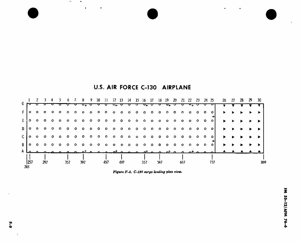
F-9
U.S. AIR FORCE C-130 AIRPLANE
G
F
E
D
C
B
A
1 2 3 4 5 6 7 .8 9 10 11 12 13 14 15 16 17 18 19 20 21 22 23 24 25 26 27 28 29 30
o o
o o
o o
o o
o o
257 245
TJ O' U
O O O
O O O
o o o
o o o
o o o
Li U U4. U U (J U4. U U U
OOOO
297 357
—o—o^-o—cr—erq
o o
o o
o o
o o
o o
o o
o o
o o
397 457 497 557 597 657
Figure F-5. C-1S0 cargo loading plan view.
-O—0-1
OOOOOOOOOOOOOOOO
OOOOOOOOOOOOOOOO
OOOOOOOOOOOOOOOO
OOOOOOOOOOOOOOOO
+ OOOOOOOOOOOOOOOO
737
▼ ▼ ▼ T ▼
► ► ► ► ►
► ► ► ► ►
► ► ► ► ►
► ► ► ► ►
► ► ► ► ►
▲
869
FM 5
5-1
2/A
FM 76-6

I
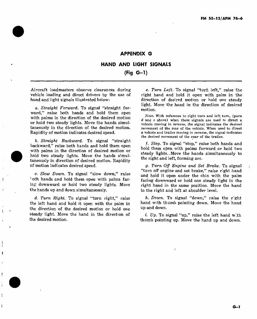
FM 55-12/AFM 76-«
APPENDIX G
HAND AND LIGHT SIGNALS
(Fig G-l)
Aircraft loadmasters observe clearances during vehicle loading and direct drivers by the use of hand and light signals illustrated below:
a. Straight Forward. To signal “straight for- ward,” raise both hands and hold them open with palms in the direction of the desired motion or hold two steady lights. Move the hands simul- taneously in the direction of the desired motion. Rapidity of motion indicates desired speed.
h. Straight Backward. To signal “straight backward,” raise both hands and hold them open with palms in the direction of desired motion or hold two steady lights. Move the hands simul- taneously in direction of desired motion. Rapidity of motion indicates desired speed.
c. Slow Down. To signal “slow down,” raise ^'Oth hands and hold them open with palms fac- ing downward or hold two steady lights. Move the hands up and down simultaneously.
d. Turn Right. To signal “turn right,” raise the left hand and hold it open with the palm in the direction of the desired motion or hold one steady light. Move the hand in the direction of the desired motion.
e. Turn Left. To signal “turn left,” raise the right hand and hold it open with palm in the direction of desired motion or hold one steady light. Move the hand in the direction of desired motion.
Note. With reference to right turn and left turn, (para d and e above) when these signals are used to direct a vehicle moving in reverse, the signal indicates the desired movement of the rear of the vehicle. When used to direct a vehicle and trailer moving in reverse, the signal indicates the desired movement of the rear of the trailer.
f. Stop. To signal “stop,” raise both hands and hold them open with palms forward or hold two steady lights.-Move the hands simultaneously to the right and left, forming arc.
p. Turn Off Engine and Set Brake. To signal “turn off engine and set brake,” raise right hand and hold it open under the chin with the palm facing downward or hold one steady light in the right hand in the same position. Move the hand to the right and left at shoulder level.
h. Down. To signal “down,” raise the rght hand with thumb pointing down. Move the hand up and down.
i. Up. To signal “up,” raise the left hand with thumb pointing up. Move the hand up and down.
>
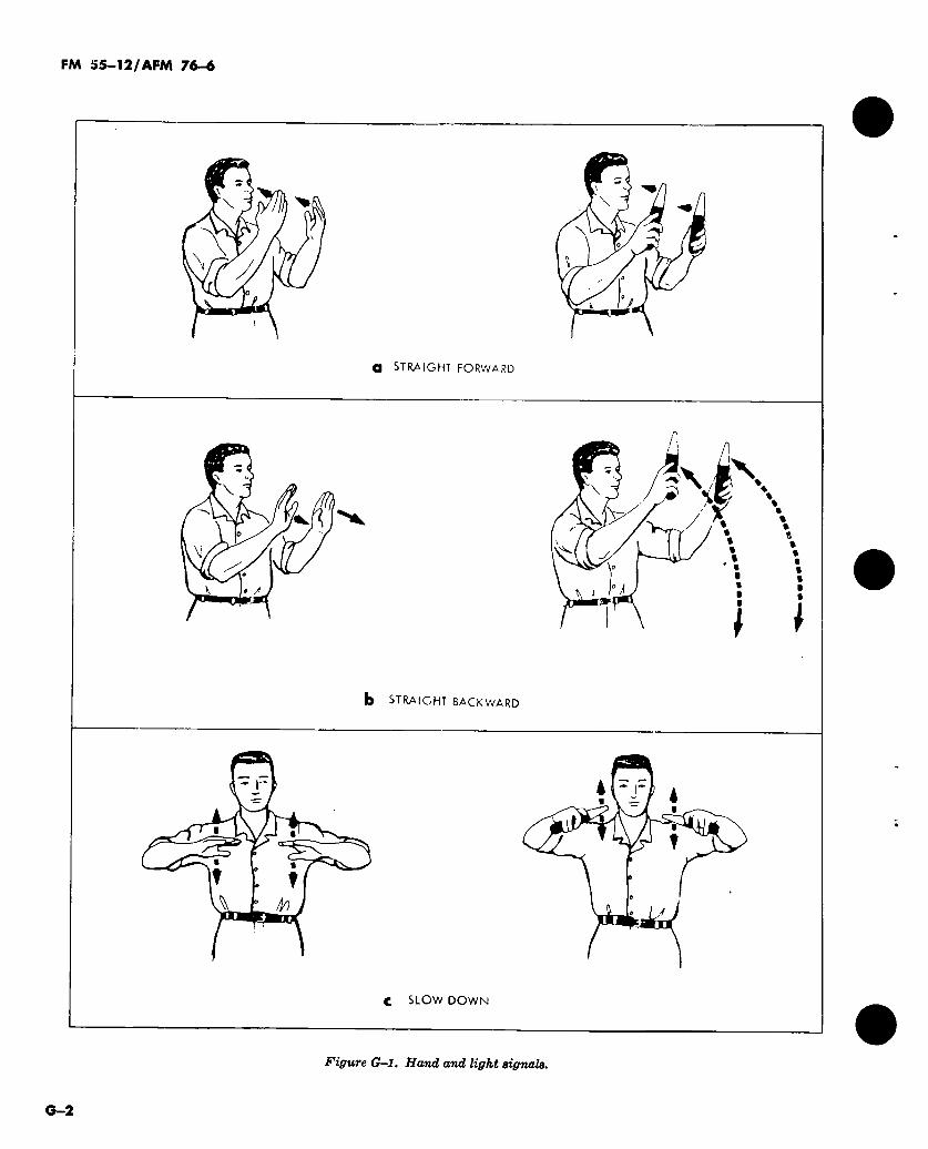
FM 55-12/AFM 76-6
U
a STRAIGHT FORWARD
V à \E N
%
i I b ST RA IG FIT BACKWARD
40 ‘ I A
c SLOW DOWN
Figure G—l. Hand and light signala.
G—2
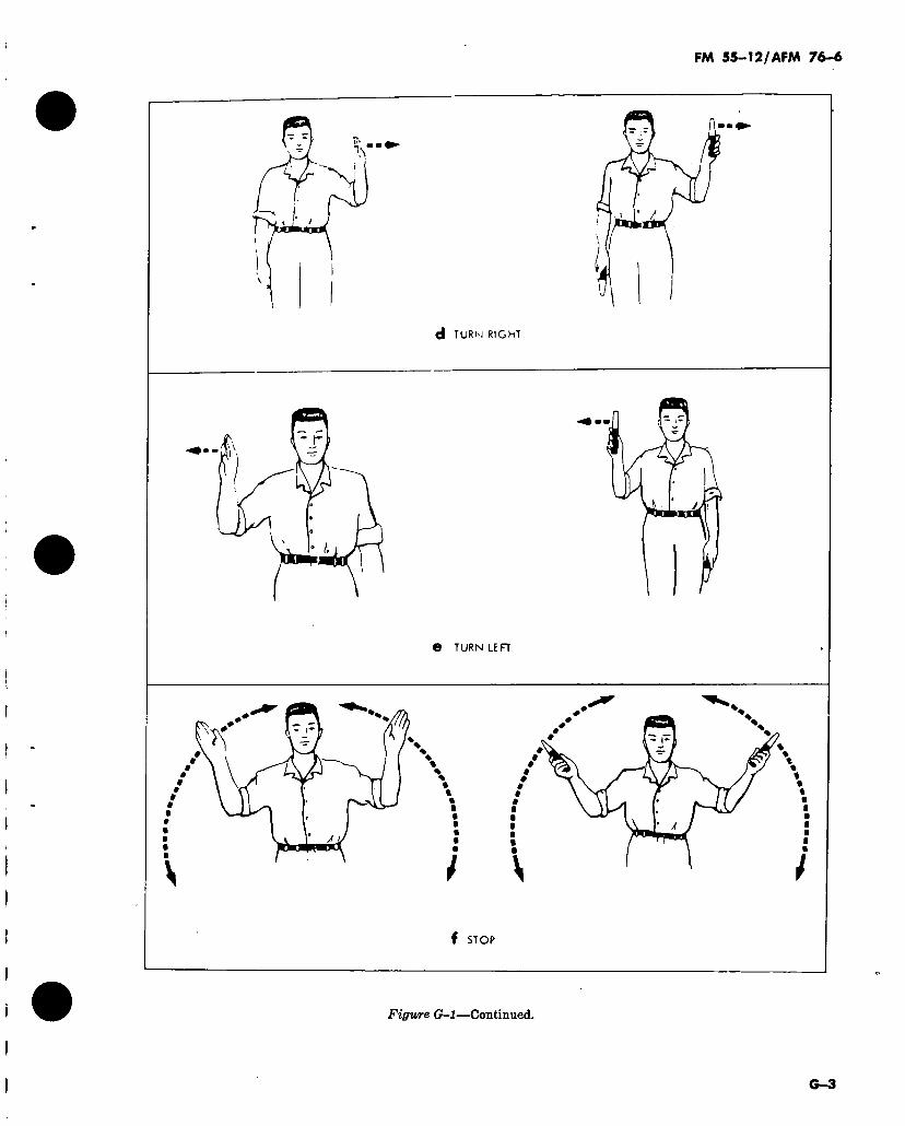
FM 55-12/AFM 76-6
d TURN RIGHT
e TURN LE R
\
f STOP
Figure G-l—Continued.
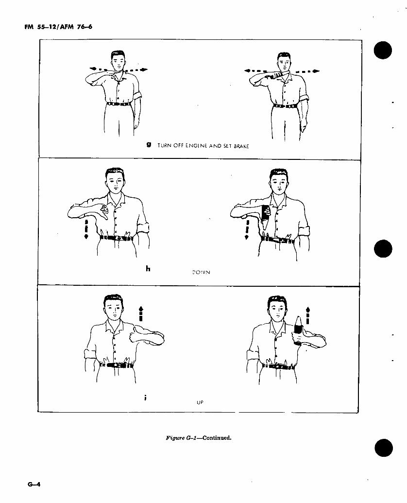
FM 55—12/AFM 76-6
9 TURN OFF ENGINE AND SET BRAKE
r
t ^ a
DOWN
: ^7^3 (A
UP
Figure G-l—Continued.
G—4
FM 55-12/AFM 76-6
APPENDIX H
TRANSPORTED ARMY UNIT LIAISON DETACHMENTS
H-1. Departure Airfield, Unit Liaison Officers (Fig H-1)
a. Unit Liaison Detachment Commander/As- sistant Detachment Commander.
(1) Represents the unit commander at the departure airfield. «
(2) Assists the CO of the DACG. (3) Briefs all personnel assigned to the unit
DACG liaison detachment. (4) Coordinates, supervises, and controls
the unit liaison detachment. (5) Coordinates use of DACG communica-
tions to the unit, and establishes additional means when required.
h. Unit Liaison Assistant Detachment Com- mander/Operations Officer. Principal assistant to the detachment commander and responsible to the detachment commander for the expeditious processing of the unit through the departure airfield.
(1) Informs the unit of changes to planned movement.
(2) Provides detachment commander with vehicle traffic flow plan.
(3) Insures communications are operation- al.
(4) Informs detachment statistics officer of any changes to movement plan which may affect accurate reporting.
c. Alert Holding Area Liaison Officer.
(1) Is the chief assistant to the operations officer.
(2) Relays to the unit liaison detachment commander any instructions received from the alert holding area control officer.
(3) Issues special instructions, received from the alert holding area control officer, to alerted planeload commander.
(4) Expedites movement of aircraft loads
from the unit marshaling area to the alert hold- ing area.
d. Detachment Statistics/Administrative Liai- son Officer.
(1) Is responsible to the liaison detach- ment commander for providing required data to the DACG statistics officer on which to base re- ports required by higher headquarters.
(2) Notifies DACG administrative officer of any incidents/accidents at the departure airfield.
(3) Coordinates with DACG administra- tive officer, for use of personal services provided by the Air Force base.
e. Logistics Liaison Officer. Responsible to the detachment commander for coordinating with the DACG logistics officer for the location and use of:
(1) Water supply points. (2) Medical facilities. (3) Latrine and shower facilities. (4) Fuel supply and fuel drainage area. (5) Billeting. (6) Materials handling equipment. (7) Messing facilities. (8) Laundry facilities.
H-2. Arrival Airfield, Unit Liaison Officers
a. Unit Liaison Detachment Commander.
(1) Represents the unit commander at the arrival airfield.
(2) Assumes control of planeloads from AACG.
(3) Briefs all personnel assigned to the unit AACG liaison detachment.
(4) Coordinates, supervises, and contro’s the unit liaison detachment.
(5) Establishes communication as required.
h. Unit Liaison Assistant Detachment Com-
H—1
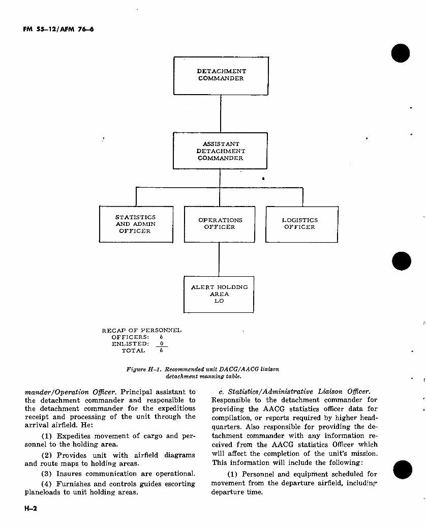
FM 55-12/AFM 76-6
DETACHMENT COMMANDER
ASSISTANT DETACHMENT COMMANDER
STATISTICS AND ADMIN OFFICER
OPERATIONS OFFICER
LOGISTICS OFFICER
ALERT HOLDING AREA
LO
RECAP OF PERSONNEL OFFICERS: 6 ENLISTED: 0
TOTAL 6
Figure H-l. Recommended unit DACG/AACG liaison detachment manning table.
mander/Operation Officer. Principal assistant to the detachment commander and responsible to the detachment commander for the expeditious receipt and processing of the unit through the arrival airfield. He:
(1) Expedites movement of cargo and per- sonnel to the holding area.
(2) Provides unit with airfield diagrams and route maps to holding areas.
(3) Insures communication are operational. (4) Furnishes and controls guides escorting
planeloads to unit holding areas.
c. Statistics/Administrative Liaison Officer. Responsible to the detachment commander for providing the AACG statistics officer data for compilation, or reports required by higher head- quarters. Also responsible for providing the de- tachment commander with any information re- ceived from the AACG statistics Officer which will affect the completion of the unit’s mission. This information will include the following:
(1) Personnel and equipment scheduled for movement from the departure airfield, including departure time.
H-2
FM 55-12/AFM 76-6
(2) Names of Army personnel killed, injured, or hospitalized.
d. Logistics Liaison Officer.
(1) Responsible to the detachment com- mander for coordinating logistic requirements of the unit at the arrival airfield.
(2) Coordinates with AACG logistics of-
ficer for required ground transportation to move unit from the arrival airfield.
(3) Coordinates use of materials handling equipment.
(4) Coordinates with the Logistics AACG officer for maintenance support of unit vehicles which have become disabled after arrival at the airfield.
H-3


FM 55-12/AFM 76-6
APPENDIX I
VEHICLE INSPECTION CHECKLIST
1-1. Vehicle Inspection Checklist This checklist is intended as a guide only and does not relieve the user of responsibilities for appropriate vehicle preparations contained in TM 55-450-15 and TM 38-250/AFM 71-4.
a. Cleanliness. Vehicles must be free of dirt, mud, snow, ice, etc.
b. Leak Check. Vehicles must be free from fluid leaks (i.e., oil, fuel, coolants, etc.).
c. Tire Pressure. Tires must have sufficient inflation to prevent wheel contact with aircraft flooring.
d. Markings. Vehicle weight and CG location must be clearly visible. (Spot weighing of vehicles may be directed by ALCE personnel.)
e. Fuel. All fuel tanks must be securely closed to prevent fuel spillage.
(1) Vehicle fuel tanks will be not more than 3/4 full. (When positioned on the aircraft ramp area, tanks will be no more than 1/2 full.)
(2) Fuel tankers will be drained and purged. (3) Five-gallon cans filled to maximum fill
level. (4) Generator fuel tanks will be no more
than 3/4 full. (Empty fuel tanks must be purged.) (5) Unit impedimenta will be prepared as
determined during the joint planning conference.
1-2. Joint Air Transport Inspection Checklist
a. The joint air transport inspection checklist (fig 1-1) is intended to provide the trans- ported force and the transporting force a joint inspection checklist for each load/chalk.
b. The applicable items are checked off by the transported unit and the aerial port unit at the call forward area. After loading, the form is jointly completed by the loadmaster, and repre- sentative from the ALCE, DACG unit.
c. Inspections of equipment rigged for air- drop will be made in accordance with AR 59-4/ AFR 55-40, using DD Form 1748 (fig 1-2).
1-1
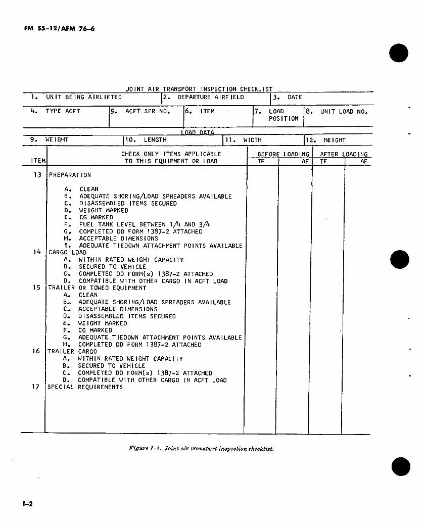
FM 55-12/AFM 76-6
JOINT AIR TRANSPORT INSPECTION CHECKLIST
1. UNIT BEING AIRLIFTED 2. DEPARTURE AIRFIELD 3. DATE
TYPE ACFT 5. ACFT SER NO. 6. ITEM 7. LOAD POSITION
8. UNIT LOAD NO.
LOAD DATA 9. WEIGHT 10. LENGTH 11. WIDTH 12. HEIGHT
ITEM CHECK ONLY ITEMS APPLICABLE
TO THIS EQUIPMENT OR LOAD BEFORE LOADING TF AF
AFTER LOADING TF AF
13 PREPARATION
lit
15
16
17
A. CLEAN B. ADEQUATE SHORING/LOAD SPREADERS AVAILABLE C. DISASSEMBLED ITEMS SECURED D. WEIGHT MARKED E. CG MARKED F^ FUEL TANK LEVEL BETWEEN ]/k AND 3/^ G. COMPLETED DD FORM 1387-2 ATTACHED H. ACCEPTABLE DIMENSIONS I. ADEQUATE TIEDOWN ATTACHMENT POINTS AVAILABLE
CARGO LOAD A. WITHIN RATED WEIGHT CAPACITY B* SECURED TO VEHICLE C* COMPLETED DD FORM(s) 1387-2 ATTACHED D. COMPATIBLE WITH OTHER CARGO IN ACFT LOAD
TRAILER OR TOWED EQUIPMENT A* CLEAN B^ ADEQUATE SHORING/LOAD SPREADERS AVAILABLE C^ ACCEPTABLE DIMENSIONS 0,. DISASSEMBLED ITEMS SECURED E* WEIGHT MARKED F^ CG MARKED G« ADEQUATE TIEDOWN ATTACHMENT POINTS AVAILABLE H. COMPLETED DD FORM 1387-2 ATTACHED
TRAILER CARGO A* WITHIN RATED WEIGHT CAPACITY B. SECURED TO VEHICLE C* COMPLETED DD FORM(s) 1387-2 ATTACHED D. COMPATIBLE WITH OTHER CARGO IN ACFT LOAD
SPECIAL REQUIREMENTS
Figure 1-1. Joint air transport inspection checklist.
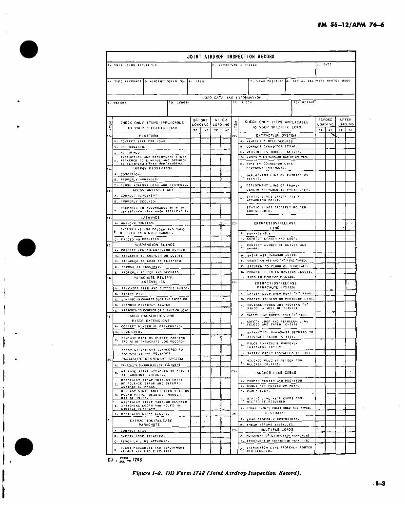
FM 55-12/AFM 76-6
JOINT AIRDROP INSPECTION RECORD
1. UNIT BEING A I RL I E TED 2- DEPARTURE AIRFIELD
A. TYPE AIRCRAFT J. AIRCRAFT SERIAL NO. 5- ITEM 7. LOAD POSITION 8- AERIAL DELIVERY SYSTEM USED
LOAD DATA TAG INFORMATION
9. WEIGHT 10 LENGTH II WIDTH 12. HEIGHT
CHECK ONLY ITEMS APPLICABLE
TO YOUR SPEC I F 1C LOAD
BEFORE LOAD ING
AFTER LOAD ING
CHECK ONLY ITEMS APPLICABLE
TO YOUR SPECIFIC LOAD
BEFORE LOADING
AFTER LOAD ING
CORRECT SIZE FOR LOAD.
NOT DAMAGED.
NOT BOWED-
EXTRACTJON AND DEPLOYMENT LINES ATTACHED TO LINKAGE ANO SECURED TO PLATFORM (When Applicable)
ENERGY DISSIPATOR
CONDIT I ON.
e. PROPERLY ARRANGED.
FLUSH AGAINST LOAD AND PLATFORM.
ACCOMPANYING LOAD
CORRECT PLACEMENT.
PROPERLY SECURED-
PREPARED IN ACCORDANCE WITH TM 38*250/AFM 71-4 WHEN APPLICABLE-
EXTRACTION SYSTEM
A. VEHICLE PINTLE SECURED
CORRECT CONNECTOR STRAP.
WEBBING 1$ THROUGH KNIVES-
D. SAFETY TIES THROUGH BAR OF KNIVES.
TYPE IV CONNECTOR LINK PROPERLY INSTALLED.
DEPLOYMENT LINE ON EXTRACTION CLEVIS.
DEPLOYMENT LINE OF PROPER
LENGTH ATTACHED TO PARACHUTES-
STATIC LINES SAFETY TIE AT ATTACH ING POINT.
STATIC LINES PROPERLY ROUTED AND SECURED.
UN I FORM TENSION.
EXCESS LASHING FOLDED AND TAPED OR TIED TO BINDER HANDLE.
PADDED AS REQUIRED.
SUSPENSION SLINGS
CORRECT LENGTH.LOOP,AND NUMBER.
ATTACHED TO COUPLER OR CLEVIS-
ATTACHED TO LOAD OR PLATFORM.
PADDED AS REQUIRED.
PROPERLY ROUTED AND SECURED ,
PARACHUTE RELEASE
ASSEMBLI ES
RELEASES TIED AND CUTTERS ARMED.
SAFETY PIN.
LINKAGE IN CORRECT SLOT AND SAFETlED.
SPINNER PROPERLY SEATED-
ATTACHED TO COUPLER OR CLEVIS ON LOAD,
CARGO PARACHUTES AND
RISER EXTENSIONS
CORRECT NUMBER OF PARACHUTES.
B. CLUSTERED.
COMPARE DATE ON CUTTER WARNING
TAG WITH PARACHUTE LOG RECORD-
P Ic E R EXTENSIONS CONNECTED TO
-^»ACHUTES AND RELEASES.
PARACHUTE RESTRAINT SYSTEM
A. PARACHUTE SECURED TO LOAD ( Sinfl / ej .
EXTRACTION/RELEASE
L INE
SERVICE ABLE.
B. CORRECT LENGTH AND LOOP.
CORRECT NUMBER OF KNIVES AND SHARP.
SHEAR WEB THROUGH KNIFE.
£. UNUSED KNIVES AND "v" RING TAPED.
SECURED TO FLOOR OF AIRCRAFT.
CONNECTED TO EXTRACTION CLEVIS.
TICO TO PROPCR RECESS-
EXTRACTION/RELEASE PARACHUTE SYSTEM
A. SAFETY LOOP OVER BENT "v" RING-
PROPER TENSION ON PENDULUM LINE.
RELEASE HOOKS ARE HOOKING "V" RINGS IN WELL OF SHACKLE.
SAFETY LINE THROUGH BENT 'V RING.
EXTRACTION PARACHUTE SECURED TO
AI BCR AFT FLOOR IC- 119).
PILOT PARACHUTE PROPERLY INSTALLED (C- 1 t9 I•
SAFETY CABLE INSTALLED IC*119>
RELEASE PLUG IN GLIDER TOW RELEASE (C- I 19)•
RELEASE STRAP ATTACHED TO CLEVIS AT PARACHUTE BRIDLES.
RESTRAINT STRAP THROUGH KNIFE c> OF RELEASE STRAP AND SECURED
AGAINST SLIPPAGE-
RELEASE STRAP KNIFE TIED WITH POUND COTTON WEBBING THROUGH BAR OF KNIFE-
RESTRAINT STRAP THROUGH CLUSTER
ATTACHING LOOPS AND HOLES IN STOWAGE PLATFOiRM.
ANCHOR LI NE CABLE
A. PROPER NUMBER ANO POSITION.
CABLE NOT FRAYED OR WORN.
CABLE TAUT.
STATIC LINE RETRIEVERS CON- NECTED IF REQUIRED.
CABLE CLAMPS POSITIONED AND TAPED.
F. RESTRAINT STRAP SECURED
EXTRACTION/RELEASE PARACHUTE
RESTRAINT
LOAD PROPERLY RESTRAINED.
SHEAR STRAPS INSTALLED.
CORRECT SIZE.
SAFETY LOOP ATTACHED.
C. PENDULUM LINE ATTACHED.
PILOT PARACHUTE AND DEPLOYMENT ’■ WEIGHT AVAILABLE (C-119).
MULT I PLE LOADS
PLACEMENT OF EXTRACTION PARACHUTE.
B. ATTACHMENT OF EXTRACTION PARACHUTE
EXTRACTION LINE PROPERLY ROUTED AND SECURED.
Figure I~2. DD Form 1748 (Joint Airdrop Inspection Record).
1-3
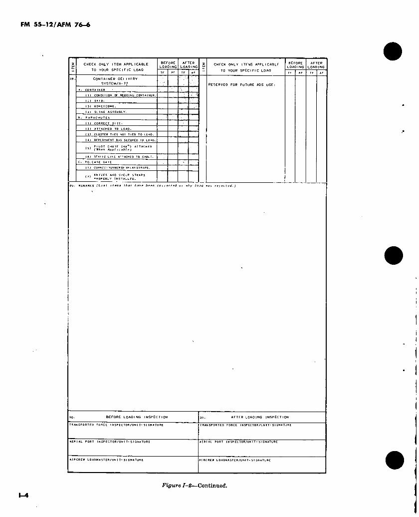
FM 55-12/AFM 76-6
CHECK ONLY ITEM APPLICABLE
TO YOUR SPECIFIC LOAD
BEFORE LOAOlNg
AFTER LOADING
CHECK ONLY ITEMS APPLICABLE
TO YOUR SPECIFIC LOAD
BEFORE LOADING
AFTER LOADING
CONTAINER DELIVERY SYSTEM/A.22 RESERVED FOR FUTURE ADS USE:
A. CON TA I N Eft
(1) CONDITION OF WEBBING CONTAINER,
131 HONEYCOMB.
(4) SLING ASSEMBLY-
PARACHUTES
( 1 ) CORRECT SIZE.
(2) ATTACHED TO LOAD.
( 3) CLUSTER TIES NOT TIED TO LOAD.
(4J DEPLOYMENT BAG SECURED TO LOAD.
PILOT CHUTE (66 I ATTACHED (Wh en App Iicable)
(6) STATIC LINE ATTACHED TO CABLE
RELEASE GATE
( I ) CORRECT NUMBER OF SHEAR STRAPS .
KNIVES AND SHEER STRAPS °ROPERLY INSTALLED.
2*. REMARKS (Li items that have been corrected or vhy load was rejected.)
BEFORE LOADING INSPECTION AFTER LOADING INSPECTION
TRANSPORTED FORCE 1NSPECTOR/UN I T-SIGNATURE TRANSPORTED FORCE IN SPEC TOR/UN IT-SIGNATURE
AERIAL PORT INSP ECTOR/UNI T-S IGNATURE AERIAL PORT INSP ECTOR/UN I T - SIGNATURE
AIRCREW LOADMASTER/UNIT-SIGNATURE AIRCREW LOADMASTER/UNIT- SI GNATURE
Figure 1-2—Continued.
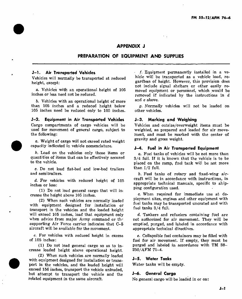
FM 55-12/AFM 76-4
APPENDIX J
PREPARATION OF EQUIPMENT AND SUPPLIES
J-l. Air Transported Vehicles Vehicles will normally be transported at reduced height, except:
a. Vehicles with an operational height of 105 inches or less need not be reduced.
b. Vehicles with an operational height of more than 105 inches and a reduced height below 105 inches need be reduced only to 105 inches.
J-2. Equipment in Air Transported Vehicles Cargo compartments of cargo vehicles will be used for movement of general cargo, subject to the following:
a. Weight of cargo will not exceed rated weight capacity indicated in vehicle nomenclature.
b. Load on the vehicles only those items or quantities of items that can be effectively secured to the vehicle.
c. Do not load flat-bed and low-bed trailers and semitrailers.
d. For vehicles with reduced height of 105 inches or less:
(1) Do not load general cargo that will in- crease the height above 105 inches.
(2) When such vehicles are normally loaded with equipment designed for installation or transport in the vehicles and the loaded height will exceed 105 inches, load that equipment only when advice from major Army command or thr supporting Air Force carrier indicates that C-5 aircraft will be available for the movement.
e. For vehicles with reduced height in excess of 105 inches:
(1) Do not load general cargo so as to in- crease loaded height above operational height.
(2) When such vehicles are normally loaded with equipment designed for installation or trans- port in the vehicles, and the loaded height will exceed 156 inches, transport the vehicle unloaded, but attempt to transport the vehicle and the related equipment in the same aircraft.
f. Equipment permanently installed in a ve- hicle will be transported as a vehicle load, re- gardless of height. However, this provision does not include signal shelters or other easily re- moved equipment or personnel, which would be removed if indicated by the instructions in d and e above.
g. Normally vehicles will not be loaded on other vehicles.
J-3. Marking and Weighing Vehicles and outsize/overweight items must be weighted, as prepared and loaded for air move- ment, and must be marked with the center of gravity and gross weight.
J-4. Fuel in Air Transported Equipment a. Fuel tanks of vehicles will be not more than
3/4 full. If it is known that the vehicle is to be placed on the ramp, fuel tank will be not more than 1/2 full.
b. Fuel tanks of rotary and fixed-wing air- craft will be in accordance with instructions, in appropriate technical manuals, specific to ship- ping configuration used.
c. When required for immediate use at de- ployment sites, engines and other equipment with fuel tanks may be transported uncrated and with fuel tanks 3/4 full.
d. Tankers and refuelers containing fuel are not authorized for air movement. They will be emptied, purged, and labeled in accordance with appropriate technical directives.
e. Collapsible fuel containers may be filled with fuel for air movement. If empty, they must be purged and labeled in accordance with TM 38- 250/AFM 71-4.
J-5. Water Tanks Water tanks will be empty.
J-6. General Cargo No general cargo will be loaded in or on:
J-Î

FM 55-12/AFM 76-6
a. 1/4 ton trucks.
b. 1/2 ton utility vehicles.
c. Tracked vehicles, except "carrier, cargo, amphibious,” and “carrier, cargo, full-tracked.”
d. Supplies and equipment not loaded into vehicle cargo compartments will be unitized on 40- by 48-inch pallets, or packed in CONEX in- serts or other suitable containers. Do not exceed 1,000 pounds per insert nor 2,000 pounds per pal- let. Pallets and inserts will be identified on air- craft loading tables.
J—7. CONEX Containers Use of CONEX must be approved by major Army command. Request for approval must show that CONEX provides a distinct advantage or is an operational necessity. Approval will be based
on an evaluation of the request and availability of MHE at origin and destination airfields.
J-8. Dangerous Materials TM 38-250/AFM 71-4, provides instructions for preparing explosives and other dangerous ma- terials for movement by military aircraft. These instructions are intended to assure that such ma- terials are properly prepared for transportation.
а. For the purpose of complying with para- graphs 1-3« and l-3o, TM 38-250/AFM 71-4, “participating troops” are not considered “pas- sengers.”
б. When applying the configured type loads contained in table 1-1, TM 38-250/AFM 71-4, one or more of the items may be omitted but in no instance will items not previously approved as a part of the type load be added.
J—2
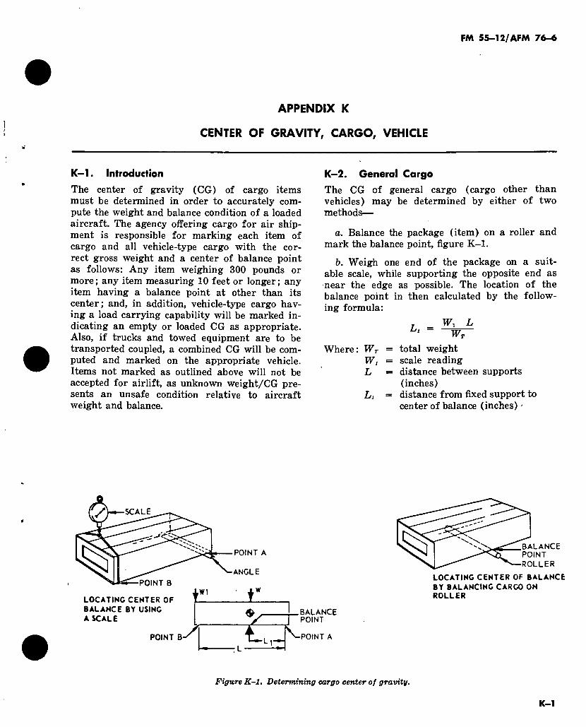
FM 55-12/AFM 76-6
APPENDIX K
CENTER OF GRAVITY, CARGO, VEHICLE
K-1. Introduction
The center of gravity (CG) of cargo items must be determined in order to accurately com- pute the weight and balance condition of a loaded aircraft. The agency offering cargo for air ship- ment is responsible for marking each item of cargo and all vehicle-type cargo with the cor- rect gross weight and a center of balance point as follows: Any item weighing 300 pounds or more ; any item measuring 10 feet or longer ; any item having a balance point at other than its center; and, in addition, vehicle-type cargo hav- ing a load carrying capability will be marked in- dicating an empty or loaded CG as appropriate. Also, if trucks and towed equipment are to be transported coupled, a combined CG will be com- puted and marked on the appropriate vehicle. Items not marked as outlined above will not be accepted for airlift, as unknown weight/CG pre- sents an unsafe condition relative to aircraft weight and balance.
K-2. General Cargo
The CG of general cargo (cargo other than vehicles) may be determined by either of two methods—
a. Balance the package (item) on a roller and mark the balance point, figure K-1.
b. Weigh one end of the package on a suit- able scale, while supporting the opposite end as near the edge as possible. The location of the balance point in then calculated by the follow- ing formula:
Where: WT
W, L
Li
T _ Wi L Ll W7~
total weight scale reading distance between supports (inches) distance from fixed support to center of balance (inches) -
SCALE
POINT A
ANGLE
POINT B W1
LOCATING CENTER OP
BALANCE BY USING A SCALE
POINT B-
.BALANCE POINT
-POINT A
BALANCE POINT ROLLER
LOCATING CENTER OF BALANCE
BY BALANCING CARGO ON ROLLER
Figure K-1. Determining cargo center of gravity.
K-1
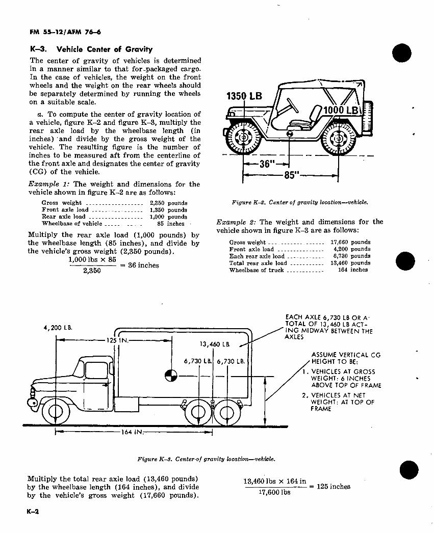
FM 55—12/AFM 76-6
K—3. Vehicle Center of Gravity The center of gravity of vehicles is determined in a manner similar to that for-packaged cargo. In the case of vehicles, the weight on the front wheels and the weight on the rear wheels should be separately determined by running the wheels on a suitable scale.
a. To compute the center of gravity location of a vehicle, figure K-2 and figure K-3, multiply the rear axle load by the wheelbase length (in inches) and divide by the gross weight of the vehicle. The resulting figure is the number of inches to be measured aft from the centerline of the front axle and designates the center of gravity (CG) of the vehicle.
Example 1: The weight and dimensions for the vehicle shown in figure K-2 are as follows:
Gross weight 2,350 pounds Front axle load 1,350 pounds Rear axle load 1,000 pounds Wheelbase of vehicle 85 inches ■
Multiply the rear axle load (1,000 pounds) by the wheelbase length (85 inches), and divide by the vehicle’s gross weight (2,350 pounds).
1,000 lbs x 85 = 36 inches
2,350
1350 LB \A 1000 LB\
<5* 9
36 85"
Figure K-2. Center of gravity location—vehicle.
Example 2: The weight and dimensions for the vehicle shown in figure K-3 are as follows:
Gross weight 17,660 pounds Front axle load 4,200 pounds Each rear axle load 6,730 pounds Total rear axle load 13,460 pounds Wheelbase of truck 164 inches
4,200 LB.
125 IN. 13,460 LB
6,730 LB. 6,730 LB.
O Q O 164 IN:
MALE 6,/JU Lb UR A TOTAL OF 13,460 LB ACT- ING MIDWAY BETWEEN THE AXLES
ASSUME VERTICAL CG HEIGHT TO BE:
1. VEHICLES AT GROSS WEIGHT: 6 INCHES ABOVE TOP OF FRAME
2. VEHICLES AT NET WEIGHT: AT TOP OF FRAME
Figure K-3. Center-of gravity location—vehicle.
Multiply the total rear axle load (13,460 pounds) 13 460 lbs x 164 in by the wheelbase length (164 inches), and divide — — = 125 inches by the vehicle’s gross weight (17,660 pounds). 17,600lbs
K-2
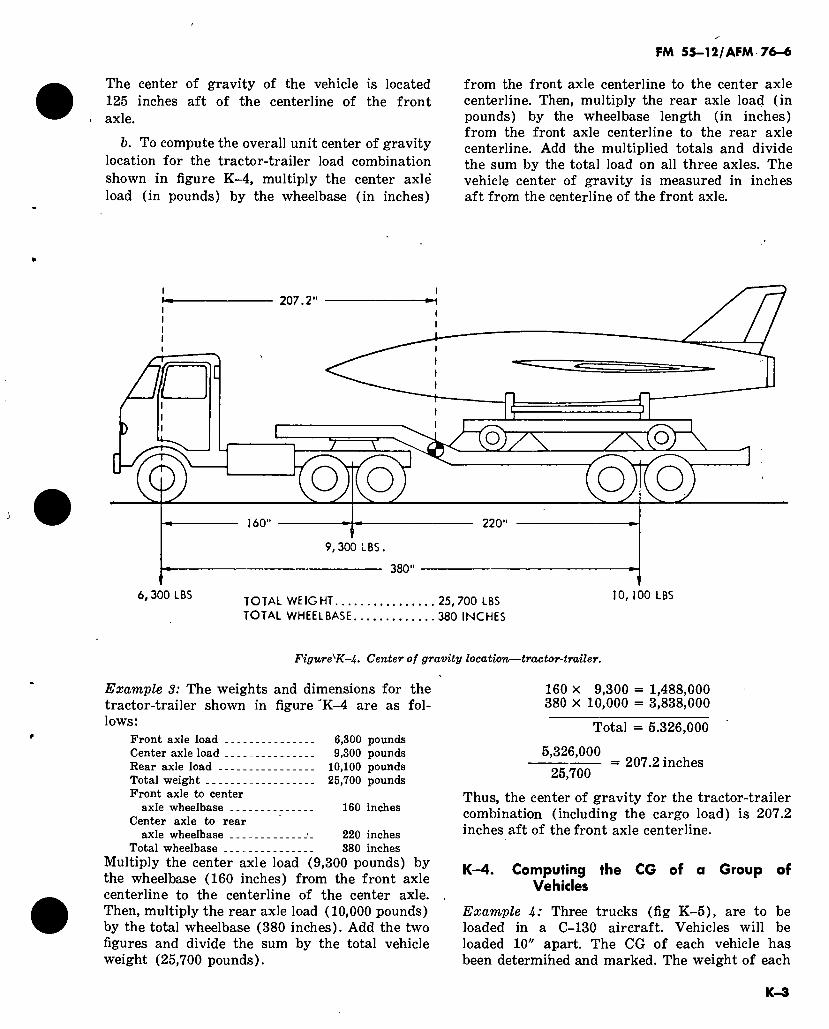
FM 55-12/AFM 76-6
The center of gravity of the vehicle is located 125 inches aft of the centerline of the front
< axle.
b. To compute the overall unit center of gravity location for the tractor-trailer load combination shown in figure K-4, multiply the center axle’ load (in pounds) by the wheelbase (in inches)
from the front axle centerline to the center axle centerline. Then, multiply the rear axle load (in pounds) by the wheelbase length (in inches) from the front axle centerline to the rear axle centerline. Add the multiplied totals and divide the sum by the total load on all three axles. The vehicle center of gravity is measured in inches aft from the centerline of the front axle.
207.2"
O o zr—\
o o 160" 220
6,300 LBS
9,300 LBS.
- 380"
TOTAL WEIGHT 25,700 LBS TOTAL WHEELBASE 380 INCHES
10,100 LBS
Figure^K-i. Center of gravity location—tractor-trailer.
Example 3: The weights and dimensions for the tractor-trailer shown in figure ’K-4 are as fol- lows:
Front axle load 6,300 pounds Center axle load 9,300 pounds Rear axle load 10,100 pounds Total weight 25,700 pounds Front axle to center
axle wheelbase 160 inches Center axle to rear
axle wheelbase 220 inches Total wheelbase 380 inches
Multiply the center axle load (9,300 pounds) by the wheelbase (160 inches) from the front axle centerline to the centerline of the center axle. Then, multiply the rear axle load (10,000 pounds) by the total wheelbase (380 inches). Add the two figures and divide the sum by the total vehicle weight (25,700 pounds).
160 X 9,300 = 1,488,000 380 X 10,000 = 3,838,000
Total = 5.326,000
5,326,000
25,700 207.2 inches
Thus, the center of gravity for the tractor-trailer combination (including the cargo load) is 207.2 inches aft of the front axle centerline.
K-4. Computing the CG of a Group of Vehicles
Example U: Three trucks (fig K-5), are to be loaded in a C-130 aircraft. Vehicles will be loaded 10" apart. The CG of each vehicle has been determined and marked. The weight of each
K-3
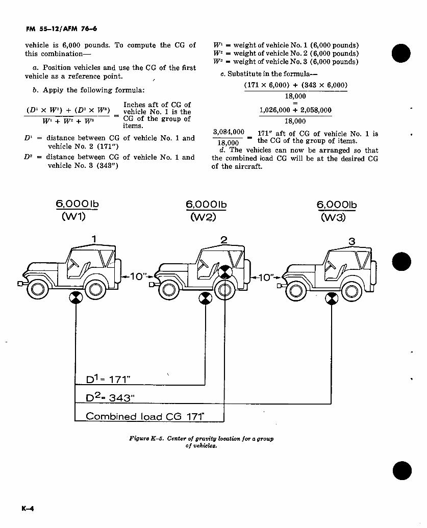
FM 55-12/AFM 76-6
vehicle is 6,000 pounds. To compute the CG of this combination—
a. Position vehicles and use the CG of the first vehicle as a reference point.
b. Apply the following formula:
(D1 x W2) + (D2 x W3)
W1 + W2 + W3
Inches aft of CG of _ vehicle No. 1 is the “ CG of the group of
items.
D1 = distance between CG of vehicle No. 1 and vehicle No. 2 (171")
D2 = distance between CG of vehicle No. 1 and vehicle No. 3 (343")
Wl = weight of vehicle No. 1 (6,000 pounds) W2 = weight of vehicle No. 2 (6,000 pounds) W3 = weight of vehicle No. 3 (6,000 pounds)
c. Substitute in the formula—
(171 x 6,000) + (343 x 6,000)
18,000
1,026,000 + 2,058,000
18,000
3,084,000 ^ 171" aft 0f QQ 0f vehicle No. 1 is
18,000 2rouP °f items. d. The vehicles can now be arranged so that
the combined load CG will be at the desired CG of the aircraft.
6,0001b (Wl)
6,0001b (W2)
6,0001b (W3)
-10”-
/
D1= 171”
D2= 343”
Combined load CG 17T
-10”-
ÇK
&
Figure K-S. Center of gravity location for a group of vehicles.
K—4
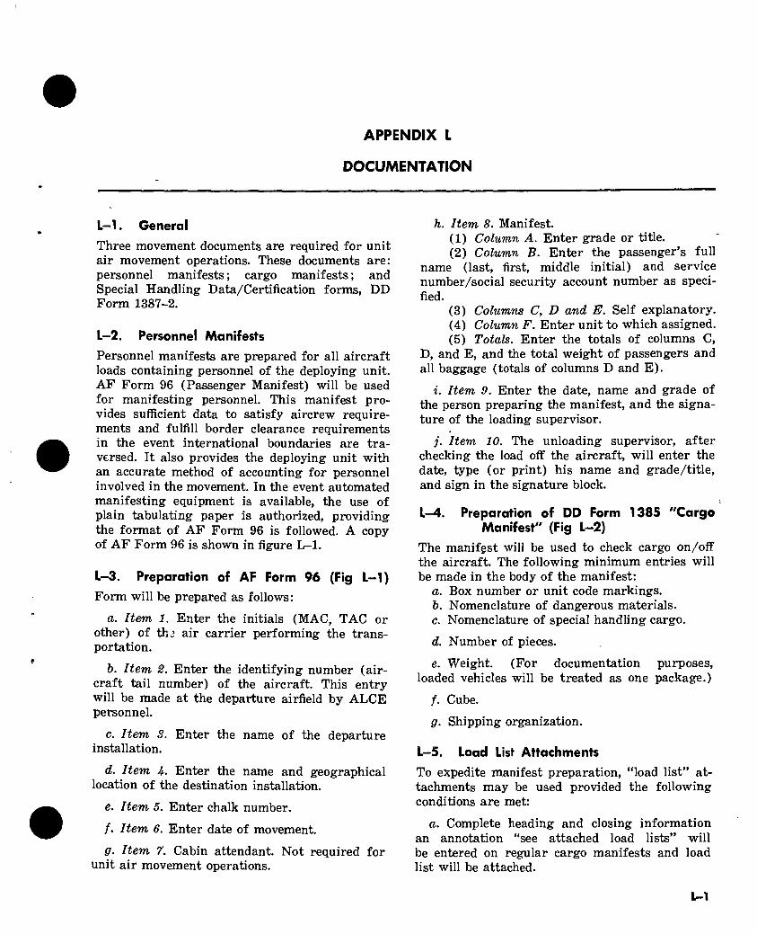
APPENDIX L
DOCUMENTATION
L-l. General
Three movement documents are required for unit air movement operations. These documents are: personnel manifests ; cargo manifests ; and Special Handling Data/Certification forms, DD Form 1387-2.
L—2. Personnel Manifests
Personnel manifests are prepared for all aircraft loads containing personnel of the deploying unit. AF Form 96 (Passenger Manifest) will be used for manifesting personnel. This manifest pro- vides sufficient data to satisfy aircrew require- ments and fulfill border clearance requirements in the event international boundaries are tra- versed. It also provides the deploying unit with an accurate method of accounting for personnel involved in the movement. In the event automated manifesting equipment is available, the use of plain tabulating paper is authorized, providing the format of AF Form 96 is followed. A copy of AF Form 96 is shown in figure L-l.
L-3. Preparation of AF Form 96 (Fig L-1) Form will be prepared as follows:
a. Item 1. Enter the initials (MAC, TAC or other) of thj air carrier performing the trans- portation.
5. Item 2. Enter the identifying number (air- craft tail number) of the aircraft. This entry will be made at the departure airfield by ALCE personnel.
c. Item 3. Enter the name of the departure installation.
d. Item U- Enter the name and geographical location of the destination installation.
e. Item 5. Enter chalk number.
/. Item 6. Enter date of movement.
fir. Item 7. Cabin attendant. Not required for unit air movement operations.
h. Item 8. Manifest. (1) Column A. Enter grade or title. (2) Column B. Enter the passenger’s full
name (last, first, middle initial) and service number/social security account number as speci- fied.
(3) Columns C, D and E. Self explanatory. (4) Column F. Enter unit to which assigned. (5) Totals. Enter the totals of columns C,
D, and E, and the total weight of passengers and all baggage (totals of columns D and E).
i. Item 9. Enter the date, name and grade of the person preparing the manifest, and the signa- ture of the loading supervisor.
j. Item 10. The unloading supervisor, after checking the load off the aircraft, will enter the date, type (or print) his name and grade/title, and sign in the signature block.
L—4. Preparation of DD Form 1385 "Cargo Manifest" (Fig L-2)
The manifest will be used to check cargo on/off the aircraft. The following minimum entries will be made in the body of the manifest:
a. Box number or unit code markings. b. Nomenclature of dangerous materials. c. Nomenclature of special handling cargo.
d. Number of pieces.
e. Weight. (For documentation purposes, loaded vehicles will be treated as one package.)
f. Cube.
fir. Shipping organization.
L-5. Load List Attachments
To expedite manifest preparation, “load list” at- tachments may be used provided the following conditions are met:
a. Complete heading and closing information an annotation “see attached load lists” will be entered on regular cargo manifests and load list will be attached.
L-l
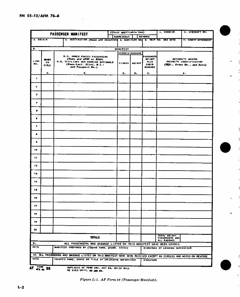
FM 55-12/AFM 76-6
PASSENGER MANIFEST (Check tppiicmble boa)
NONREVENUE n
I. CARRIER 2. AIRCRAFT NO*
3. ORIGIN 4. DESTINATION (Nsmo mttd location^ s. MANTFESTT Na 6. TRIP NO. AND DATE yrrmirr^mm
e. MANIFEST
LINE NO.
GRADE
OR
TITLE
U.S. ARMED FORCES PASSENGERS (Nomo ond AFSN or SSAN)
• S. CIVILIANS AND FOREIGN NATIONALS
(Norno-Loot, Pirot, N.I.- •od Poooport No,)
CHECKED BAGGAGE
0.
PASSENGER WEIGHT
PLUS CABIN
BAGGAGE
AUTHORITY AND/OR PRIORITY IDENTIFICATION
(BQS, t Or dor No,, and Doto).
P.
12
14
IS
IB
TOTALS TOTAL WEIGHT I PASSENGERS ANDI ALL BAGGAGE I
DATE
ALL PASSENGERS AND BAGGAGE LISTED ON THIS MANIFEST HAVE BEEN LOADED.
MANIFEST PREPARED BY (Typed nomo, grado, titio) SIGNATURE OF LOADING SUPERVISOR
IQ. ALL PASSENGERS AND BAGGAGE LISTED ON THIS MANIFEST HAVE BEEN RECEIVED EXCEPT AS CIRCLED AND NOTED ON REVERSE.
0ATE I PRINTED NAME« GRADE OR TITLE OF UNLOADING SUPERVISOR I SIGNATURE
AF ¿n 96 REPLACES AF FORM itb. OCT 63, WHICH WILL ■E USED UNTIL «0 JBN 6».
Figure L-l. AF Form 96 (Passenger Manifest).
L-2
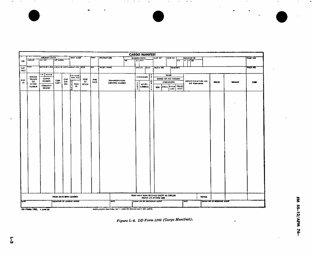
CARGO MANIFEST AIIC•API D*TA
VC AOOll MISSION PAT* MANIMST 10
sut uct
ÙATC MII.CO OVACC OOCUUCMTNO STATUS SUST TIUCK NO •(MAtlS MÄIWÖ
d I W*KK
viwat * TCAlKK
Ol OlTNI
NUMB(t
04 TNI
NU Mitt COM <ODt
coMMOrr Otscii*
CAI CO ttc
CONStONCi
T:NS
fT
ron Of
DlSCM
TYft PACK
TtANSAOITATlON
CONTIOl NUMKt ACTVIT
AODttSS
LOT NO /NOMCN
(AA PROJ * TOW TtANS LOC ACCT
IDINTIFIC ATIOW NO.
OM «KMAKKS
nua HA VC HCN lOAMOl (TIMS HArl IlfN KCCIVCO IICOT AS CtKUD
NOTID ON IfVCtSf SIOC
MNA'ült Of U*«OAOMC AGCNf ~ yct^um OUKWNO AOOtf ftlONAlUtl 0* LOADING AGMl
00 FOAM IMS, I A PH M NtPUACK* COITtON OW » APR •» «MICH MAT •« UDCO.
Figure L-2. DD Form 1385 (Cargo Manifest).
I
FM
55-1
2/A
FM 76-
FM 55-12/AFM 76-6
b. Load lists for cargo will show shipping organization, box number or unit code markings, nomenclature of all dangerous or other special handling type cargo, number of pieces, weight and cubage of each shipment.
c. Load list attachment must be prepared on standard or legal size paper. Load lists must be prepared in the same number of copies as the cover manifests so each manifest will have an attached load list.
L-6. Preparation of DD Form 1387—2, Special Handling Data/Certification (Fig L—3)
DD Form 1387-2 is required for all dangerous cargo airlifted. Identification of dangerous cargo, as well as preparation and handling instructions, is contained in TM 38-250/AFM 71-^4. The form will be completed in accordance with instruc- tions contained in TM 38-250/AFM 71-4. DD Form 1387-2 prepared as indicated above will be affixed to each self-propelled vehicle. These forms, in addition to forms prepared for other danger- ous cargo, will be attached to each required copy of the cargo manifest. If other dangerous ma- terials are carried as cargo on self-propelled vehicles, a DD Form 1387-2 will be prepared for that hazardous cargo and affixed to each vehicle transporting such cargo as required by TM 38- 250/AFM 71-4.
1—7. Manifest Distribution
A minimum of 7 copies of each personnel and cargo manifest are normally required for unit air movements. An additional copy may be re- quired for each intermediate stop between sta- tions of origin and destination. Copies will be distributed as follows:
a. Parent station file 1 copy
b. Planeload commander (deploying unit) 1 copy
c. Departure airfield control group file (DACG) 1 copy
d. Airlift control element file (ALCE-departure airfield) -. 1 copy
e. Aircrew (senior aircraft loadmaster) 1 copy
/. Airlift control element file (ALCE-arrival airfield) 1 copy
g. Arrival airfield control group - (AACG) 1 copy
h. En route stations 1 copy/station Deviations from the above requirements will be established during the joint planning confer- ence.
L—4
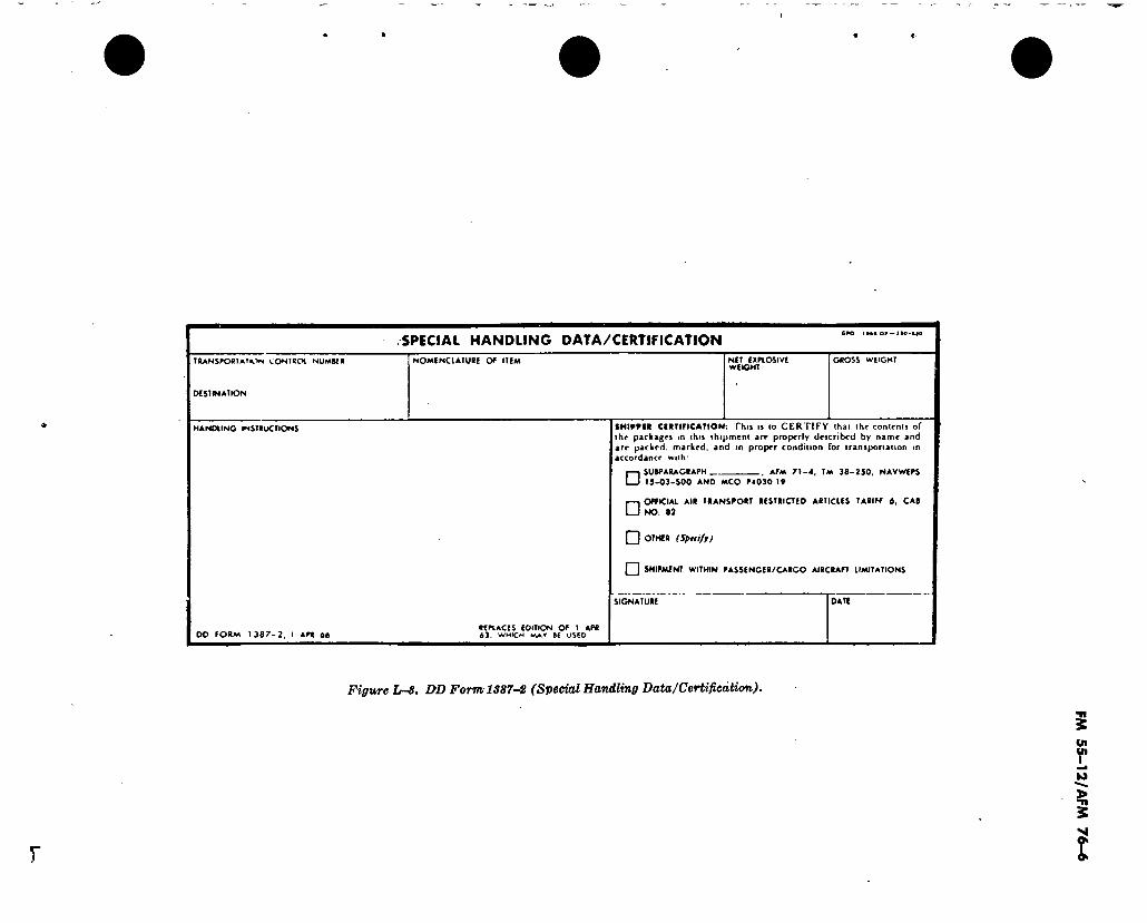
.SPECIAL HANDLING DATA/CERTIFICATION 6PO !••• OJ —210-#}0
TRANSPO0îATK'tN CONfRCH NUMM«
DCSTMATION
NOMINCLATURE OP ITEM NET EXPLOSIVE WEIGHT
GROSS WEIGHT
HANDLING INSTRUCTIONS
00 PORM 1367-2. I APR 6ô REPLACES EDITION OP I APR 63. WHICH MAY 66 USED
SHIPPER CERTIFICATION: This is to CERTIFY lhai the contents of the packages in this shipment are properly described by name and are packed, marked, and in proper condition for transportation m accordance with
□ □
SURPARAGRAPH AFM 71-4, TM 36-250, NAVWEPS 15-03-500 AND MCO P4030 19
OFFICIAI AIR TRANSPORT RESTRICTED ARTICLES TARIFF 6. CAB NO. 82
□ OTHER (Specify)
I I SHIPMENT WITHIN PASSENGER/CARGO AIRCRAFT UMITATIONS
SIGNATURE DATE
Figure L-8. DD Form 1387-8 (Special Handling Data/Certificàtion).
y
FM
55-1
2/A
FM 7
6-6

i
)
FM 55-12/AFM 76-6
APPENDIX M
DUTIES OF PLANELOAD COMMANDER
M-l. Planeload Commander A planeload commander is designated for each aircraft. Such action is necessary to insure the proper control and movement of troop loads.
M-2. Duties The planeload commander will:
a. Be present at the passenger briefing for his flight.
b. Assume control of all passengers listed for movement on his flight and insure that all are informed of formations, expected departure, and reporting time.
c. Be readily available to the Unit Movement Officer (UMO) at all times. Personnel will not be dismissed without the approval of the UMO.
d. Check roll prior to reporting for loading to insure everyone is present for the flight. Report no-show passengers to the UMO so that standby passengers may be sleeted to complete the load.
Note. Coordinate time for roll check with UMO.
e. Insure that each man has placed his baggage on the proper vehicle for transport to the aircraft.
f. Check the loading of passengers to insure that each individual appearing on the mani- fest is loaded aboard the aircraft.
g. Maintain planeload commander’s itinerary (fig M-l).
h. Brief all passengers on maintaining secur- ity of their personal belongings and insure that any passenger removed from a flight has his baggage removed with him.
i. Collect all clips and ammunition and keep them in his custody during flight, reissuing same as required en route to or at destination.
j. Maintain in-flight discipline of all passen- gers and insure their compliance with smoking restructions.
k. If in-flight rations are issued, control their issue to troops.
l. Assist in maintaining a clean and safe con- dition in the aircraft.
m. At en route stations,> determine ground time from the loadmaster and take positive ac- tion to insure that all passengers are present to meet flight departure times. Know which pas- sengers will be offloaded should it become nec- essary to take such action at an en route station. In the event passengers are offloaded, or deploy- ing personnel are added to the manifest at an intermediate stop, notify the departure airfield by operational immediate message (fig M-2), in- cluding the name, rank, social security number and organization of personnel affected, along with the reason for the change, and type of air- craft and tail number. The final destination base will be included as an information addressee un- less the destination is classified.
n. Brief passengers on load restrictions and conduct at en route stops. Some stations may at times restrict passengers to the base area be- cause of local conditions. Pertinent facts on local conditions can be determined from the traffic representative meeting the aircraft.
o. In the case of weather diversion into off- route bases, assist the aircraft commander in getting billeting and food for the aircraft pas- sengers, if such is required.
p. Upon arrival at destination, maintain an or- derly dispatch of the passengers and determine whether or not they are needed to assist with the offloading of baggage and/or cargo.
q. During en route servicing stops, if neces- sary, designate a guard for personal effects or material that must remain in the cabin of the aircraft. If required for this type of security, utilize two men to perform guard duty on an alternate basis.. If en route military bases do not arrange to provide hot meals for the security guards, then the base should be requested to provide acceptable security. Arrange for security coverage through base facilities when unusually long delays are encountered.
M-l
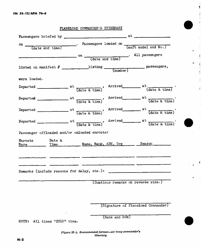
FM 55-12/AFM 76-«
PIAMELOAD COMMANDER'S ITINERARY
Passengers briefed by
on (date and time)
were loaded.
Departed
Departed
Departed
Departed
. Passengers loaded on
on
listed on manifest #
(date and time)
listing
(acft model and No.)
. All passengers
(number )
at , Arrived_ (date & time)
at
at
at
(date & time) , Arrived^
(date & time) , Arrived_
(date & time)
Passenger offloaded and/or onloaded enroute:
, Arrived_
Biroute Base
Date & Time Name, Rank, ASM, Org
passengers.
at (date & time)
at
at
at
(date & time)
(date & time)
(date & time)
Reason
Remarks (include reasons for delay, etc.):
(Continue remarks on reverse side.)
NOTE: All times "ZULU" time.
(Signature of Planeload Commander)
(Rank and SSN)
Figure M-l. Recommended format—air troop commander9s itinerary.
M-2
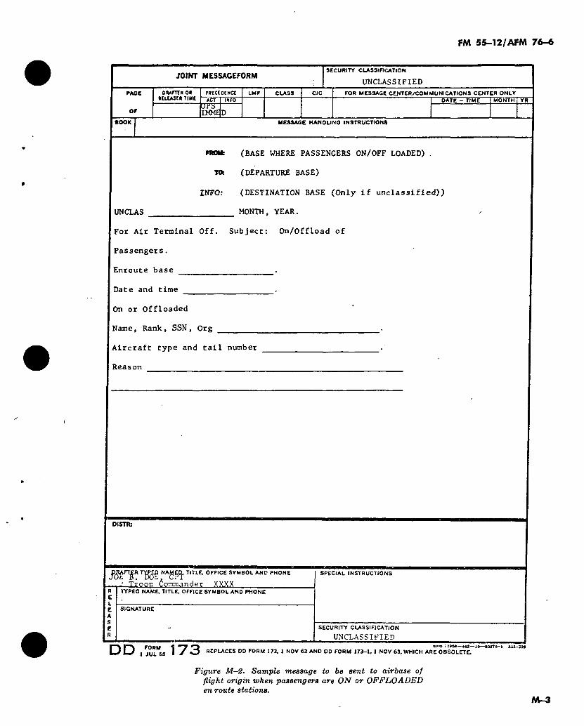
3oni(
A>
mr"
m:o
FM 55-12/AFM 76-6
JOINT MESSAGEFORM SECURITY CLASSIFICATION
UNCLASSIFIED
RAGE
or
ftCLEASER TIME
JFS IMME
FOR MESSAGE CEffTER/COMMUNICATIONS CENTER ONLY DATE - TIME MONTH YR
BOOK MESSAGE HANOUNO INSTRUCTIONS
TO:
INFO:
UN CL AS
(BASE WHERE PASSENGERS ON/OFF LOADED) .
(DEPARTURE BASE)
(DESTINATION BASE (Only if unclassified))
MONTH, YEAR.
For Air Terminal Off. Subject: On/Offload of
Passengers.
Enroute base .
Date and time .
On or Offloaded
Name, Rank, SSN, Org
Aircraft type and tail number
Reason
DISTTb
JggFlgR TIT1-E- OFFICE SYMBOL ANO PHONE
Troop ¿omaander XMXX TYPED NAME. TITLE, OFFICE SYMBOL AND PHONE
SIGNATURE
SPECIAL INSTRUCTIONS
SECURITY CLASSIFICATION
UNCLASSIFIED
DD FORM < a*o : iws—«a—10—SMTO-i uo-aoo
1 J U L 68 I ^ O REPLACES DD FORM 173, 1 NOV 63 AND OD FORM 173-1, 1 NOV 63, WHICH ARE OBSOLETE.
Figure M-2. Sample message to be sent to airbase of flight origin when passengers are ON or OFFLOADED en route stations.
M—3

i
FM 55-12/AFM 76-6
APPENDIX N
DEPARTURE AIRFIELD OPERATIONS
Figure N-l illustrates fixed areas of responsibilities for departure airfield operations only. Functional responsibilities will overlap.
N-l
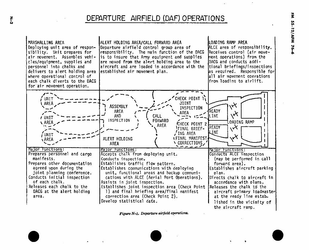
N-2
DEPARTURE AIRFIELD (DAF) OPERATIONS
MARSHALLING AREA Deploying unit area of respon- sibility. Unit prepares for air movement. Assembles vehi- cles/equipment, supplies and personnel into chalks and delivers to alert holding area where operational control of each chalk diverts to the DAC6 for air movement operation.
/—' / UNIT - \ AREA —
l UNIT - \ AREA ^ ^
I ~
f N / UNIT ^ ' \AREA ^
Major l-unct1onsi Prepares personnel and cargo
manifests. Prepares other documentation
agreed upon during the joint planning conference.
Conducts initial inspection of each chalk.
Releases each chalk to the DACG at the alert holding area.
ALERT HOLDING AREA/CALL FORWARD AREA Departure airfield control group area of responsibility. The main function of the DACG is to insure that Army equipment and supplies are moved from the alert holding area to the aircraft and are loaded in accordance with the established air movement plan.
LOADING RAMP AREA ALCE area of responsibility. Receives control (air move- ment operations) from the DACG and conducts addi- tional brief!ngs/insoections as required. Responsible for all air movement operations from loading to airlift.
— ✓
ASSEMBLY AREA AND
INSPECTION
ALERT HOLDING AREA
t \ \
I y
\ CALL FORWARD .AREA
%
„'CHECK POINT 1* ^ JOINT ' \ INSPECTION
s AREA- ^ W 1 - —
'CHECK POINT 2 FINAL BRIEF-
1
/ING AREA lFINAL MANIFEST v CORRECTIONS.'
N. — S'
EADY LINE
OADING RAMP
X READY NE
X
Major hunctions: chalk Accepts chalk from deploying unit.
Conducts inspection. Establishes traffic flow pattern. Establishes communications with deploying
unit, functional areas and backup communi- cations with ALCE (Aerial Port Operations).
Assists in joint inspection. Establishes joint inspection area (Check Point
1) and final briefing area/final manifest correction area (Check Point 2).
Develop statistical data.
Major l-unctions: Conducts ALCE inspection
(may be performed in call forward area).
Establishes aircraft parking plan.
Directs chalk to aircraft in accordance with plans.
Releases the chalk to' the aircraft primary loadmaster at the ready line estab-
lished in the vicinity of
the aircraft ramp.
Figure N-l. Departure airfield operations.
FM
55
—1
2/A
FM 7
6-6
FM 55-12/AFM 76-6
APPENDIX O
ARRIVAL AIRFIELD OPERATIONS
Figure 0-1 illustrates fixed areas of responsibilities for arrival airfield operations only. Functional re- sponsibilities will overlap.
0-1
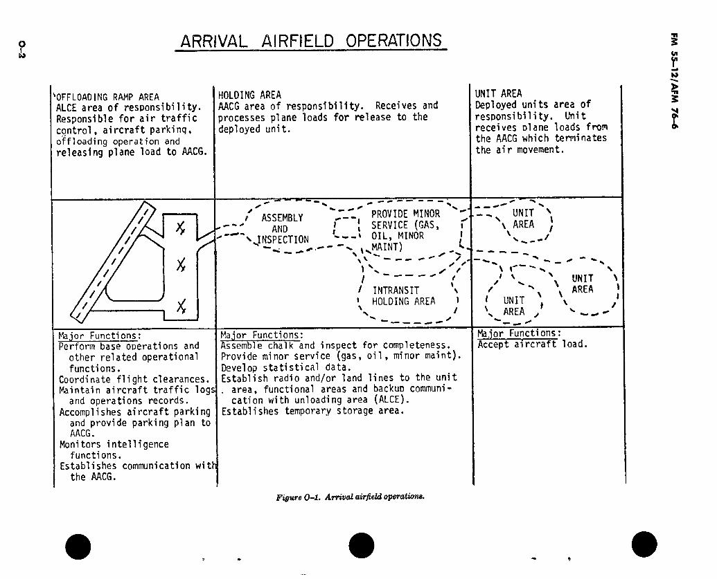
0-2
ARRIVAL AIRFIELD OPERATIONS
OFFLOADING RAMP AREA ALCE area of responsibility. Responsible for air traffic control, aircraft parking, offloading operation and
releasing plane load to AACG.
HOLDING AREA AACG area of responsibility. Receives and processes plane loads for release to the deployed unit.
UNIT AREA Deployed units area of responsibility. Unit receives olane loads from the AACG which terminates the air movement.
/ ASSEMBLY AND
'^INSPECTION
/ PROVIDE MINOR ^ i
X
SERVICE (GAS, -i OIL, MINOR
s. .MAINT) v ' ^ _ -
^ UNIT \ AREA J
v " y
I ' / INTRANSIT >
» HOLDING AREA » \ /
\ r i \ \ UNIT
x \ AREA ' UNIT ' \ . \ AREA / v ^ ^
Major Functions: Perform base operations and
other related operational functions.
Coordinate flight clearances. Maintain aircraft traffic logs
and operations records. Accomplishes aircraft parking
and provide parking plan to AACG.
Monitors intelligence functions.
Establishes communication with the AACG.
Major Functions: Assemblff chalk and inspect for completeness. Provide minor service (gas, oil, minor maint). Develop statistical data. Establish radio and/or land lines to the unit . area, functional areas and backup communi-
cation with unloading area (ALCE). Establishes temporary storage area.
Major Functions: Accept aircraft load.
Figure 0-1. Arrival airfield operations.
FM 5
5-1
2/A
FM 7
6-6

FM 55-12/AFM 76-6
APPENDIX P
MARSHALING CHECKLIST
P-1. Unit Movement Center
a. Communications to units operational.
b. DACG communications operational.
c. Necessary augmenting transportation coordinated. t
d. Planeload assembly point organized.
e. Planeload assembly point schedule issued.
/. Planeload assembly point guides briefed and provided with necessary signs, insignia.
g. Strip maps and route maps desseminated to drivers and troop/planeload commanders.
h. Guides to departure airfield coordinated.
i. Manifests prepared and one copy of each provided to Unit Movement Center.
P—2. Unit Commanders
а. Schedule received for movement to planeload assembly point and to departure airfield.
б. Personnel and vehicle loads completed.
c. Planeload assembly point guides dispatched.
d. Loading teams dispatched.
e. Drivers and troop/planeload commanders understand ac- tions and route to airfield.
f. Personnel briefed including : (1) Situation and mission. (2) Movement plan. (3) Assembly plan. (4) Operational plan. (5) Convoy discipline. (6) Loading procedures. (7) Aircraft safety and assembly procedures. (8) Transloading procedures (if applicable).
g. Manifests prepared.
h. Each vehicle marked with CG, weight, and chalk/mission number.
i. Individual helmets marked with chalk/mission number.
P-1

y
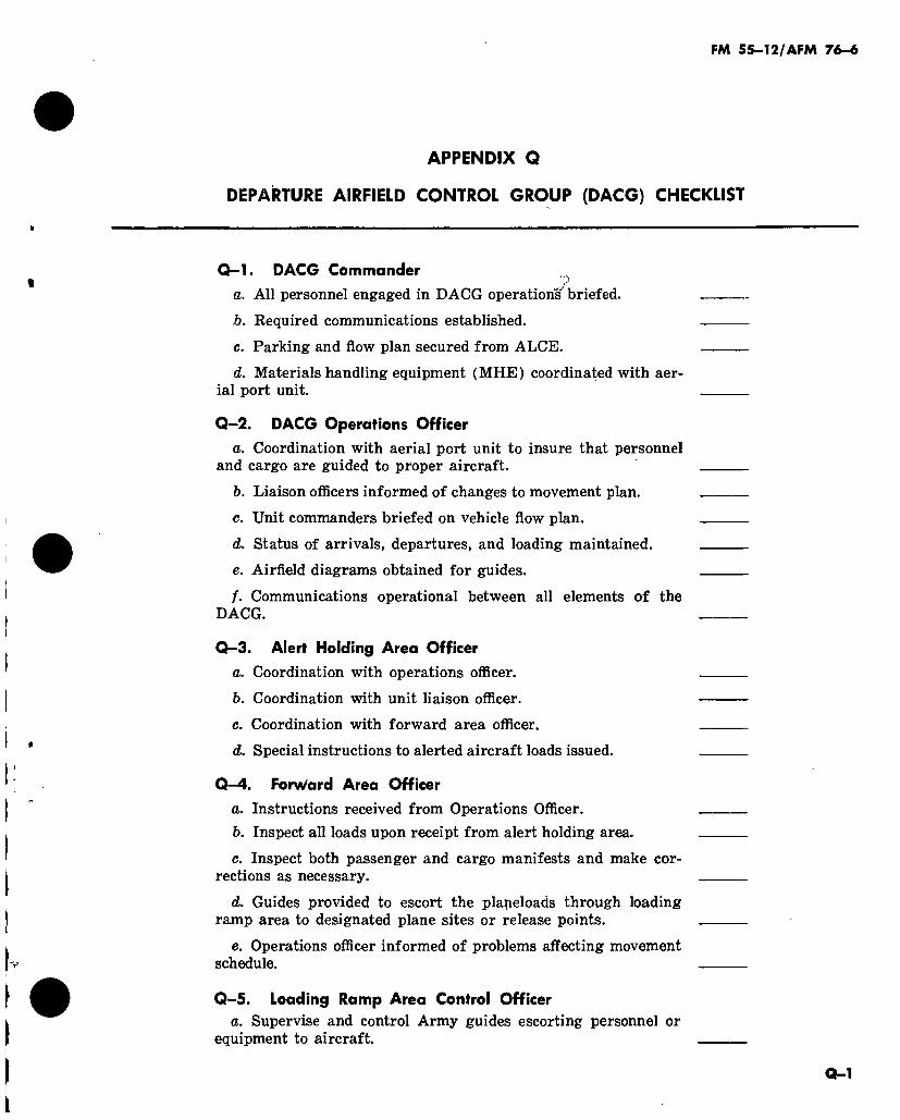
FM 55-12/AFM 76-6
APPENDIX Q
DEPARTURE AIRFIELD CONTROL GROUP (DACG) CHECKLIST
Q—1. DACG Commander
a. All personnel engaged in DACG operation^ briefed.
b. Required communications established.
c. Parking and flow plan secured from ALCE.
d. Materials handling equipment (MHE) coordinated with aer- ial port unit.
Q-2. DACG Operations Officer a. Coordination with aerial port unit to insure that personnel
and cargo are guided to proper aircraft.
b. Liaison officers informed of changes to movement plan.
c. Unit commanders briefed on vehicle flow plan.
d. Status of arrivals, departures, and loading maintained.
e. Airfield diagrams obtained for guides.
/. Communications operational between all elements of the DACG.
Q—3. Alert Holding Area Officer
a. Coordination with operations officer.
b. Coordination with unit liaison officer.
c. Coordination with forward area officer.
d. Special instructions to alerted aircraft loads issued.
Q—4. Forward Area Officer
a. Instructions received from Operations Officer. b. Inspect all loads upon receipt from alert holding area.
c. Inspect both passenger and cargo manifests and make cor- rections as necessary.
d. Guides provided to escort the planeloads through loading ramp area to designated plane sites or release points.
e. Operations officer informed of problems affecting movement schedule.
Q-5. Loading Ramp Area Control Officer a. Supervise and control Army guides escorting personnel or
equipment to aircraft.
Q-l
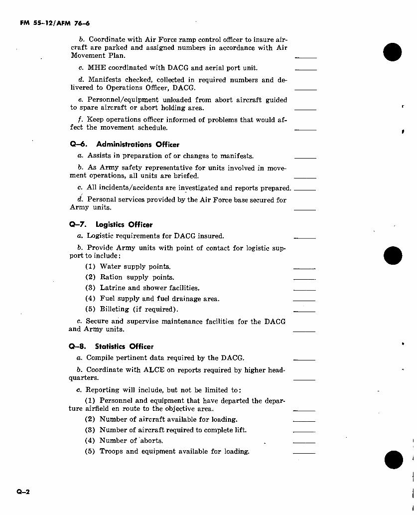
FM 55-12/AFM 76-6
b. Coordinate with Air Force ramp control officer to insure air- craft are parked and assigned numbers in accordance with Air Movement Plan.
c. MHE coordinated with DACG and aerial port unit.
d. Manifests checked, collected in required numbers and de- livered to Operations Officer, DACG.
e. Personnel/equipment unloaded from abort aircraft guided to spare aircraft or abort holding area.
/. Keep operations officer informed of problems that would af- fect the movement schedule.
Q—6. Administrations Officer a. Assists in preparation of or changes to manifests.
b. As Army safety representative for units involved in move- ment operations, all units are briefed.
c. All incidents/accidents are investigated and reports prepared. /
d. Personal services provided by the Air Force base secured for Army units.
Q—7. Logistics Officer
а. Logistic requirements for DACG insured.
б. Provide Army units with point of contact for logistic sup- port to include :
(1) Water supply points. (2) Ration supply points. (3) Latrine and shower facilities. (4) Fuel supply and fuel drainage area. (5) Billeting (if required).
c. Secure and supervise maintenance facilities for the DACG and Army units.
Q—8. Statistics Officer a. Compile pertinent data required by the DACG.
b. Coordinate with ALCE on reports required by higher head- quarters.
c. Reporting will include, but not be limited to: (1) Personnel and equipment that have departed the depar-
ture airfield en route to the objective area. (2) Number of aircraft available for loading. (3) Number of aircraft required to complete lift. (4) Number of aborts. (5) Troops and equipment available for loading.
Q-2

FM 55-12/AFM 76-6
APPENDIX R
ARRIVAL AIRFIELD CONTROL GROUP CHECKLIST
R-l. Commander
a. Brief all personnel engaged in AACG operations.
b. Required communications established.
c. Parking and flow plan secured from ALCE.
d. Materiel handling equipment (MHE) coordinated with aer- ial port unit.
R-2. Operations Officer
a. Coordination with aerial port unit to insure that all person- nel and equipment are cleared from arriving aircraft and guided to release point or holding areas.
b. Current status of arrivals and departures of Army person- nel and equipment at arrival airfield.
c. Airfield diagrams with routes designated to release point and holding areas issued.
d. Communications are operational between all elements of the AACG.
R-3. Loading Ramp Area Control Officer a. Supervise and control Army guides escorting personnel and
equipment from aircraft to release point. b. Coordinate MHE use with the AACG and aerial port unit. c. Keep operations officer informed of problems that would af-
fect the movement schedule. d. Shoring material collected from arriving aircraft.
R-4. Administrations Officer
а. As Army safety representative for units involved in move- ment operations, all units are briefed.
б. All incidents/accidents are investigated and reports prepared. c. Personal services provided by the Air Force base secured for
Army units.
R-5. Logistics Officer a. Logistic requirements for AACG insured.
b. Coordination with Army representative at the appropriate arrival airfield area for ground transportation required to move personnel and equipment to the objective area.
R-l
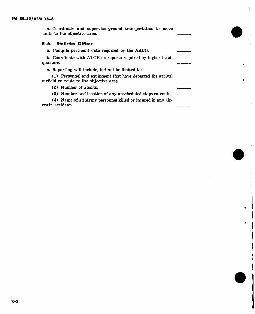
FM 55—12/AFM 76-6
c. Coordinate and supervise ground transportation to move units to the objective area.
R—6. Statistics Officer a. Compile pertinent data required by the AACG.
b. Coordinate with ALCE on reports required by higher head- quarters.
c. Reporting will include, but not be limited to : (1) Personnel and equipment that have departed the arrival
airfield en route to the objective area. (2) Number of aborts. (3) Number and location of any unscheduled stops en route. (4) Name of all Army personnel killed or injured in any air-
craft açcident.
R-2
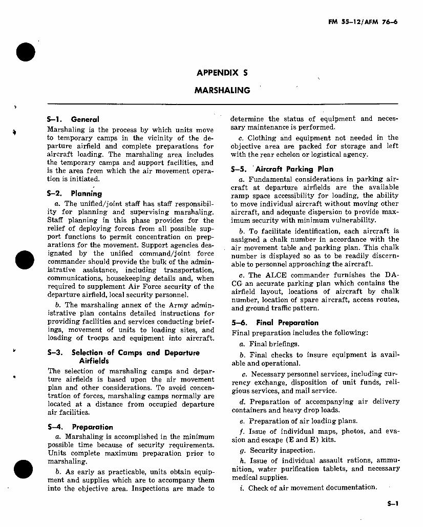
FM 55-12/AFM 76-6
APPENDIX S
MARSHALING
S-l. General Marshaling is the process by which units move to temporary camps in the vicinity of the de- parture airfield and complete preparations for aircraft loading. The marshaling area includes the temporary camps and support facilities, and is the area from which the air movement opera- tion is initiated.
S-2. Planning a. The unified/joint staff has staff responsibil-
ity for planning and supervising marshaling. Staff planning in this phase provides for the relief of deploying forces from all possible sup- port functions to permit concentration on prep- arations for the movement. Support agencies des- ignated by the unified command/joint force commander should provide the bulk of the admin- istrative assistance, including transportation, communications, housekeeping details and, when required to supplement Air Force security of the departure airfield, local security personnel.
b. The marshaling annex of the Army admin- istrative plan contains detailed instructions for providing facilities and services conducting brief- ings, movement of units to loading sites, and loading of troops and equipment into aircraft.
S-3. Selection of Camps and Departure Airfields
The selection of marshaling camps and depar- ture airfields is based upon the air movement plan and other considerations. To avoid concen- tration of forces, marshaling camps normally are located at a distance from occupied departure air facilities.
S-4. Preparation a. Marshaling is accomplished in the minimum
possible time because of security requirements. Units complete maximum preparation prior to marshaling.
b. As early as practicable, units obtain equip- ment and supplies which are to accompany them into the objective area. Inspections are made to
determine the status of equipment and neces- sary maintenance is performed.
c. Clothing and equipment not needed in the objective area are packed for storage and left with the rear echelon or logistical agency.
S-5. Aircraft Parking Plan a. Fundamental considerations in parking air-
craft at departure airfields are the available ramp space accessibility for loading, the ability to move individual aircraft without moving other aircraft, and adequate dispersion to provide max- imum security with minimum vulnerability.
b. To facilitate identification, each aircraft is assigned a chalk number in accordance with the air movement table and parking plan. This chalk number is displayed so as to be readily discern- able to personnel approaching the aircraft.
c. The ALCE commander furnishes the DA- CG an accurate parking plan which contains the airfield layout, locations of aircraft by chalk number, location of spare aircraft, access routes, and ground traffic pattern.
5-6. Final Preparation Final preparation includes the following:
a. Final briefings. b. Final checks to insure equipment is avail-
able and operational. c. Necessary personnel services, including cur-
rency exchange, disposition of unit funds, reli- gious services, and mail service.
d. Preparation of accompanying air delivery containers and heavy drop loads.
e. Preparation of air loading plans. f. Issue of individual maps, photos, and eva-
sion and escape (E and E) kits. g. Security inspection. h. Issue of individual assault rations, ammu-
nition, water purification tablets, and necessary medical supplies.
i. Check of air movement documentation.
S-l

f
4
1
FM 55—12/AFM 76-6
APPENDIX T
SECURITY
T—1. Responsibilities
a. The security and counterintelligence re- quirements involved in air movement operations dictate that the commanders at all echelons of the participating forces establish and enforce strict internal security measures.
b. The unified command/joint force command- er establishes those security measures which must be taken by the units of the component services during each phase of the operation and directs establishment of liaison among all com- mands involved to insure uniformity of security plans, including emergency plans for destruction of classified materials.
c. The commander charged with supporting the marshaling of units provides necessary coun- terintelligence support in and around marshaling areas.
d. All commanders insure that proper secur- ity measures, to include communications secur- ity, are coordinated and enforced by transient units and permanent parties at departure sites and marshaling camps.
e. At the time specified by the unified com- mand/joint force commander, all Army and Air Force units participating or supporting the operation are restricted to designated areas un- til the operation is either executed or canceled.
f. Briefings are conducted at the latest prac- ticable time preceding the operation and in loca- tions which can be closely guarded.
g. Marked maps, operation orders, overlays, or similar items are carried into the objective area only as specifically authorized.
T-2. Passive Defense
a. Concentrations of airlift aircraft in mar- shaling areas, staging bases, and within an air- head provide lucrative targets for the enemy. It is particularly important to observe all passive defense measures that minimize the effect of
enemy action. Consideration must be given to es- tablishing routes of flight and rendezvous points that allow maximum dispersal of aircraft during the air movement phase, yet provide rendezvous points near drop, landing and extraction zones to insure delivery according to schedule.
b. Dispersal of aircraft and troops in marshal- ing areas is essential. Concentration of forces during marshaling must be avoided to retain secrecy of impending operations and to deny lu- crative targets to the enemy. To maintain ade- quate dispersion, Army forces should:
(1) When movement is necessary, move rapidly under cover of darkness, at the latest practicable time, to dispersed areas in the vicin- ity of air facilities.
(2) Make all possible preparations for load- ing prior to arrival at the loading site.
(3) Control movement to loading sites so that the bulk of the personnel arrive after the equipment and supplies are loaded on the air- craft.
T-3. Local Area Security
a. When the Army units are located within the limits of Air Force installations (departure airfields), their unit commanders are responsible to the commander of the departure airfield for the security of their respective areas. The com- mander of the departure airfield is responsible for the overall security of the airfield. The unified/ joint force command exercising operational con- trol/command over the Air Force and Army or- ganization involved may task the Army force commander to provide augmenting security forces.
b. In areas of mutual interest, the command- ers concerned coordinate the security require- ments and define the responsibilities of each force. When aircrews and aerial port/ALCE are the only Air Force personnel resources available at the dispersed departure airfields or staging bases, the Army commander normally assumes
T—1
FM 55—12/AFM 76-«
responsibility for area security, while the Air Force commander is responsible only for point security, such as aircraft.
T—5. Communications-Electronics
a. Each commander is responsible for main- taining the appearance of normalcy in commu- nications traffic, both as to volume and type, par- ticularly radio communications. Greater use is made of telephone and messengers than of radio. However, the appearance of normalcy is main- tained in telephonic traffic utilizing civil circuits, as in the case of radio traffic. Military circuits are checked thoroughly for security before traffic is increased and at regular intervals thereafter. Additional messenger traffic employs unmarked vehicles, normal traffic being maintained with
marked messenger vehicles. The unified com- mand/joint force commander will implement a cover and deception plan only upon approval of the Joint Chiefs of Staff.
b. Communications-electronics silence is main- tained to the extent possible during the air move- ment phase. Conditions under which electronic emitters may be activated are detailed and spe- cific.
c. Once the assault phase is initiated, commu- nications security is practiced as in normal op- erations and is governed by unit SOP, SOI, and SSI. If a withdrawal by air is planned, or forced by enemy action, special communications secur- ity provisions are placed into effect at the time the withdrawal decision is announced.
T-2
By Order of the Secretary of the Army:
CREIGHTON W. ABRAMS General, United States Army
Official : Chief of Staff VERNE L. BOWERS Major General, United States Army The Adjutant General
Distribution : To be distributed in accordance with DA Form 12-11 requirements for US Army/US Air Force Doc-
trine for Airborne Operations (qty rqr block no. 399).
☆ U.S. GOVERNMENT FEINTING OFFICE: 1974—718-218/S087

f
*

\

300002739

»

*¡
» o
;í.
»
t