Embed Size (px)
Citation preview

CURVE is the Institutional Repository for Coventry University
A hybrid optimization approach for sustainable process planning and scheduling Li, X. X. , Li, W. D. , Cai, X. T. and He, F. Z. Author post-print (accepted) deposited in CURVE January 2016 Original citation & hyperlink: Li, X. X. , Li, W. D. , Cai, X. T. and He, F. Z. (2015) A hybrid optimization approach for sustainable process planning and scheduling. Integrated Computer-Aided Engineering, volume 22 (4): 311-326 http://dx.doi.org/10.1016/j.jclepro.2014.10.008 ISSN 1069-2509 ESSN 1875-8835 DOI 10.3233/ICA-150492 Copyright © and Moral Rights are retained by the author(s) and/ or other copyright owners. A copy can be downloaded for personal non-commercial research or study, without prior permission or charge. This item cannot be reproduced or quoted extensively from without first obtaining permission in writing from the copyright holder(s). The content must not be changed in any way or sold commercially in any format or medium without the formal permission of the copyright holders. This document is the author’s post-print version, incorporating any revisions agreed during the peer-review process. Some differences between the published version and this version may remain and you are advised to consult the published version if you wish to cite from it.

A hybrid optimization approach for sustainable process planning and scheduling X.X. Lia, b, W.D. Lib*, X.T. Caic and F.Z. Hec
a College of Informatics, Huazhong Agricultural University, Wuhan 430072, P.R.China b Faculty of Engineering and Computing, Coventry University, CV1 5FB, U.K. c School of Computer Science and Technology, Wuhan University, Wuhan 430072, P.R.China
Abstract. Process planning and scheduling are important stages in manufacturing, and good strategies can significantly im-prove the energy performance of manufacturing to achieve sustainability. In this paper, an innovative optimization approach has been developed to facilitate sustainable process planning and scheduling. In the approach, honey-bee mating and annealing processes are simulated to optimize multi-objectives including energy consumption, makespan and the balanced machine utili-zation. Experiments on practical cases show that the optimization results from this approach are promising in comparison with those from a genetic algorithm, a honey bee mating optimization algorithm, ant colony optimization and a simulated annealing algorithm, respectively.
Keywords: Honey bee mating optimization, Simulated annealing, Sustainable manufacturing, Process planning, Scheduling
*Corresponding author: W.D. Li, Faculty of Engineering and Computing, Coventry University, CV1 5FB. E-mail: [email protected].
1. Introduction
With the rapidly growing production demands, manufacturing has become one of the largest energy consuming sectors [50]. Statistics has shown that the greenhouse gas emitted from the usage of energy sources such as electricity, coal, oil and gas during manufacturing accounts for more than 37% even 50% of the world’s total greenhouse gas emissions [38]. In order to balance the multi-faceted dimen-sions of economic growth and environmental protec-tion, a series of regulations and guidelines, such as the European standard EN 16001:2010 [10], life-cycle carbon labeling outlined by the life-cycle as-sessment frameworks of the ISO 14040: 2006 and ISO 14044: 2006 [19, 20], and the Publicly Available Specification 2050: 2008 (PAS 2050) [47], have been developing. For manufacturing companies, based on the regulations and guidelines, energy efficiency can be improved and the greenhouse gas emission level can be minimized so as to embrace “Competitive Sustainable Development” and shoulder “Extended Producer Responsibilities (EPR)” [24] effectively. Meanwhile, energy saving is also increasingly vital
for customers in choosing products. For instance, a survey indicated that 67% of UK consumers are more likely to buy a product with a lower life-cycle energy consumption and 44% would switch to such a green-er product even if the brand/model is not their first choice [54]. Therefore, these economic, environmen-tal and competitive factors are motivating manufac-turing companies to take measures to minimize their energy consumption and achieve sustainable manu-facturing.
A large number of studies [49] have indicated that careful process planning and scheduling for manufac-turing systems will realize great energy savings. That is, process planning and scheduling are critical func-tions not only to minimize cost, improve adaptability, responsiveness and robustness but also to enhance the sustainability of manufacturing processes. There-fore, effective process planning and scheduling is imperative to achieve sustainable manufacturing.
In order to realize sustainable manufacturing by optimizing process planning and scheduling, a multi-objective optimization problem of minimizing overall energy consumption, makespan and machine utiliza-tion in a job shop is considered in this paper. An in-

novative optimization approach for sustainable pro-cess planning and scheduling is presented. In this approach, a 5-phase energy consumption model and an effective hybrid honey-bee mating optimization and simulated annealing (HBMO-SA) algorithm are developed to optimize the overall energy consump-tion in process planning and scheduling.
This research is a comprehensively extended ver-sion from a previous work of authors [31], and sig-nificant improvements are reflected from the follow-ing aspects. First, a detailed literature survey is given. Second, a model of integrated process planning and scheduling for dynamic manufacturing is presented in detail. Finally, the developed HBMO-SA approach is benchmarked with other classic heuristic algo-rithms to demonstrate its merits and effectiveness.
The remainder of this paper is organized as fol-lows. In Section 2 related work is reviewed. In Sec-tion 3, process planning and scheduling are first rep-resented and then its energy consumption model is presented. Then, the HBMO-SA approach is present-ed in Section 4. In Section 5, case studies and com-parisons with other heuristic algorithms are given. Finally, a conclusion is drawn in Section 6.
2. Related works
In recent years, both sustainable manufacturing and process planning and scheduling have attracted many researchers’ attention. This section presents a review of the related work from the viewpoint of sustainable manufacturing and heuristic algorithms applied to sustainable manufacturing applications.
2.1. Sustainable manufacturing
The research works focusing on sustainable manu-facturing can be viewed from four different perspec-tives, i.e., machining process, machine design, eco-product development and manufacturing system.
(1) Machining process
Most of the research works were dedicated to quantifying the energy consumed in machining. Some research works focus on developing machine specific models of unit process energy consumption. In the existing models, the most representative one was developed by Gutowski et al [13]. The specific energy consumption (SEC) of machining processes was modeled as a function of the process rate by ana-lyzing the unit process energy for the processes in an exergy framework [13]. However, in the model, the
specifications for the fixed power P0 and the constant k were not given. Taking up the missing specification in the model of Gutowski et al., researchers devel-oped some improved energy consumption models such as the unit process energy consumption model created by Li and Kara [25], the SEC model provided by Diaz et al [8] and the energy consumption model for milling processes developed by Li et al [28].
Different from the research works on modeling unit process energy consumption, some other re-search works concentrated on modeling the total en-ergy consumption in machining. For instance, Diaz et al. modeled the total energy consumption in machin-ing as a function of average power and the processing time [8]. However, the impact of machine tools, work-piece materials and cutting variables were ne-glected. Mori et al. presented an energy consumption model which involved the energy consumption of several processes: positioning and acceleration the spindle, returning the spindle to the tool change posi-tion after machining and stopping the spindle [36]. He et al. divided the total energy consumption of Numerical Control (NC) machining into five parts, i.e. the energy consumption of spindle, axis feed, tool change system, coolant pump, and the fixed energy consumption. Each part can be estimated by the cor-responding power characteristics and the parameters extracted from the NC codes [14]. However, this model can only be used to help NC code designers make decisions regarding energy-efficient NC pro-grams because it is based on the NC programming but ignores some other energy factors consumed by chillers, swarf conveyors and lubrication of machines etc. Aiming at predicting direct electrical energy re-quirements in machining tool-paths, Balogun and Mativenga divided the energy states of machine tools into three categories: basic, ready and cutting states, where the energy is demanded to activate required machine components, making the axis and tool to be ready for action and remove work-piece material respectively [4]. However, this model is limited be-cause the energy consumed by the machine axis has not been taken into account. Duflou et al. [9] studied the energy efficiency on the machining factory level. However, the energy consumption of preparation phase in scheduling is neglected.
(2) Machine design
The research works focus on developing and de-signing more energy-efficient machines and equip-ment. The most representative work is the standard on energy saving for machine tools drafted by the

International Standard Organization (i.e. ISO/WD14955-1) [21]. Two informative annexes related to environmentally relevant improvements and well tried mechanical and electrical components are listed in the standard.
(3) Eco-product development
The related works concentrate on modeling and reducing the embodied product energy (EPE) during manufacturing to support energy efficient manufac-turing. A modeling framework was introduced by Seow et al. to represent the total energy required to manufacture a unit product [44]. Another model was built by Kara et al. to assess the impact of global manufacturing on the EPE [26].
(4) Manufacturing system
The energy efficiency of a manufacturing system is improved mainly by two methods. One is simula-tion based method which improves the energy effi-ciency by simulating electricity consumption and the process chain [16]. The other is optimization based method which improves the energy efficiency by optimizing the single machine scheduling [37] and the flow shop scheduling [5].
From the literature survey, it can be observed that energy consumption and sustainability are related to the different stages of product development and manufacturing life-cycle. Hence, as an important sector of manufacturing, process planning and sched-uling is of great importance for energy saving.
2.2. Algorithms for process planning and scheduling
In the past decade, a number of research works ap-peared to develop heuristic algorithms [46]. Among these algorithms, GA is the most popular one [2, 3, 15, 22, 32, 55]. It was used to generate the feasible sequences of operations and identify the optimal tool sequence in process planning for machining (e.g., milling). It is proved that GA has a good global search capability [6, 23, 33, 35, 40, 42, 43]. However, the algorithm is liable to be trapped in a local opti-mum. SA is another algorithm widely used in process planning and scheduling. It was applied to search the optimal solution in process planning and scheduling [29]. SA can identify a good solution quickly but may fluctuate around the local optima due to the lack of the memory mechanism. Additionally, several swarm intelligence algorithms such as ACO [12], particle swarm optimization (PSO) [17, 18, 45, 48, 52, 53] and HBMO [51], were applied to process
planning and scheduling. Compared with the other most known heuristic algorithms such as GA, SA and ACO, HBMO has a better performance in computa-tional effectiveness and stability.
HBMO is a swarm intelligence algorithm which was developed by modeling the mating behavior of honey bee swarm. It is known that the intelligent behaviors of bees include mating, foraging, dance, nest site selection and so on. Hence, different intelli-gence algorithms can be obtained by modeling dif-ferent behaviors of honey bee swarm. For instance, the artificial bee colony (ABC) algorithm [41] was developed by simulating foraging behavior of honey bees. Different from these algorithms, HBMO is in-spired by the mating behavior of honey bees.
After HBMO was first presented by Abbass [1] to address the propositional satisfiability problems, the algorithm was applied to various domains. Koudil et al. [27] applied HBMO to solve partitioning and scheduling problems in code design. Curkovic and Jerbic [7] used HBMO to address the non-linear dio-phantine equation benchmark problem. Haddad et al. applied HBMO to optimize reservoir operation and distribution systems. Amiri and Fathian [11] im-proved HBMO to solve a real-world problem of an Internet bookstore market segmentation, and then, applied the algorithm in clustering. Marinakis et al. [34] used a hybrid algorithm combining HBMO and Greedy randomized adaptive search procedure to solve the vehicle routing problem. Niknam et al. [39] presented an improved HBMO for multi-objective placement of renewable energy resources. Wen et al. [51] first applied HBMO to address process planning problem and obtained a good process plan with min-imal global machining cost in reasonable time.
Although HBMO can be used to solve optimiza-tion problems and good solutions can be obtained quickly, it often converges to local optima. Therefore, an improved HBMO method is required to overcome this shortcoming.
3. Sustainable Process Planning and Scheduling Approach
3.1. Representations for process planning and scheduling
Process planning and scheduling, which bridges Computer Aided Design (CAD) and Manufacturing Execution Systems (MES), is a critical function to minimize cost, improve adaptability, responsiveness,

robustness and sustainability of manufacturing pro-cesses.
The major considerations in process planning in-clude: (1) generating machining operations based on the features of a part to meet desired functional speci-fications and achieve good manufacturability, (2) identifying machining resources applicable to the operations, and (3) determining the set-up plan and operation sequence according to some criteria such as makespan, energy efficiency and so on. Therefore, a process plan for a part can be represented by a series of machining operations, applicable resources for the operations, set-up plans, operation sequence, etc. A set-up can be generally defined as a group of opera-tions that are manufactured on a single machine with the same fixture.
Based on the generated process plans of parts, the scheduling task is to assign the parts and their ma-chining operations to specific machines to be execut-ed in different time slots, targeting at a good shop floor performance, such as the shortest makespan, the most balanced machine utilization, the least total tar-diness, etc. A Gantt chart has been popularly used to represent a schedule of a group of parts, illustrated in Fig. 1. In the Gantt chart, the order in which the parts and their operations are carried out is laid out and the dependencies of the tasks are managed. The X axis of the Gantt chart represents time. Each row in the Y axis represents a machine and the specific arrange-ment for the operations of the parts on the machine. A machine is comprised of a number of time slots, which can be further classified into idle time slots, preparation time slots for machining operations (fur-ther including the set-up time, the machine change time, or the tool change time), and machining time slots of operations.
As a consequence of the above, a part can be manufactured by different process plans. A group of alternative process plans can be generated using two strategies: processing flexibility and operation se-quencing flexibility. Processing flexibility refers to the possibility of performing an operation on alterna-tive machines with alternative set-ups or tools. Opera-tion sequencing flexibility corresponds to the possi-bility of interchanging the sequence in which the op-erations are performed. For a group of parts, alterna-tive schedules can be created based on scheduling flexibility, which relates to the possibility of arrang-ing different schedules to manufacture the parts and the operations.
3.2. Energy consumption modeling for process planning and scheduling
It has been known that there are a group of ma-chines in the machining resources. Following the pro-cess planning and scheduling solution, one or more operations will be executed on the same machine. For a machine, its power profile is illustrated in Fig. 2, which consists of startup phases, idle phases, prepara-tory phases, working phases, and shutdown phases.
Hence, the energy consumption of a machine can be separated into the corresponding five segments.
The energy consumption during the startup phase can be computed as:
_1( ). ( )i
i
T
i startup iTE M startup P M dt= ∫ where E(Mi).startup represents the energy con-
sumed during the startup phase, Pstartup(Mi) represents the power demand of the i-th machine during the startup phase, Ti and Ti_1 stand for the start and end time of the startup phase.
Fig. 1. A Gantt chart for scheduling parts and machining operations.
(1)
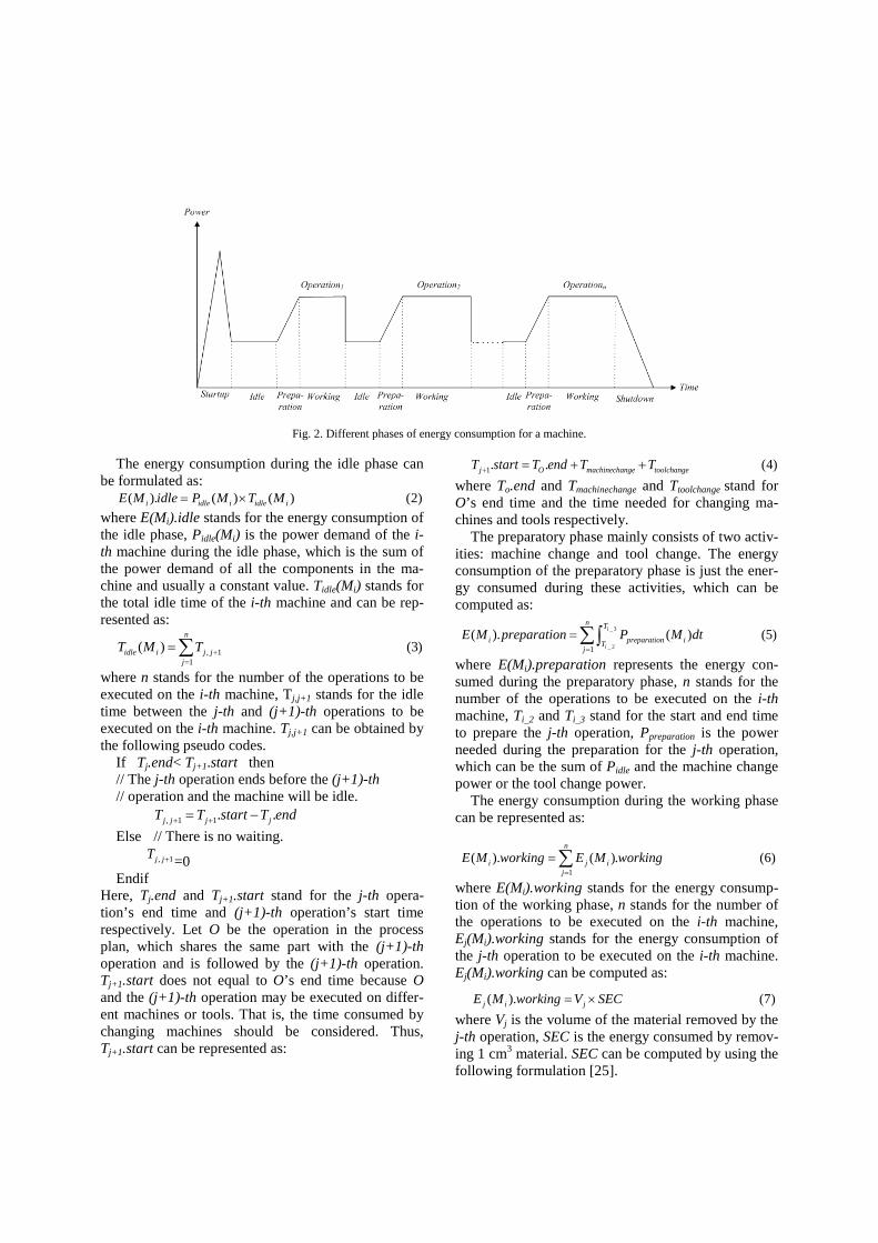
Fig. 2. Different phases of energy consumption for a machine.
The energy consumption during the idle phase can be formulated as:
( ). ( ) ( ) (2)i idle i idle iE M idle P M T M= ×where E(Mi).idle stands for the energy consumption of the idle phase, Pidle(Mi) is the power demand of the i-th machine during the idle phase, which is the sum of the power demand of all the components in the ma-chine and usually a constant value. Tidle(Mi) stands for the total idle time of the i-th machine and can be rep-resented as:
, 11
( ) (3)n
idle i j jj
T M T +=
=∑where n stands for the number of the operations to be executed on the i-th machine, Tj,j+1 stands for the idle time between the j-th and (j+1)-th operations to be executed on the i-th machine. Tj,j+1 can be obtained by the following pseudo codes.
If Tj.end< Tj+1.start then // The j-th operation ends before the (j+1)-th // operation and the machine will be idle.
, 1 1. .j j j jT T start T end+ += − Else // There is no waiting.
, 1j jT + =0 Endif
Here, Tj.end and Tj+1.start stand for the j-th opera-tion’s end time and (j+1)-th operation’s start time respectively. Let O be the operation in the process plan, which shares the same part with the (j+1)-th operation and is followed by the (j+1)-th operation. Tj+1.start does not equal to O’s end time because O and the (j+1)-th operation may be executed on differ-ent machines or tools. That is, the time consumed by changing machines should be considered. Thus, Tj+1.start can be represented as:
1. . (4)j O machinechange toolchangeT start T end T T+ = + +
where To.end and Tmachinechange and Ttoolchange stand for O’s end time and the time needed for changing ma-chines and tools respectively.
The preparatory phase mainly consists of two activ-ities: machine change and tool change. The energy consumption of the preparatory phase is just the ener-gy consumed during these activities, which can be computed as:
where E(Mi).preparation represents the energy con-sumed during the preparatory phase, n stands for the number of the operations to be executed on the i-th machine, Ti_2 and Ti_3 stand for the start and end time to prepare the j-th operation, Ppreparation is the power needed during the preparation for the j-th operation, which can be the sum of Pidle and the machine change power or the tool change power.
The energy consumption during the working phase can be represented as:
where E(Mi).working stands for the energy consump-tion of the working phase, n stands for the number of the operations to be executed on the i-th machine, Ej(Mi).working stands for the energy consumption of the j-th operation to be executed on the i-th machine. Ej(Mi).working can be computed as:
( ). (7)j i jE M working V SEC= ×
where Vj is the volume of the material removed by the j-th operation, SEC is the energy consumed by remov-ing 1 cm3 material. SEC can be computed by using the following formulation [25].
_ 3
_ 21( ). ( ) (5)i
i
n T
i preparation iTj
E M preparation P M dt=
=∑∫
1( ). ( ). (6)
n
i j ij
E M working E M working=
=∑
where the coefficient C0 is related to the work-piece material, tool geometry and spindle drive characteris-tics; C1 depends on how the machine tool is designed including its motor and transmission system; MRR stands for material removal rate for the working phase, which is influenced mainly by four types of factors, i.e., tool conditions, work-piece material, cutting pa-rameters and cutting environment. For C0 and C1, multiple machines’ corresponding coefficients were provided by Kara and Li [25]. MRR can be obtained using the cutting volume and time.
The energy consumed during the shutdown phase can be computed as:
_ 5
_ 4
(9)( ). ( )i
i
T
i shutdown iTE M shutdown P M dt= ∫
where E(Mi).shutdown represents the energy con-sumption of the shutdown phase, Ti_4 and Ti_5 stand for the start and end time for switching off the i-th machine respectively, Pshutdown(Mi) stands for the pow-er consumption of the i-th machine during the shut-down phase.
Based on the energy consumption of the above phases, the total energy consumption of a machine can be represented below:
( ) ( ). ( ). ( ).( ). ( ). (10)
i i i i
i i
E M E M startup E M idle E M preparationE M working E M shutdown
= + + ++
where E(Mi) stands for the total energy consumption of the i-th machine.
Therefore, if there are m machines to be used in the process planning and scheduling, the overall energy consumed by all the machines to machine all the parts is:
1( ) (11)
m
Group ii
E E M=
=∑
3.3. Process planning and scheduling criteria
The energy consumption for a process planning and scheduling, as an essential criterion, has been defined above. Some other criteria based on time to evaluate the performances of process plans and schedules are defined in the following, which consists of the makespan and the balanced level of the machine utili-zation. In order to present the criteria, two assump-tions are made. One is the number of machine (m). The other is the number of operations (n) to be exe-cuted on the machine.
Makespan means the maximum interval time spent to machine all the parts. It can be defined in the fol-lowing:
1( ( )) (12)
m
iiMakespan Max T M
==
where T(Mi) is the total utilization time of the i-th machine, which is composed of multiple startup, idle, preparation and working phases. That is, T(Mi) can be represented as:
( ) ( ). ( ).( ). ( ). (13)
i i i
i i
T M T M startup T M preparationT M idle T M working= + +
+where T(Mi).startup, T(Mi).preparation, T(Mi).idle, and T(Mi).working stand for the time of the corre-sponding phases. Let Oij be the j-th operation to be executed on the i-th machine.
1( ). ( . . _ ) (14)
n
i ij ijj
T M startup O Startup O Startup Index=
= ×∑where Oij.Startup represents whether the i-th machine is started up, Oij.Startup_Index is the time index for each start up.
0.
1(15)ij
if the i th machine has been started upO Startup
if not−
=
1( ). ( . _ . _ ) (16)
n
i ij ijj
T M preparation O MC T O TC T=
= +∑where Oij.MC_T and Oij.TC_T represent the time for machine change and tool change respectively.
T(Mi).idle can be computed by using Eq. 3. T(Mi).working is just the time used to execute all the operations on the i-th machine. Thus, it can be com-puted as:
1( ). ( . _ ) (17)
n
i ijj
T M working O Working T=
=∑where Oij.Working_T represents the time used by the i-th machine to execute the j-th operation.
The standard deviation concept is introduced here to evaluate the balanced machine utilization.
1( )
(18)
m
ii
T M
mχ ==
∑
2
1_ ( ( ) ) (19)
m
ii
Utilization level T M χ=
= −∑
Based on the above functions, the weighted addi-tive utility function is used to solve multi-objective optimization problem. The total weighted perfor-mance criteria (TWPC) can be described as:
1 2 3 _level (20)GroupTWPC w E w Makespan w Utilisation= + +
where w1, w2 and w3 are the weights. The value of each weight is between 0 and 1, and the sum of them equals to one.
10 (8)CSEC C
MRR= +

4. Hybrid HBMO-SA algorithm
4.1. Overview
HBMO is a recently developed evolutionary algo-rithm. It is inspired by the process of real honey-bee mating and has been applied in some combinatorial optimization problems such as the traveling salesman problem, vehicle routing problem and the process planning problem. Furthermore, all the results have shown that better local optimum solutions can be found quickly using HBMO. However, it has also been observed that HBMO is liable to converge to local optima. Fortunately, SA can be used to compen-sate for this shortcoming because it can accept some probability. Consequently, in this paper, the strengths of HBMO and SA are combined to achieve the global optimization effectively.
The proposed HBMO-SA consists of two phases: HBMO-phase and SA-phase. In the HBMO-phase, the honey-bee mating process is simulated to generate a population. Good chromosomes in the population are then selected as the initial current process plans and schedules for the SA to search the optimal or near-optimal process plans and schedule. The flowchart of the proposed hybrid HBMO-SA is shown in Fig. 3.
In the hybrid HBMO-SA, the encoding scheme for each individual consists of four parts: operation se-quencing, machine sequencing, tool sequencing and tool approaching direction (TAD) sequencing. In the operation sequencing, each position corresponds to an operation number. That is, the i-th element of the op-eration sequence represents the operation that will be executed. The second part is machine sequencing where the i-th position corresponds to the machine number used by the i-th operation. The third part is tool sequencing that is just the tool number used by the corresponding operation. The fourth part is TAD sequencing used by the operations.
In addition, the reciprocal of the objective function is chosen as the fitness function (cf. equation 21) to follow the rule that the individual with a greater fit-ness has a higher chance to be chosen. The fitness function for a solution is as follows:
1 (21)FitnessTWPC
=
4.2. Honey-bee mating algorithm: Phase 1
The HBMO algorithm has been developed by simu-lating the honey-bee mating process. In the mating
process, the queen flies far from the nest. During the mating flight, the strong drones catch up with the queen and mate with her. After the queen’s sperma-theca is full of sperms, she will fly back to the nest and lay eggs. Each time the queen lays eggs, she ran-domly retrieves a sperm from her spermatheca to ferti-lize the eggs and a set of broods are generated. Then, the works will take care of and improve the broods (e.g. feeding them with royal jelly). If a brood is better than the queen, it will be the new queen and starts its mating flight. The final queen obtained after all the mating flights is just the optimization result.
As a consequence of the above, the HBMO algo-rithm should contain a number of different procedures which correspond to the different phases of the honey-bee mating process. The HBMO algorithm can be described as follows:
Step 1: Initialization consists of the following steps: Step 1.1: The parameters of HBMO, including
size of queen’s spermatheca, number of drones, workers, number of mating flights, the queen’s flight speed at the t-th mating Speed(t) and its drop coefficient α, are initial-ized respectively.
Step 1.2: The population of the honey bees (i.e., initial solutions) is created to configure the initial hive. In the proposed algorithm, the initial population, where each individual is composed of the operation sequence, and the selected machine, tool and TAD, is gen-erated using a GA. Then, the reciprocal of the objective function is used as the fitness function and the fitness values of all mem-bers are calculated by Eq. 21. According to the fitness values, the queen (i.e. the best schedule in the initial population) with the maximum fitness value is selected. All the other members of the population are used as drones.
It should be pointed out that the GA used to gener-ate the initial population is the basic version of GA. It consists of three operators: selection, crossover and mutation. The roulette-wheel selection is used as the selection operator to choose individuals for crossover and mutation. The two-point crossover is implement-ed to crossover the first parts of two chromosomes. A specified probability is then used in the mutation op-erator to judge whether the mutation will be executed. If the probability is greater than a random number, the machine, tool and TAD used by the corresponding operation will mutate.

Step 2: Drones are selected to mate with the queen. A drone mates probabilistically by using an annealing function as follows:
( ) (22)f
Speed te r− ∆
>where △f is the difference between the fitness of the drone and queen, which can be evaluated by using the Eq. 21, r is between 0 and 1 and randomly generated, Speed(t) is the queen’s flight speed at the t-th mating , the queen’s flight speed decays with the mating ac-cording to the following equation:
( 1) ( ) (23)Speed t Speed tα+ = ×where α is between 0 and 1.
Based on this probabilistic rule in Eq. 22, the strong drones with the great fitness value are selected and their sperms are stored in the queen’s spermatheca. This selection procedure will not stop until the queen’s spermatheca is full.
Step 3: A brood is generated by crossovering the queen’s genotype with the sperm selected from the queen’s spermatheca. The crossover operator includes the following steps:
Step 3.1: A crossover position P is chosen ran- domly. The queen and the selected sperm are separated into left and right parts from the crossover point.
Step 3.2: Both the right part of the queen and the left part of the selected sperm are copied to generate a brood.
Step 3.3: The brood is checked to find out those genes that are redundant or lost.
Step 3.4: The redundant genes in the brood are replaced with the lost ones. The machines, tools and TADs are adjusted according to the operations. The new brood is obtained.
Step 4: For each brood, a worker (i.e. a local search heuristics) is chosen randomly to improve it. If the improved brood (i.e., the new solution) has a greater fitness than that of the current queen, it will replace the queen. All the other broods will take part in the next mating flight as drones. The improvement is achieved by three operators: mutation, adjacent swapping and shift.
• The mutation operator is achieved mainly by two steps. First, an operation in the current so-lution is selected randomly. Then, the corre-sponding machine and tool are renewed from the candidate lists.
• The adjacent swapping is realized by ex-changing two adjacent operations in the cur-rent solution. Meanwhile, the corresponding machines, tools and TADs are exchanged.
Create the initial honey bee population and select the best one as the queen
Select strong drones from the current population and save their sperms in the queen’s spermatheca until its
spermatheca is full
Generate a new brood by crossovering the queen’s genotype and the sperms stored in its spermatheca
Improve the brood and select the individual which is better than the queen to replace it
The maximum number of mating flight N
Y
Select the queen generated by HBMO as the initial solution S0 for SA
Determine the start and end temperatures Tstart and Tend and let Tstart be T
Generate a new schedule S’, ∆=PC(S’)-PC(S)
∆≤0 || e-abs(∆)/T>rand
Y
S=S’ N
T=α×T
T≤Tend N
Y
HBMO
SA
The best solution
Fig. 3. Flowchart of the hybrid HBMO-SA algorithm.
• The shift operator is done by removing an op-eration from its present position to insert it at another position. The machine, tool and TAD used by the operation will also be removed to the corresponding positions.
Based on the above operators, four workers are generated. The first three workers correspond to muta-tion, adjacent swapping and shift respectively. The fourth worker simultaneously employs two operators: mutation and adjacent swapping.

Step 5: If the number of mating flight is still not more than the maximum which has been defined in step1.1, a new mating flight will begin. That is, Steps 2-4 will be repeated until the number of mating flight reaches the largest number.
4.3. Simulated annealing: Phase 2
In the second phase of the hybrid HBMO-SA ap-proach, the SA algorithm is used to jump out of local optima and achieve a better localized search. Its pro-cesses are described as follows.
Step 1: The individual with the maximum fitness value is first selected from the populations generated by HBMO. The selected individual is used as the ini-tial current schedule S0 for the SA.
Step 2: The start and end temperatures Tstart and Tend are determined. Tstart is taken as the current tempera-ture T.
Step 3: A new temporary schedule S’ is generated by using two types of mutation strategies which are listed as follows:
• Two operations in the current schedule S are chosen randomly and exchanged. The ma-chines, tools and TADs used by the operations are exchanged too.
• An operation in S is selected. Then, the ma-chine, tool and TADs used by the selected op-eration are changed by referring the candidate list.
Step 4: One of the performance criterion functions defined above is used to compute the difference be-tween the performance criteria of S’ and S. Let PC represent a performance criterion.
( ') ( )PC S PC S∆ = −
If ( )
0 ||abs
Te rand− ∆
∆ ≤ > // 0 1rand< < 'S S=
End T Tα= × // 0 1α< < Step 5: Steps 3-4 will be repeated until T<=Tend.
5. Case studies and discussions
In this section, three groups of parts from practical manufacturing are presented to validate the effective-ness and feasibility of the proposed approach. In the case studies, the machines tested by Kara and Li were used as the machining resources [25]. The experi-ments were performed on the Windows 7 operating system with Intel Dual-core CPU at 2.10 GHz and
3.00GB of main memory. The simulation was carried out by using the Matlab programming language.
In order to select the appropriate parameters, a number of different alternative values of the proposed algorithm’s parameters were tested. The selected pa-rameters of HBMO are: size of queen’s spermatheca equals to 60, number of drones equals to 100, number of mating flights equals to 400, the initial speed(t) and α in equation (23) are 1000 and 0.85 respectively. For the SA, the selected parameters are: the start and end temperatures Tstart and Tend equal to 1000 and 3.5116e-025 respectively, and α equals to 0.9.
It should be pointed out that some assumptions [29, 30] that are commonly used in most of the previous research works regarding scheduling were still taken for this study. The assumptions include: • Parts are independent, and part preemption is not
allowed; • The sequence of the operations of each part
complies with manufacturing constraints; • All parts, machines and tools are available at
time zero simultaneously; • Each operation is performed on a single machine,
and each machine can only execute an operation at a time;
• Machines are continuously available for produc-tion;
• If a machine or a tool is broken down, or a new part is inserted, the algorithm can re-start and generate new process plans and a schedule due to the efficient optimization performance of the al-gorithm;
• The time for a set-up is identical and independ-ent of specific operations. The time for a ma-chine change or a tool change follows the same assumption.
5.1. Case study 1
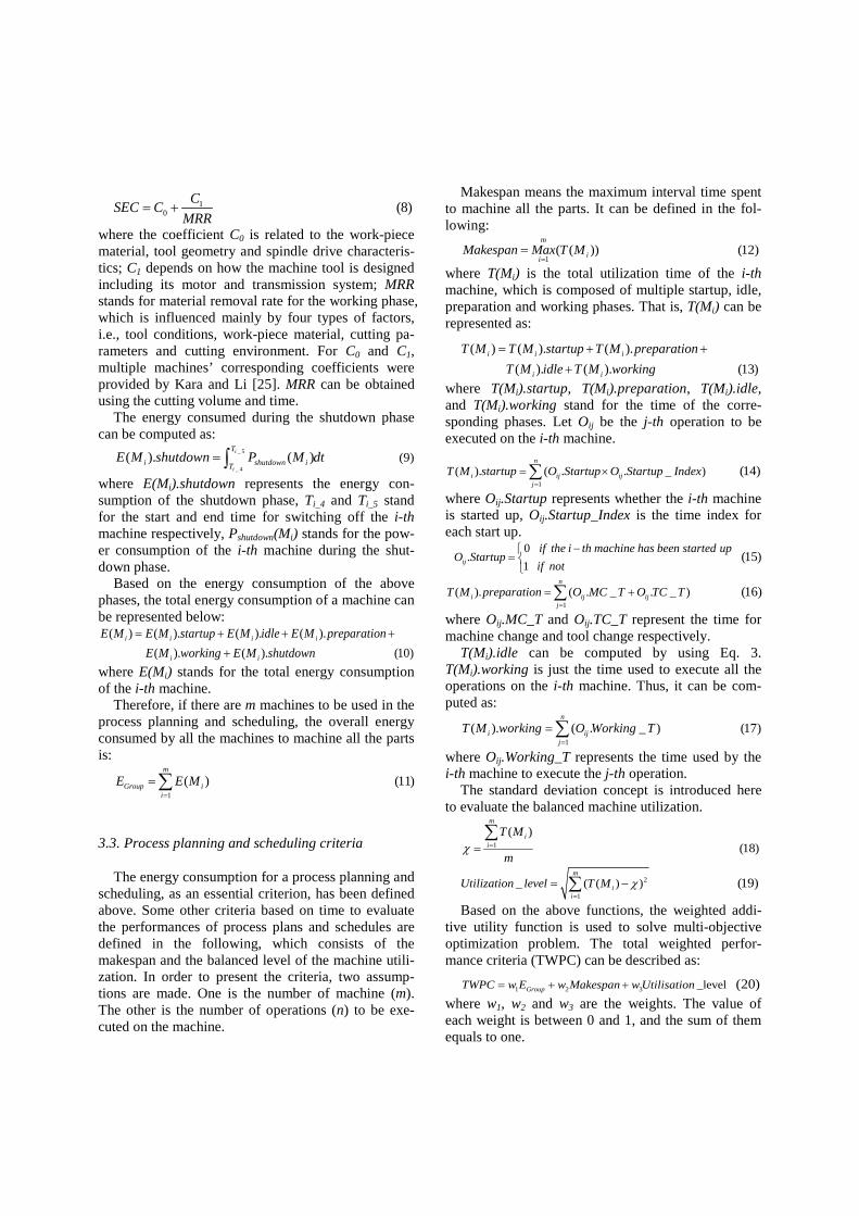
The first case consists of three parts which are shown in Fig. 4. This group of parts has 38 machining features.
For the parts, various experiments were conducted for three different conditions. • 1PC Makespan=
where PC1 represents the first performance crite-rion (to achieve the minimum makespan).
• 2 _PC Energy Consumption=
where PC2 represents the second performance cri-terion (to achieve the minimum energy consump-tion).
• The third performance criterion is used to opti-mize energy consumption and the balanced utili-zation simultaneously, and thus consists of both of them. It can be represented as:
3 1
3
__
PC w Energy Consumptionw Utilization Level
= × +×
where PC3 stands for the third performance criterion, and w1 and w3 stand for the weights of the two criteria. Both w1 and w3 are set 0.5 in the experiments to take the energy consumption and utilization into account simultaneously.
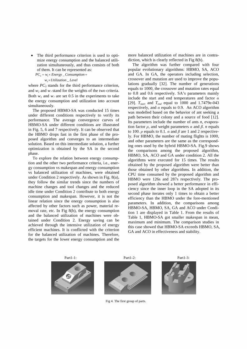
The proposed HBMO-SA was conducted 15 times under different conditions respectively to verify its performance. The average convergence curves of HBMO-SA under different conditions are illustrated in Fig. 5, 6 and 7 respectively. It can be observed that the HBMO drops fast in the first phase of the pro-posed algorithm and converges to an intermediate solution. Based on this intermediate solution, a further optimization is obtained by the SA in the second phase.
To explore the relation between energy consump-tion and the other two performance criteria, i.e., ener-gy consumption vs makespan and energy consumption vs balanced utilization of machines, were obtained under Condition 2 respectively. As shown in Fig. 8(a), they follow the similar trends since the numbers of machine changes and tool changes and the reduced idle time under Condition 2 contribute to both energy consumption and makespan. However, it is not the linear relation since the energy consumption is also affected by other factors such as power, material re-moval rate, etc. In Fig 8(b), the energy consumption and the balanced utilization of machines were ob-tained under Condition 2. Energy saving can be achieved through the intensive utilization of energy efficient machines. It is conflicted with the criterion for the balanced utilization of machines. Therefore, the targets for the lower energy consumption and the
more balanced utilization of machines are in contra-diction, which is clearly reflected in Fig 8(b).
The algorithm was further compared with four popular evolutionary algorithms: HBMO, SA, ACO and GA. In GA, the operators including selection, crossover and mutation are used to improve the popu-lations gradually [32]. The number of generations equals to 1000, the crossover and mutation rates equal to 0.8 and 0.6 respectively. SA’s parameters mainly include the start and end temperatures and factor α [29]. Tstart and Tend equal to 1000 and 1.7479e-043 respectively, and α equals to 0.9. An ACO algorithm was modelled based on the behavior of ant seeking a path between their colony and a source of food [12]. Its parameters include the number of ants n, evapora-tion factor ρ, and weight parameters α and β. n equals to 100. ρ equals to 0.1. α and β are 1 and 2 respective-ly. For HBMO, the number of mating flights is 1000, and other parameters are the same as the correspond-ing ones used by the hybrid HBMO-SA. Fig.9 shows the comparisons among the proposed algorithm, HBMO, SA, ACO and GA under condition 2. All the algorithms were executed for 15 times. The results obtained by the proposed algorithm were better than those obtained by other algorithms. In addition, the CPU time consumed by the proposed algorithm and HBMO were 126s and 287s respectively. The pro-posed algorithm showed a better performance in effi-ciency since the inner loop in the SA adopted in its second phase iterates only 1 times to obtain a better efficiency than the HBMO under the fore-mentioned parameters. In addition, the comparisons among HBMO-SA, HBMO, SA, GA and ACO under Condi-tion 1 are displayed in Table 1. From the results of Table 1, HBMO-SA got smaller makespan in mean, maximum and minimum. The comparison studies in this case showed that HBMO-SA exceeds HBMO, SA, GA and ACO in effectiveness and stability.
Fig 4. The first group of parts.
Part1-1: Part1-2: Part1-3:
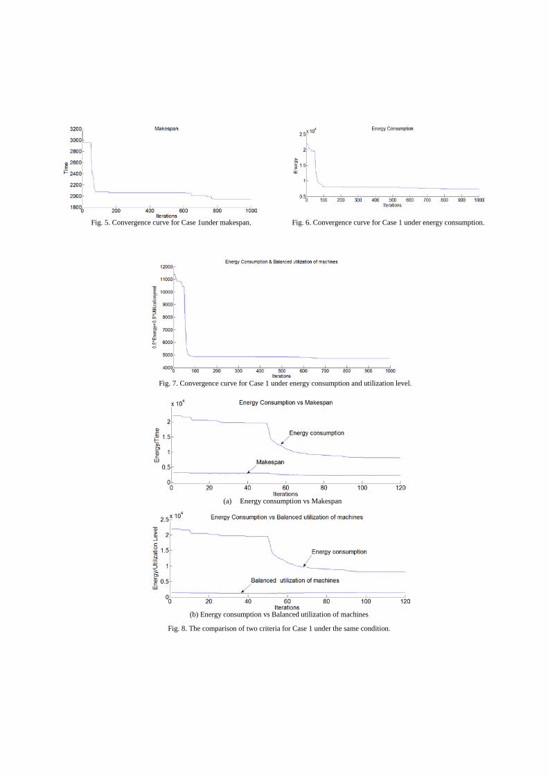
Fig. 5. Convergence curve for Case 1under makespan. Fig. 6. Convergence curve for Case 1 under energy consumption.
Fig. 7. Convergence curve for Case 1 under energy consumption and utilization level.
(a) Energy consumption vs Makespan
(b) Energy consumption vs Balanced utilization of machines
Fig. 8. The comparison of two criteria for Case 1 under the same condition.

Fig. 9. The comparisons of the five algorithms for Case 1 under energy consumption.
Table 1
Comparison studies of five algorithms for case study1 under makespan
HBMO-SA HBMO SA GA ACO Mean 1945.1 2172.7 2147.7 2442.8 2928.5
Maximum 2002.4 2392.8 2317.4 2554.5 3128.2 Minimum 1893.6 1985.1 1980.1 2278.8 2743.7
5.2. Case study 2
The second case study employed another three parts (c.f. Fig. 10) to further validate the proposed approach. The parts have 48 machining features.
The above three conditions in Condition 1 were taken into ac-count again. All the algorithms were conducted for 15 times under these conditions. The optimization results are shown in Fig. 11 and 12. The trend was similar to that in Case study 1. As illustrated in Fig. 13, the similar trend between en-ergy consumption and makespan, energy consump-tion and the balanced utilization of machines were verified again. In addition, through further trials on
other groups of parts, the algorithm was verified to have the stable performance and good optimization results.
The comparisons among the proposed algorithm, HBMO, SA, ACO and GA under condition makespan are shown in Fig. 14. From the results, it can be observed that HBMO converged to a good solution more quickly than other algorithms. The local optima can be avoided by SA. The hybrid HBMO and SA adopted in the approach of this pa-per combined the advantages of HBMO and SA, and thus can achieve better optimized results.
Fig 10. The second group of parts.
Part2-1: Part2-2: Part2-3:
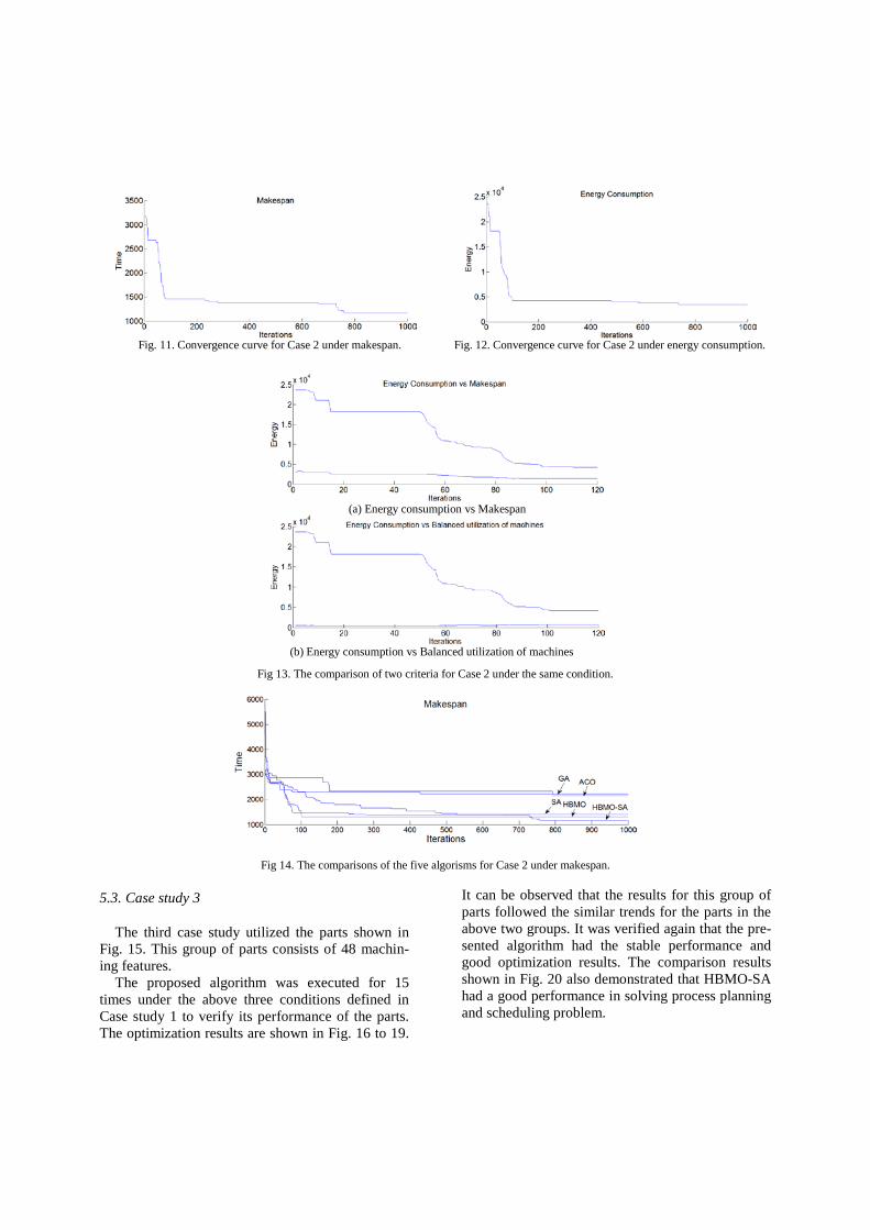
Fig. 11. Convergence curve for Case 2 under makespan. Fig. 12. Convergence curve for Case 2 under energy consumption.
(a) Energy consumption vs Makespan
(b) Energy consumption vs Balanced utilization of machines
Fig 13. The comparison of two criteria for Case 2 under the same condition.
Fig 14. The comparisons of the five algorisms for Case 2 under makespan.
5.3. Case study 3
The third case study utilized the parts shown in Fig. 15. This group of parts consists of 48 machin-ing features.
The proposed algorithm was executed for 15 times under the above three conditions defined in Case study 1 to verify its performance of the parts. The optimization results are shown in Fig. 16 to 19.
It can be observed that the results for this group of parts followed the similar trends for the parts in the above two groups. It was verified again that the pre-sented algorithm had the stable performance and good optimization results. The comparison results shown in Fig. 20 also demonstrated that HBMO-SA had a good performance in solving process planning and scheduling problem.

Fig 15. The third group of parts.
Fig. 16. Convergence curve for Case 3 under makespan. Fig. 17. Convergence curve for Case 3 under energy consumption.
Fig 18. The comparisons of the five algorisms for energy consumption.
(a) Energy consumption vs Makespan
Part3-1: Part3-2: Part3-3: Part3-4:

(b) Energy consumption vs Balanced utilization of machines
Fig 19. The comparison of two criteria for Case 3 under the same condition.
Fig 20. The comparisons of the five algorisms for Case 3 under energy consumption.
6. Conclusions
Sustainable process planning and scheduling are critical to reduce its energy consumption and achieve sustainable development of machining processes. In this paper, sustainable process planning and schedul-ing are explored and presented in a hybrid optimiza-tion approach. In summary, the contributions of the presented approach are from the following aspects: • Systematic models and strategies for dynamic
process planning and scheduling in terms of en-ergy consumption and other important perfor-mance criteria are established. On the basis of the models and strategies, the energy consumption of machining processes is effectively considered to achieve sustainability.
• Compared with some other optimization algo-rithms, the developed HBMO-SA approach can achieve better optimized results. Various cases are used to verify and demonstrate the effective-ness of the approach. The experimental bench-marking demonstrates that the approach is prom-ising and outperforms GA, HBMO and SA. The
approach can be further used to solve other com-plex combinatorial optimization problems.
Future research is intended to be focused on two as-pects. The energy consumption model will be applied in more complex environments involving machine breakdown and existing jobs cancellation. A further test and discussion about hybridization will be done to verify the performance of the presented algorithm.
Acknowledgement
This research was carried out as a part of the Smarter and CAPP-4-SMEs projects which are sup-ported by the 7th European Community Framework Programme under the grant agreement No 610675 (PEOPLE-2013-IAPP-610675) and No 314024 (FP7-2012-NMP-ICT-FoF). The paper reflects only the authors’ views and the Union is not liable for any use that may be made of the information contained therein.

References
[1] H.A. Abbass, Marriage in honey bees optimisation: a haplometrosis polygynous swarming approach, in: Proceedings of the congress on evolutionary computation (2001), 207-214.
[2] H. Adeli, and S.L.Hung, Machine Learning - Neural Networks, Genetic Algorithms, and Fuzzy Sets, John Wiley and Sons, New York, 1995.
[3] H. Adeli, and K. Sarma, Cost Optimization of Structures – Fuzzy Logic, Genetic Algorithms, and Parallel Computing, John Wiley and Sons, West Sussex, United Kingdom, 2006.
[4] V.A. Balogun and P.T. Mativenga, Modelling of direct energy requirements in mechanical machining processes, Journal of Cleaner Production 41(2013), 179-186.
[5] A.A.G. Bruzzonea, D. Anghinolfib, M. Paoluccib, F. Tonellia, Energy-aware scheduling for improving manufacturing process sustainability: A mathematical model for flexible flow shops, CIRP Annals - Manufacturing Technology 61(1) (2012), 459-462.
[6] B. R. Campomanes-Álvareza, O. Cordón, and S. Damas, Evo-lutionary Multi-Objective Optimization for Mesh Simplifica-tion of 3D Open Models, Integrated Computer-Aided Engi-neering 20(4) (2013), 375-390.
[7] P. Curkovic and B. Jerbic, Honey-bees optimization algorithm applied to path planning problem, International Journal of Simulation Modelling 6(3) (2007), 154-164.
[8] N. Diaz, E. Redelsheimer and D. Dornfeld, Energy consump-tion characterization and reduction strategies for milling ma-chine tool use, in: Proceedings of the 18th CIRP international conference on life cycle engineering globalized solutions for sustainability in manufacturing, (2011), 263-267.
[9] J. R. Duflou, K. Kellens, Renaldi, Y. Guo, W. Dewulf, Critical comparison of methods to determine the energy input for dis-crete manufacturing processes, CIRP Annals - Manufacturing Technology, 61(2012), 63–66.
[10] EN 16001: Energy management systems - Requirements with guidance for use, European Standard 2010.
[11] M. Fathian and B. Amiri, A honeybee-mating approach for cluster analysis, International Journal Advanced Manufactur-ing Technology, 38(7-8) (2008), 809-821.
[12] E. Forcael, V. González, F. Orozco, S. Vargas, P. Moscoso, and A. Pantoja, Ant Colony Optimization Model for Tsunamis Evacuation Routes, Computer-Aided Civil and Infrastructure Engineering 29(10) (2014), 723-737.
[13] T. Gutowski, J. Dahmus and A. Thiriez, Electrical Energy Requirements for Manufacturing Processes, in: Proceedings of 13th CIRP International Conference on LCE, (2006).
[14] Y. He, F. Liu, T. Wu, F.P. Zhong and B. Peng, Analysis and estimation of energy consumption for numerical control ma-chining, Proc. Inst. Mech. Eng. Part B J. Eng. Manuf. 226(2) (2012), 255-266.
[15] F. Hejazi, I. Toloue, J. Noorzaei, and M.S. Jaafar, Optimization of Earthquake Energy Dissipation System by Genetic Algo-rithm, Computer-Aided Civil and Infrastructure Engineering, 28(10) (2013), 796-81.
[16] C. Herrmann and S. Thiede, Process chain simulation to foster energy efficiency in manufacturing, CIRP J Manuf Sci Technol 1(4) (2009), 221-229.
[17] W.Y. Hsu, Application of Quantum-behaved Particle Swarm Optimization to Motor Imagery EEG Classification, Interna-tional Journal of Neural Systems, 23(6) (2013), 1350026.
[18] G. Iacca, F. Caraffini, and F. Neri, Multi-strategy Coevolving Aging Particle Optimization, International Journal of Neural Systems, 24(1) (2014), 1450008.
[19] ISO 14040: Environmental management - Life cycle assess-ment - Principles and framework, www.iso.org.
[20] ISO 14044: Environmental management - Life cycle assess-ment - Requirements and guidelines, www.iso.org.
[21] ISO/WD 14955-1 Environmental Evaluation of Machine Tools Part 1: Energy-saving Design Methodology for Machine Tools, International Organization for standardization, Geneva, Swit-zerland.
[22] L. Jia, Y. Wang and L. Fan, Multiobjective bilevel optimization for production-distribution planning problems using hybrid ge-netic algorithm, Integrated Computer-Aided Engineering 21 (2014) 77–90.
[23] M.M. Joly, T. Verstraete and G. Paniagua, Integrated multifi-delity, multidisciplinary evolutionary design optimization of counterrotating compressors, Integrated Computer-Aided Engi-neering 21(3) (2014), 249-261.
[24] F. Jovane, H. Yoshikawab, L. Altingc, C.R. Boërd, E. West-kampere, D. Williamsf, M. Tsengg, G. Seligerh and A.M. Pacii, The incoming global technological and industrial revolution towards competitive sustainable manufacturing, CIRP Annals - Manufacturing Technology 57(2) (2008), 641-659.
[25] S. Kara and W. Li, Unit process energy consumption models for material removal processes, CIRP Annals - Manufacturing Technology 60(1) (2011), 37-40.
[26] S. Kara, S. Manmek and C. Herrmann, Global manufacturing and the embodied energy of products, CIRP Annals - Manufac-turing Technology 59(1) (2010), 29-32.
[27] M. Koudil, K. Benatchba, A. Tarabet and E.B. Sahraoui, Using artificial bees to solve partitioning and scheduling problems in codesign, Applied Mathematics and Computation 186(2) (2007),1710-1722.
[28] L. Li, J. Yan and Z. Xing, Energy requirements evaluation of milling machines based on thermal equilibrium and empirical modeling, Journal of Cleaner Production 52(2013), 113-121.
[29] W. D. Li and C. A. McMahon, A simulated annealing-based optimization approach for integrated process planning and scheduling, International Journal of Computer Integrated Manufacturing 20(1) (2007), 80-95.
[30] W.D. Li, S.K. Ong and A.Y.C. Nee, Optimization of process planning using a constraint-based tabu search method, Interna-tional Journal of Production Research. 42(2004), 1955-1985.
[31] X.X. Li, W.D. Li, X.T. Cai and F.Z. He, A Honey-bee Mating Optimization Approach for Sustainable Manufacturing Process Planning and Scheduling, in: Proceedings of the International Conference on Computer Supported Cooperative Work in De-sign, (2013), 465-470.
[32] D.Y. Lin and Y.H. Ku, Using genetic algorithms to optimize stopping patterns for passenger rail transportation, Computer-Aided Civil and Infrastructure Engineering, 29(4) (2014), 264-278.
[33] J.M. Luna, J.R. Romero, C. Romero and S. Ventura, Reducing Gaps in Quantitative Association Rules: A Genetic Program-ming Free-parameter Algorithm, Integrated Computer-Aided Engineering 21(4) (2014), 321-337.
[34] Y. Marinakis, M. Marinaki and N. Matsatsinis, A hybrid clus-tering algorithm based on honey bees mating optimization and greedy randomized adaptive search procedure. in: Learning and intelligent optimization, Lecture notes in computer science, 5313 (2008), 138-152.
[35] M. Molina-García, J. Calle-Sánchez, C. González-Merino, A. Fernández-Durán and J.I. Alonso, Design of In-Building Wire-less Networks Deployments using Evolutionary Algorithms, In-tegrated Computer-Aided Engineering 21(4) (2014), 367-385.
[36] M. Mori, M. Fujishima, Y. Inamasu and Y. Oda, A study on energy efficiency improvement for machine tools, CIRP Annals - Manufacturing Technology 60 (1) (2011), 145-148.

[37] G. Mouzon and M.B.Yildirim, A framework to minimise total energy consumption and total tardiness on a single machine, In-ternational Journal of Sustainable Engineering 1(2) (2008), 105-116.
[38] S.T. Newman, A. Nassehi, R. Imani-Asrai and V. Dhokia, Energy efficient process planning for CNC machining, CIRP Journal of Manufacturing Science and Technology 5(2012), 127-136.
[39] T. Niknam, S. I. Taheri, J. Aghaei, S. Tabatabaei and M. Nayeripour, A modified honey bee mating optimization algo-rithm for multiobjective placement of renewable energy re-sources, Applied Energy 88(12) (2011), 4817-4830.
[40] E.C. Pedrino, V.O. Roda, E.R.R. Kato, J.H. Saito, M.L. Tronco, R.H. Tsunaki, O. Morandin, and M.C. Nicoletti, A Genetic Programming Based System for the Automatic Construction of Image Filters, Integrated Computer-Aided Engineering 20(3) (2013), 275-287.
[41] D.T. Pham, M. Castellani and A. Ghanbarzadeh, Preliminary design using the bees algorithm. in: Proceedings of eighth in-ternational conference on laser metrology, CMM and machine tool performance, LAMDAMAP, Euspen, Cardiff, UK, (2007), 420-429.
[42] P. Quirós, P. Alonso, I. Díaz, and S. Montes, On the Use of Fuzzy Partitions to Protect Data, Integrated Computer-Aided Engineering 21(4) (2014), 355-366.
[43] O. Reyes, C. Morell and S. Ventura, Evolutionary feature weighting to improve the performance of multi-label lazy algo-rithms, Integrated Computer-Aided Engineering 21(4) (2014), 339-354.
[44] Y. Seow and S. Rahimifard, A framework for modelling energy consumption within manufacturing systems, CIRP Journal of Manufacturing Science and Technology 4(3) (2011), 258-264.
[45] Y. Shafahi, and M. Bagherian, A Customized Particle Swarm Method to Solve Highway Alignment Optimization Problem, Computer-Aided Civil and Infrastructure Engineering 28(1) (2013), 52-67.
[46] N. Siddique and H. Adeli, Computational Intelligence - Syner-gies of Fuzzy Logic, Neural Networks and Evolutionary Com-puting, Wiley, West Sussex, United Kingdom, 2013.
[47] G. Sinden, The contribution of PAS 2050 to the evolution of international greenhouse gas emission standards, The Interna-tional Journal of Life Cycle Assessment 14(2009), 195-203.
[48] H. Tao, J.M. Zain, M.M. Ahmed, A.N. Abdalla, W. Jing, A wavelet-based particle swarm optimization algorithm for digital image watermarking, Integrated Computer-Aided Engineering 19(1) (2012), 81-91.
[49] B. Thomas, Z. Andre and M. Sangkee, Development of an energy consumption monitoring procedure for machine tools, CIRP Annals – Manufacturing Technology 61(2012), 43-46..
[50] N. Weinert, S. Chiotellis and G. Seliger, Methodology for planning and operating energy-efficient production systems, CIRP Annals - Manufacturing Technology 60(1) (2011), 41-44.
[51] X.Y. Wen, X.Y. Li and L. Gao, Honey bees mating optimiza-tion algorithm for process planning problem, Journal of Intelli-gent Manufacturing 25(3) (2012), 459-472.
[52] J.W. Wu, J. C.R. Tseng, and W.N. Tsai, A hybrid linear text segmentation algorithm using hierarchical agglomerative clus-tering and discrete particle swarm optimization, Integrated Computer-Aided Engineering, 21(1) (2014), 35-46.
[53] Z. Zeng, J. Xu, S. Wu and M. Shen, Antithetic Method-based Particle Swarm Optimization for a Queuing Network Problem with Fuzzy Data in Concrete Transportation Systems, Comput-er-Aided Civil and Infrastructure Engineering, 29(10) (2014), 771-800.
[54] X.F. Zhang, S. Y. Zhang, Z. Y. Hu, G. Yu, C. H. Pei and R. N. Sa, Identification of connection units with high GHG emissions
for low-carbon product structure design, Journal of Cleaner Production 27(2011), 118-125.
[55] W. Zhu, H. Hu, and Z. Huang, Calibrating Rail Transit As-signment Models with Genetic Algorithm and Automated Fare Collection Data, Computer-Aided Civil and Infrastructure En-gineering, 29(7) (2014), 518-530.