Embed Size (px)
Citation preview

A HUMAN MOTION CAPTURE SYSTEM BASED ON INERTIAL SENSING AND ACOMPLEMENTARY FILTER
Kan Kanjanapas, Yizhou Wang, Wenlong Zhang,Lauren Whittingham, Masayoshi Tomizuka
Department of Mechanical EngineeringUniversity of California, Berkeley
Berkeley, California 94720Email: {kanjanapas kan, yzhwang, wlzhang,
l.wnittingham, tomizuka}@berkeley.edu
ABSTRACTA human motion capture system is becoming one of the most
useful tools in rehabilitation application because it can recordand reconstruct a patient’s motion accurately for motion analy-sis. In this paper, a human motion capture system is proposedbased on inertial sensing. A microprocessor is implementedon-board to obtain raw sensing data from the inertial measurementunit (IMU), and transmit the raw data to the central process-ing unit. To reject noise in the accelerometer, drift in the gy-roscope, and magnetic distortion in the magnetometer, a time-varying complementary filter (TVCF) is implemented in the cen-tral processing unit to provide accurate attitude estimation. Aforward kinematic model of the human arm is developed to createan animation for patients and physical therapists. Performanceof the hardware and filtering algorithm is verified by experimen-tal results.
INTRODUCTIONThe demand for rehabilitation therapy has rapidly increased
over the years due to an aging population and more patients suf-fering neurological impairments. Currently, rehabilitation ther-apy is provided by physical therapists who observe the patients’joint movement and provide assistance to facilitate their move-ment. Before any rehabilitation treatment, it is very importantto correctly evaluate the patients’ condition so that appropri-ate training plans can be made. Currently physical therapistscan only observe the patients’ joint movement without enoughmeasurement data, so they can only diagnose patients’ symp-tom based on their experience. Moreover, patients’ movement
data cannot be recorded quantitatively for comparison and fur-ther study.
Human motion data is very important in many other fieldsbeyond rehabilitation. Acceleration and velocity data areoftenused to evaluate the performance of athletes [1]. Inertial sensorscan be attached to the trunks and limbs of workers to performan ergonomic evaluation of the workspace [2]. Human motioncapture systems (HMCS) can also provide raw data to performfall detection and prediction for elderly people so that possibleinjuries can be prevented [3].
For the aforementioned purposes, many researchers haveproposed different designs of HMCS, which can be generally cat-egorized into two groups based on their sensor type: the visionsensor based human motion capture system (V-HMCS) and theposition sensor based human motion capture system (P-HMCS).The V-HMCS uses several cameras and reflective markers whichare attached to the subject’s body. By modeling the human bodyas multiple rigid-body segments that form a human skeleton,these cameras can track the motion of each segment in the sametime frame. This allows the reconstruction of human motion inthree-dimensional space. Some examples of V-HMCS includethe VICON and Qualisys motion capture systems [4, 5]. TheP-HMCS uses various types of position sensors such as inertialmeasurement units (IMUs) and encoders. Extended Kalman fil-ter (EKF) [6] and complementary filter [7] can be used to guar-antee the accuracy and precision of the orientation estimation.Encoders can measure the human joint angle and a state estima-tor technique such as kinematic Kalman filter (KKF) could beperformed to find an accurate approximation of joint position.The angular velocity of the limb segment was estimated from the

information of the angular position of the joint and the angularacceleration of the limb. While the angular position of the jointwas measured directly from the encoder, the angular accelera-tion of the limb was indirectly computed by a 2-axis accelerom-eter [8].
Between the two types of HMCS, the V-HMCS providesmore accurate position sensing using multiple high-resolutioncameras. However, these types of cameras are much more ex-pensive than encoders or inertial sensors. Additionally, imageprocessing may not be computationally friendly. Furthermore,since the cameras are fixed, the V-HMCS can only be used in anindoor environment in a limited spatial range. On the contrary,the P-HMCS are cheaper, more compact, and more mobile thanV-HMCS. The signal processing is also simpler for the P-HMCS.Moreover, most of the P-HMCS are configurable and more func-tions can be customized. For example, wireless modules can beadded to an IMU so that all signals can be transmitted withoutcommunication wires [9]. In the rehabilitation application, weneed to measure the joint angle information for neuromusculardisease diagnosis and health monitoring. Although the measure-ment from some P-HMCS (for example, IMUs) are less accuratethan that of V-HMCS, they still provide enough precision forre-habilitation application.
Inertial sensing is a common method used by P-HMCS, andmany scholars have researched how to acquire accurate kine-matic estimation [10–12]. However, most of the previous re-search focused on filtering algorithm design, but few researchersdiscussed how to calibrate the inertial sensors effectively.
In this paper, an upper-extremity motion capture system isproposed based on inertial sensing. An IMU is used to obtainraw sensing data of triaxial acceleration, angular velocity, andmagnetic field. Hardware design for sensor alignment is pro-posed to guarantee the tight attachment of the sensors. To rejectthe noise in accelerometers, drift in gyroscopes, and magneticdistortion in magnetometers, a time-varying complimentary fil-ter (TVCF) is employed to provide accurate rotation estimationand its performance is compared with other algorithms. Anima-tions are created based on forward kinematics of the upper arm.Experimental results are shown to demonstrate the performanceof the proposed hardware design and filtering algorithm.
The remainder of the paper is organized as follows. Sec-tion II introduces several methods describing rotation kinemat-ics. Section III details the forward kinematics used for humanmotion animation. IMU sensor attachment and calibration arediscussed in Section IV. The TVCF algorithm is introduced and itis compared with the TRIAD algorithm and the gyro integrationalgorithm in Section V. Section VI gives the experimental resultsand animation results are compared with the video record. Weconclude this paper and propose future work in Section VII.
ROTATION KINEMATICSEuler’s fundamental theorem on rotation states that a rota-
tion RRR can be defined by an angle of rotationφ and an axis of
rotationrrr [13]. A rotation tensor can be expressed, using nota-tion introduced by Gibbs, as
RRR= LLL(φ , rrr) = cos(φ)(III − rrr ⊗ rrr)− sin(φ)(εεεrrr)+ rrr ⊗ rrr (1)
whereIII andεεε are the identity tensor and the alternator respec-tively. If right-handed basis vectors{ppp1, ppp2, ppp3} are chosen forthe reference frameΨr , and these vectors are transformed to theset{ttt1, ttt2, ttt3}, which are the basis vectors for the body frameΨb,by a rotation, then the rotation can be expressed as the followingsecond-order tensor,
RRR=3
∑i=1
3
∑k=1
Rikttt i ⊗ tttk =3
∑i=1
3
∑k=1
Rik pppi ⊗ pppk =3
∑i=1
ttt i ⊗ pppi (2)
whereRik = tttk · pppi . Considering a free vectorrrr expressed withrespect to both sets of basis vectors as:rrr = r1ppp1+ r2ppp2+ r3ppp3 =b1ttt1 + b2ttt2 + b3ttt3, The two coordinate vectors can be relatedusing a rotation matrixAAA as
bbb= AAArrr (3)
wherebbb = [b1 b2 b3]T , rrr = [r1 r2 r3]
T , andAki = Rik for i,k ∈{1,2,3}. The rotation matrix,A ∈ SO(3) (special orthogonalgroup) is subject to a unity determinant constraint, detA = 1, be-cause it is a non-minimal non-singular attitude parameterization.Its kinematic equation can be derived as,
AAA=−[ωωω×]AAA (4)
where the cross product matrix of the angular velocity ofΨb withrespect toΨr expressed in the body frame,ωωω = [ω1,ω2,ω3]
T , isgiven by
[ωωω×] =
0 −ω3 ω2
ω3 0 −ω1
−ω2 ω1 0
(5)
Another useful mathematical tool for parameterizing atti-tude is the quaternion. A quaternion, which requires the leastnumber of variables among non-singular parameterizations, isalso defined by a rotation axisrrr and a rotation angleφ ,
qqq=
[
qqqv
q4
]
=
[
rrr sin(φ/2)
cos(φ/2)
]
(6)
In addition, letqqqA be the quaternion of bodyA orientation andqqqBbe the quaternion of bodyB orientation respectively. The relative
quaternion of bodyB with respect to bodyA is given by [14],
qqqrelB w.r.t A = qqqB
⊗
qqq−1A
=[
Ξ(qqq−1A ) qqq−1
A
]
qqqB (7)
where
Ξ(qqq) =
[
q4I3×3+[qqqv×]
−qqqTv
]
and qqq−1 =
[
−qqqv
q4
]
(8)
Euler angles are defined by decomposing a rotation into threerelatively simpler rotations,
AAA=
1 0 0
0 cosφ sinφ0 −sinφ cosφ
cosθ 0 −sinθ0 1 0
sinθ 0 cosθ
cosψ sinψ 0
−sinψ cosψ 0
0 0 1
(9)Here, the 3-2-1 set of Euler angles are adopted. The Euler anglesare extensively used because in this form the rotation becomeseasy to visualize.
FORWARD KINEMATICSHuman Upper Extremity Model
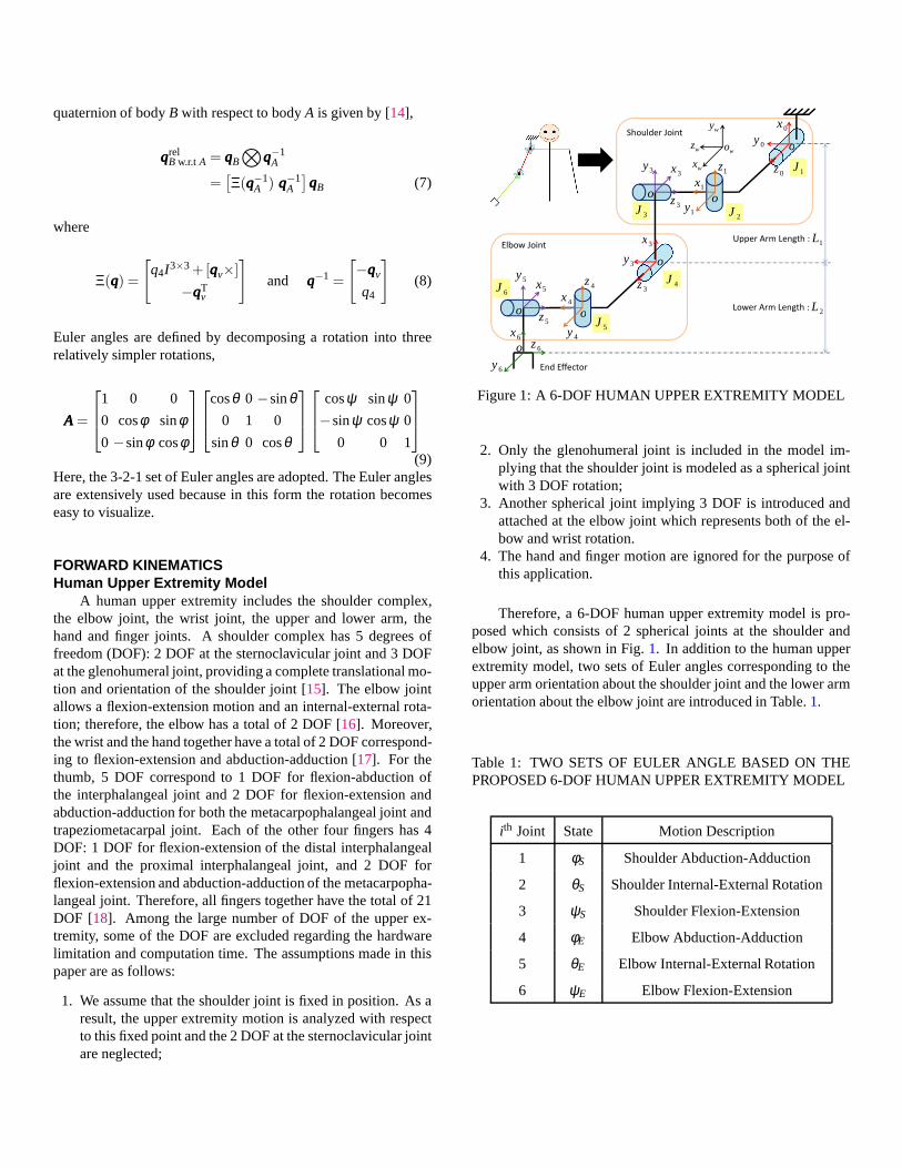
A human upper extremity includes the shoulder complex,the elbow joint, the wrist joint, the upper and lower arm, thehand and finger joints. A shoulder complex has 5 degrees offreedom (DOF): 2 DOF at the sternoclavicular joint and 3 DOFat the glenohumeral joint, providing a complete translational mo-tion and orientation of the shoulder joint [15]. The elbow jointallows a flexion-extension motion and an internal-externalrota-tion; therefore, the elbow has a total of 2 DOF [16]. Moreover,the wrist and the hand together have a total of 2 DOF correspond-ing to flexion-extension and abduction-adduction [17]. For thethumb, 5 DOF correspond to 1 DOF for flexion-abduction ofthe interphalangeal joint and 2 DOF for flexion-extension andabduction-adduction for both the metacarpophalangeal joint andtrapeziometacarpal joint. Each of the other four fingers has4DOF: 1 DOF for flexion-extension of the distal interphalangealjoint and the proximal interphalangeal joint, and 2 DOF forflexion-extension and abduction-adduction of the metacarpopha-langeal joint. Therefore, all fingers together have the total of 21DOF [18]. Among the large number of DOF of the upper ex-tremity, some of the DOF are excluded regarding the hardwarelimitation and computation time. The assumptions made in thispaper are as follows:
1. We assume that the shoulder joint is fixed in position. As aresult, the upper extremity motion is analyzed with respectto this fixed point and the 2 DOF at the sternoclavicular jointare neglected;
0x
0y
0z1z
1x
1y
o
oo3z
3x3y
x L
�����������
������������ ��
1J
2J3J
wx
wz
wy
wo
o
oo
o
4z
4x
4y5z
5x5y
3x
3y
3z
6x
6y
6z
1L
2L
��������
�������� ��
������������ ��
������������ ��
4J
5J
6J
Figure 1: A 6-DOF HUMAN UPPER EXTREMITY MODEL
2. Only the glenohumeral joint is included in the model im-plying that the shoulder joint is modeled as a spherical jointwith 3 DOF rotation;
3. Another spherical joint implying 3 DOF is introduced andattached at the elbow joint which represents both of the el-bow and wrist rotation.
4. The hand and finger motion are ignored for the purpose ofthis application.
Therefore, a 6-DOF human upper extremity model is pro-posed which consists of 2 spherical joints at the shoulder andelbow joint, as shown in Fig.1. In addition to the human upperextremity model, two sets of Euler angles corresponding to theupper arm orientation about the shoulder joint and the lowerarmorientation about the elbow joint are introduced in Table.1.
Table 1: TWO SETS OF EULER ANGLE BASED ON THEPROPOSED 6-DOF HUMAN UPPER EXTREMITY MODEL
ith Joint State Motion Description
1 φS Shoulder Abduction-Adduction
2 θS Shoulder Internal-External Rotation
3 ψS Shoulder Flexion-Extension
4 φE Elbow Abduction-Adduction
5 θE Elbow Internal-External Rotation
6 ψE Elbow Flexion-Extension

Forward Kinematic FormulationTo generate a forward kinematic model of the human upper
extremity motion, several coordinate systems that describe thepositions of the elbow and wrist joints are introduced in Fig. 2.
A global frame,ΨE, is defined for determining the absoluteposition and the orientation of both upper and lower arms. Wedefine the body frames,ΨB,1 andΨB,2 rigidly attached to the up-per and lower arms respectively, coincide with the global framewhen the arm is in the straight down position. Based on thiscoordinate system, the abduction-adduction motion is the rota-tion along theEEEx direction. The internal-external rotation occursalong theEEEy direction and the flexion-extension occurs along theEEEz direction. If the Euler anglesψS,θS,φS are estimated, then theelbow position expressed in the global frame can be written as,
rrrΨEElbow = RRRE
B,1 (ψS,θS,φS) rrrΨB,1Elbow (10)
RRREB,1(ψS,θS,φS) = RRRZ (ψS)RRRY (θS)RRRX (φS)
=
cosψS −sinψS 0
sinψS cosψS 0
0 0 1
cosθS 0 sinθS
0 1 0
−sinθS 0 cosθS
1 0 0
0 cosφS −sinφS
0 sinφS cosφS
(11)
whererrrΨB,1Elbow is the elbow position with respect to the body frame
ΨB,1. Similarly, if the Euler anglesψE,θE,φE are obtained, thewrist position is given by
rrrΨEWrist = rrrΨE
Elbow+RRREB,1(ψS,θS,φS)RRR
B,1B,2(ψE,θE,φE)rrr
ΨB,2Wrist (12)
whererrrΨB,2Wrist is the wrist position with respect to the body frame
ΨB,2.
SYSTEM OVERVIEWIn this section, the hardware design and software implemen-
tation of the inertial sensing system are introduced.The proposed upper extremity motion capture system in-
cludes two onboard sensing units and a central processing unit.Fig. 3(a) shows one onboard sensing unit, which includes a9-DOF IMU sensor stick (the ADXL345 accelerometer, theHMC5883 magnetometer, and the ITG-3200 gyroscope) and anArduino Pro Mini microprocessor with 8MHz processing rate.The Arduino processor requests sensing data from the IMU every10 milliseconds (sampling rate is 100Hz) and transmits the rawdata to the central processing unit via a serial port. A desktopcomputer is employed as the central processing unit, and Lab-VIEW is used to read the raw sensing data from serial ports.
It is very important to guarantee tight attachment of the sens-ing unit to human arm so that there is minimum relative motion
yb
yE
zE
xE
,1yszb
xb
ΕΨ
BΨ
,1zs′
Ψ
yb′
yb′zb′
,1zs
,1xs 1,SΨ
,2xs,2zs
,2ys
2,SΨ,2xs′
,2ys′,2zs′,1xs′ ,1ys′
1,S′Ψ
2,S′Ψ
Figure 2: DEFINITION OF COORDINATE SYSTEM ATEACH JOINT FOR FORWARD KINEMATICS FORMULA-TION
Figure 3: (a) THE SENSING UNIT (b) A QUANSER 3-DOFGYROSCOPE (c) TWO SENSING UNITS ATTACHED TOORTHOSES
between the sensors and human arm. A simple solution seemsto be direct attachment with velcro [11,19], but this method can-not guarantee firm attachment. To solve this problem, we put anorthosis on the subject’s arm and firmly attach a sensor-orthosislocking mechanism as shown in Fig.3(c).

Sensor CalibrationThe accuracy of any attitude estimation algorithm is signif-
icantly dependent on the quality of sensor calibration. Theac-celerometer calibration is relatively easy because the magnitudeand the direction of gravity are known, and it can serve as theground truth. The gyroscope calibration utilizes the Quanser 3-DOF gyroscope, of which each gimbal is equipped with a 5000lines per revolution quadrature optical encoder providingthe trueangular velocity.
The calibration of magnetometers is the most challengingdue to the complexity of its measurement model and the lackof true reference for the local magnetic field. In this paper,themethodology proposed by Foster et.al. [20] is adopted. Thismethod does not require an external reference if only the relativeintensity of the magnetic field is of interest. The gains, offsetsand non-orthogonality angles are estimated using least squares.
FILTER DESIGNAttitude Determination From Vector Measurement
In order to calculate the relative orientation of the sensorframe to the body frame, we are seeking an attitude determina-tion algorithm which provides an accurate attitude estimate uti-lizing the available inertial sensor measurements. Among manyalgorithms present in literature, the TRIAD algorithm [21] iswell suited for our application due to its simplicity.
The TRIAD algorithm provides a deterministic solution forthe attitude parameterized by a rotation matrix. We denote thevector measured inΨb asbi and the one measured inΨr asri .A rotation relating those vectors may not exist in general due tosensor noises. Instead, two triadsW = {w1,w2,w3} andV ={v1,v2,v3} can be constructed deterministically from the vectormeasurements. The rotation matrixA, which is the estimate ofthe relative orientation of the two frames, can be computed bythe two triads as,
A =3
∑i=1
wivTi (13)
For the human motion capture application, the two vector mea-surements are taken as the normalized gravitational vectorandthe normalized magnetic flux. We therefore obtain the con-stant frame misalignment between the inertial sensors and thehuman body. When the human body is in motion, the accuracyof the TRIAD algorithm is inhibited due to the fact that the ac-celerometer also measures motion accelerations and the environ-mental magnetic field is space-varying. Hence, the time-varyingcomplementary pre-filter is motivated to: (a) attenuate thehigh-frequency noise in the vector measurements; (b) attenuate thelow-frequency bias in the rate measurement; (c) identify pos-sible motion accelerations and distortions in the environmentalmagnetic field.
(a)
acc
gyro
mag
gyro
(b)
Figure 4: (a) DETAILS OF THE TVCF BLOCK (b) THE NON-LINEAR COMPLEMENTARY FILTER AS A PREFILTER TOTHE TRIAD METHOD USED IN 3-DOF ATTITUDE ESTI-MATION
Time-varying complementary filter for sensor frame at-titude estimation
Since rate (gyroscopes) and angle (accelerometers andmagnetometers) sensors possess noises in different frequencyregimes, a complementary filtering method can be utilized toproduce a more accurate attitude estimation. Wang et al. [22]proposed the following complementary filter providing the esti-mate of the vector measurements in the sensor frame. The blockdiagram is shown in Fig.4. The high-frequency noises, presentin the accelerometer and magnetometer measurements, are atten-uated by the low-pass filters in the algorithm. Consequently, lessoscillatory behavior is observed in the attitude estimation. It canalso be shown that the bias present in the gyroscope measure-ment will not accumulate for long term operation, due to the factthat the angle measurements are incorporated. The discrete-timecomplementary filter equation is given as,
bi(k+1) =ωci(k+1)∆t
2+ωci(k+1)∆t(bi(k)+bi(k+1))+
2−ωci(k+1)∆t2+ωci(k+1)∆t
bi(k)+∆t
2+ωci(k+1)∆t(bgi(k)+ bgi(k+1))
i = 1,2(14)

75 80 85 90 95 100 105 110 115 120−0.5
0
0.5
q1
Encoder TVCF+TRIAD Rate integration TRIAD
75 80 85 90 95 100 105 110 115 120−0.5
0
0.5
q2
75 80 85 90 95 100 105 110 115 120−0.5
0
0.5
q3
75 80 85 90 95 100 105 110 115 120
2
4
ωc,a
cc
75 80 85 90 95 100 105 110 115 120
2
4
ωc,m
ag
time(sec)
(a)
100 101 102 103 104 105 106 107 108 109 110
−0.5
−0.4
−0.3
−0.2
−0.1
0
0.1
magnetic distortion
gyroscope drift
(b)
Figure 5: (a) PLOT OF THE ATTITUDE ESTIMATES FROMTHE DIFFERENT METHODS AND THE TRANSITIONS OFTHE FUZZY LOGIC BASED CUTOFF FREQUENCIES. (b)ZOOMED-IN PLOT OFq1
wherebgi(k) = A(k)ri and the gravity vector expressed in theglobal frameΨE is constant. In addition,bgi(k) is given by
bgi(k) = A(k)ri
=−[ωωω(k)×]A(k)ri
≈−[ωωω(k)×]bi(k), i = 1,2
(15)
Note that∆t denotes the sampling period,ωci is a fuzzy-logicbased time-varying filter cutoff frequency,b1 and b2 representthe best estimate of the gravity vector and the magnetic flux ex-pressed with respect to the sensor frame. The attitude estimate attime stepk+1, parameterized by the rotation matrixA, is thencalculated by the TRIAD algorithm. Chang-Siu et al. [23] pro-posed a fuzzy logic to take advantage of the physical propertiesof the accelerometer and the magnetometer, to adapt the cutofffrequencies. By varying the cutoff frequency, the filter canadjusttrustworthiness between the rate sensors and the angle sensors.The fuzzy logic is based on the intuition that the angle sensorsshould be contemned when the magnitude of the accelerometer
(a)
22 22.5 23 23.5 24 24.5 25 25.5 26
0
0.2
0.4
0.6
0.8
1
Time (s)
Lo
we
rArm
w.r
.t U
pp
erA
rm
(b)
Figure 6: (a) UPPER AND LOWER ARM ROTATION ANDRELATIVE QUATERNION (b) ZOOMED-IN PLOT OF REL-ATIVE QUATERNION
or magnetometer signals deviate from their initial value (indicat-ing rotational or translational acceleration, and magnetic distur-bances), and valued when these signals are close to their initialvalues.
EXPERIMENTAL RESULTSComparison with Gyro setup
The accuracy of the sensor frame attitude estimation is eval-uated with the Quanser 3-DOF gyroscope shown in Fig.3b. TheIMU undergoes a random rotational motion when it is rigidly at-

tached to the Quanser setup. The reference attitude is measuredby the 5000 lines/rev quadrature optical encoders on each gim-bal. The encoder angles are then converted to the quaternionparameterization which provides the true reference. Magneticshielding is applied to motors on the testbed to minimize thechange of magnetic field due to gimbal movements. However,the magnetic distortion is still large enough to cause problems ifthe TVCF is not applied. All attitude estimates from the IMUare processed in real time and the quaternions are transmittedto the computer. Fig.5a compares the first three componentsof the quaternions from the encoders, the TVCF+TRIAD algo-rithm, the rate integration method and the sole TRIAD method.The upper and lower limits of the cutoff frequency are 5rad/sand 0.1rad/s. It can easily be observed that (i) in theq1 plot, therate integration drifts in 2 minutes of operation, (ii) in the timeintervals where the fuzzy logic shifts the cutoff frequencyto itslower limit in the magnetometer channel, the TRIAD methodgives inaccurate estimates due to the change of magnetic field (ataround 103s and 107s). The estimate from the proposed algo-rithm gives the most accurate attitude estimates among the threemethods.
Calibration for Sensor Frame MisalignmentThe experiment was conducted with a healthy 25 year-old
male subject with normal upper extremity motion. The sensorcalibration was performed using the calibration methodology in-troduced in Section 4. The vector measurements, namely thegravity vectorrrr1 and the magnetic fluxrrr2, were taken in theglobal frame and recorded. The IMU sensors were rigidly at-tached to the upper arm and lower arm orthoses. In the motioncapture experiment, the subject wore the orthoses at his rightarm which was initially in the straight down posture. We as-sumed that the body frames coincided with the global frame dur-ing those periods of time. The vector measurements with re-spect to the sensor framesbbb1 andbbb2 were recorded. Utilizing theTRIAD method, the misalignment orientation from the sensorframes to the body frame can be obtained. Therefore, the vec-tor measurements and the angular velocity vector can be writtenwith respect to the body frames. With this information, the bodyframe orientation can be estimated using the TVCF method.
Body Frames OrientationThe subject moved his upper limb following the pre-defined
motion patterns including two cycles of 0◦ − 90◦ − 0◦ shoul-der abduction-adduction, shoulder flexion-extension and elbowinternal-external rotation. At the same time, these motions werealso recorded by a video camera for forward kinematic verifica-tion.
Fig. 6a shows the quaternion profiles of the upper and thelower arms orientation, and the relative quaternion profilebe-tween these two arms. Note that these quaternions are obtainedby different estimation algorithms; gyro integration, TRIAD andTVCF. In addition,q1,q2 andq3 represent abduction-adduction,
0 10 20−50
0
50
100
Time [s]
Upp
erA
rm Y
aw [d
eg]
Shoulder Flex/Ext (Z)
0 10 20−20
0
20
40
60
Time [s]
Upp
erA
rm P
itch
[deg
]
Shoulder Int/Ext Rot (Y)
0 10 20−100
−50
0
50
Time [s]
Upp
erA
rm R
ow [d
eg]
Shoulder Ab/Add (X)
0 10 20−100
−50
0
50
Time [s]
Low
erA
rm Y
aw [d
eg]
Elbow Flex/Ext (Z)
0 10 20−50
0
50
100
Time [s]
Low
erA
rm P
itch
[deg
]
Elbow Int/Ext Rot (Y)
0 10 20−100
−50
0
50
Time [s]
Low
erA
rm R
ow [d
eg]
Elbow Ab/Add (X)
TRIADgyroTVCF
Figure 7: EULER ANGLE OF UPPER AND LOWER ARMORIENTATION
internal-external rotation, and flexion-extension with respect tothe global frame. The first two dominant cycles ofq1 imply two0◦−90◦−0◦ shoulder abduction-adduction motion. This impli-cation is also the same forq2 andq3. During shoulder abduction-adduction and shoulder flexion-extension, the lower arm rarelyrotated relative to the upper arm. Therefore, the upper and lowerarm quaternions are close, and the relative quaternion betweenlower arm and upper arm is close to the identity quaternion.However, in the last motion pattern, the lower arm internally-externally rotated larger than the upper arm significantly.Thisphenomena can be seen from the last plot in Fig.6a, in which therelative quaternionq2 is dominant in the last two cycles due tothe elbow internal-external rotation.
The relative quaternion figure is zoomed in and shown inFig.6b. It can be seen that The TRIAD without TVCF algorithmgives the good attitude estimation when the arm motion is slow(ex. 22.5s - 23.0s). However, when the arm motion is fast, thegyro integration provides reasonable estimation result (ex. 23.5s- 24.0s). The TRIAD together with the TVCF algorithm is de-ployed to get the best attitude estimation result.
Euler Angle Conversion ResultsThe experimental results of Euler angle conversion are
shown in Fig.7.During the first motion pattern, the experimental result
shows 0◦−90◦−0◦ shoulder abduction-adduction pattern (roll).
������� ��������� ��������
��������� ���������
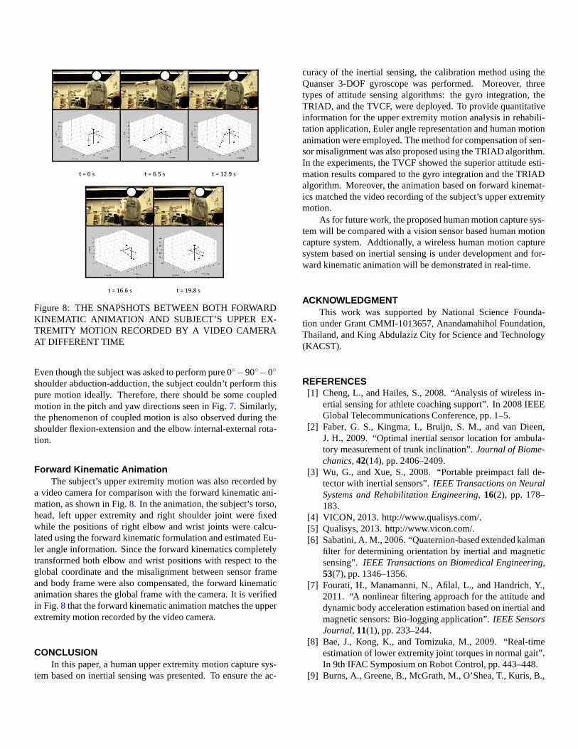
Figure 8: THE SNAPSHOTS BETWEEN BOTH FORWARDKINEMATIC ANIMATION AND SUBJECT’S UPPER EX-TREMITY MOTION RECORDED BY A VIDEO CAMERAAT DIFFERENT TIME
Even though the subject was asked to perform pure 0◦−90◦−0◦
shoulder abduction-adduction, the subject couldn’t perform thispure motion ideally. Therefore, there should be some coupledmotion in the pitch and yaw directions seen in Fig.7. Similarly,the phenomenon of coupled motion is also observed during theshoulder flexion-extension and the elbow internal-external rota-tion.
Forward Kinematic AnimationThe subject’s upper extremity motion was also recorded by
a video camera for comparison with the forward kinematic ani-mation, as shown in Fig.8. In the animation, the subject’s torso,head, left upper extremity and right shoulder joint were fixedwhile the positions of right elbow and wrist joints were calcu-lated using the forward kinematic formulation and estimated Eu-ler angle information. Since the forward kinematics completelytransformed both elbow and wrist positions with respect to theglobal coordinate and the misalignment between sensor frameand body frame were also compensated, the forward kinematicanimation shares the global frame with the camera. It is verifiedin Fig.8 that the forward kinematic animation matches the upperextremity motion recorded by the video camera.
CONCLUSIONIn this paper, a human upper extremity motion capture sys-
tem based on inertial sensing was presented. To ensure the ac-
curacy of the inertial sensing, the calibration method using theQuanser 3-DOF gyroscope was performed. Moreover, threetypes of attitude sensing algorithms: the gyro integration, theTRIAD, and the TVCF, were deployed. To provide quantitativeinformation for the upper extremity motion analysis in rehabili-tation application, Euler angle representation and human motionanimation were employed. The method for compensation of sen-sor misalignment was also proposed using the TRIAD algorithm.In the experiments, the TVCF showed the superior attitude esti-mation results compared to the gyro integration and the TRIADalgorithm. Moreover, the animation based on forward kinemat-ics matched the video recording of the subject’s upper extremitymotion.
As for future work, the proposed human motion capture sys-tem will be compared with a vision sensor based human motioncapture system. Addtionally, a wireless human motion capturesystem based on inertial sensing is under development and for-ward kinematic animation will be demonstrated in real-time.
ACKNOWLEDGMENTThis work was supported by National Science Founda-
tion under Grant CMMI-1013657, Anandamahihol Foundation,Thailand, and King Abdulaziz City for Science and Technology(KACST).
REFERENCES[1] Cheng, L., and Hailes, S., 2008. “Analysis of wireless in-
ertial sensing for athlete coaching support”. In 2008 IEEEGlobal Telecommunications Conference, pp. 1–5.
[2] Faber, G. S., Kingma, I., Bruijn, S. M., and van Dieen,J. H., 2009. “Optimal inertial sensor location for ambula-tory measurement of trunk inclination”.Journal of Biome-chanics,42(14), pp. 2406–2409.
[3] Wu, G., and Xue, S., 2008. “Portable preimpact fall de-tector with inertial sensors”.IEEE Transactions on NeuralSystems and Rehabilitation Engineering,16(2), pp. 178–183.
[4] VICON, 2013. http://www.qualisys.com/.[5] Qualisys, 2013. http://www.vicon.com/.[6] Sabatini, A. M., 2006. “Quaternion-based extended kalman
filter for determining orientation by inertial and magneticsensing”. IEEE Transactions on Biomedical Engineering,53(7), pp. 1346–1356.
[7] Fourati, H., Manamanni, N., Afilal, L., and Handrich, Y.,2011. “A nonlinear filtering approach for the attitude anddynamic body acceleration estimation based on inertial andmagnetic sensors: Bio-logging application”.IEEE SensorsJournal,11(1), pp. 233–244.
[8] Bae, J., Kong, K., and Tomizuka, M., 2009. “Real-timeestimation of lower extremity joint torques in normal gait”.In 9th IFAC Symposium on Robot Control, pp. 443–448.
[9] Burns, A., Greene, B., McGrath, M., O’Shea, T., Kuris, B.,
Ayer, S., Stroiescu, F., and Cionca, V., 2010. “ShimmerTM
- a wireless sensor platform for noninvasive biomedical re-search”.IEEE Sensors Journal,10(9), pp. 1527–1534.
[10] Kubelka, V., and Reinstein, M., 2012. “Complementaryfiltering approach to orientation estimation using inertialsensors only”. In 2012 IEEE International Conference onRobotics and Automation (ICRA), pp. 599 –605.
[11] Sabatini, A., 2006. “Quaternion-based extended kalmanfilter for determining orientation by inertial and magneticsensing”. IEEE Transactions on Biomedical Engineering,53(7), pp. 1346–1356.
[12] Mahony, R., Hamel, T., and Pflimlin, J.-M., 2008. “Nonlin-ear complementary filters on the special orthogonal group”.IEEE Transactions on Automatic Control,53(5), pp. 1203–1218.
[13] O’Reilly, O. M., 2008. Intermediate dynamics for engi-neers: a unified treatment of Newton-Euler and Lagrangianmechanics. Cambridge University Press.
[14] Crassidis, J. L., and Junkins, J. L., 2011.Optimal estima-tion of dynamic systems, Vol. 24. Chapman & Hall.
[15] Ball, S. J., Brown, I. E., and Scott, S. H., 2007. “Medarm: arehabilitation robot with 5dof at the shoulder complex”. In2007 IEEE/ASME International Conference on AdvancedIntelligent Mechatronics, pp. 1–6.
[16] Klopcar, N., and Lenarcic, J., 2005. “Kinematic model fordetermination of human arm reachable workspace”.Mec-canica,40(2), pp. 203–219.
[17] Prokopenko, R., Frolov, A., Biryukova, E., and Roby-Brami, A., 2001. “Assessment of the accuracy of a hu-man arm model with seven degrees of freedom”.Journalof Biomechanics,34(2), pp. 177–185.
[18] ElKoura, G., and Singh, K., 2003. “Handrix: animatingthe human hand”. In 2003 ACM SIGGRAPH/EurographicsSymposium on Computer Animation, pp. 110–119.
[19] von Buren, T., Mitcheson, P., Green, T., Yeatman, E.,Holmes, A., and Troster, G., 2006. “Optimization of in-ertial micropower generators for human walking motion”.IEEE Sensors Journal,6(1), pp. 28–38.
[20] Foster, C., and Elkaim, G., 2008. “Extension of a two-stepcalibration methodology to include nonorthogonal sensoraxes”. IEEE Transactions on Aerospace and ElectronicSystems,44(3), pp. 1070–1078.
[21] Shuster, M. D., and Oh, S. D., 1981. “Three-axis attitudedetermination from vector observations”.AIAA Journal ofGuidance and Control,4(1), pp. 70–77.
[22] Wang, Y., Chang-Siu, E., Brown, M., Tomizuka, M., Al-majed, M., and Alsuwaidanan, B., 2012. “Three dimen-sional attitude estimation via the triad algorithm and a time-varying complementary filter”. In 2012 ASME DynamicSystems and Control Conference (DSCC), pp. 2082–2090.
[23] Chang-Siu, E., Tomizuka, M., and Kong, K., 2011. “Time-varying complementary filtering for attitude estimation”.In 2011 IEEE/RSJ International Conference on IntelligentRobots and Systems (IROS), IEEE, pp. 2474–2480.