Embed Size (px)
Citation preview
Lee S. Mason and Jeffrey G. Schreiber
Glenn Research Center, Cleveland, Ohio
A Historical Review of Brayton and Stirling PowerConversion Technologies for Space Applications
NASA/TM—2007-214976
November 2007
Paper 2034
https://ntrs.nasa.gov/search.jsp?R=20070038168 2018-06-17T23:47:35+00:00Z
NASA STI Program . . . in Profile
Since its founding, NASA has been dedicated to the
advancement of aeronautics and space science. The
NASA Scientific and Technical Information (STI)
program plays a key part in helping NASA maintain
this important role.
The NASA STI Program operates under the auspices
of the Agency Chief Information Officer. It collects,
organizes, provides for archiving, and disseminates
NASA’s STI. The NASA STI program provides access
to the NASA Aeronautics and Space Database and its
public interface, the NASA Technical Reports Server,
thus providing one of the largest collections of
aeronautical and space science STI in the world.
Results are published in both non-NASA channels and
by NASA in the NASA STI Report Series, which
includes the following report types:
• TECHNICAL PUBLICATION. Reports of
completed research or a major significant phase
of research that present the results of NASA
programs and include extensive data or theoretical
analysis. Includes compilations of significant
scientific and technical data and information
deemed to be of continuing reference value.
NASA counterpart of peer-reviewed formal
professional papers but has less stringent
limitations on manuscript length and extent of
graphic presentations.
• TECHNICAL MEMORANDUM. Scientific
and technical findings that are preliminary or
of specialized interest, e.g., quick release
reports, working papers, and bibliographies that
contain minimal annotation. Does not contain
extensive analysis.
• CONTRACTOR REPORT. Scientific and
technical findings by NASA-sponsored
contractors and grantees.
• CONFERENCE PUBLICATION. Collected
papers from scientific and technical
conferences, symposia, seminars, or other
meetings sponsored or cosponsored by NASA.
• SPECIAL PUBLICATION. Scientific,
technical, or historical information from
NASA programs, projects, and missions, often
concerned with subjects having substantial
public interest.
• TECHNICAL TRANSLATION. English-
language translations of foreign scientific and
technical material pertinent to NASA’s mission.
Specialized services also include creating custom
thesauri, building customized databases, organizing
and publishing research results.
For more information about the NASA STI
program, see the following:
• Access the NASA STI program home page at
http://www.sti.nasa.gov
• E-mail your question via the Internet to
• Fax your question to the NASA STI Help Desk
at 301–621–0134
• Telephone the NASA STI Help Desk at
301–621–0390
• Write to:
NASA Center for AeroSpace Information (CASI)
7115 Standard Drive
Hanover, MD 21076–1320
National Aeronautics and
Space Administration
Glenn Research Center
Cleveland, Ohio 44135
Prepared for the
Space Nuclear Conference 2007
sponsored by the American Nuclear Society
Boston, Massachusetts, June 24–28 2007
Paper 2034
Lee S. Mason and Jeffrey G. Schreiber
Glenn Research Center, Cleveland, Ohio
A Historical Review of Brayton and Stirling PowerConversion Technologies for Space Applications
NASA/TM—2007-214976
November 2007
Acknowledgments
The information discussed here was compiled for NASA with support from the Science Mission Directorate and Exploration
Systems Mission Directorate. The authors wish to acknowledge the contributions of Richard Shaltens
and Lanny Thieme who provided valuable input.
Available from
NASA Center for Aerospace Information
7115 Standard Drive
Hanover, MD 21076–1320
National Technical Information Service
5285 Port Royal Road
Springfield, VA 22161
Available electronically at http://gltrs.grc.nasa.gov
Level of Review: This material has been technically reviewed by technical management.
This report contains preliminary findings,
subject to revision as analysis proceeds.
NASA/TM—2007-214976 1
A Historical Review of Brayton and Stirling Power Conversion Technologies for Space Applications
Lee S. Mason and Jeffrey G. Schreiber
National Aeronautics and Space Administration Glenn Research Center Cleveland, Ohio 44135
Abstract
Dynamic power conversion technologies, such as closed Brayton and free-piston Stirling, offer many advantages for space power applications including high efficiency, long life, and attractive scaling characteristics. This paper presents a historical review of Brayton and Stirling power conversion technology for space and discusses on-going development activities in order to illustrate current technology readiness. The paper also presents a forecast of potential future space uses of these power technologies.
I. Introduction The main advantages of dynamic power conversion sys-
tems for space power are high efficiency, long life, and scalability to high power.
Efficiency is an important metric for space power systems in order to reduce the physical size and mass of the heat source, either nuclear or solar, and the quantity of waste heat which must be dissipated. Dynamic power cycles can achieve conversion efficiencies of greater than 25% due to their close approximation to the ideal Carnot cycle. Generally, closed Brayton machines can achieve 40% of Carnot at cycle tem-perature ratios between 3 and 4, while free-piston Stirling machines can achieve 60% of Carnot at temperature ratios between 2 and 3. The equivalent fraction of Carnot for space thermoelectric power converters at temperature ratios between 1.5 and 2 is less than 20%.
Efficiency alone is not sufficient to measure the benefit of dynamic power conversion. Brayton and Stirling converters provide high efficiency at relatively low hot-end operating temperatures, typically between 800 and 1150 K. These temperatures permit the use of conventional construction materials including stainless steel or nickel-based superalloys, and avoid the need to develop advanced materials such as refractory metal alloys. Corresponding cold-end temperatures range from 300 to 450 K. Here, stainless steel, titanium, aluminum, or even lightweight composites can be used.
Long service life is required for space power systems to meet typical mission durations, usually greater than 5 years and sometimes as high as 20 years. The materials used in Brayton and Stirling machines have well known thermo-mechanical properties and creep life, giving confidence to design margins. Components such as heat exchangers, generators, and pressure vessels can be fabricated using
established manufacturing techniques, avoiding the need to invent processes. Since both Brayton and Stirling machines use an inert gas working fluid, with stringent cleanliness standards and fill processing, there is little potential for corrosion or contamination. Working fluid containment can be assured through hermetic sealing. The perceived issues associated with moving parts in dynamic power converters are mitigated through the use of non-contacting bearings that eliminate wear mechanisms during normal operation. The inherent high efficiency and moderate operating temperatures may also indirectly contribute to long life due to the corre-sponding simplification of the heat source and waste heat removal systems.
Power scalability is desirable since common technologies can be developed to meet an evolving and expanding mission need. Dynamic power conversion systems can be scaled from 10’s of watts to 100’s of kilowatts. In most cases, significant improvements in power-to-weight ratio are realized due to economies-of-scale that are derived from the non-linear scaling characteristics.
II. Closed Brayton Cycle Space Brayton converters are a closed-cycle version of a
gas turbine engine or aircraft auxiliary power unit (APU). An inert gas working fluid, usually a mixture of helium and xenon, is re-circulated through a compressor and turbine coupled to a rotary alternator. The turbine and compressor are mounted on a single shaft with gas foil bearings. Thermal input is achieved by either direct gas heating or through an intermediate heat exchanger. The cycle working fluid is heated, expanded through the turbine, cooled, and then pressurized by the compressor. A recuperator improves cycle efficiency using the hot turbine exhaust gas to pre-heat the working fluid before it returns to the heat source. A gas cooler transfers the Brayton waste heat to a radiator where it is rejected to space. The alternator provides three-phase, alter-nating-current (AC) electrical output that can be modified as necessary via a power management and distribution (PMAD) subsystem.
NASA began closed Brayton cycle technology develop-ment in the early 1960’s and continues through today. The space power development history will be described through three principle development activities: Brayton Rotating Units, Solar Dynamic Brayton, and Jupiter Icy Moons Orbiter.
NASA/TM—2007-214976 2
II.A. Brayton Rotating Units
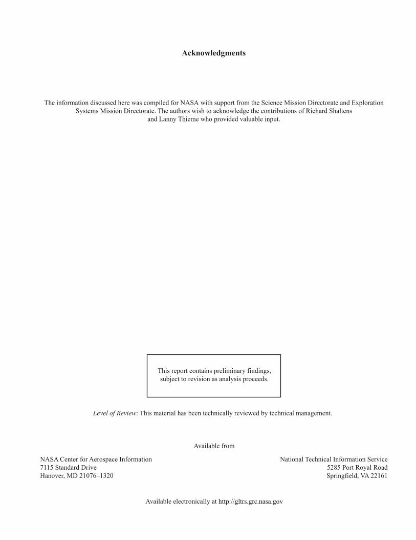
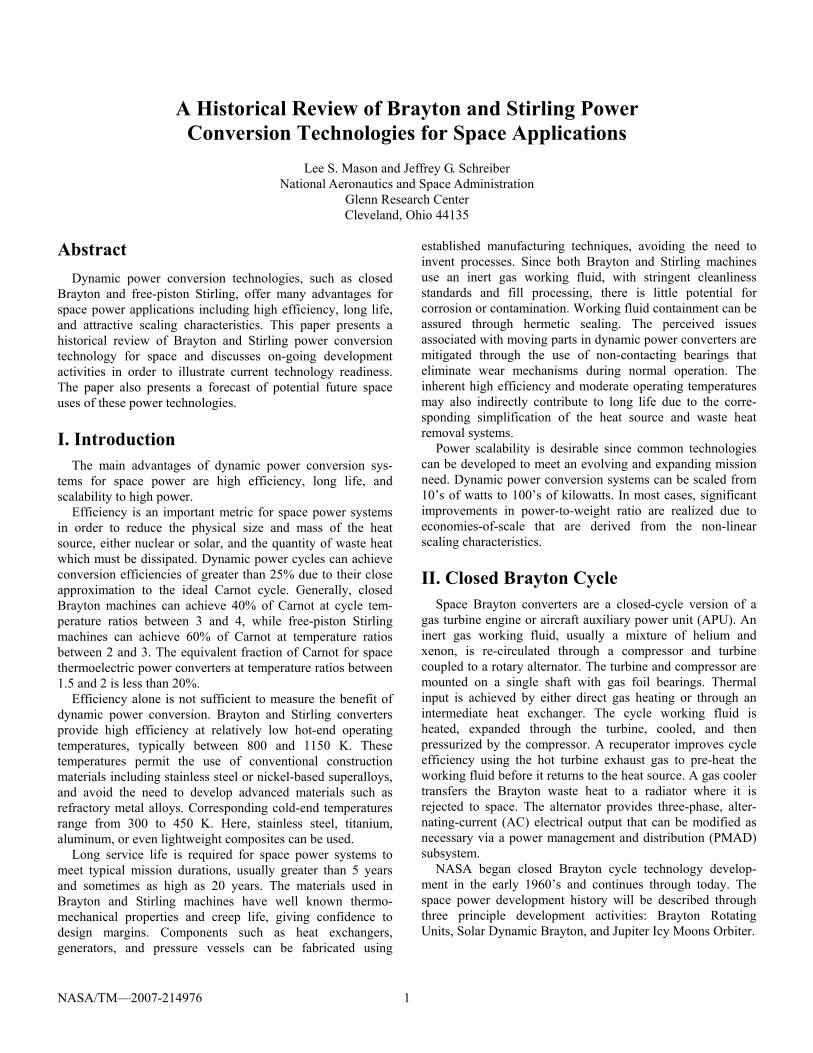
The Brayton Rotating Unit (BRU) Project (1968 to 1978) was aimed at a high efficiency power conversion system for isotope, reactor, and solar receiver heat sources.1 It was designed for operation from 2.25 to 10.5 kWe depending on the charge pressure of the working fluid, a helium-xenon mixture with molecular weight (MW) of 83.8 g/mol. Four BRU units, as shown in figure 1, were fabricated by AiRe-search and tested at NASA Lewis Research Center (now Glenn Research Center). A Brayton Heat Exchanger Unit (BHXU), figure 2, was also built that combined a 95% effective gas-to-gas recuperator and a Dow-Corning 200 (DC-200) gas cooler.2
The BRU system was designed for operation at a turbine inlet temperature of 1144 K, compressor inlet temperature of 300 K, and maximum pressure of 310 kPa. The rotating assembly consisted of a radial in-flow turbine, centrifugal compressor, and a liquid cooled alternator on tilt-pad bearings operating at 36000 rpm. The project successfully demon-strated manufacturing and assembly methods, a jacking gas startup technique, material compatibility, and high efficiency conversion (up to 32%). The BRU mass was 65 kg and the BHXU was 200 kg.
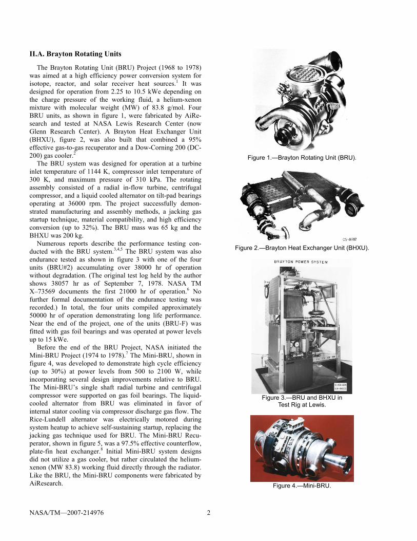
Numerous reports describe the performance testing con-ducted with the BRU system.3,4,5 The BRU system was also endurance tested as shown in figure 3 with one of the four units (BRU#2) accumulating over 38000 hr of operation without degradation. (The original test log held by the author shows 38057 hr as of September 7, 1978. NASA TM X–73569 documents the first 21000 hr of operation.6 No further formal documentation of the endurance testing was recorded.) In total, the four units compiled approximately 50000 hr of operation demonstrating long life performance. Near the end of the project, one of the units (BRU-F) was fitted with gas foil bearings and was operated at power levels up to 15 kWe.
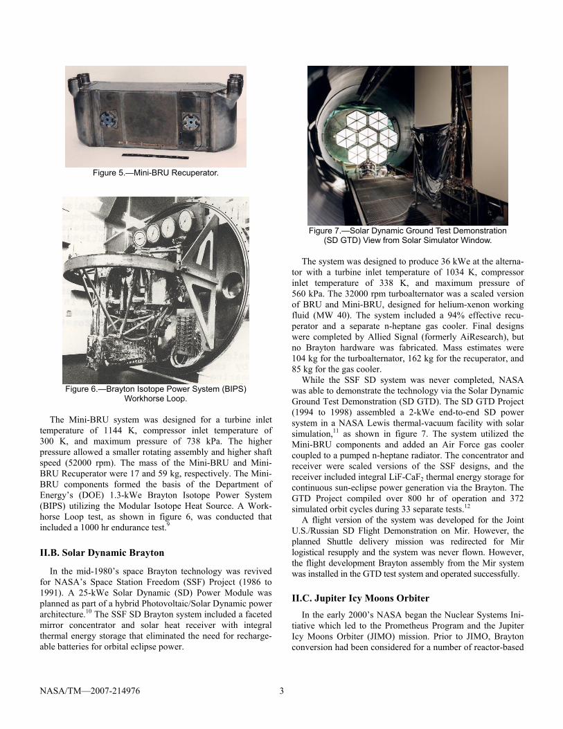
Before the end of the BRU Project, NASA initiated the Mini-BRU Project (1974 to 1978).7 The Mini-BRU, shown in figure 4, was developed to demonstrate high cycle efficiency (up to 30%) at power levels from 500 to 2100 W, while incorporating several design improvements relative to BRU. The Mini-BRU’s single shaft radial turbine and centrifugal compressor were supported on gas foil bearings. The liquid-cooled alternator from BRU was eliminated in favor of internal stator cooling via compressor discharge gas flow. The Rice-Lundell alternator was electrically motored during system heatup to achieve self-sustaining startup, replacing the jacking gas technique used for BRU. The Mini-BRU Recu-perator, shown in figure 5, was a 97.5% effective counterflow, plate-fin heat exchanger.8 Initial Mini-BRU system designs did not utilize a gas cooler, but rather circulated the helium-xenon (MW 83.8) working fluid directly through the radiator. Like the BRU, the Mini-BRU components were fabricated by AiResearch.
Figure 1.—Brayton Rotating Unit (BRU).
Figure 2.—Brayton Heat Exchanger Unit (BHXU).
Figure 3.—BRU and BHXU in
Test Rig at Lewis.
Figure 4.—Mini-BRU.
NASA/TM—2007-214976 3
Figure 5.—Mini-BRU Recuperator.
Figure 6.—Brayton Isotope Power System (BIPS)
Workhorse Loop.
The Mini-BRU system was designed for a turbine inlet temperature of 1144 K, compressor inlet temperature of 300 K, and maximum pressure of 738 kPa. The higher pressure allowed a smaller rotating assembly and higher shaft speed (52000 rpm). The mass of the Mini-BRU and Mini-BRU Recuperator were 17 and 59 kg, respectively. The Mini-BRU components formed the basis of the Department of Energy’s (DOE) 1.3-kWe Brayton Isotope Power System (BIPS) utilizing the Modular Isotope Heat Source. A Work-horse Loop test, as shown in figure 6, was conducted that included a 1000 hr endurance test.9
II.B. Solar Dynamic Brayton
In the mid-1980’s space Brayton technology was revived for NASA’s Space Station Freedom (SSF) Project (1986 to 1991). A 25-kWe Solar Dynamic (SD) Power Module was planned as part of a hybrid Photovoltaic/Solar Dynamic power architecture.10 The SSF SD Brayton system included a faceted mirror concentrator and solar heat receiver with integral thermal energy storage that eliminated the need for recharge-able batteries for orbital eclipse power.
Figure 7.—Solar Dynamic Ground Test Demonstration
(SD GTD) View from Solar Simulator Window. The system was designed to produce 36 kWe at the alterna-
tor with a turbine inlet temperature of 1034 K, compressor inlet temperature of 338 K, and maximum pressure of 560 kPa. The 32000 rpm turboalternator was a scaled version of BRU and Mini-BRU, designed for helium-xenon working fluid (MW 40). The system included a 94% effective recu-perator and a separate n-heptane gas cooler. Final designs were completed by Allied Signal (formerly AiResearch), but no Brayton hardware was fabricated. Mass estimates were 104 kg for the turboalternator, 162 kg for the recuperator, and 85 kg for the gas cooler.
While the SSF SD system was never completed, NASA was able to demonstrate the technology via the Solar Dynamic Ground Test Demonstration (SD GTD). The SD GTD Project (1994 to 1998) assembled a 2-kWe end-to-end SD power system in a NASA Lewis thermal-vacuum facility with solar simulation,11 as shown in figure 7. The system utilized the Mini-BRU components and added an Air Force gas cooler coupled to a pumped n-heptane radiator. The concentrator and receiver were scaled versions of the SSF designs, and the receiver included integral LiF-CaF2 thermal energy storage for continuous sun-eclipse power generation via the Brayton. The GTD Project compiled over 800 hr of operation and 372 simulated orbit cycles during 33 separate tests.12
A flight version of the system was developed for the Joint U.S./Russian SD Flight Demonstration on Mir. However, the planned Shuttle delivery mission was redirected for Mir logistical resupply and the system was never flown. However, the flight development Brayton assembly from the Mir system was installed in the GTD test system and operated successfully.
II.C. Jupiter Icy Moons Orbiter In the early 2000’s NASA began the Nuclear Systems Ini-
tiative which led to the Prometheus Program and the Jupiter Icy Moons Orbiter (JIMO) mission. Prior to JIMO, Brayton conversion had been considered for a number of reactor-based
NASA/TM—2007-214976 4
space power systems.13,14,15 Near the end of the SP-100 Space Reactor Program, a 20-kWe Brayton system, based on BRU technology, was selected as a low risk replacement to the thermoelectric baseline for an early flight demonstration.
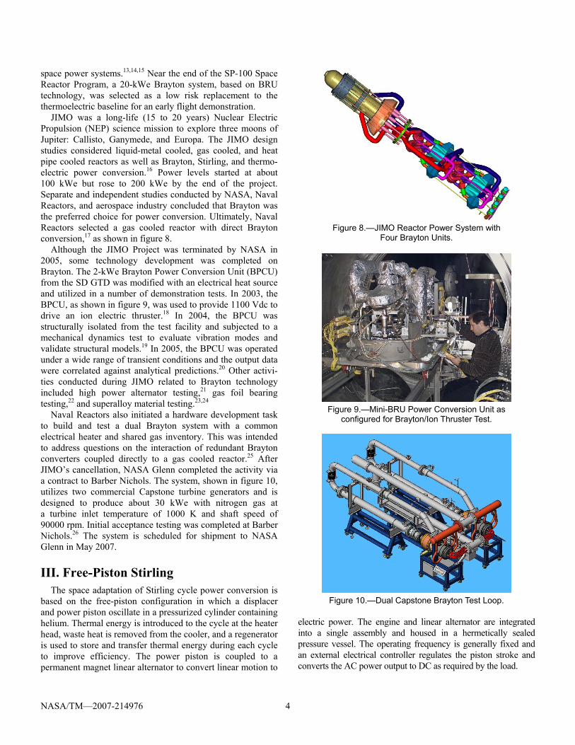
JIMO was a long-life (15 to 20 years) Nuclear Electric Propulsion (NEP) science mission to explore three moons of Jupiter: Callisto, Ganymede, and Europa. The JIMO design studies considered liquid-metal cooled, gas cooled, and heat pipe cooled reactors as well as Brayton, Stirling, and thermo-electric power conversion.16 Power levels started at about 100 kWe but rose to 200 kWe by the end of the project. Separate and independent studies conducted by NASA, Naval Reactors, and aerospace industry concluded that Brayton was the preferred choice for power conversion. Ultimately, Naval Reactors selected a gas cooled reactor with direct Brayton conversion,17 as shown in figure 8.
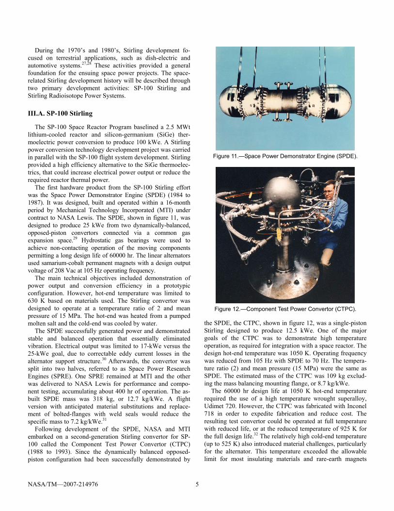
Although the JIMO Project was terminated by NASA in 2005, some technology development was completed on Brayton. The 2-kWe Brayton Power Conversion Unit (BPCU) from the SD GTD was modified with an electrical heat source and utilized in a number of demonstration tests. In 2003, the BPCU, as shown in figure 9, was used to provide 1100 Vdc to drive an ion electric thruster.18 In 2004, the BPCU was structurally isolated from the test facility and subjected to a mechanical dynamics test to evaluate vibration modes and validate structural models.19 In 2005, the BPCU was operated under a wide range of transient conditions and the output data were correlated against analytical predictions.20 Other activi-ties conducted during JIMO related to Brayton technology included high power alternator testing,21 gas foil bearing testing,22 and superalloy material testing.23,24
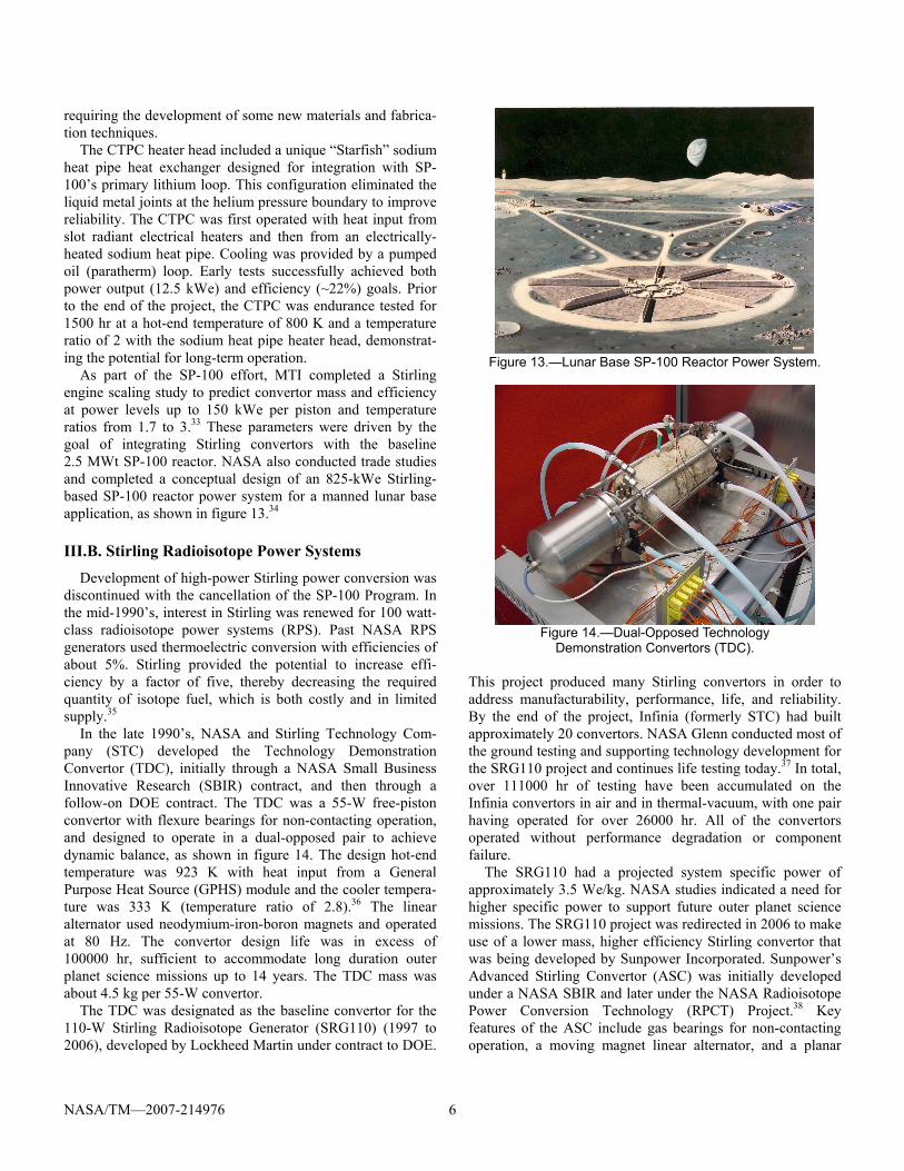
Naval Reactors also initiated a hardware development task to build and test a dual Brayton system with a common electrical heater and shared gas inventory. This was intended to address questions on the interaction of redundant Brayton converters coupled directly to a gas cooled reactor.25 After JIMO’s cancellation, NASA Glenn completed the activity via a contract to Barber Nichols. The system, shown in figure 10, utilizes two commercial Capstone turbine generators and is designed to produce about 30 kWe with nitrogen gas at a turbine inlet temperature of 1000 K and shaft speed of 90000 rpm. Initial acceptance testing was completed at Barber Nichols.26 The system is scheduled for shipment to NASA Glenn in May 2007.
III. Free-Piston Stirling The space adaptation of Stirling cycle power conversion is
based on the free-piston configuration in which a displacer and power piston oscillate in a pressurized cylinder containing helium. Thermal energy is introduced to the cycle at the heater head, waste heat is removed from the cooler, and a regenerator is used to store and transfer thermal energy during each cycle to improve efficiency. The power piston is coupled to a permanent magnet linear alternator to convert linear motion to
Figure 8.—JIMO Reactor Power System with
Four Brayton Units.
Figure 9.—Mini-BRU Power Conversion Unit as configured for Brayton/Ion Thruster Test.
Figure 10.—Dual Capstone Brayton Test Loop.
electric power. The engine and linear alternator are integrated into a single assembly and housed in a hermetically sealed pressure vessel. The operating frequency is generally fixed and an external electrical controller regulates the piston stroke and converts the AC power output to DC as required by the load.
NASA/TM—2007-214976 5
During the 1970’s and 1980’s, Stirling development fo-cused on terrestrial applications, such as dish-electric and automotive systems.27,28 These activities provided a general foundation for the ensuing space power projects. The space-related Stirling development history will be described through two primary development activities: SP-100 Stirling and Stirling Radioisotope Power Systems.
III.A. SP-100 Stirling
The SP-100 Space Reactor Program baselined a 2.5 MWt lithium-cooled reactor and silicon-germanium (SiGe) ther-moelectric power conversion to produce 100 kWe. A Stirling power conversion technology development project was carried in parallel with the SP-100 flight system development. Stirling provided a high efficiency alternative to the SiGe thermoelec-trics, that could increase electrical power output or reduce the required reactor thermal power.
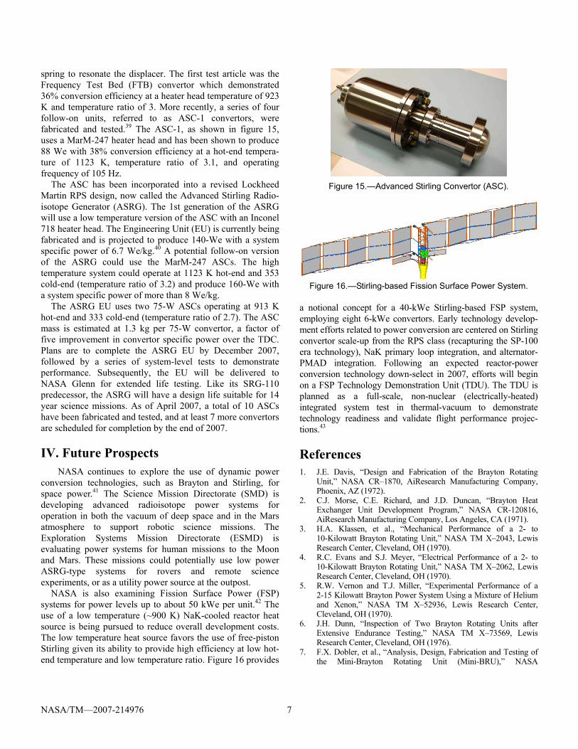
The first hardware product from the SP-100 Stirling effort was the Space Power Demonstrator Engine (SPDE) (1984 to 1987). It was designed, built and operated within a 16-month period by Mechanical Technology Incorporated (MTI) under contract to NASA Lewis. The SPDE, shown in figure 11, was designed to produce 25 kWe from two dynamically-balanced, opposed-piston convertors connected via a common gas expansion space.29 Hydrostatic gas bearings were used to achieve non-contacting operation of the moving components permitting a long design life of 60000 hr. The linear alternators used samarium-cobalt permanent magnets with a design output voltage of 208 Vac at 105 Hz operating frequency.
The main technical objectives included demonstration of power output and conversion efficiency in a prototypic configuration. However, hot-end temperature was limited to 630 K based on materials used. The Stirling convertor was designed to operate at a temperature ratio of 2 and mean pressure of 15 MPa. The hot-end was heated from a pumped molten salt and the cold-end was cooled by water.
The SPDE successfully generated power and demonstrated stable and balanced operation that essentially eliminated vibration. Electrical output was limited to 17-kWe versus the 25-kWe goal, due to correctable eddy current losses in the alternator support structure.30 Afterwards, the convertor was split into two halves, referred to as Space Power Research Engines (SPRE). One SPRE remained at MTI and the other was delivered to NASA Lewis for performance and compo-nent testing, accumulating about 400 hr of operation. The as-built SPDE mass was 318 kg, or 12.7 kg/kWe. A flight version with anticipated material substitutions and replace-ment of bolted-flanges with weld seals would reduce the specific mass to 7.2 kg/kWe.31
Following development of the SPDE, NASA and MTI embarked on a second-generation Stirling convertor for SP-100 called the Component Test Power Convertor (CTPC) (1988 to 1993). Since the dynamically balanced opposed-piston configuration had been successfully demonstrated by
Figure 11.—Space Power Demonstrator Engine (SPDE).
Figure 12.—Component Test Power Convertor (CTPC).
the SPDE, the CTPC, shown in figure 12, was a single-piston Stirling designed to produce 12.5 kWe. One of the major goals of the CTPC was to demonstrate high temperature operation, as required for integration with a space reactor. The design hot-end temperature was 1050 K. Operating frequency was reduced from 105 Hz with SPDE to 70 Hz. The tempera-ture ratio (2) and mean pressure (15 MPa) were the same as SPDE. The estimated mass of the CTPC was 109 kg exclud-ing the mass balancing mounting flange, or 8.7 kg/kWe.
The 60000 hr design life at 1050 K hot-end temperature required the use of a high temperature wrought superalloy, Udimet 720. However, the CTPC was fabricated with Inconel 718 in order to expedite fabrication and reduce cost. The resulting test convertor could be operated at full temperature with reduced life, or at the reduced temperature of 925 K for the full design life.32 The relatively high cold-end temperature (up to 525 K) also introduced material challenges, particularly for the alternator. This temperature exceeded the allowable limit for most insulating materials and rare-earth magnets
NASA/TM—2007-214976 6
requiring the development of some new materials and fabrica-tion techniques.
The CTPC heater head included a unique “Starfish” sodium heat pipe heat exchanger designed for integration with SP-100’s primary lithium loop. This configuration eliminated the liquid metal joints at the helium pressure boundary to improve reliability. The CTPC was first operated with heat input from slot radiant electrical heaters and then from an electrically-heated sodium heat pipe. Cooling was provided by a pumped oil (paratherm) loop. Early tests successfully achieved both power output (12.5 kWe) and efficiency (~22%) goals. Prior to the end of the project, the CTPC was endurance tested for 1500 hr at a hot-end temperature of 800 K and a temperature ratio of 2 with the sodium heat pipe heater head, demonstrat-ing the potential for long-term operation.
As part of the SP-100 effort, MTI completed a Stirling engine scaling study to predict convertor mass and efficiency at power levels up to 150 kWe per piston and temperature ratios from 1.7 to 3.33 These parameters were driven by the goal of integrating Stirling convertors with the baseline 2.5 MWt SP-100 reactor. NASA also conducted trade studies and completed a conceptual design of an 825-kWe Stirling-based SP-100 reactor power system for a manned lunar base application, as shown in figure 13.34
III.B. Stirling Radioisotope Power Systems Development of high-power Stirling power conversion was
discontinued with the cancellation of the SP-100 Program. In the mid-1990’s, interest in Stirling was renewed for 100 watt-class radioisotope power systems (RPS). Past NASA RPS generators used thermoelectric conversion with efficiencies of about 5%. Stirling provided the potential to increase effi-ciency by a factor of five, thereby decreasing the required quantity of isotope fuel, which is both costly and in limited supply.35
In the late 1990’s, NASA and Stirling Technology Com-pany (STC) developed the Technology Demonstration Convertor (TDC), initially through a NASA Small Business Innovative Research (SBIR) contract, and then through a follow-on DOE contract. The TDC was a 55-W free-piston convertor with flexure bearings for non-contacting operation, and designed to operate in a dual-opposed pair to achieve dynamic balance, as shown in figure 14. The design hot-end temperature was 923 K with heat input from a General Purpose Heat Source (GPHS) module and the cooler tempera-ture was 333 K (temperature ratio of 2.8).36 The linear alternator used neodymium-iron-boron magnets and operated at 80 Hz. The convertor design life was in excess of 100000 hr, sufficient to accommodate long duration outer planet science missions up to 14 years. The TDC mass was about 4.5 kg per 55-W convertor.
The TDC was designated as the baseline convertor for the 110-W Stirling Radioisotope Generator (SRG110) (1997 to 2006), developed by Lockheed Martin under contract to DOE.
Figure 13.—Lunar Base SP-100 Reactor Power System.
Figure 14.—Dual-Opposed Technology
Demonstration Convertors (TDC).
This project produced many Stirling convertors in order to address manufacturability, performance, life, and reliability. By the end of the project, Infinia (formerly STC) had built approximately 20 convertors. NASA Glenn conducted most of the ground testing and supporting technology development for the SRG110 project and continues life testing today.37 In total, over 111000 hr of testing have been accumulated on the Infinia convertors in air and in thermal-vacuum, with one pair having operated for over 26000 hr. All of the convertors operated without performance degradation or component failure.
The SRG110 had a projected system specific power of approximately 3.5 We/kg. NASA studies indicated a need for higher specific power to support future outer planet science missions. The SRG110 project was redirected in 2006 to make use of a lower mass, higher efficiency Stirling convertor that was being developed by Sunpower Incorporated. Sunpower’s Advanced Stirling Convertor (ASC) was initially developed under a NASA SBIR and later under the NASA Radioisotope Power Conversion Technology (RPCT) Project.38 Key features of the ASC include gas bearings for non-contacting operation, a moving magnet linear alternator, and a planar
NASA/TM—2007-214976 7
spring to resonate the displacer. The first test article was the Frequency Test Bed (FTB) convertor which demonstrated 36% conversion efficiency at a heater head temperature of 923 K and temperature ratio of 3. More recently, a series of four follow-on units, referred to as ASC-1 convertors, were fabricated and tested.39 The ASC-1, as shown in figure 15, uses a MarM-247 heater head and has been shown to produce 88 We with 38% conversion efficiency at a hot-end tempera-ture of 1123 K, temperature ratio of 3.1, and operating frequency of 105 Hz.
The ASC has been incorporated into a revised Lockheed Martin RPS design, now called the Advanced Stirling Radio-isotope Generator (ASRG). The 1st generation of the ASRG will use a low temperature version of the ASC with an Inconel 718 heater head. The Engineering Unit (EU) is currently being fabricated and is projected to produce 140-We with a system specific power of 6.7 We/kg.40 A potential follow-on version of the ASRG could use the MarM-247 ASCs. The high temperature system could operate at 1123 K hot-end and 353 cold-end (temperature ratio of 3.2) and produce 160-We with a system specific power of more than 8 We/kg.
The ASRG EU uses two 75-W ASCs operating at 913 K hot-end and 333 cold-end (temperature ratio of 2.7). The ASC mass is estimated at 1.3 kg per 75-W convertor, a factor of five improvement in convertor specific power over the TDC. Plans are to complete the ASRG EU by December 2007, followed by a series of system-level tests to demonstrate performance. Subsequently, the EU will be delivered to NASA Glenn for extended life testing. Like its SRG-110 predecessor, the ASRG will have a design life suitable for 14 year science missions. As of April 2007, a total of 10 ASCs have been fabricated and tested, and at least 7 more convertors are scheduled for completion by the end of 2007.
IV. Future Prospects NASA continues to explore the use of dynamic power
conversion technologies, such as Brayton and Stirling, for space power.41 The Science Mission Directorate (SMD) is developing advanced radioisotope power systems for operation in both the vacuum of deep space and in the Mars atmosphere to support robotic science missions. The Exploration Systems Mission Directorate (ESMD) is evaluating power systems for human missions to the Moon and Mars. These missions could potentially use low power ASRG-type systems for rovers and remote science experiments, or as a utility power source at the outpost.
NASA is also examining Fission Surface Power (FSP) systems for power levels up to about 50 kWe per unit.42 The use of a low temperature (~900 K) NaK-cooled reactor heat source is being pursued to reduce overall development costs. The low temperature heat source favors the use of free-piston Stirling given its ability to provide high efficiency at low hot-end temperature and low temperature ratio. Figure 16 provides
Figure 15.—Advanced Stirling Convertor (ASC).
Figure 16.—Stirling-based Fission Surface Power System.
a notional concept for a 40-kWe Stirling-based FSP system, employing eight 6-kWe convertors. Early technology develop-ment efforts related to power conversion are centered on Stirling convertor scale-up from the RPS class (recapturing the SP-100 era technology), NaK primary loop integration, and alternator-PMAD integration. Following an expected reactor-power conversion technology down-select in 2007, efforts will begin on a FSP Technology Demonstration Unit (TDU). The TDU is planned as a full-scale, non-nuclear (electrically-heated) integrated system test in thermal-vacuum to demonstrate technology readiness and validate flight performance projec-tions.43
References 1. J.E. Davis, “Design and Fabrication of the Brayton Rotating
Unit,” NASA CR–1870, AiResearch Manufacturing Company, Phoenix, AZ (1972).
2. C.J. Morse, C.E. Richard, and J.D. Duncan, “Brayton Heat Exchanger Unit Development Program,” NASA CR-120816, AiResearch Manufacturing Company, Los Angeles, CA (1971).
3. H.A. Klassen, et al., “Mechanical Performance of a 2- to 10-Kilowatt Brayton Rotating Unit,” NASA TM X–2043, Lewis Research Center, Cleveland, OH (1970).
4. R.C. Evans and S.J. Meyer, “Electrical Performance of a 2- to 10-Kilowatt Brayton Rotating Unit,” NASA TM X–2062, Lewis Research Center, Cleveland, OH (1970).
5. R.W. Vernon and T.J. Miller, “Experimental Performance of a 2-15 Kilowatt Brayton Power System Using a Mixture of Helium and Xenon,” NASA TM X–52936, Lewis Research Center, Cleveland, OH (1970).
6. J.H. Dunn, “Inspection of Two Brayton Rotating Units after Extensive Endurance Testing,” NASA TM X–73569, Lewis Research Center, Cleveland, OH (1976).
7. F.X. Dobler, et al., “Analysis, Design, Fabrication and Testing of the Mini-Brayton Rotating Unit (Mini-BRU),” NASA
NASA/TM—2007-214976 8
CR–159441, AiResearch Manufacturing Company, Phoenix, AZ (1978).
8. J.J. Killackey, R. Graves, and G. Mosinskis, “Design and Fabrication of the Mini-Brayton Recuperator (MBR),” NASA CR–159429, AiResearch Manufacturing Company, Torrance, CA (1978).
9. J.E. McCormick, “Brayton Isotope Power System Phase 1 Final Report,” Report No. 31–2919, AiResearch Manufacturing Company, Phoenix, AZ (1978).
10. Staff of the Solar Dynamic Power Systems Branch, “Solar Dynamic Power System Development for Space Station Freedom,” NASA RP–1310, Lewis Research Center, Cleveland, OH (1993).
11. D. Alexander, “2 kWe Solar Dynamic Ground Test Demonstration Project,” NASA CR–198423, AlliedSignal Aerospace, Tempe AZ (1997).
12. R.K. Shaltens and L.S. Mason, “800 Hours of Operational Experience From a 2 kWe Solar Dynamic System,” NASA/TM—1999-208840, Lewis Research Center, Cleveland OH (1999).
13. M.G. Coombs, C.J. Morse, and C.E. Richard, “Nuclear Brayton Cycle Heat Exchanger and Duct Assembly,” NASA CR–72783, AiResearch Manufacturing Company, Los Angeles CA (1970).
14. A. Harper, “Study of Reactor Brayton Power Systems for Nuclear Electric Spacecraft,” Report No. 31–3321, AiResearch Manufacturing Company, Phoenix AZ (1979).
15. L.S. Mason, et al., “SP–100 Reactor With Brayton Conversion for Lunar Surface Applications,” NASA TM–105637, Lewis Research Center, Cleveland OH (1992).
16. L.S. Mason, “A Power Conversion Concept for the Jupiter Icy Moons Orbiter,” NASA/TM—2003-212596, Glenn Research Center, Cleveland OH (2003).
17. J. Ashcroft and C. Eshelman, “Summary of NR Program Prometheus Efforts,” Proc. of the Space Technology and Applications International Forum – STAIF 2007, Albuquerque NM (2007).
18. D.S. Hervol, et al., “Experimental Investigations from the Operation of a 2 kW Brayton Power Conversion Unit and a Xenon Ion Thruster,” NASA/TM—2004-212960, Glenn Research Center, Cleveland OH (2004).
19. D.R. Ludwiczak, et al., “Verification of a 2 kWe Closed-Brayton-Cycle Power System Mechanical Dynamics Model,” Proc. of the Space Technology and Applications International Forum – STAIF 2005, Albuquerque NM (2005)
20. P.K. Johnson and D.S. Hervol, “Experimental Validation of a Closed Brayton Cycle System Transient Simulation,” NASA/CR—2006-214239, Glenn Research Center, Cleveland OH (2006).
21. A. Birchenough and D.S. Hervol, “Operational Results from a High Power Alternator Test Bed,” Proc. of the Space Technology and Applications International Forum – STAIF 2007, Albuquerque NM (2007).
22. S.A. Howard, et al., “Gas Foil Bearing Technology Advancements for Closed Brayton Cycle Turbines,” NASA/TM—2007-214470, Glenn Research Center, Cleveland OH (2007).
23. T.P. Gabb, J. Gayda, and A. Garg, “Creep Property Characterization of Potential Brayton Cycle Impeller and Duct Materials,” Proc. of the Space Technology and Applications International Forum – STAIF 2007, Albuquerque, NM (2007).
24. I.E. Locci, et al., “High Temperature Stability of Dissimilar Metal Joints in Fission Surface Power Systems,” Proc. of the Space Technology and Applications International Forum – STAIF 2007, Albuquerque, NM (2007).
25. P.K. Johnson and L.S. Mason, “Performance and Operational Characteristics for a Dual Brayton Space Power System with
Common Gas Inventory,” NASA/TM—2006-214393, Glenn Research Center, Cleveland, OH (2006).
26. P.K. Johnson and L.S. Mason, “Initial Test Results of a Dual Closed-Brayton-Cycle Power Conversion System,” Proc. of the Space Nuclear Conference – SNC 2007, Boston MA (2007).
27. R.K. Shaltens and J.G. Schreiber, “Preliminary Designs for 25 kWe Advanced Stirling Conversion Systems for Dish Electric Applications,” NASA TM–103188, Lewis Research Center, Cleveland, OH (1990).
28. W.D. Ernst and R.K. Shaltens, “Automotive Stirling Engine Development Project,” NASA CR–190780, Mechanical Technology Incorporated, Latham NY and Lewis Research Center, Cleveland, OH (1997).
29. A.T. Brown, “Space Power Demonstrator Engine – Phase I Final Report,” NASA CR–179555, Mechanical Technology Incorporated, Latham NY (1987).
30. G. Dochet, “SPDE/SPRE Final Summary Report,” NASA CR–187086, Mechanical Technology Incorporated, Latham, NY (1993).
31. J.G. Slaby, “Overview of Free-Piston Stirling Engine Technology for Space Power Application,” NASA TM–88886, Lewis Research Center, Cleveland, OH (1987).
32. M. Dhar, “Stirling Space Engine Program, Volume 1 Final Report” NASA/CR—1999-209164/VOL1, Mechanical Technology Incorporated, Latham, NY (1999).
33. D. Jones, “Space Power Free-Piston Stirling Engine Scaling Study,” NASA CR–182218, Mechanical Technology Incorporated, Latham, NY (1989).
34. L.S. Mason, H.S. Bloomfield, and D.C. Hainley, “SP–100 Power System Conceptual Design for Lunar Base Applications,” NASA TM–102090, Lewis Research Center, Cleveland, OH (1989).
35. J.G. Schreiber, “Status of the NASA Stirling Radioisotope Project,” Proc. of the International Stirling Forum – ISF 2006, Osnabruck, Germany (2006).
36. S. Qiu, “Developing a Free-Piston Stirling Convertor for Advanced Radioisotope Space Power Systems,” Proc. of the Space Technology and Applications International Forum – STAIF 2002, Albuquerque, NM (2002).
37. J.G. Schreiber, “Summary of Stirling Convertor Testing at the NASA Glenn Research Center,” NASA/TM—2006-214429, Glenn Research Center, Cleveland, OH (2006).
38. W.A. Wong, “Advanced Radioisotope Power Conversion Technology Research and Development,” NASA/TM—2004-213352, Glenn Research Center, Cleveland, OH (2004).
39. J.G. Wood, et al., “Advanced Stirling Convertor (ASC) Phase III Progress Update,” Proc. of the Space Technology and Applications International Forum – STAIF 2007, Albuquerque, NM (2007).
40. J. Chan, J.G. Wood, and J.G. Schreiber, “Development of Advanced Stirling Radioisotope Generator for Space Exploration,” Proc. of the Space Technology and Applications International Forum – STAIF 2007, Albuquerque, NM (2007).
41. R.K. Shaltens, “Future Opportunities for Dynamic Power Systems for NASA Missions,” Proc. of the International Stirling Forum – ISF2006, Osnabruck, Germany (2006).
42. L.S. Mason, “A Comparison of Fission Power System Options for Lunar and Mars Surface Applications,” NASA/TM—2006-214120, Glenn Research Center, Cleveland, OH (2006).
43. L.S. Mason, “A Practical Approach to Starting Fission Surface Power Development,” NASA/TM—2006-214366, Glenn Research Center, Cleveland, OH (2006).
REPORT DOCUMENTATION PAGE Form Approved OMB No. 0704-0188
The public reporting burden for this collection of information is estimated to average 1 hour per response, including the time for reviewing instructions, searching existing data sources, gathering and maintaining the data needed, and completing and reviewing the collection of information. Send comments regarding this burden estimate or any other aspect of this collection of information, including suggestions for reducing this burden, to Department of Defense, Washington Headquarters Services, Directorate for Information Operations and Reports (0704-0188), 1215 Jefferson Davis Highway, Suite 1204, Arlington, VA 22202-4302. Respondents should be aware that notwithstanding any other provision of law, no person shall be subject to any penalty for failing to comply with a collection of information if it does not display a currently valid OMB control number. PLEASE DO NOT RETURN YOUR FORM TO THE ABOVE ADDRESS. 1. REPORT DATE (DD-MM-YYYY) 01-11-2007
2. REPORT TYPE Technical Memorandum
3. DATES COVERED (From - To)
4. TITLE AND SUBTITLE A Historical Review of Brayton and Stirling Power Conversion Technologies for Space Applications
5a. CONTRACT NUMBER
5b. GRANT NUMBER
5c. PROGRAM ELEMENT NUMBER
6. AUTHOR(S) Mason, Lee, S.; Schreiber, Jeffrey, G.
5d. PROJECT NUMBER
5e. TASK NUMBER
5f. WORK UNIT NUMBER WBS 850661.04.01.03
7. PERFORMING ORGANIZATION NAME(S) AND ADDRESS(ES) National Aeronautics and Space Administration John H. Glenn Research Center at Lewis Field Cleveland, Ohio 44135-3191
8. PERFORMING ORGANIZATION REPORT NUMBER E-16140
9. SPONSORING/MONITORING AGENCY NAME(S) AND ADDRESS(ES) National Aeronautics and Space Administration Washington, DC 20546-0001
10. SPONSORING/MONITORS ACRONYM(S) NASA
11. SPONSORING/MONITORING REPORT NUMBER NASA/TM-2007-214976
12. DISTRIBUTION/AVAILABILITY STATEMENT Unclassified-Unlimited Subject Category: 20 Available electronically at http://gltrs.grc.nasa.gov This publication is available from the NASA Center for AeroSpace Information, 301-621-0390
13. SUPPLEMENTARY NOTES
14. ABSTRACT Dynamic power conversion technologies, such as closed Brayton and free-piston Stirling, offer many advantages for space power applications including high efficiency, long life, and attractive scaling characteristics. This paper presents a historical review of Brayton and Stirling power conversion technology for space and discusses on-going development activities in order to illustrate current technology readiness. The paper also presents a forecast of potential future space uses of these power technologies. 15. SUBJECT TERMS Brayton cycle; Stirling cycle; Energy conversion
16. SECURITY CLASSIFICATION OF: 17. LIMITATION OF ABSTRACT UU
18. NUMBER OF PAGES
14
19a. NAME OF RESPONSIBLE PERSON STI Help Desk (email:[email protected])
a. REPORT U
b. ABSTRACT U
c. THIS PAGE U
19b. TELEPHONE NUMBER (include area code) 301-621-0390
Standard Form 298 (Rev. 8-98)Prescribed by ANSI Std. Z39-18