Embed Size (px)
Citation preview
Challenge G: An even more competitive and cost efficient railway
A High-performance Inspection System of Tunnel Wall DeformationUsing Continuous Scan Image
Masato Ukai Nozomi NagamineRailway Technical Research Institute
2-8-38 Hikari-cho, Kokubunji-shi, Tokyo 185-8540, Japan
AbstractWe have developed an efficient tunnel scanner with line sensor cameras capable of taking
high-precision panoramic annular images of the surface of a tunnel lining at low cost. The system doesnot require a special vehicle, but instead can be mounted on railcars used for construction ormaintenance purposes. The photographic equipment involved is basic, and consists of cameras, lights,control devices and the like. A number of 5000-pixel line sensor cameras are mounted on the railcarand aimed at the tunnel walls. The railcar travels at about 20km/h, and can take images of the surfacesof a single-track tunnel with just one run. A double-track tunnel requires two runs (one on each track) toobtain images of the entire section, and continuous image-taking is possible for dozens of kilometersper run. In basic terms, only image-taking and recording are carried out on the railcar, with offlineprocessing of image data being performed elsewhere. The performance of this new system faroutstrips that of conventional photographic systems in terms of filming speed, recording time andmemory. The resolution is determined by the number of camera pixels in the cross-sectional direction,but depends on the running speed and scan rate for the longitudinal direction. Under ordinaryconditions, the pixel pitch setting is around 0.8 mm horizontally/vertically.
We also developed an image processing algorithm for the automatic detection of cracks. Generally,the images of cracks are darker than those of their surroundings, and take the form of indented,blackish wavy lines. Focusing on the existence of variations in the gradient of luminance along lineedges, we selected cracks with more detailed luminous variation than could be recognized by theresolution of the cameras. We then adopted a hysteresis threshold-processing method that wouldselect only edges joined to edges detected by high threshold values. Furthermore, we adopt thesub-pixel-style image processing algorithm based on a gradient filter developed to extract minutecracks (0.5mm width) from a wall image and measure the characteristic values such as width, length,direction etc. to a high degree of accuracy. It is possible to prognosticate the growth of cracks and rankthe degree of soundness based on this data. The method was applied to typical crack images tovalidate its effectiveness, and the experimental results show that the extraction performance of thealgorithm has the potential for sufficient accuracy.
Keywords : railway, tunnel, deformation, crack, water leakage, line-sensor camera, image processing
1. Introduction
Deformation affecting the structural soundness of railway tunnels (such as wall cracking) iscurrently inspected and treated through visual monitoring. However, the actual work environment is soadverse and the areas for monitoring are so extensive that it is very difficult to investigate alldeformation that develops on walls. In particular, it is hard to ascertain the full extent of minute cracksin dark tunnels. As the manner of inspection also varies by individual, there are additional problemsin terms of accuracy and objectivity as well as in the amount of work time required. The modernizationof maintenance and inspection methods is now an urgent business due to a shortage of labor and theaging of maintenance workers. The existing method [1], [2], which uses photography and lasers,presents problems with complexity, inspection speed, accuracy and data processing.
In view of these problems, we have developed and put into practical use a tunnel lining deformationinspection system consisting of an on-board photographing set-up containing a one-dimensional linesensor camera and a ground system that puts together images to generate a 360-degree panoramicview. Our proposed method would be more ‘high tech’ and has several benefits the conventionaltechnology does not. Operational costs could be less than with existing methods as there could be asignificant reduction in site staff time and corresponding reduction in possession shifts. Reduction innight time working, with a corresponding reduction in risks associated with site work anticipated.Proposed sub-pixel-style image processing approach offers an effective improvement over theconventional one.
Challenge G: An even more competitive and cost efficient railway
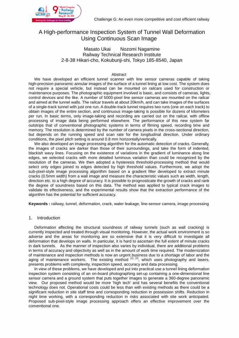
2. Outline of tunnel scanner systemWe have developed an efficient tunnel scanner with line sensor cameras capable of taking
high-precision panoramic annular images of the surface of a tunnel lining at low cost, as shown in Fig.1. The system does not require a special vehicle, but instead can be mounted on railcars used forconstruction or maintenance purposes. The photographic equipment involved is basic, and consists ofcameras, lights, control devices and the like. A number of 5150-pixel line sensor cameras are mountedon the railcar and aimed at the tunnel walls as shown in Fig. 1. The railcar travels at 10 to 30 km/h, andcan take images of the surfaces of a single-track tunnel with just one run. A double-track tunnelrequires two runs (one on each track) to obtain images of the entire section, and continuousimage-taking is possible for dozens of kilometers per run. In basic terms, only image-taking andrecording are carried out on the railcar, with off-line processing of image data being performedelsewhere. The performance of this new system far outstrips that of conventional photographicsystems in terms of filming speed, recording time and memory. The resolution is determined by thenumber of camera pixels in the cross-sectional direction, but depends on the running speed and scanrate for the longitudinal direction. Under ordinary conditions, the pixel pitch setting is around 0.8 mmhorizontally/vertically as shown in Table 1.
Specifications of Tunnel Scanner Inspection car and on-board equipment
Recording Equipment Line scan camera x 3 – 4 / Lighting Equipment x 10~Control Devices / Generator etc.
Recording Speed 20 km/h or moreResolution 5,150 pixels Pixel Size: 7μm×7μm Element Size: 36.05mm
Data Rate 40MHz, Maximum Scan Rate: 133μsRecording Resolution 0.5~1.0 mm/pixelLuminance 20,000 lx by HMI lighting equipmentUnfolded tunnel wall image Automatic matching by image mosaicing (off-line)Crack detection Automatic extraction by image processing (off-line)
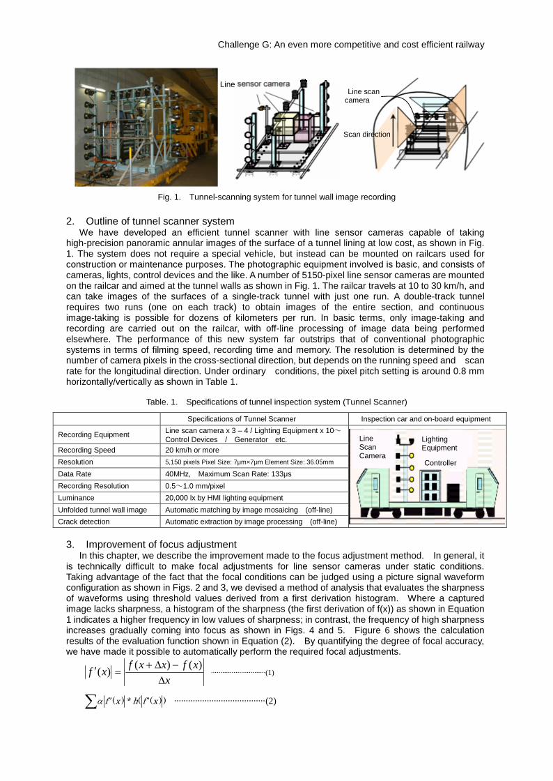
3. Improvement of focus adjustmentIn this chapter, we describe the improvement made to the focus adjustment method. In general, it
is technically difficult to make focal adjustments for line sensor cameras under static conditions.Taking advantage of the fact that the focal conditions can be judged using a picture signal waveformconfiguration as shown in Figs. 2 and 3, we devised a method of analysis that evaluates the sharpnessof waveforms using threshold values derived from a first derivation histogram. Where a capturedimage lacks sharpness, a histogram of the sharpness (the first derivation of f(x)) as shown in Equation1 indicates a higher frequency in low values of sharpness; in contrast, the frequency of high sharpnessincreases gradually coming into focus as shown in Figs. 4 and 5. Figure 6 shows the calculationresults of the evaluation function shown in Equation (2). By quantifying the degree of focal accuracy,we have made it possible to automatically perform the required focal adjustments.
x
xfxxfxf
)()()( ·····························(1)
))((*)( xfhxf ·······································(2)
Table. 1. Specifications of tunnel inspection system (Tunnel Scanner)
LineScanCamera
LightingEquipment
Controller
17
計
測
装
照
明
用
Line sensor cameraLine scan
camera
Scan direction
Fig. 1. Tunnel-scanning system for tunnel wall image recording
Challenge G: An even more competitive and cost efficient railway
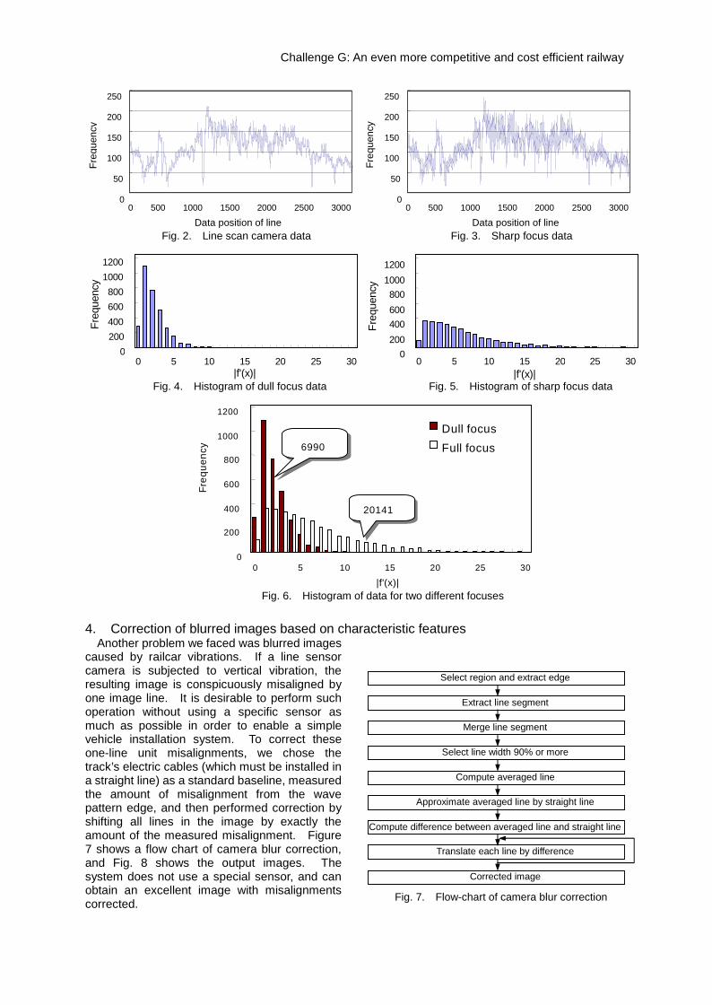
4. Correction of blurred images based on characteristic featuresAnother problem we faced was blurred images
caused by railcar vibrations. If a line sensorcamera is subjected to vertical vibration, theresulting image is conspicuously misaligned byone image line. It is desirable to perform suchoperation without using a specific sensor asmuch as possible in order to enable a simplevehicle installation system. To correct theseone-line unit misalignments, we chose thetrack’s electric cables (which must be installed ina straight line) as a standard baseline, measuredthe amount of misalignment from the wavepattern edge, and then performed correction byshifting all lines in the image by exactly theamount of the measured misalignment. Figure7 shows a flow chart of camera blur correction,and Fig. 8 shows the output images. Thesystem does not use a special sensor, and canobtain an excellent image with misalignmentscorrected.
Freq
uenc
y
0 5 10 15 20 25 30|f'(x)|
0200400
80010001200
600
0200400600800
10001200
0 5 10 15 20 25 30|f'(x)|
Freq
uenc
y
0
50
100
150
200
250
Data position of line0 500 1000 1500 2000 2500 3000
Freq
uenc
y
0
50
100
150
200
250
Data position of line0 500 1000 1500 2000 2500 3000
Freq
uenc
y
Freq
uenc
y
0
200
400
600
800
1000
1200
0 5 10 15 20 25 30
|f'(x)|
Dull focusFull focus
20141
6990
Fig. 2. Line scan camera data Fig. 3. Sharp focus data
e.
Fig. 4. Histogram of dull focus data Fig. 5. Histogram of sharp focus data
Fig. 6. Histogram of data for two different focuses
Compute difference between averaged line and straight line
Select region and extract edge
Extract line segment
Merge line segment
Approximate averaged line by straight line
Compute averaged line
Select line width 90% or more
Corrected image
Translate each line by difference
Fig. 7. Flow-chart of camera blur correction
Challenge G: An even more competitive and cost efficient railway
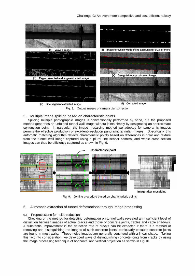
5. Multiple image splicing based on characteristic pointsSplicing multiple photographic images is conventionally performed by hand, but the proposed
method generates an unfolded tunnel wall image without joints simply by designating an approximateconjunction point. In particular, the image mosaicing method we adopted for panoramic imagespermits the effective production of excellent-resolution panoramic annular images. Specifically, thisautomatic matching algorithm detects characteristic points based on differences in color and texturefrom the tunnel wall image captured using a plural line sensor camera, and whole cross-sectionimages can thus be efficiently captured as shown in Fig. 9.
6. Automatic extraction of tunnel deformations through image processing
6.1 Preprocessing for noise reductionChecking of the method for detecting deformation on tunnel walls revealed an insufficient level of
distinction between images of actual cracks and those of concrete joints, cables and cable shadows.A substantial improvement in the detection rate of cracks can be expected if there is a method ofremoving and distinguishing the images of such concrete joints, particularly because concrete jointsare found in most walls. These noise images are generally continued with a linear shape. Takingthis fact into consideration, we developed ways of distinguishing concrete joints from cracks by usingthe image processing technique of horizontal and vertical projection as shown in Fig.10.
Characteristic point
Image after mosaicing
Fig. 9. Joining procedure based on characteristic points
Fig. 8. Output images of camera blur correction
(a) Waved image.
(c) Line segment extracted image
(e) Straight-line approximated image
(f) Corrected image
(d) Image for which width of line accounts for 90% or more
(b) Region selected and edge-extracted image
Challenge G: An even more competitive and cost efficient railway
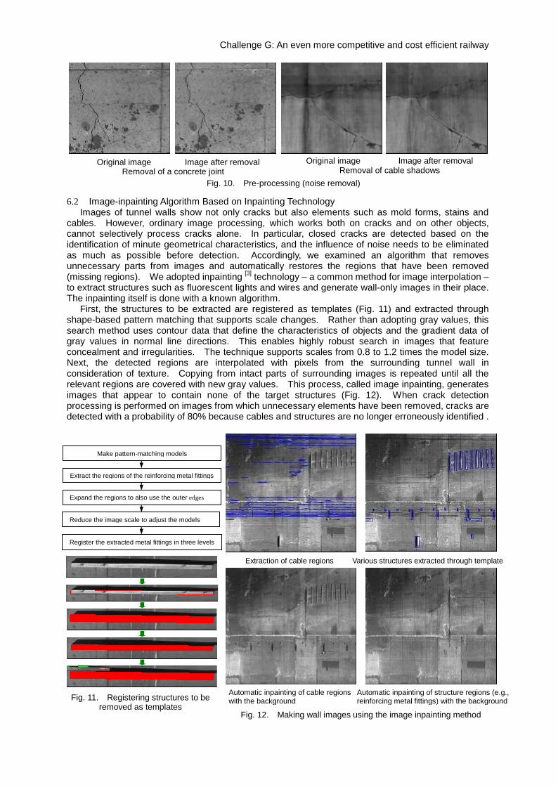
6.2 Image-inpainting Algorithm Based on Inpainting TechnologyImages of tunnel walls show not only cracks but also elements such as mold forms, stains and
cables. However, ordinary image processing, which works both on cracks and on other objects,cannot selectively process cracks alone. In particular, closed cracks are detected based on theidentification of minute geometrical characteristics, and the influence of noise needs to be eliminatedas much as possible before detection. Accordingly, we examined an algorithm that removesunnecessary parts from images and automatically restores the regions that have been removed(missing regions). We adopted inpainting [3] technology – a common method for image interpolation –to extract structures such as fluorescent lights and wires and generate wall-only images in their place.The inpainting itself is done with a known algorithm.
First, the structures to be extracted are registered as templates (Fig. 11) and extracted throughshape-based pattern matching that supports scale changes. Rather than adopting gray values, thissearch method uses contour data that define the characteristics of objects and the gradient data ofgray values in normal line directions. This enables highly robust search in images that featureconcealment and irregularities. The technique supports scales from 0.8 to 1.2 times the model size.Next, the detected regions are interpolated with pixels from the surrounding tunnel wall inconsideration of texture. Copying from intact parts of surrounding images is repeated until all therelevant regions are covered with new gray values. This process, called image inpainting, generatesimages that appear to contain none of the target structures (Fig. 12). When crack detectionprocessing is performed on images from which unnecessary elements have been removed, cracks aredetected with a probability of 80% because cables and structures are no longer erroneously identified .
Fig. 11. Registering structures to beremoved as templates
Make pattern-matching models
Extract the regions of the reinforcing metal fittings
Expand the regions to also use the outer edges
Reduce the image scale to adjust the models
Register the extracted metal fittings in three levels
Extraction of cable regions Various structures extracted through template
Automatic inpainting of cable regionswith the background
Automatic inpainting of structure regions (e.g.,reinforcing metal fittings) with the background
Fig. 12. Making wall images using the image inpainting method
Original image Image after removalRemoval of cable shadows
Original image Image after removalRemoval of a concrete joint
Fig. 10. Pre-processing (noise removal)
Challenge G: An even more competitive and cost efficient railway
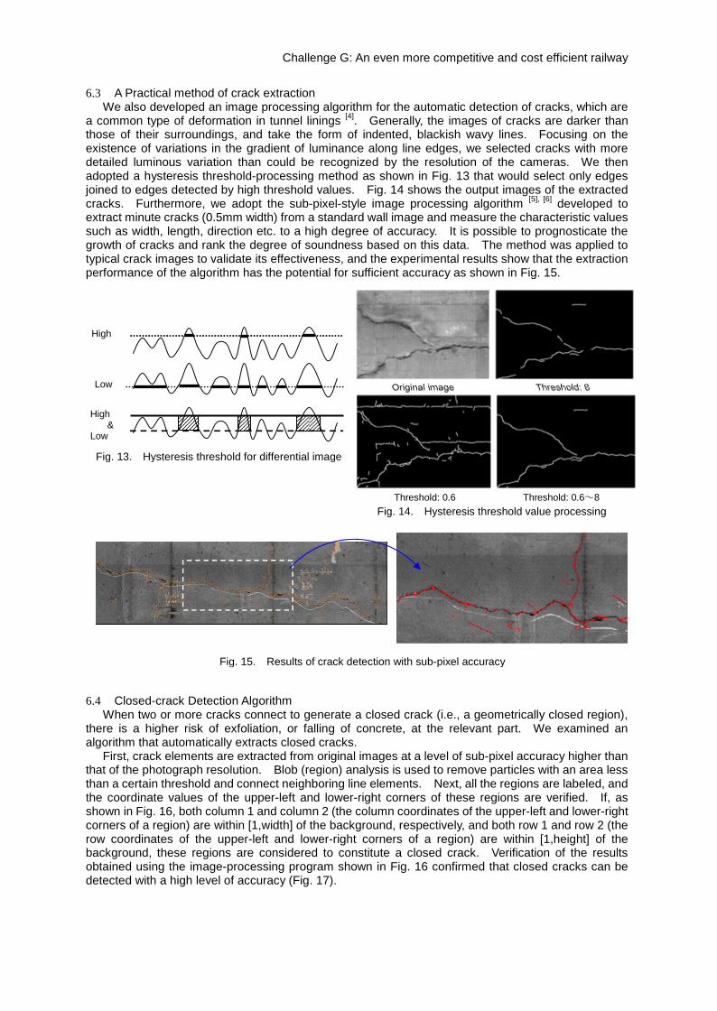
6.3 A Practical method of crack extractionWe also developed an image processing algorithm for the automatic detection of cracks, which are
a common type of deformation in tunnel linings [4]. Generally, the images of cracks are darker thanthose of their surroundings, and take the form of indented, blackish wavy lines. Focusing on theexistence of variations in the gradient of luminance along line edges, we selected cracks with moredetailed luminous variation than could be recognized by the resolution of the cameras. We thenadopted a hysteresis threshold-processing method as shown in Fig. 13 that would select only edgesjoined to edges detected by high threshold values. Fig. 14 shows the output images of the extractedcracks. Furthermore, we adopt the sub-pixel-style image processing algorithm [5], [6] developed toextract minute cracks (0.5mm width) from a standard wall image and measure the characteristic valuessuch as width, length, direction etc. to a high degree of accuracy. It is possible to prognosticate thegrowth of cracks and rank the degree of soundness based on this data. The method was applied totypical crack images to validate its effectiveness, and the experimental results show that the extractionperformance of the algorithm has the potential for sufficient accuracy as shown in Fig. 15.
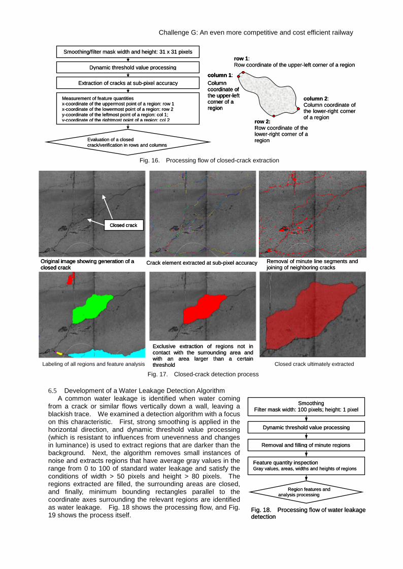
6.4 Closed-crack Detection AlgorithmWhen two or more cracks connect to generate a closed crack (i.e., a geometrically closed region),
there is a higher risk of exfoliation, or falling of concrete, at the relevant part. We examined analgorithm that automatically extracts closed cracks.
First, crack elements are extracted from original images at a level of sub-pixel accuracy higher thanthat of the photograph resolution. Blob (region) analysis is used to remove particles with an area lessthan a certain threshold and connect neighboring line elements. Next, all the regions are labeled, andthe coordinate values of the upper-left and lower-right corners of these regions are verified. If, asshown in Fig. 16, both column 1 and column 2 (the column coordinates of the upper-left and lower-rightcorners of a region) are within [1,width] of the background, respectively, and both row 1 and row 2 (therow coordinates of the upper-left and lower-right corners of a region) are within [1,height] of thebackground, these regions are considered to constitute a closed crack. Verification of the resultsobtained using the image-processing program shown in Fig. 16 confirmed that closed cracks can bedetected with a high level of accuracy (Fig. 17).
High&
Low
High
Low
Fig. 13. Hysteresis threshold for differential image
Fig. 15. Results of crack detection with sub-pixel accuracy
Original image Threshold: 8
Threshold: 0.6 Threshold: 0.6~8Fig. 14. Hysteresis threshold value processing
Challenge G: An even more competitive and cost efficient railway
6.5 Development of a Water Leakage Detection AlgorithmA common water leakage is identified when water coming
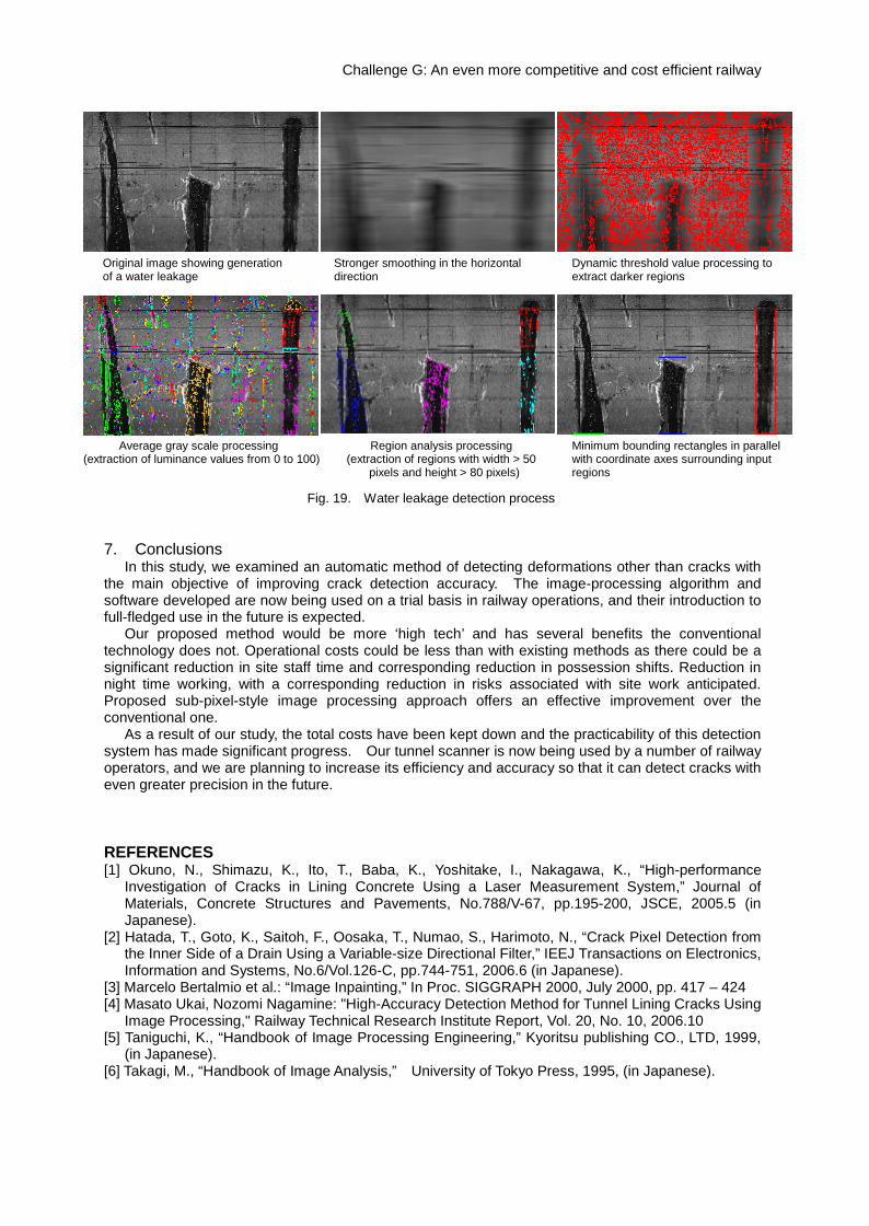
from a crack or similar flows vertically down a wall, leaving ablackish trace. We examined a detection algorithm with a focuson this characteristic. First, strong smoothing is applied in thehorizontal direction, and dynamic threshold value processing(which is resistant to influences from unevenness and changesin luminance) is used to extract regions that are darker than thebackground. Next, the algorithm removes small instances ofnoise and extracts regions that have average gray values in therange from 0 to 100 of standard water leakage and satisfy theconditions of width > 50 pixels and height > 80 pixels. Theregions extracted are filled, the surrounding areas are closed,and finally, minimum bounding rectangles parallel to thecoordinate axes surrounding the relevant regions are identifiedas water leakage. Fig. 18 shows the processing flow, and Fig.19 shows the process itself.
Fig. 17. Closed-crack detection process
Crack element extracted at sub-pixel accuracy
Labeling of all regions and feature analysis Closed crack ultimately extracted
Closed crack
Exclusive extraction of regions not incontact with the surrounding area andwith an area larger than a certainthreshold
Original image showing generation of aclosed crack
Removal of minute line segments andjoining of neighboring cracks
Fig. 16. Processing flow of closed-crack extraction
Smoothing/filter mask width and height: 31 x 31 pixels
Measurement of feature quantitiesx-coordinate of the uppermost point of a region: row 1x-coordinate of the lowermost point of a region: row 2y-coordinate of the leftmost point of a region: col 1;y-coordinate of the rightmost point of a region: col 2
Evaluation of a closedcrack/verification in rows and columns
Dynamic threshold value processing
Extraction of cracks at sub-pixel accuracy
row 1:Row coordinate of the upper-left corner of a region
row 2:Row coordinate of thelower-right corner of aregion
column 1:Columncoordinate ofthe upper-leftcorner of aregion
column 2:Column coordinate ofthe lower-right cornerof a region
Fig. 18. Processing flow of water leakagedetection
SmoothingFilter mask width: 100 pixels; height: 1 pixel
Feature quantity inspectionGray values, areas, widths and heights of regions
Region features andanalysis processing
Dynamic threshold value processing
Removal and filling of minute regions
Challenge G: An even more competitive and cost efficient railway
6.5 Development of a Water Leakage Detection AlgorithmA common water leakage is identified when water coming
from a crack or similar flows vertically down a wall, leaving ablackish trace. We examined a detection algorithm with a focuson this characteristic. First, strong smoothing is applied in thehorizontal direction, and dynamic threshold value processing(which is resistant to influences from unevenness and changesin luminance) is used to extract regions that are darker than thebackground. Next, the algorithm removes small instances ofnoise and extracts regions that have average gray values in therange from 0 to 100 of standard water leakage and satisfy theconditions of width > 50 pixels and height > 80 pixels. Theregions extracted are filled, the surrounding areas are closed,and finally, minimum bounding rectangles parallel to thecoordinate axes surrounding the relevant regions are identifiedas water leakage. Fig. 18 shows the processing flow, and Fig.19 shows the process itself.
Fig. 17. Closed-crack detection process
Crack element extracted at sub-pixel accuracy
Labeling of all regions and feature analysis Closed crack ultimately extracted
Closed crack
Exclusive extraction of regions not incontact with the surrounding area andwith an area larger than a certainthreshold
Original image showing generation of aclosed crack
Removal of minute line segments andjoining of neighboring cracks
Fig. 16. Processing flow of closed-crack extraction
Smoothing/filter mask width and height: 31 x 31 pixels
Measurement of feature quantitiesx-coordinate of the uppermost point of a region: row 1x-coordinate of the lowermost point of a region: row 2y-coordinate of the leftmost point of a region: col 1;y-coordinate of the rightmost point of a region: col 2
Evaluation of a closedcrack/verification in rows and columns
Dynamic threshold value processing
Extraction of cracks at sub-pixel accuracy
row 1:Row coordinate of the upper-left corner of a region
row 2:Row coordinate of thelower-right corner of aregion
column 1:Columncoordinate ofthe upper-leftcorner of aregion
column 2:Column coordinate ofthe lower-right cornerof a region
Fig. 18. Processing flow of water leakagedetection
SmoothingFilter mask width: 100 pixels; height: 1 pixel
Feature quantity inspectionGray values, areas, widths and heights of regions
Region features andanalysis processing
Dynamic threshold value processing
Removal and filling of minute regions
Challenge G: An even more competitive and cost efficient railway
7. ConclusionsIn this study, we examined an automatic method of detecting deformations other than cracks with
the main objective of improving crack detection accuracy. The image-processing algorithm andsoftware developed are now being used on a trial basis in railway operations, and their introduction tofull-fledged use in the future is expected.
Our proposed method would be more ‘high tech’ and has several benefits the conventionaltechnology does not. Operational costs could be less than with existing methods as there could be asignificant reduction in site staff time and corresponding reduction in possession shifts. Reduction innight time working, with a corresponding reduction in risks associated with site work anticipated.Proposed sub-pixel-style image processing approach offers an effective improvement over theconventional one.
As a result of our study, the total costs have been kept down and the practicability of this detectionsystem has made significant progress. Our tunnel scanner is now being used by a number of railwayoperators, and we are planning to increase its efficiency and accuracy so that it can detect cracks witheven greater precision in the future.
REFERENCES[1] Okuno, N., Shimazu, K., Ito, T., Baba, K., Yoshitake, I., Nakagawa, K., “High-performance
Investigation of Cracks in Lining Concrete Using a Laser Measurement System,” Journal ofMaterials, Concrete Structures and Pavements, No.788/V-67, pp.195-200, JSCE, 2005.5 (inJapanese).
[2] Hatada, T., Goto, K., Saitoh, F., Oosaka, T., Numao, S., Harimoto, N., “Crack Pixel Detection fromthe Inner Side of a Drain Using a Variable-size Directional Filter,” IEEJ Transactions on Electronics,Information and Systems, No.6/Vol.126-C, pp.744-751, 2006.6 (in Japanese).
[3] Marcelo Bertalmio et al.: “Image Inpainting,” In Proc. SIGGRAPH 2000, July 2000, pp. 417 – 424[4] Masato Ukai, Nozomi Nagamine: "High-Accuracy Detection Method for Tunnel Lining Cracks Using
Image Processing," Railway Technical Research Institute Report, Vol. 20, No. 10, 2006.10[5] Taniguchi, K., “Handbook of Image Processing Engineering,” Kyoritsu publishing CO., LTD, 1999,
(in Japanese).[6] Takagi, M., “Handbook of Image Analysis,” University of Tokyo Press, 1995, (in Japanese).
Average gray scale processing(extraction of luminance values from 0 to 100)
Region analysis processing(extraction of regions with width > 50
pixels and height > 80 pixels)
Minimum bounding rectangles in parallelwith coordinate axes surrounding inputregions
Original image showing generationof a water leakage
Stronger smoothing in the horizontaldirection
Dynamic threshold value processing toextract darker regions
Fig. 19. Water leakage detection process