Embed Size (px)
Citation preview

1
A High PerformanceEmbedded Machine Tool Controller
William D. Allen
Robert J. Fornaro
Kenneth P. Garrard
Lauren W. Taylor
Precision Engineering Center
North Carolina State University
P.O. Box 7918
Raleigh, NC 27695-7918
2
ABSTRACT
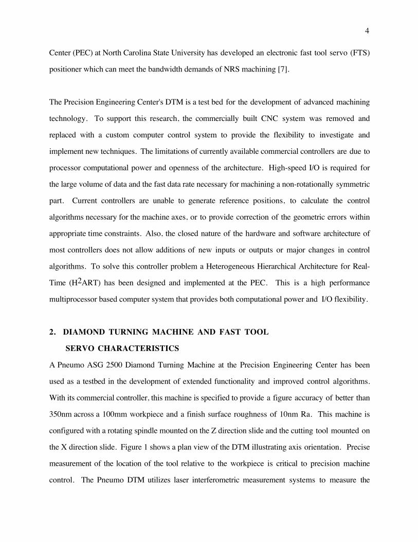
A Diamond Turning Machine (DTM) can fabricate components with extremely high precision
and high quality surface finish characteristics. Existing commercial controllers are limited in
their ability to support high performance machining and related advanced control algorithms.
Evolving enhancements to the functional capability and control algorithms of a DTM require
increased performance and flexibility from the computer system controlling it. To provide
this capability the Precision Engineering Center at North Carolina State University has
developed and implemented a high performance control system for such a machine tool The
control system is based on a heterogeneous hierarchical multiprocessor computer architecture.
This provides the capacity to apply advanced control concepts to the DTM, resulting in
improved precision and quality of machined parts. Additionally, the ability to machine non-
rotationally symmetric components has been made possible by application of multiprocessor
capability.
Keywords:
computer control, multiprocessing systems, precision machining, real-time computer systems

3
1. INTRODUCTION
High precision machining has become increasingly important to manufacturing and the world
economy. Common consumer items such as video cassette recorders and compact disk players
contain components machined to tolerances which were once found only on research and military
equipment. The increasing need for commercial production of high precision items has challenged
precision manufacturing capabilities. In response, new technologies must be developed and
advanced in order to machine more difficult materials and geometries both accurately and
efficiently.
Optical manufacturing is one area which demands extremely high precision. Traditionally, optical
manufacturing techniques involved a grinding process to establish the desired shape followed by a
polishing process to achieve the required surface qualities. This two step process is time
consuming and form accuracy is diminished in the polishing process. A Diamond Turning
Machine (DTM) is an ultraprecision computer numerically controlled (CNC) lathe. The cutting tool
is a highly polished single point diamond tool. The technique of machining, in a single step,
optical quality surfaces on a diamond turning machine (DTM) has revolutionized the fabrication of
reflective and transmissive optical components. This technique also frees the optical designer from
the constraints of spherical shapes and provides a method of integrating the optical surface into the
mechanical structure.
A typical DTM configuration consists of two orthogonally configured precision slideways along
which the cutting tool and/or workpiece move. The workpiece is mounted to a rotating spindle.
Like other turning techniques, diamond turning produces surfaces of revolution, that is surfaces
which do not vary as a function of rotation. Production of surfaces which are non-rotationally
symmetric (NRS) require the means to move the cutting tool in a direction normal to the plane of
the surface as the workpiece rotates. Machining of NRS surfaces has been limited by the physical
bandwidth of the mechanical positioning systems of existing DTMs. The Precision Engineering
4
Center (PEC) at North Carolina State University has developed an electronic fast tool servo (FTS)
positioner which can meet the bandwidth demands of NRS machining [7].
The Precision Engineering Center's DTM is a test bed for the development of advanced machining
technology. To support this research, the commercially built CNC system was removed and
replaced with a custom computer control system to provide the flexibility to investigate and
implement new techniques. The limitations of currently available commercial controllers are due to
processor computational power and openness of the architecture. High-speed I/O is required for
the large volume of data and the fast data rate necessary for machining a non-rotationally symmetric
part. Current controllers are unable to generate reference positions, to calculate the control
algorithms necessary for the machine axes, or to provide correction of the geometric errors within
appropriate time constraints. Also, the closed nature of the hardware and software architecture of
most controllers does not allow additions of new inputs or outputs or major changes in control
algorithms. To solve this controller problem a Heterogeneous Hierarchical Architecture for Real-
Time (H2ART) has been designed and implemented at the PEC. This is a high performance
multiprocessor based computer system that provides both computational power and I/O flexibility.
2. DIAMOND TURNING MACHINE AND FAST TOOL
SERVO CHARACTERISTICS
A Pneumo ASG 2500 Diamond Turning Machine at the Precision Engineering Center has been
used as a testbed in the development of extended functionality and improved control algorithms.
With its commercial controller, this machine is specified to provide a figure accuracy of better than
350nm across a 100mm workpiece and a finish surface roughness of 10nm Ra. This machine is
configured with a rotating spindle mounted on the Z direction slide and the cutting tool mounted on
the X direction slide. Figure 1 shows a plan view of the DTM illustrating axis orientation. Precise
measurement of the location of the tool relative to the workpiece is critical to precision machine
control. The Pneumo DTM utilizes laser interferometric measurement systems to measure the

5
position of the X and Z slides to a resolution of 2.5nm. For the machining of NRS parts, the
rotational position of the spindle must be known as well as tool position. An optical encoder
attached to the spindle generates 4096 pulses per revolution giving a resolution better than 0.1
degree (.0015 rad) of rotational position. Also depicted in Figure 1, is the FTS axis which is
referred to as Z'. The FTS is a piezoelectric actuator capable of moving the cutting tool normal to
the workpiece surface at a high frequency. Typical bandwidths of FTS devices are 100Hz to
2KHz and displacement ranges are .1mm to .025mm. The position of the FTS actuator is
measured by a capacitance gage with resolutions ranging from 25nm to 10nm.
Z Slide Motion
Z' Tool Motion (FTS)
Spindle
Machined Surface
X Slide Motion
Figure 1: DTM / FTS Axis Orientation
3. COMPUTER CONTROL FOR A DIAMOND TURNING MACHINE
Commercial control systems supplied with a DTM are generally standard CNC (computer
numerical control) systems intended for application to a wide variety of machine tools. As such,
they have limited features and capabilities needed for a high performance ultraprecision research
system. These CNC controllers generally have control cycle times of 5-10ms (100-200Hz) and
they incorporate a single algorithm, usually PID, for dynamic control of the machine. For
development of high-precision machine control, the control system must be capable of much higher
control cycle rates (1-10KHz) and have the flexibility to incorporate complex control algorithms.
The computer control system must also have the capability to acquire experimental measurements

6
from the machining process to assist in evaluating and refining control strategies. Both open and
closed loop performance monitoring of axes response with data filtering and adjustable sample
rates will provide these measurements. Data archive facilities must not interfere with the controller
update cycle. This data archiving capability can be utilized in the development of the machine error
budget as well as control algorithms. Additionally, the ability to easily expand and modify the
control system to incorporate new control algorithms and to accommodate new measurement and
actuation devices is required.
3.1 DTM / FTS Control Tasks
There are three major functional elements of a control system for a DTM: user interface, reference
signal generation and axis control. The user interface provides the user with the means to direct
and monitor the operation of the DTM during a machining operation. The reference signal
generation calculates the paths that the tool and workpiece must follow to create the desired shape.
The axis control moves the tool and workpiece during machining to follow the path defined by the
reference signal.
User Interface: Machine operation is initiated by the user through a set of keyboard commands
or via menu selection. These commands include facilities for multi-step part program
interpretation. DTM status is continuously displayed in real-time on a color video monitor with
separate windows reserved for axes position and velocity updates, error messages, part program
status information, and user command scrolling. Extensive command line editing, history, and
recall functions are available. These single line editing functions allow sequences of commands to
be easily repeated with a minimum of keystrokes by the user. They also allow the user to view old
commands that have scrolled off the screen.
The DTM controller software provides a foundation for the further development of control
algorithms. Several control schemes other than PID have been implemented to control the DTM

7
slides. These include discrete lag compensation, butterworth filtering and force feedback control.
A uniform sum of products structure is used for the calculations of each control law. Switching
control types requires down-loading new constants to the control law calculation procedure.
Commands are available to select the control type and the gain constants independently for each
axis. The axes gains can be entered at the command line or read from an input file. To aid in the
system identification and controller evaluation tasks, two additional control programs are provided.
One uses an input file containing an arbitrary signal as the reference input for the type of control
currently selected. The other program accepts a similar input file but uses the data as the open loop
output to each axis. Data recorded by these programs can be used to determine the open and closed
loop response of the DTM to any input signal.
The fundamental control loop timing can also be set by the user. The range of permissible values
is 0.5ms to 25ms. A probe output is also available to test the accuracy of the controller timing. A
software biasing command reduces the frequency of machine adjustments to correct for drift in the
digital-to-analog converters (DACs). A checkpoint/restart facility allows machine setup parameters
and operator preferences to be saved and restored from disk. This allows the recovery of tool
position information in the event of system failure. It also simplifies resetting the controller to its
normal operating mode after completion of software or machine testing. The absolute range of
axes motion can be restricted with operator commands. This provides additional security during
control algorithm testing and for cutting applications that require complex fixturing (e.g.,
grinding).
A batch file execution feature allows long sequences of commands to be executed without the
presence of an operator. This has proved useful for machine control and cutting experiments that
require many iterations of the same axis motion with different parameters and for lengthy data
collection activities (e.g., spindle growth tests over 36 hours). A delay feature allows tests to be

8
conducted after the operator has left the room, thus eliminating one significant environmental
effect.
Reference Surface Generation Algorithms: One of the basic computational problems
encountered in implementing a machine tool controller is the precise description of the desired part
surface in a form appropriate for computer input. This surface description is then translated into a
tool path for the target machine axes orientation. The detailed tool path is used as the reference
input to the closed loop control algorithm. Any defects in this reference signal will be realized in
the resulting machined surface. For the high-precision machining of complex geometries, the
number of components (i.e., part program blocks) in the desired tool path may be prohibitively
large for off-line calculation and on-line storage while machining. This naturally leads to the
notion of on-the-fly reference signal generation. For a FTS, the reference position is itself a
function of two independent feedback inputs and cannot be calculated off-line.
All symmetric reference surfaces (linear and non-linear) can be generated using a parametric
representation of the appropriate mathematical equations. The reference signal generation
algorithms for non-linear surfaces utilize parametric forms of the standard conic equations. These
parametric forms have three advantages for interpolation algorithms. The specific equations
chosen are optimal in that straight lines connecting the generated points will inscribe a polygon of
maximal area under the desired curve. Tool correction formulas are conveniently expressed in
terms of the parametric variable, which is incremented by a constant on each iteration of the
algorithm. This leads to simplification of the tool correction formula. The fundamental,
unsimplified form of the parametric equations also allows reference signal generation to be
performed independently for each axis.
FTS Reference Surface Generation: The machining of non-rotationally symmetric
workpieces using the fast tool servo system presents a significant computational load which

9
requires the use of a dedicated processor to control the tool servo. One application for this
capability is the machining of off-axis conic sections. These can be segments of a mirror too large
to machine as a single element.
The decomposition of the general aspheric optics equation into rotationally symmetric and non-
rotationally symmetric components suitable for on-axis FTS machining of off-axis conic segments
has been described [4,5]. This solution minimizes the range of motion required of the FTS by
tilting the workpiece. The best fit asphere can be generated off-line as a sequence of cords. The
number of cords can be adjusted to obtain any accuracy required in the asphere approximation. A
high-speed axes control processor could also be used to generate the asphere on-the-fly.
The derivation of the surface equations and the method of dividing the total surface into symmetric
and non-symmetric components is discussed below. The general equation of an optical surface of
revolution about the Z axis can be written as [6]
z = cs2
1 + 1 - (k+1) c2s2 + a1s4 + a2s6 + a3s8 + a4s10 + (1)
where
s2 = x2 + y2 and c = 1r = 1radius of curvature
The aspheric deformation constants (ai) will be assumed to be zero so that the surface is a conic
surface of revolution. The constant k is related to the eccentricity (e) of the conic (k = -e2) and
defines its shape.
The geometry of the off-axis segment and its orientation in the parent coordinate system is shown
in Figure 2. Fabrication of a segment of this surface by on-axis machining requires three
coordinate transformations (translation, rotation and transformation to a cylindrical system) to
produce the equation for the surface as a function of the radius and the angle of rotation of the
spindle. These transformations have been published by Gerchman [4] and the resulting equation
for on-axis fabrication of a general conic surface of revolution is

10
z = d1 + d2ρ cos(θ) - d3 + d4ρ cos(θ) + d5ρ2 + d6ρ2 cos2(θ)
(2)
x'
y'
z'
α
z
y
xx0
z 0
Figure 2. Geometry of Off-Axis Segment in Framework of Parent Conic [4].
Equation (2) gives the value of Z as a function of the radius from the spindle axis (ρρρρ) and the
rotational angle (θθθθ) of the spindle. It consists of both a rotationally symmetric component and a
non-rotationally symmetric component. The constants (di) in Equation (2) depend upon the conic
constant, k, the off-axis translation parameters (x0, z0) and the angle of tilt (αααα) of the surface. The
initial selection of the tilt angle is the tangent angle of the parent conic at the center of the segment.
An iterative approximation technique is used to find the angle that minimizes the excursion of the
fast tool servo. Once an acceptable value for αααα is determined the two components of the surface
shape can be written as variations of Equation (2). The rotationally symmetric part will be the
value of Z at θθθθ = ππππ/2, and the non-rotationally symmetric part will be the difference between the
value of Z from Equation (2) and the rotationally symmetric part.

11
The evaluation of Equation (2) using 32-bit floating-point arithmetic may give incorrect results due
to the subtraction of two large but nearly equal quantities. A further simplification is possible that
solves this loss of precision problem. It also reduces the evaluation time of the function by
approximating the square root operation with a polynomial expansion. The final simplified form of
Equation (2) becomes [3]
z = d2ρ cos(θ) - d1 12
E - 18
E2 + 116
E3 - 5128
E4 +
(3)
where E is given by
E = d4d3
ρ cos(θ) + d5d3
ρ2 + d6d3
ρ2 cos2(θ)
(4)
Using Equations (3) and (4) the integrated FTS controller calculates the Z axis reference position
(as a function of the current ρρρρ and θθθθ) in real-time and subtracts the current Z axis position to obtain
the small perturbation component Z’. Using the actual axes positions in the reference calculation
allows the FTS controller to compensate for high-frequency Z axis vibrations as well as the low-
frequency positioning error of the slower DTM axes controller.
Multi-Step Part Program Interpretation: The complete sequence of machine axis
movements required to produce a surface is processed by the part program translator before
execution. Constraint testing and tool path verification operations are performed during the
translation of an ASCII part description file into an internal format suitable for interpretation. Each
movement command in this file (e.g., line, arc) is converted into one or more program blocks that
drive the interpretation process. The blocks contain all relevant geometric parameters as well as
pointers to block setup and next setpoint functions. In this way complex and time
consuming initialization operations can be performed off-line before initiating machine operation.
12
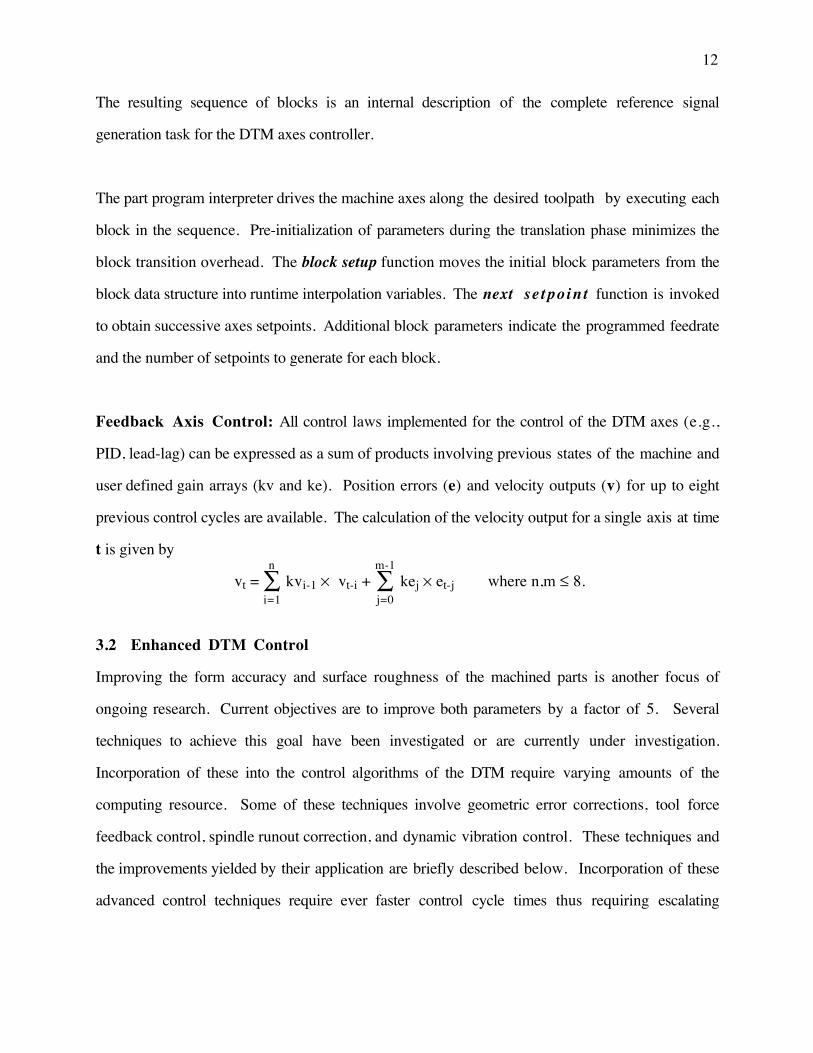
The resulting sequence of blocks is an internal description of the complete reference signal
generation task for the DTM axes controller.
The part program interpreter drives the machine axes along the desired toolpath by executing each
block in the sequence. Pre-initialization of parameters during the translation phase minimizes the
block transition overhead. The block setup function moves the initial block parameters from the
block data structure into runtime interpolation variables. The next se tpoint function is invoked
to obtain successive axes setpoints. Additional block parameters indicate the programmed feedrate
and the number of setpoints to generate for each block.
Feedback Axis Control: All control laws implemented for the control of the DTM axes (e.g.,
PID, lead-lag) can be expressed as a sum of products involving previous states of the machine and
user defined gain arrays (kv and ke). Position errors (e) and velocity outputs (v) for up to eight
previous control cycles are available. The calculation of the velocity output for a single axis at time
t is given by
vt = kvi-1∑i=1
n
× vt-i + kej∑j=0
m-1
× et-j where n,m ≤ 8.
3.2 Enhanced DTM Control
Improving the form accuracy and surface roughness of the machined parts is another focus of
ongoing research. Current objectives are to improve both parameters by a factor of 5. Several
techniques to achieve this goal have been investigated or are currently under investigation.
Incorporation of these into the control algorithms of the DTM require varying amounts of the
computing resource. Some of these techniques involve geometric error corrections, tool force
feedback control, spindle runout correction, and dynamic vibration control. These techniques and
the improvements yielded by their application are briefly described below. Incorporation of these
advanced control techniques require ever faster control cycle times thus requiring escalating

13
computational capability. The H2ART system can evolve seamlessly as computational demands
grow.
Slideway Geometry Correction: Even though the slideways of the DTM are precision
machined, they are not perfectly straight or square. This results in positioning errors in both X and
Z. Furthermore, spindle alignment error results in a yaw of the workpiece as the Z slide is moved.
A straightness errors of ~500nm and a yaw error of up to 2000nm were measured on the PEC
DTM. These errors are repeatable and can be compensated for by the axis control algorithms.
Tool Geometry Compensation: The motion of the tool with respect to the workpiece can be
programmed to follow any prescribed path. However, for non-flat surfaces, the point of contact
between the tool and the workpiece is not constant. The resulting machined surface will have a
slightly different shape from that desired. In most precision machining applications the relative
magnitude of this error is quite large (i.e., on the order of 1 µm). The error induced by the tool is
dependent on both the programmed surface and the tool parameters (usually an ellipsiod with some
surface waviness). The characterization of the tool is in fact an approximation and of course the
tool wears during machining and thus its shape is dynamic. The known errors in the tool can be
used to modify the reference signal so the point of contact is on the desired curve.
Slide Vibration Control: As with any mechanical system, there are vibrations created in the
DTM during machining which may adversely affect surface finish. Control algorithms which
compensate for and reduce these vibrational effects are being developed.
Spindle Runout Compensation: Though it runs in precision bearings, the DTM spindle
exhibits both axial and radial runout. Dynamic measurement of and correction for spindle runout
will require fast (~10KHz) control loops driving a two-axis FTS.

14
Tool Force Feedback Control: Tool forces can be dynamically measured by sensors placed
on the tool holder. Research has indicated that these measurements can be used in the control
algorithms to improve surface finish.
3.3 Control System Partitioning
Development of the Fast Tool Servo (FTS) enhancement for the DTM requires multiple processors
to perform the required control computations. Texas Instruments TMS320C30 floating-point
digital signal processors are used for all control tasks. A custom multiprocessor architecture
provides a platform for maintaining the high I/O and computational throughput needed for a
successful controller implementation.
When considering the partitioning of an integrated control system for multiprocessor
implementation two factors must be considered. First is the logical partitioning of the tasks which
make up the system. This step is generally done along functional lines. Only in situations where
the computational load requires more than one processor will a single control function be split
across more than one processor. After tasks are logically partitioned, the flow of data between
processors must be evaluated. Since a finite amount of time is required to pass data between
processors in a multiprocessor system, the design must insure that data flow capacity and latency
requirements are not exceeded.
An externally acquired data value may be required for the control computation in more than one
processor. Therefore, the point of acquisition of the data and its subsequent distribution to the
remainder of the system must be included in the data flow analysis. In the advanced DTM
controller, the critical external data is the laser position data. This information provides the
reference basis for all control calculations.

15
3.4 DTM Control I/O Requirements
There are a variety of sensor inputs and actuator outputs required to control the DTM. Inputs
consist largely of measurements of the positions of the movable elements of the DTM along with
various signals indicating the machine status. Outputs drive the actuators which position the
slideways and the FTS. The input/output data requirements of each of the control processes are
shown in Table 1. This table reflects only the I/O data required for the existing DTM/FTS control
system. Experimental measurement support as well as additional sensors and actuators require
flexible I/O capabilities. Typical sensor inputs which may be incorporated in the near future
include on-line tool force and spindle runout measurements.
Process Function Analog Digital Input OutputX Axis Controller X and Z Laser Data X X
X Axis Servo Amp X XZ Axis Controller X and Z Laser Data X X
X Axis Servo Amp X XFTS Controller X and Z Laser Data X X
Spindle Encoder X XLR Actuator Laser Data X XCap Gage X XSpindle Amp X XFTS Servo Amp X X
System Controller Home Switches X XManual Jogger X XMachine Faults X XEmergency Stop X X XMachine Functions X X
Table 1: DTM / FTS Process Input / Output Requirements
3.5 DTM Control System
A computer system based on a PEC developed Hierarchical Heterogeneous Architecture for Real-
Time (H2ART) provides the computational power for advanced control algorithms. This
architecture consists of multiple nodes each containing a node controller and one or more
computational processors. To eliminate the bottleneck of having a centralized I/O facility, each
computational processor has its own I/O interface. This allows the computational processors to
function autonomously (except for coordinating data shared by several processors). The H2ART

16
architecture provides a system that is flexible and readily scalable to accommodate future system
growth.
The target for an advanced control system for a DTM is to provide capability for a 2KHz control
rate for X and Z axes and on the order of 10KHz for Z' (FTS) with additional computational
capacity for implementation of advanced control algorithms. Control enhancements include
geometric error correction and slide vibration reduction. Other functional goals include tool force
feedback control, a long range fast tool servo, spindle runout correction, on-line tool wear
compensation, enhanced operator interface and continuous data archiving.
The DTM/FTS control application requires multiple processors. Major decisions in the
implementation of the new control system revolve around how to partition the control application
and how to determine the number of control processors required. A natural partitioning of the
DTM/FTS application is along functional control lines. This application has four major
components: X axis control, Z axis control, FTS control, and system coordination. In the H2ART
based DTM/FTS control system, the integrated application is partitioned and distributed across four
TMS320C30 control processors. Each of the major axes (X, Z) is controlled by a separate
processor. FTS control utilizes a third processor dedicated to that function. The fourth processor
is assigned to coordinating the other three and processing manual operator requests. The 80186
node controllers will manage acquisition of data for archiving and communications with the host
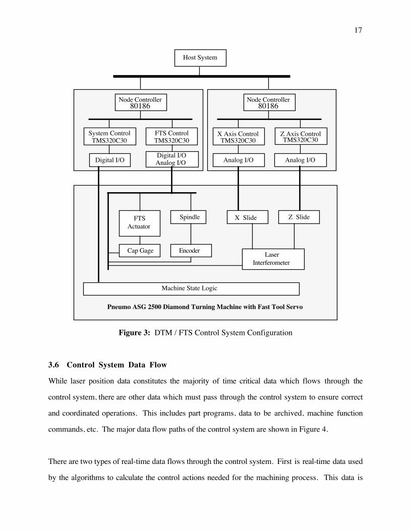
system. Currently, the host computer for the system is a PC-AT. A block diagram of the
DTM/FTS control system is shown in Figure 3. This system will provide the computational power
necessary for supporting the next generation of control strategies for the DTM.
17
Host System
TMS320C30Z Axis ControlX Axis Control
TMS320C30
Analog I/O Analog I/O
Node Controller80186
Node Controller80186
System Control FTS ControlTMS320C30TMS320C30
Digital I/ODigital I/OAnalog I/O
Pneumo ASG 2500 Diamond Turning Machine with Fast Tool Servo
Machine State Logic
LaserInterferometer
FTS Actuator
X Slide Z SlideSpindle
Cap Gage Encoder
Figure 3: DTM / FTS Control System Configuration
3.6 Control System Data Flow
While laser position data constitutes the majority of time critical data which flows through the
control system, there are other data which must pass through the control system to ensure correct
and coordinated operations. This includes part programs, data to be archived, machine function
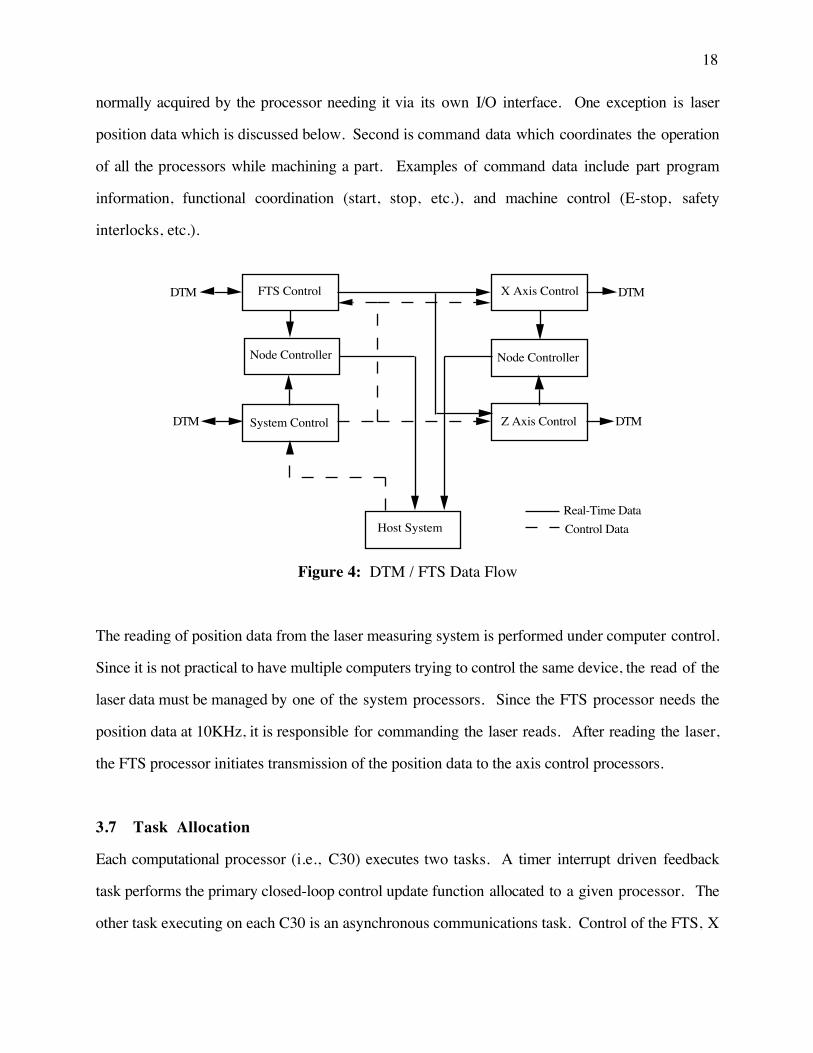
commands, etc. The major data flow paths of the control system are shown in Figure 4.
There are two types of real-time data flows through the control system. First is real-time data used
by the algorithms to calculate the control actions needed for the machining process. This data is
18
normally acquired by the processor needing it via its own I/O interface. One exception is laser
position data which is discussed below. Second is command data which coordinates the operation
of all the processors while machining a part. Examples of command data include part program
information, functional coordination (start, stop, etc.), and machine control (E-stop, safety
interlocks, etc.).
Node Controller
FTS Control X Axis Control
System Control
Node Controller
Z Axis Control
Host SystemReal-Time Data
Control Data
DTM
DTM
DTM
DTM
Figure 4: DTM / FTS Data Flow
The reading of position data from the laser measuring system is performed under computer control.
Since it is not practical to have multiple computers trying to control the same device, the read of the
laser data must be managed by one of the system processors. Since the FTS processor needs the
position data at 10KHz, it is responsible for commanding the laser reads. After reading the laser,
the FTS processor initiates transmission of the position data to the axis control processors.
3.7 Task Allocation
Each computational processor (i.e., C30) executes two tasks. A timer interrupt driven feedback
task performs the primary closed-loop control update function allocated to a given processor. The
other task executing on each C30 is an asynchronous communications task. Control of the FTS, X
19
axis, and Z axis is separately allocated to individual computational processors. These periodic
tasks execute at 10KHz, 2KHz and 2KHz respectively. The system control processor feedback
task is allocated to a fourth computational processor and updates machine state information at a
much slower 10Hz rate.
The system control processor communications task accepts commands from the host, processes
them, and sends the appropriate messages to the control processors. The communications task on
the control processors (FTS and axes) handles the receipt of incoming messages and modifies the
feedback task state accordingly. Since the feedback and communications tasks share critical data a
mutual exclusion mechanism is used to prevent data corruption.
3.8 Real-Time Data Communications
A key design consideration in the implementation of this system is the means of real-time
interprocessor data communications [1]. For example, as noted above, the laser position data must
be transferred from the FTS controller to the axis controllers at a 2KHz rate. Based on an
evaluation of the interprocessor communications performance of a generalized message passing
service in the H2ART architecture, an application specific interprocessor communication service is
required.
In the H2ART architecture concept, message passing is the responsibility of the node controller.
H2ART operating system software includes a generalized interprocessor message passing facility.
This facility provides for all interprocessor data flow in the DTM/FTS control system, except
transfer of laser position data. Communication of laser data requires higher performance than
provided by the generalized message passing facility. The generalized message passing facility
transfers data between computation processors at rates of 1.0µs (intranode) and 2.8µs (internode)
per 16-bit word. Message passing overheads are 276µs and 404µs respectively. Using the
general communication package, the internode transfer of the 64-bit laser position data takes

20
415µs. Thus the overhead makes the latency of the generalized message system too large for
timely transfer of laser position data from the FTS control processor to the X-axis and Z-axis
controllers. Reducing the communications overhead reduces the latency between feedback inputs
and calculated control outputs [2].
Implementation of a virtual circuit facility for frequent transfers was considered and discarded due
to estimated intranode and internode overheads of 125µs and 250µs respectively. To provide the
higher interprocessor communication speeds desired for the FTS control, the serial I/O ports of the
C30 were used. These ports can transfer data at rates up to 520,000 16-bit words per second. The
two ports on the FTS controller directly connect to the X-axis and Z-axis controllers. Since these
paths are dedicated to transfer of laser position data, the overhead is very low. These direct
interconnections transfer laser position data blocks at a rate of 8.0µs per block.
4. CONCLUSION
The scalable, open features of the Heterogeneous Hierarchical Architecture for Real-Time permit
the design and implementation of advanced, high-performance control system strategies. The
Diamond Turning Machine with the Fast Tool Servo enhancement is a unique system with
demanding computational requirements. A prototype has been implemented that demonstrates
ultraprecision capability in an important manufacturing area. Also, the stage has been set for
continued improvement in manufacturing quality and precision.

21
REFERENCES
[1] W.D. Allen and R.J. Fornaro, Interprocessor Communications Performance in H2ART
Multiprocessor Computer Systems, Precision Engineering Center 1992 Annual Report, Vol.
X (1993) 237-250.
[2] John G. Bollinger and N. A. Duffie, Computer Control of Machines and Processes,
(Addison-Wesley, Reading, MA, 1988).
[3] K.P. Garrard and R.J. Fornaro, Diamond Turning Machine Controller Software
Development, Precision Engineering Center 1991 Annual Report, Vol. IX (1992) 279-289.
[4] M.C. Gerchman, A Description of Off-Axis Conic Surfaces for Non-Axisymmetric
Generation, SPIE Proceedings, Vol. 1266 (1990).
[5] D.E. Luttrell, Machining Non-Axisymmetric Optics, Proceedings from ASPE Annual
Conference, (1990) 31-34.
[6] Daniel Malacara, Optical Shop Testing, (John Wiley and Sons, New York, 1978).
[7] M.H. Miller, K.P. Garrard, T.A. Dow, and L.W. Taylor, Controller Design for a Modern
Diamond Turning Machine, Proceedings from ASPE Annual Conference, (1991) 62-65.