Embed Size (px)
Citation preview
1
A Hewlett Packard Infrared Signal Decoder
Martin Hepperle
June 2015 – November 2017
Several Hewlett Packard pocket calculators are able to send printer output via Infra-Red (IR) signals to
a small portable printer. They use an HP-specific transmission protocol which is also called “Red
Eye”. This protocol is different from the better known IrDA protocol. This document gives a brief
overview of the format and describes hard- and software to build a decoder system for this protocol.
This system allows receiving the “Red Eye” signals with a computer via a serial or an USB interface.
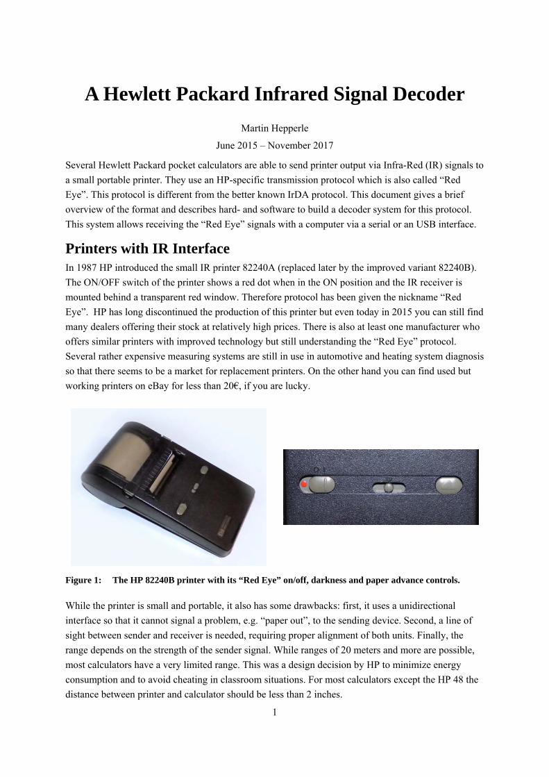
Printers with IR Interface In 1987 HP introduced the small IR printer 82240A (replaced later by the improved variant 82240B).
The ON/OFF switch of the printer shows a red dot when in the ON position and the IR receiver is
mounted behind a transparent red window. Therefore protocol has been given the nickname “Red
Eye”. HP has long discontinued the production of this printer but even today in 2015 you can still find
many dealers offering their stock at relatively high prices. There is also at least one manufacturer who
offers similar printers with improved technology but still understanding the “Red Eye” protocol.
Several rather expensive measuring systems are still in use in automotive and heating system diagnosis
so that there seems to be a market for replacement printers. On the other hand you can find used but
working printers on eBay for less than 20€, if you are lucky.
Figure 1: The HP 82240B printer with its “Red Eye” on/off, darkness and paper advance controls.
While the printer is small and portable, it also has some drawbacks: first, it uses a unidirectional
interface so that it cannot signal a problem, e.g. “paper out”, to the sending device. Second, a line of
sight between sender and receiver is needed, requiring proper alignment of both units. Finally, the
range depends on the strength of the sender signal. While ranges of 20 meters and more are possible,
most calculators have a very limited range. This was a design decision by HP to minimize energy
consumption and to avoid cheating in classroom situations. For most calculators except the HP 48 the
distance between printer and calculator should be less than 2 inches.

2
IR enabled HP Calculators A surprisingly large number of HP calculator models were able to transmit through an IR emitter
diode. A few even included a receiver to allow for bidirectional communication, using the SIR
protocol. At least for the HP 48 some special software is available to receive the “Red Eye” protocol.
HP products HP 17B1 HP 27S HP 41C2 HP 48S1,3
HP 17BII1 HP 28C HP 41CV2 HP 48SX1,3
HP 17BII+1 HP 28S1 HP 41CX2 HP 48G1,3
HP 18C1 HP 42S1 HP 48 GX3
HP 19B HP 95LX3.4 HP 48gII1,3
HP 19BII1 HP 100LX1,3,4 HP 48G+3
HP 200LX3.4 HP 49G+3
HP 50g1,3
almost HP non HP HP 38G1,3
WP 34S calculator1 test equipment HP 39G3
e.g. from TESTO HP 39gs1,3
HP 39g+1
Table 1: HP calculators and other products able to send out IR signals in “Red Eye” format.
Figure 2: While you cannot see the infrared signal
with your naked eye you can detect it
with most digital cameras. Even if they
are equipped with IR filters they show an
active IR LED as a blue light.
1 These calculators have been used to verify the working of the IR decoder application.
2 The HP 41 models require the HP 82242 IR module (dubbed „Blinky“) to enable output in „Red Eye“ format.
3 Besides the output capability these calulators also have infrared input. However this input normally uses the SIR (Serial over Infra Red) protocol which is not „Red Eye“ compatible. For some models (e.g. HP 48G) special software has been written to decode the „Red Eye“ protocol.
4 The HP 95/100/200 LX models by default support SIR and require software to print in “Red Eye” format.
3
Some calculators have no other I/O capabilities than their IR printer interface (except for keyboard and
display of course). For these machines the capability to receive the print stream on a PC is useful for
documenting and archiving programs and data in the PC or on external media.
„Red Eye“Protocol
HP 17HP 28HP 48etc.
HP 17HP 28HP48etc.
HP100LXSoftware:
«IR-Print»
HP82240
Sender
Receiver
HP 48Software
«INPRT»
RS232C USB
ArduinoAVR
Receiver
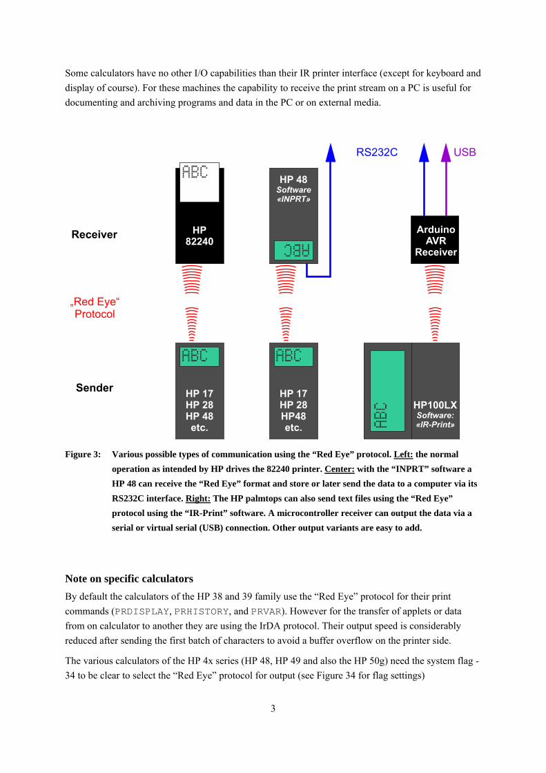
Figure 3: Various possible types of communication using the “Red Eye” protocol. Left: the normal
operation as intended by HP drives the 82240 printer. Center: with the “INPRT” software a
HP 48 can receive the “Red Eye” format and store or later send the data to a computer via its
RS232C interface. Right: The HP palmtops can also send text files using the “Red Eye”
protocol using the “IR-Print” software. A microcontroller receiver can output the data via a
serial or virtual serial (USB) connection. Other output variants are easy to add.
Note on specific calculators
By default the calculators of the HP 38 and 39 family use the “Red Eye” protocol for their print
commands (PRDISPLAY, PRHISTORY, and PRVAR). However for the transfer of applets or data
from on calculator to another they are using the IrDA protocol. Their output speed is considerably
reduced after sending the first batch of characters to avoid a buffer overflow on the printer side.
The various calculators of the HP 4x series (HP 48, HP 49 and also the HP 50g) need the system flag -
34 to be clear to select the “Red Eye” protocol for output (see Figure 34 for flag settings)
4
The IR-Signal The calculators send a byte stream with one byte per data frame. Each data frame contains error
correction bits which allow to correct up to two missed bits. As there is no handshaking involved,
timing can be critical and the HP pocket calculators usually allow the user to define a delay between
sending the bytes or lines. This is especially important with the relatively slow thermal printers HP
82240A/B. Some calculators automatically slow down their output speed when printing multiple lines
to avoid overflowing the printer buffer. For more details about the protocol see the list of references
below.
854.5 sμone bit 7.5 sμ12817.5 sμ
START(1) (2) (3)
EC(1)
EC(2)
EC(3)
EC(4)
D(7)
D(6)
D(5)
D(4)
D(3)
D(2)
D(1)
D(0)
STOP(1) (2) (3)
0 sμ0 sμ
min. 6 cycles = 183 sμmin. 6 cycles = 183 sμ
max. 8 cycles = 244 sμmax. 8 cycles = 244 sμ
1 11
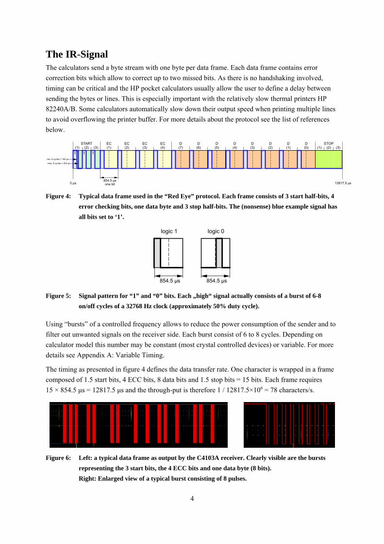
Figure 4: Typical data frame used in the “Red Eye” protocol. Each frame consists of 3 start half-bits, 4
error checking bits, one data byte and 3 stop half-bits. The (nonsense) blue example signal has
all bits set to ‘1’.
logic 0
sμ854.5 sμ
logic 1
sμ854.5 sμ
Figure 5: Signal pattern for “1” and “0” bits. Each „high“ signal actually consists of a burst of 6-8
on/off cycles of a 32768 Hz clock (approximately 50% duty cycle).
Using “bursts” of a controlled frequency allows to reduce the power consumption of the sender and to
filter out unwanted signals on the receiver side. Each burst consist of 6 to 8 cycles. Depending on
calculator model this number may be constant (most crystal controlled devices) or variable. For more
details see Appendix A: Variable Timing.
The timing as presented in figure 4 defines the data transfer rate. One character is wrapped in a frame
composed of 1.5 start bits, 4 ECC bits, 8 data bits and 1.5 stop bits = 15 bits. Each frame requires
15 × 854.5 μs = 12817.5 μs and the through-put is therefore 1 / 12817.5×106 = 78 characters/s.
Figure 6: Left: a typical data frame as output by the C4103A receiver. Clearly visible are the bursts
representing the 3 start bits, the 4 ECC bits and one data byte (8 bits).
Right: Enlarged view of a typical burst consisting of 8 pulses.
5
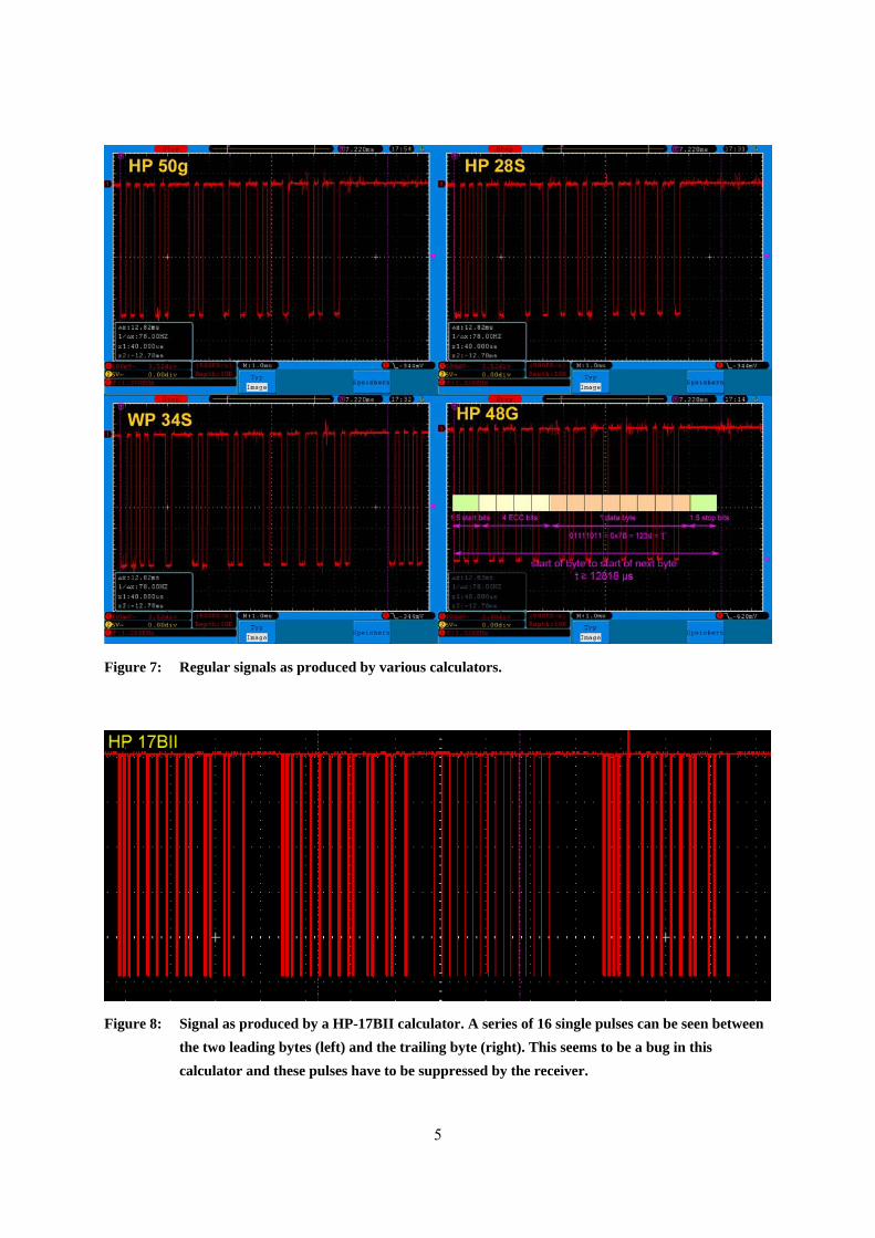
Figure 7: Regular signals as produced by various calculators.
Figure 8: Signal as produced by a HP-17BII calculator. A series of 16 single pulses can be seen between
the two leading bytes (left) and the trailing byte (right). This seems to be a bug in this
calculator and these pulses have to be suppressed by the receiver.
6
The IR-Receiver In principle there are two ways to decode the signal: one could use integrating receiver hardware
which converts each burst into a continuous pulse stretching over the complete duration of the burst or
one could capture the individual pulses of the burst and do the integration by software.
The first approach seems to be straightforward, but requires a receiver chip which can detect the
minimum number of six burst pulses and which must also not extend its output pulse too much beyond
the end of the burst. Only then it would be able to detect the short gap between subsequent bursts, e.g.
between the start half-bits. Most currently available integrating receiver chips are not suited for this
purpose because many cannot detect the shortest bursts of 6 cycles (most are designed for 10 and more
cycles). Also most of them cannot cope with the rather short gaps between the bursts and they are not
able to reliably restart their integration for the next burst. Such receivers then merge the individual
bursts. Types like the Telefunken/Vishay TSOP1133, TSOP1333, TSOP1833, or the more recent
models TSOP4133 or TSOP2133 will not work properly (see appendix).
Therefore I selected the second method to decode the signal. This means that the required IR-receiver
must be fast enough to detect the individual pulses of each burst. One could design such a receiver unit
using an IR phototransistor and an amplifier. Instead I found a (for me) simpler way, using a
commercial IrDA receiver which also provides a nice case.
For maximum range, the design wavelength of the receiver should be close to 940 nm.
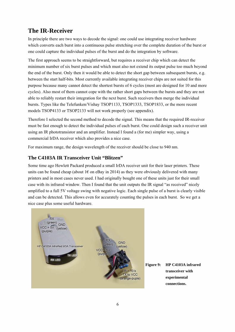
The C4103A IR Transceiver Unit “Blitzen”
Some time ago Hewlett Packard produced a small IrDA receiver unit for their laser printers. These
units can be found cheap (about 1€ on eBay in 2014) as they were obviously delivered with many
printers and in most cases never used. I had originally bought one of these units just for their small
case with its infrared window. Then I found that the unit outputs the IR signal “as received” nicely
amplified to a full 5V voltage swing with negative logic. Each single pulse of a burst is clearly visible
and can be detected. This allows even for accurately counting the pulses in each burst. So we get a
nice case plus some useful hardware.
Figure 9: HP C4103A infrared
transceiver with
experimental
connections.
7
VCC = 5V(purple)
GND(yellow)
RX(green)
+TX(orange)
10k
-TX
HP C4103Alooking onto the connector from the pin side
(not from the wire side)
2.4k RX
GND
VCC
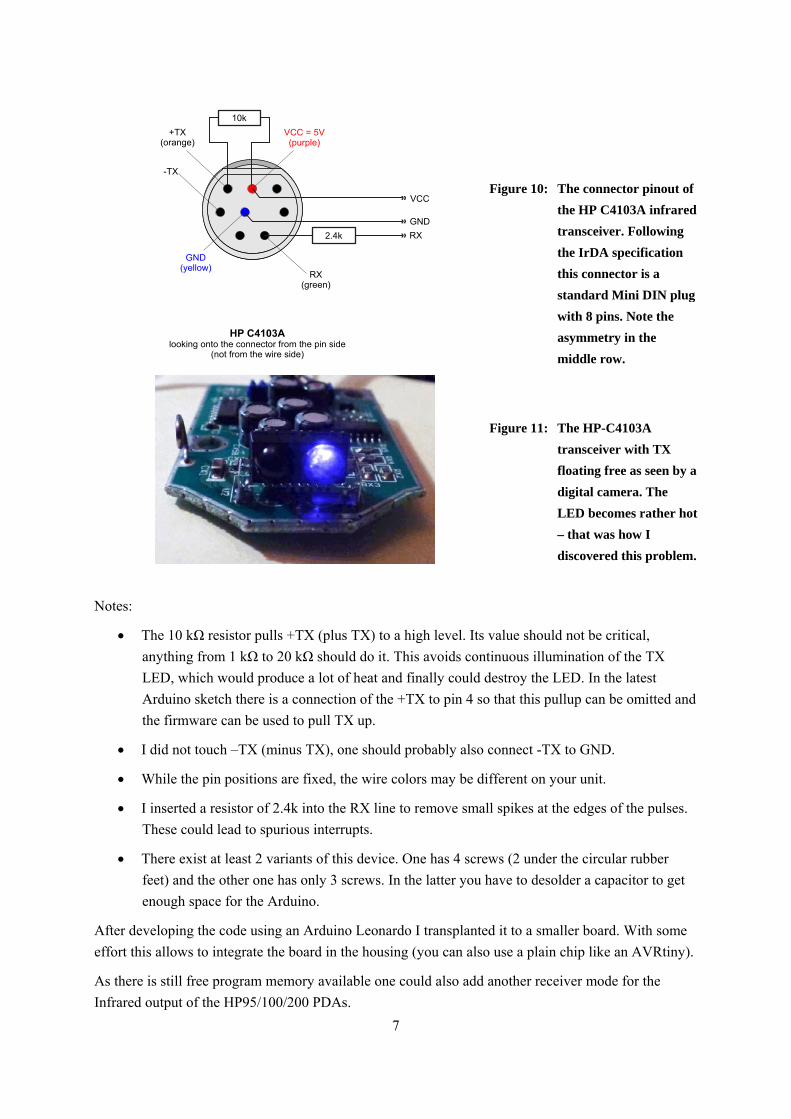
Figure 10: The connector pinout of
the HP C4103A infrared
transceiver. Following
the IrDA specification
this connector is a
standard Mini DIN plug
with 8 pins. Note the
asymmetry in the
middle row.
Figure 11: The HP-C4103A
transceiver with TX
floating free as seen by a
digital camera. The
LED becomes rather hot
– that was how I
discovered this problem.
Notes:
The 10 kΩ resistor pulls +TX (plus TX) to a high level. Its value should not be critical,
anything from 1 kΩ to 20 kΩ should do it. This avoids continuous illumination of the TX
LED, which would produce a lot of heat and finally could destroy the LED. In the latest
Arduino sketch there is a connection of the +TX to pin 4 so that this pullup can be omitted and
the firmware can be used to pull TX up.
I did not touch –TX (minus TX), one should probably also connect -TX to GND.
While the pin positions are fixed, the wire colors may be different on your unit.
I inserted a resistor of 2.4k into the RX line to remove small spikes at the edges of the pulses.
These could lead to spurious interrupts.
There exist at least 2 variants of this device. One has 4 screws (2 under the circular rubber
feet) and the other one has only 3 screws. In the latter you have to desolder a capacitor to get
enough space for the Arduino.
After developing the code using an Arduino Leonardo I transplanted it to a smaller board. With some
effort this allows to integrate the board in the housing (you can also use a plain chip like an AVRtiny).
As there is still free program memory available one could also add another receiver mode for the
Infrared output of the HP95/100/200 PDAs.
8
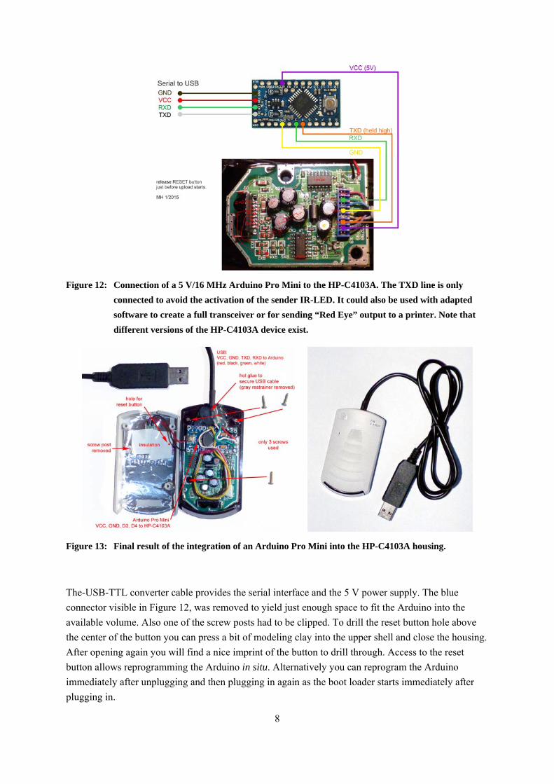
Figure 12: Connection of a 5 V/16 MHz Arduino Pro Mini to the HP-C4103A. The TXD line is only
connected to avoid the activation of the sender IR-LED. It could also be used with adapted
software to create a full transceiver or for sending “Red Eye” output to a printer. Note that
different versions of the HP-C4103A device exist.
Figure 13: Final result of the integration of an Arduino Pro Mini into the HP-C4103A housing.
The-USB-TTL converter cable provides the serial interface and the 5 V power supply. The blue
connector visible in Figure 12, was removed to yield just enough space to fit the Arduino into the
available volume. Also one of the screw posts had to be clipped. To drill the reset button hole above
the center of the button you can press a bit of modeling clay into the upper shell and close the housing.
After opening again you will find a nice imprint of the button to drill through. Access to the reset
button allows reprogramming the Arduino in situ. Alternatively you can reprogram the Arduino
immediately after unplugging and then plugging in again as the boot loader starts immediately after
plugging in.
9
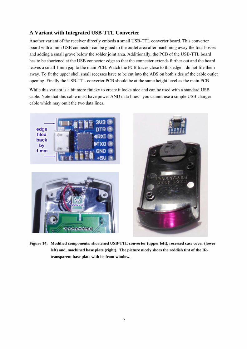
A Variant with Integrated USB-TTL Converter
Another variant of the receiver directly embeds a small USB-TTL converter board. This converter
board with a mini USB connector can be glued to the outlet area after machining away the four bosses
and adding a small grove below the solder joint area. Additionally, the PCB of the USB-TTL board
has to be shortened at the USB connector edge so that the connecter extends further out and the board
leaves a small 1 mm gap to the main PCB. Watch the PCB traces close to this edge – do not file them
away. To fit the upper shell small recesses have to be cut into the ABS on both sides of the cable outlet
opening. Finally the USB-TTL converter PCB should be at the same height level as the main PCB.
While this variant is a bit more finicky to create it looks nice and can be used with a standard USB
cable. Note that this cable must have power AND data lines - you cannot use a simple USB charger
cable which may omit the two data lines.
Figure 14: Modified components: shortened USB-TTL converter (upper left), recessed case cover (lower
left) and, machined base plate (right). The picture nicely shoes the reddish tint of the IR-
transparent base plate with its front window.
10
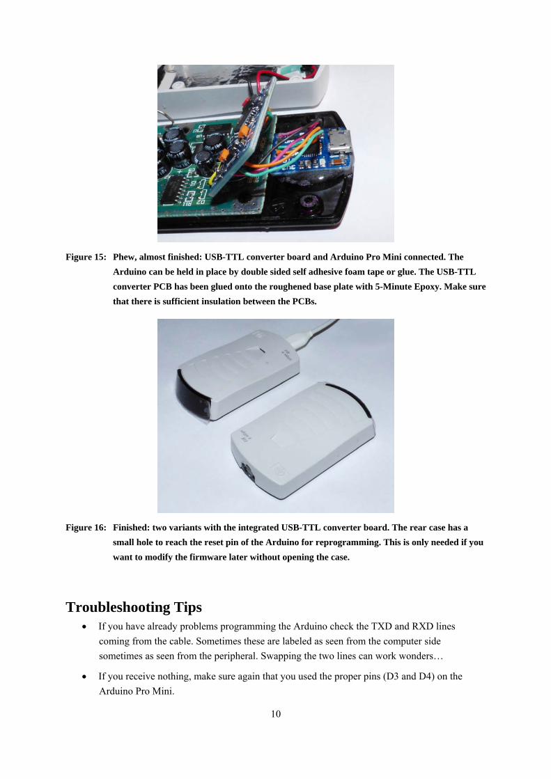
Figure 15: Phew, almost finished: USB-TTL converter board and Arduino Pro Mini connected. The
Arduino can be held in place by double sided self adhesive foam tape or glue. The USB-TTL
converter PCB has been glued onto the roughened base plate with 5-Minute Epoxy. Make sure
that there is sufficient insulation between the PCBs.
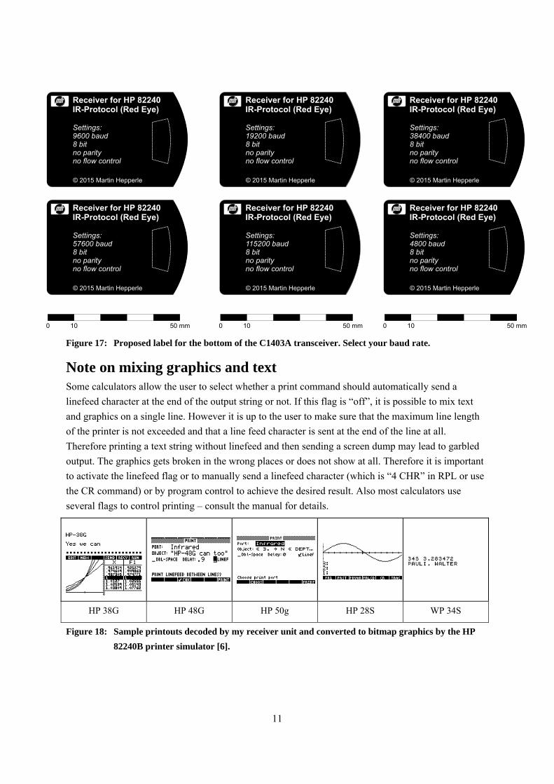
Figure 16: Finished: two variants with the integrated USB-TTL converter board. The rear case has a
small hole to reach the reset pin of the Arduino for reprogramming. This is only needed if you
want to modify the firmware later without opening the case.
Troubleshooting Tips If you have already problems programming the Arduino check the TXD and RXD lines
coming from the cable. Sometimes these are labeled as seen from the computer side
sometimes as seen from the peripheral. Swapping the two lines can work wonders…
If you receive nothing, make sure again that you used the proper pins (D3 and D4) on the
Arduino Pro Mini.
11
Receiver for HP 82240IR-Protocol (Red Eye)
Settings:57600 baud8 bitno parityno flow control
© 2015 Martin Hepperle
0 10 50 mm
Receiver for HP 82240IR-Protocol (Red Eye)
Settings:9600 baud8 bitno parityno flow control
© 2015 Martin Hepperle
Receiver for HP 82240IR-Protocol (Red Eye)
Settings:115200 baud8 bitno parityno flow control
© 2015 Martin Hepperle
0 10 50 mm
Receiver for HP 82240IR-Protocol (Red Eye)
Settings:19200 baud8 bitno parityno flow control
© 2015 Martin Hepperle
Receiver for HP 82240IR-Protocol (Red Eye)
Settings:4800 baud8 bitno parityno flow control
© 2015 Martin Hepperle
0 10 50 mm
Receiver for HP 82240IR-Protocol (Red Eye)
Settings:38400 baud8 bitno parityno flow control
© 2015 Martin Hepperle
Figure 17: Proposed label for the bottom of the C1403A transceiver. Select your baud rate.
Note on mixing graphics and text Some calculators allow the user to select whether a print command should automatically send a
linefeed character at the end of the output string or not. If this flag is “off”, it is possible to mix text
and graphics on a single line. However it is up to the user to make sure that the maximum line length
of the printer is not exceeded and that a line feed character is sent at the end of the line at all.
Therefore printing a text string without linefeed and then sending a screen dump may lead to garbled
output. The graphics gets broken in the wrong places or does not show at all. Therefore it is important
to activate the linefeed flag or to manually send a linefeed character (which is “4 CHR” in RPL or use
the CR command) or by program control to achieve the desired result. Also most calculators use
several flags to control printing – consult the manual for details.
HP 38G HP 48G HP 50g HP 28S WP 34S
Figure 18: Sample printouts decoded by my receiver unit and converted to bitmap graphics by the HP
82240B printer simulator [6].
12
Yet Another Variant Instead of using a USB-TTL serial cable you can also add a RS232-TTL converter like the MAX 232
chip to create a “RedEye” receiver with a standard serial (RS232) port. Such a device is useful if you
like to tinker with other older computers like the HP Series-80 or HP Series-9000. I built one of these
and connected it to my HP Integral PC. A suitable receiver software listens at the serial port and
displays the text as well as the graphics in separate windows.
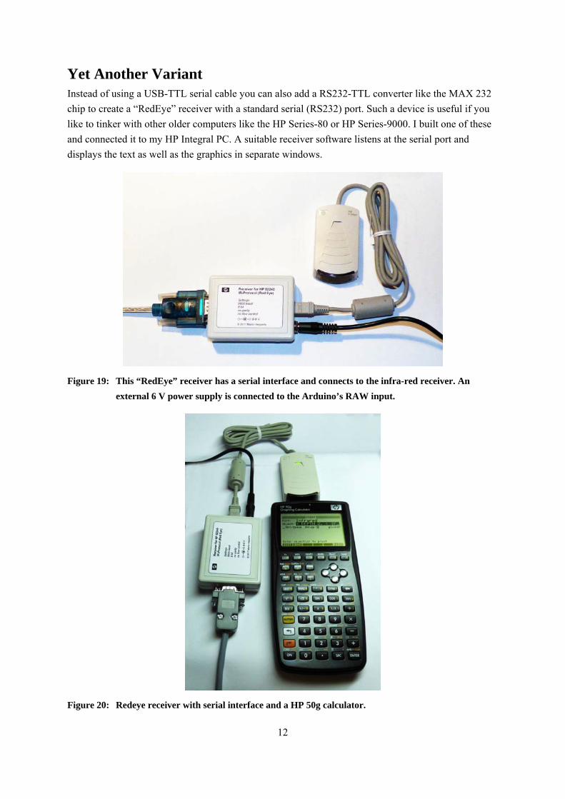
Figure 19: This “RedEye” receiver has a serial interface and connects to the infra-red receiver. An
external 6 V power supply is connected to the Arduino’s RAW input.
Figure 20: Redeye receiver with serial interface and a HP 50g calculator.
13
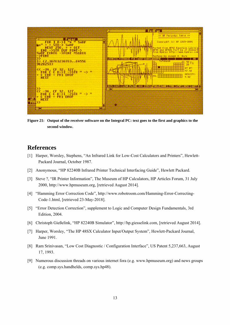
Figure 21: Output of the receiver software on the Integral PC: text goes to the first and graphics to the
second window.
References [1] Harper, Worsley, Stephens, “An Infrared Link for Low-Cost Calculators and Printers”, Hewlett-
Packard Journal, October 1987.
[2] Anonymous, “HP 82240B Infrared Printer Technical Interfacing Guide”, Hewlett Packard.
[3] Steve ?, “IR Printer Information”, The Museum of HP Calculators, HP Articles Forum, 31 July
2000, http://www.hpmuseum.org, [retrieved August 2014].
[4] “Hamming Error Correction Code”, http://www.robotroom.com/Hamming-Error-Correcting-
Code-1.html, [retrieved 23-May-2018].
[5] “Error Detection Correction”, supplement to Logic and Computer Design Fundamentals, 3rd
Edition, 2004.
[6] Christoph Gießelink, “HP 82240B Simulator”, http://hp.giesselink.com, [retrieved August 2014].
[7] Harper, Worsley, “The HP 48SX Calculator Input/Output System”, Hewlett-Packard Journal,
June 1991.
[8] Ram Srinivasan, “Low Cost Diagnostic / Configuration Interface”, US Patent 5,237,663, August
17, 1993.
[9] Numerous discussion threads on various internet fora (e.g. www.hpmuseum.org) and news groups
(e.g. comp.sys.handhelds, comp.sys.hp48).
14
The Arduino Software (“Sketch”) This Arduino sketch can be used to decode the infrared signal sent by a Hewlett Packard pocket
calculator. It was originally developed using an Arduino Leonardo, later transferred easily to an
Arduino Pro Mini. The code decodes the signal and sends the output to a printer simulator or to a
terminal program running on a personal computer. Modified versions can easily be produced to send
output to other devices (displays, printers or storage devices), to translate special characters or to
implement your own control sequences for process control.
Besides the Arduino or a separate AVR chip only a suitable infrared receiver is required. This receiver
must be of the “non-integrating” type, i.e. it must output the individual pulses of each burst.
The sketch contains everything needed to decode the signal. If you want to use other interrupt pins
instead of INT1 or INT6 as already prepared in the header file, you would have to make small
modifications.
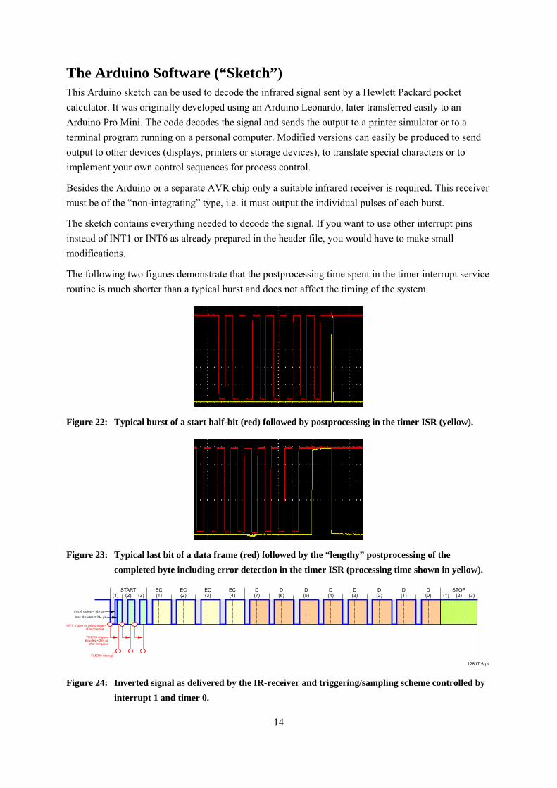
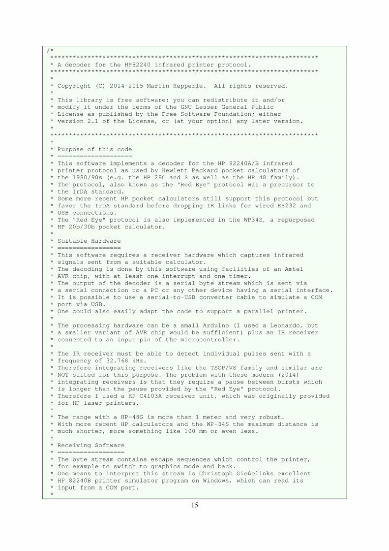
The following two figures demonstrate that the postprocessing time spent in the timer interrupt service
routine is much shorter than a typical burst and does not affect the timing of the system.
Figure 22: Typical burst of a start half-bit (red) followed by postprocessing in the timer ISR (yellow).
Figure 23: Typical last bit of a data frame (red) followed by the “lengthy” postprocessing of the
completed byte including error detection in the timer ISR (processing time shown in yellow).
7.5 sμ12817.5 sμ
TIMER0 elapses8 cycles = 244 sμ
after first pulse
START(1) (2) (3)
EC(1)
EC(2)
EC(3)
EC(4)
D(7)
D(6)
D(5)
D(4)
D(3)
D(2)
D(1)
D(0)
STOP(1) (2) (3)
INT1: trigger on falling edgeof each pulse
TIMER0 interrupt
min. 6 cycles = 183 sμmin. 6 cycles = 183 sμ
max. 8 cycles = 244 sμmax. 8 cycles = 244 sμ
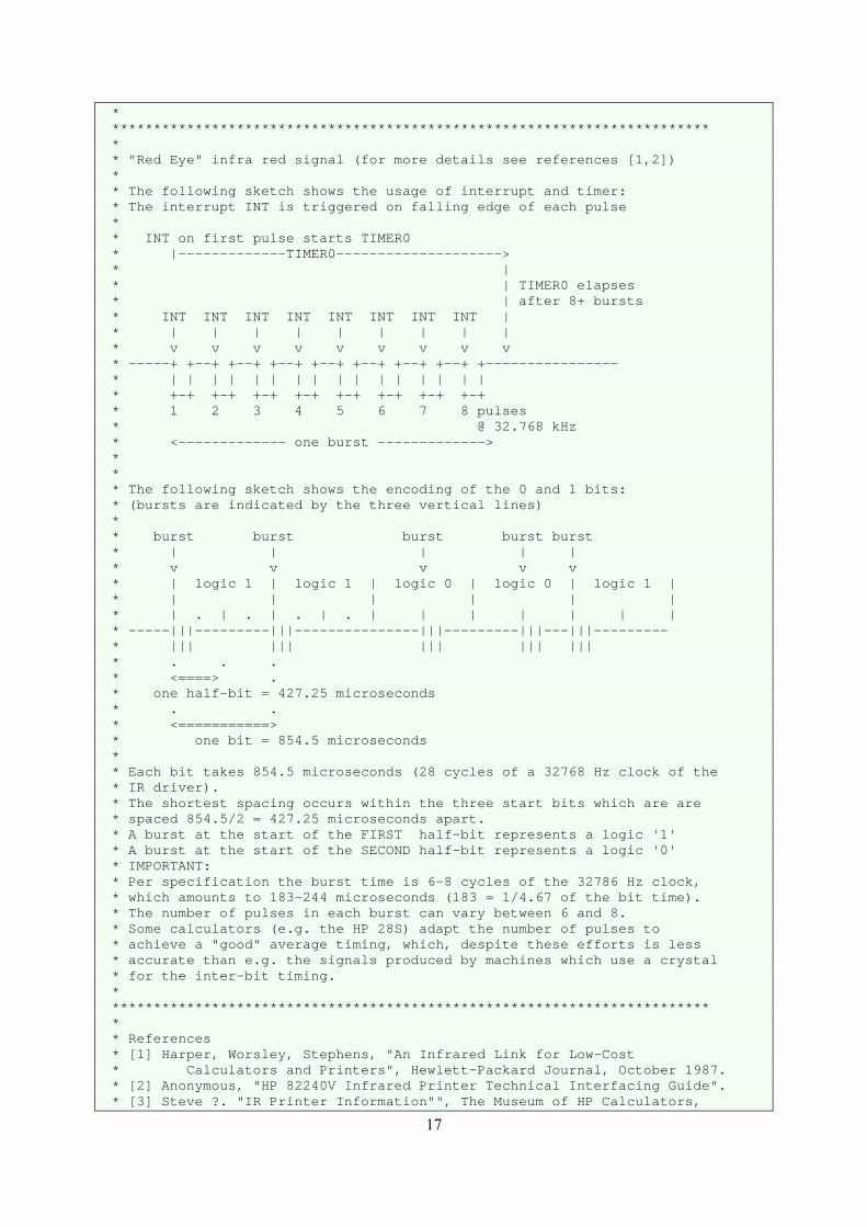
Figure 24: Inverted signal as delivered by the IR-receiver and triggering/sampling scheme controlled by
interrupt 1 and timer 0.
15
/* ************************************************************************ * A decoder for the HP82240 infrared printer protocol. ************************************************************************ * * Copyright (C) 2014-2015 Martin Hepperle. All rights reserved. * * This library is free software; you can redistribute it and/or * modify it under the terms of the GNU Lesser General Public * License as published by the Free Software Foundation; either * version 2.1 of the License, or (at your option) any later version. * ************************************************************************ * * Purpose of this code * ==================== * This software implements a decoder for the HP 82240A/B infrared * printer protocol as used by Hewlett Packard pocket calculators of * the 1980/90s (e.g. the HP 28C and S as well as the HP 48 family). * The protocol, also known as the "Red Eye" protocol was a precursor to * the IrDA standard. * Some more recent HP pocket calculators still support this protocol but * favor the IrDA standard before dropping IR links for wired RS232 and * USB connections. * The "Red Eye" protocol is also implemented in the WP34S, a repurposed * HP 20b/30b pocket calculator. * * Suitable Hardware * ================= * This software requires a receiver hardware which captures infrared * signals sent from a suitable calculator. * The decoding is done by this software using facilities of an Amtel * AVR chip, with at least one interrupt and one timer. * The output of the decoder is a serial byte stream which is sent via * a serial connection to a PC or any other device having a serial interface. * It is possible to use a serial-to-USB converter cable to simulate a COM * port via USB. * One could also easily adapt the code to support a parallel printer. * * The processing hardware can be a small Arduino (I used a Leonardo, but * a smaller variant of AVR chip would be sufficient) plus an IR receiver * connected to an input pin of the microcontroller. * * The IR receiver must be able to detect individual pulses sent with a * frequency of 32.768 kHz. * Therefore integrating receivers like the TSOP/VS family and similar are * NOT suited for this purpose. The problem with these modern (2014) * integrating receivers is that they require a pause between bursts which * is longer than the pause provided by the "Red Eye" protocol. * Therefore I used a HP C4103A receiver unit, which was originally provided * for HP laser printers. * * The range with a HP-48G is more than 1 meter and very robust. * With more recent HP calculators and the WP-34S the maximum distance is * much shorter, more something like 100 mm or even less. * * Receiving Software * ================== * The byte stream contains escape sequences which control the printer, * for example to switch to graphics mode and back. * One means to interpret this stream is Christoph Gießelinks excellent * HP 82240B printer simulator program on Windows, which can read its * input from a COM port. *

16
* For other platforms the command line printer simulator from Khanh-Dang * Nguyen Thu-Lam works well. I tried it on Windows and only a tiny * modification was required to capture incoming text and graphics. * As pure C-code this tool will also work on all other platforms which * have a C compiler (I used gcc). * * This Software * ============= * Besides the simple pass-through mode the code also implements a simple * interpreter with a state machine for control codes of the printer. * This could be modified to drive any printer or perform other tasks, * like controlling devices or whatever you like. * * All printer control sequences are decoded but in the current * implementation no special action is taken. * Bitmap graphics are also recognized and stored for further processing. * * Sending the command characters A(nalyzer), I(nterpreter), T(ranslate) via * the serial (USB) link allows to activale some special modes: * * The Interpreter mode is the normal operating mode. It passes all data * straight through. * * The Analyzer mode creates output formatted like this: * (8)27(8)26(8)54(8)27(8)53(8)80(8)53(8)54(8)53(8)54(8)53(8)27(8)80(8)53(8) * D = 'A' = 0x41, 1/2-bit = 26 * The numbers in parentheses indicate the number of pulses per burst * and the numbers between the bursts specify the gap time. * D = is the data byte recognized and at the end the half bit time * derived from the start half-bits is given. * * The Translate option switches between passing through and replacing the * character code 0x04 by a linefeed character. This allows to view the * print stream of some calculators in a terminal (emulator). * * * * Some comments on the basic architecture: * ======================================== * In order to achieve a smooth operation, one interrupt and one timer is used: * - The interrupt is used to capture the start of each pulse (when the * input pin goes low, as my IR sensor has an inverted logic). * Thus this interrupt counts all pulses within each burst. * It flags the first pulse of each burst and determines the time between * subsequent bursts. * * - Timer 0 is started to trigger just after the end of each burst * assuming the maximum nominal length of 8 pulses. * When the timer is triggered, the time to the previous bit is evaluated * and the appropriate bit value is set. There is enough time after each * burst to do this processing. * The timer also resets the pulse count to be ready for the next burst. * * - The error checking nibble and the data byte are thus composed bit by bit. * * - After the last bit has been decoded, the resulting byte is put into a * ring buffer. * * Any post-processing of the data in the ring buffer (if desired) can be * performed in the main loop. This may be interrupted at any time when * new data arrives. * This setup yields a very reliable system, even if larger amounts of data * are sent. Such larger amounts of data occur when graphics, e.g. a screen * copy, is sent.
17
* ************************************************************************ * * "Red Eye" infra red signal (for more details see references [1,2]) * * The following sketch shows the usage of interrupt and timer: * The interrupt INT is triggered on falling edge of each pulse * * INT on first pulse starts TIMER0 * |-------------TIMER0--------------------> * | * | TIMER0 elapses * | after 8+ bursts * INT INT INT INT INT INT INT INT | * | | | | | | | | | * v v v v v v v v v * -----+ +--+ +--+ +--+ +--+ +--+ +--+ +--+ +---------------- * | | | | | | | | | | | | | | | | * +-+ +-+ +-+ +-+ +-+ +-+ +-+ +-+ * 1 2 3 4 5 6 7 8 pulses * @ 32.768 kHz * <------------- one burst -------------> * * * The following sketch shows the encoding of the 0 and 1 bits: * (bursts are indicated by the three vertical lines) * * burst burst burst burst burst * | | | | | * v v v v v * | logic 1 | logic 1 | logic 0 | logic 0 | logic 1 | * | | | | | | * | . | . | . | . | | | | | | | * -----|||---------|||---------------|||---------|||---|||--------- * ||| ||| ||| ||| ||| * . . . * <====> . * one half-bit = 427.25 microseconds * . . * <===========> * one bit = 854.5 microseconds * * Each bit takes 854.5 microseconds (28 cycles of a 32768 Hz clock of the * IR driver). * The shortest spacing occurs within the three start bits which are are * spaced 854.5/2 = 427.25 microseconds apart. * A burst at the start of the FIRST half-bit represents a logic '1' * A burst at the start of the SECOND half-bit represents a logic '0' * IMPORTANT: * Per specification the burst time is 6-8 cycles of the 32786 Hz clock, * which amounts to 183-244 microseconds (183 = 1/4.67 of the bit time). * The number of pulses in each burst can vary between 6 and 8. * Some calculators (e.g. the HP 28S) adapt the number of pulses to * achieve a "good" average timing, which, despite these efforts is less * accurate than e.g. the signals produced by machines which use a crystal * for the inter-bit timing. * ************************************************************************ * * References * [1] Harper, Worsley, Stephens, "An Infrared Link for Low-Cost * Calculators and Printers", Hewlett-Packard Journal, October 1987. * [2] Anonymous, "HP 82240V Infrared Printer Technical Interfacing Guide". * [3] Steve ?. "IR Printer Information"", The Museum of HP Calculators,
18
* HP Articles Forum, 31 July 2000, [web site] * [4] "Hamming Error Correction Code", robot room, [web site]. * [5] "Error Detection Correction", supplement to Logic and Computer * Design Fundamentals, 3rd Edition, 2004. * [6] Christoph Gießelink, "redeye.c" source code from EMU28 project, 2011 . * * ************************************************************************ */ // see redeye.cpp #include "RedEye.h" /* * I have implemented an interpreter with limited postprocessing. * This can be expanded to interface to any printer or other device. * This implementation covers only the basic skeleton - a more complete * implementation is left as an exercise to the user. */ // state codes for interpreter #define TEXT 0 #define GRAPHICS 1 // character codes #define ALT_CR 4 // char 4 == carriage return/linefeed for 82440 printer #define LF 10 // char 10 #define ESC 27 // char 27 0x1B // 115200 works fine for modern PCs with USB-Serial // 9600 works fine for old PCs with Serial #define BAUD_RATE 115200 // state of the machine int state = TEXT; // for collecting a line of textual respectively graphics bytes // (must be at least 166 bytes long) #define BUFFER_SIZE 200 byte lineBuffer[BUFFER_SIZE]; // counter for textual bytes int idxLineBuffer; // special counter for graphics bytes int numGraphicsBytes = 0; // is true: translate alternate CR 0x04 to linefeed 0x10 boolean translateAltCR = false; /*****************************************************************************/ /* * This is the usual Arduino style setup() function which is executed * only once. */ void setup() // Prepare the serial output port. // You can connect Christoph Gießelinks printer simulator to the // appropriate COM port to receive and save the printout on a Windows PC. // note that this only supports baud rates up tp 9600 baud Serial.begin(BAUD_RATE); // we should make sure that Serial is ready. Possibly unnecessary, // but cannot hurt. delay(2500); // here comes the heavy stuff... setupRedEye();
19
/*****************************************************************************/ /* * This is the usual Arduino style main() loop. */ /*****************************************************************************/ void loop() // we twiddle our thumbs here - but at full speed // to conserve energy and to save the planet, one // could also reduce processor speed and speed it // up again whenever data is received. while ( true ) if ( isDataAvailable() ) // there is something in the receiving buffer // avoid that reading and updating idxRead is interrupted // pull the byte from the buffer ... byte data = getByte(); if ( ! isInterpreter() ) // not in interpreter mode // just pass the raw data Serial.write(data); else // this is our interpreter state machine switch ( state ) //---------------- case ESC: //---------------- // we are in ESCape state (previous character was ESC / 27d / 0x1B) // switch to TEXT state (may be overwritten below) state = TEXT; switch ( data ) // ESC control codes // we just swallow the following codes case 255: reset(); case 254: /* "SELF TEST" */ case 253: /* "DOUBLE WIDE" */ case 252: /* "SINGLE WIDE" */ case 251: /* "UNDERLINE" */ case 250: /* "NO UNDERLINE" */ case 249: /* "ISO 8859 Latin 1" */ case 248: /* "Roman8" */ // pass through addToBuffer(ESC); addToBuffer(data); flush(); break; /* * we can define our own escape sequences like * ESC 0 or ESC (167 to 247). * ESC 1 ... 166 is blocked by graphics. * One could also enter another mode e.g. by ESC 0, read some
20
* commands and then switch back with another ESC 0 */ case 0: // ESC 0 // swallow ESC and zero break; default: if ( data > 0 && data < 166+1 ) // within allowable range for graphics width (1...166) // empty current buffer and prepare for new graphics bytes flush(); // # of graphics bytes to follow numGraphicsBytes = data; // switch to GRAPHICS state state = GRAPHICS; else Serial.print("UNKNOWN ESC "); Serial.println(data,DEC); addToBuffer(ESC); addToBuffer(data); break; break; //---------------- case GRAPHICS: //---------------- // store the next graphics byte lineBuffer[idxLineBuffer++] = data; if ( idxLineBuffer == numGraphicsBytes ) // graphics sequence is complete // flush buffer to insert proper graphics ESCape prefix flush(); // revert to normal text mode state = TEXT; break; //---------------- default: //---------------- // not in ESCape state, not in GRAPHICS state, therefore TEXT state switch ( data ) case ESC: // 27: escape // do not output the escape character now state = ESC; break; case ALT_CR: // 0x04: alternate line feed, // is generally used by HP 48, HP 28C if ( translateAltCR ) data = LF; // replace // fall trhough
21
case LF: // 0x0A: linefeed addToBuffer(data); // ship out content of printer buffer and prepare for new data flush(); break; default: // store data in printer buffer addToBuffer(data); break; break; // check for input while ( Serial.available() > 0 ) int b = Serial.read(); switch ( b ) case 'A': // change mode setMode ( MODE_ANALYZER ); Serial.print("=>MODE_ANALYZER\n"); break; case 'I': // change mode setMode ( MODE_INTERPRETER ); Serial.print("=>MODE_INTERPRETER\n"); break; case 'T': translateAltCR = !translateAltCR; Serial.print("=>CR-translation: "); Serial.print(translateAltCR ? "ON" : "OFF"); Serial.print("\n"); break; // while ( true ) /*****************************************************************************/ void addToBuffer( byte data ) // perform possible modification here lineBuffer[idxLineBuffer++] = data; // check for line overflow (should never occur) if ( idxLineBuffer == BUFFER_SIZE ) flush(); /*****************************************************************************/ /* * Reset the printer. * */ void reset()
22
idxLineBuffer = 0; numGraphicsBytes = 0; Serial.write(0x04); /*****************************************************************************/ /* * Flush the printer buffer. * */ void flush() if ( idxLineBuffer > 0 ) if ( numGraphicsBytes > 0 && numGraphicsBytes == idxLineBuffer ) // there is some GRAPHICS in the buffer // send the graphics buffer with proper ESC+COUNT prefix Serial.write(ESC); Serial.write(numGraphicsBytes); #ifdef FUN // just for fun: invert image for ( int i=0 ; i<numGraphicsBytes ; i++ ) lineBuffer[i] = ~lineBuffer[i]; #endif Serial.write(lineBuffer,numGraphicsBytes); // reset count numGraphicsBytes = 0; else // there is some TEXT in buffer // send the graphics buffer with proper ESC+COUNT prefix Serial.write(lineBuffer,idxLineBuffer); idxLineBuffer = 0; /*****************************************************************************/ /*****************************************************************************/
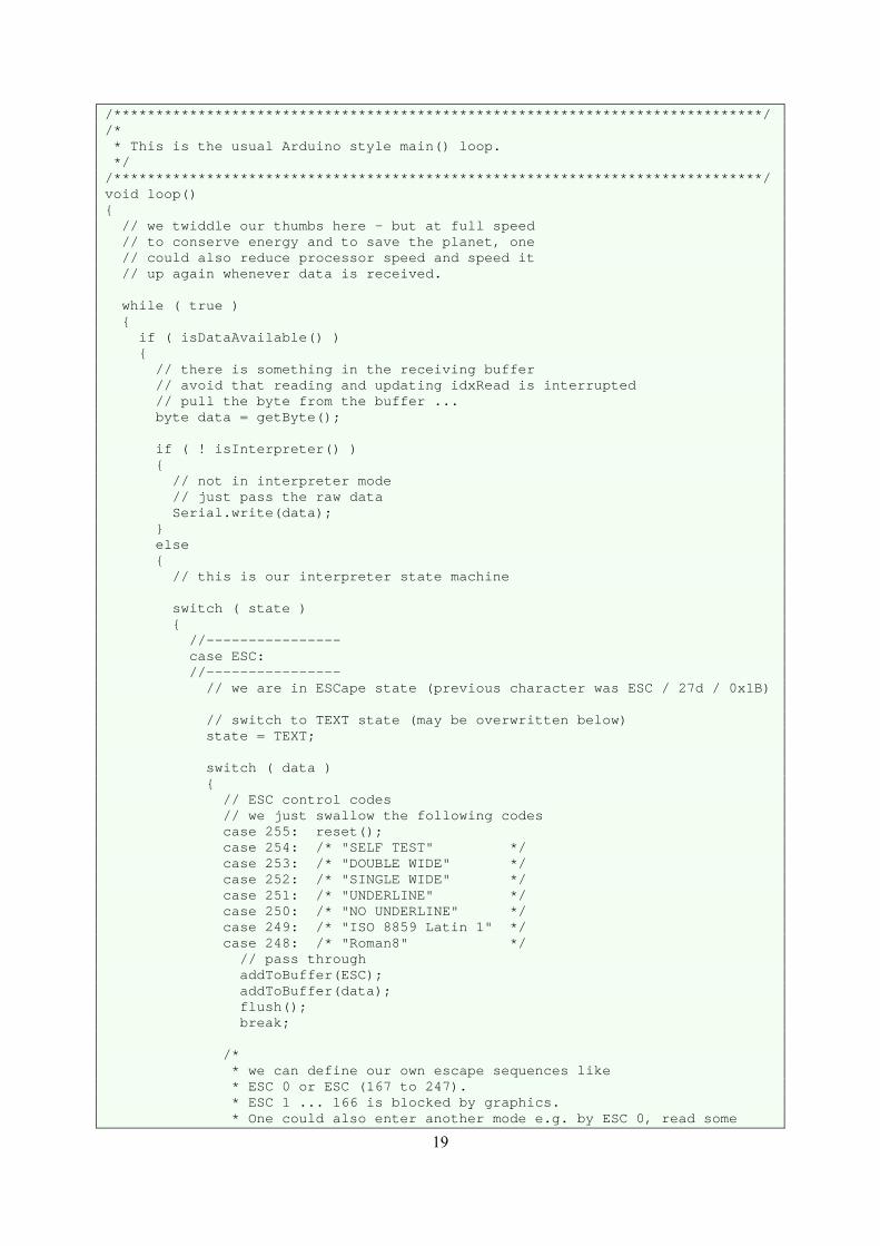
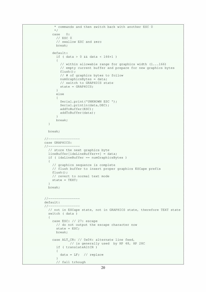
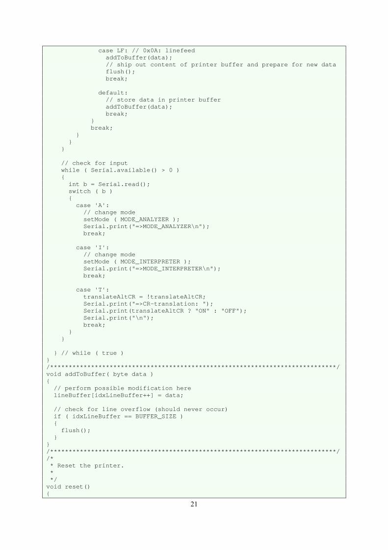
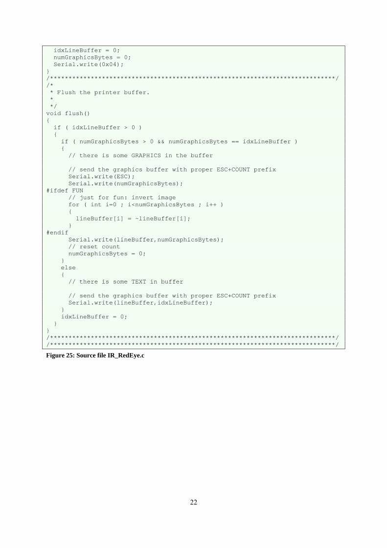
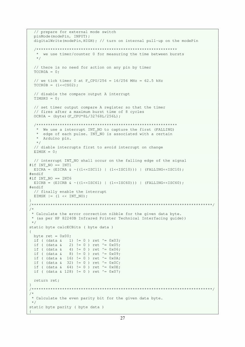
Figure 25: Source file IR_RedEye.c
23
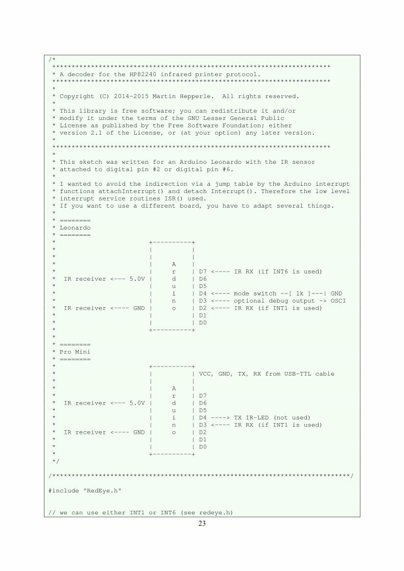
/* ************************************************************************ * A decoder for the HP82240 infrared printer protocol. ************************************************************************ * * Copyright (C) 2014-2015 Martin Hepperle. All rights reserved. * * This library is free software; you can redistribute it and/or * modify it under the terms of the GNU Lesser General Public * License as published by the Free Software Foundation; either * version 2.1 of the License, or (at your option) any later version. * ************************************************************************ * * This sketch was written for an Arduino Leonardo with the IR sensor * attached to digital pin #2 or digital pin #6. * * I wanted to avoid the indirection via a jump table by the Arduino interrupt * functions attachInterrupt() and detach Interrupt(). Therefore the low level * interrupt service routines ISR() used. * If you want to use a different board, you have to adapt several things. * * ======== * Leonardo * ======== * +----------+ * | | * | | * | A | * | r | D7 <---- IR RX (if INT6 is used) * IR receiver <--- 5.0V | d | D6 * | u | D5 * | i | D4 <---- mode switch --[ 1k ]---| GND * | n | D3 <---- optional debug output -> OSCI * IR receiver <---- GND | o | D2 <---- IR RX (if INT1 is used) * | | D1 * | | D0 * +----------+ * * ======== * Pro Mini * ======== * +----------+ * | | VCC, GND, TX, RX from USB-TTL cable * | | * | A | * | r | D7 * IR receiver <--- 5.0V | d | D6 * | u | D5 * | i | D4 ----> TX IR-LED (not used) * | n | D3 <---- IR RX (if INT1 is used) * IR receiver <---- GND | o | D2 * | | D1 * | | D0 * +----------+ */ /*****************************************************************************/ #include "RedEye.h" // we can use either INT1 or INT6 (see redeye.h)
24
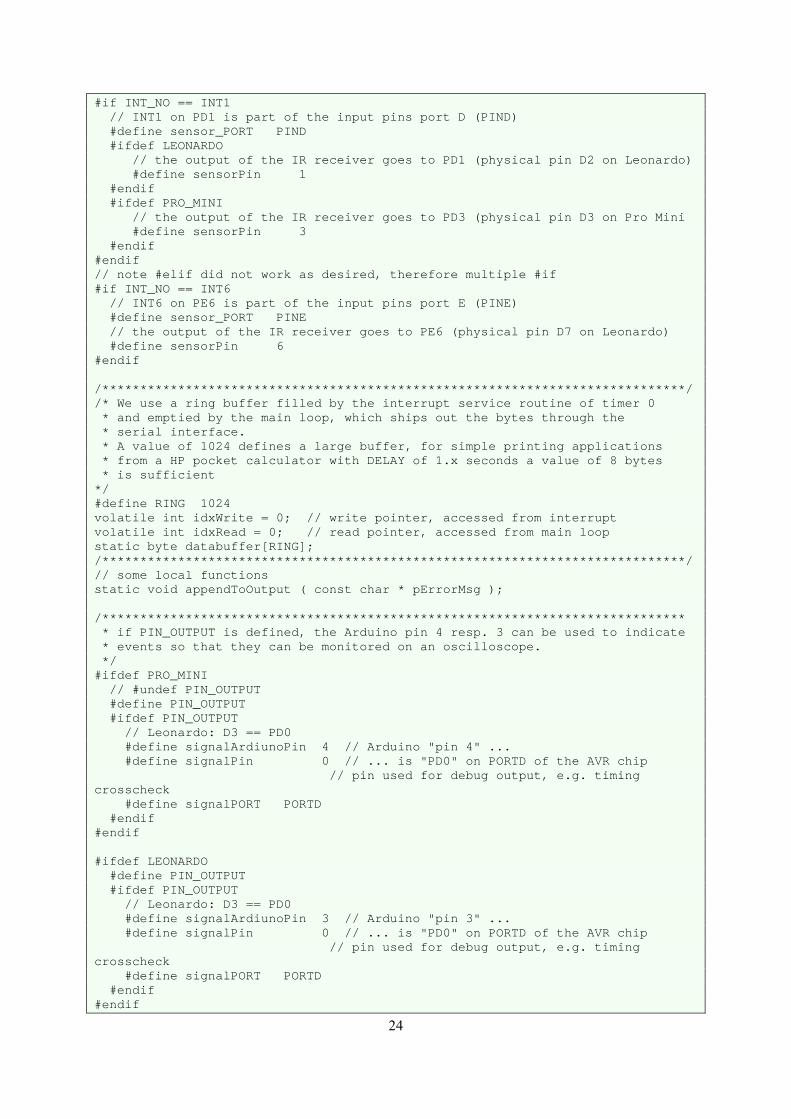
#if INT_NO == INT1 // INT1 on PD1 is part of the input pins port D (PIND) #define sensor_PORT PIND #ifdef LEONARDO // the output of the IR receiver goes to PD1 (physical pin D2 on Leonardo) #define sensorPin 1 #endif #ifdef PRO_MINI // the output of the IR receiver goes to PD3 (physical pin D3 on Pro Mini #define sensorPin 3 #endif #endif // note #elif did not work as desired, therefore multiple #if #if INT_NO == INT6 // INT6 on PE6 is part of the input pins port E (PINE) #define sensor_PORT PINE // the output of the IR receiver goes to PE6 (physical pin D7 on Leonardo) #define sensorPin 6 #endif /*****************************************************************************/ /* We use a ring buffer filled by the interrupt service routine of timer 0 * and emptied by the main loop, which ships out the bytes through the * serial interface. * A value of 1024 defines a large buffer, for simple printing applications * from a HP pocket calculator with DELAY of 1.x seconds a value of 8 bytes * is sufficient */ #define RING 1024 volatile int idxWrite = 0; // write pointer, accessed from interrupt volatile int idxRead = 0; // read pointer, accessed from main loop static byte databuffer[RING]; /*****************************************************************************/ // some local functions static void appendToOutput ( const char * pErrorMsg ); /***************************************************************************** * if PIN_OUTPUT is defined, the Arduino pin 4 resp. 3 can be used to indicate * events so that they can be monitored on an oscilloscope. */ #ifdef PRO_MINI // #undef PIN_OUTPUT #define PIN_OUTPUT #ifdef PIN_OUTPUT // Leonardo: D3 == PD0 #define signalArdiunoPin 4 // Arduino "pin 4" ... #define signalPin 0 // ... is "PD0" on PORTD of the AVR chip // pin used for debug output, e.g. timing crosscheck #define signalPORT PORTD #endif #endif #ifdef LEONARDO #define PIN_OUTPUT #ifdef PIN_OUTPUT // Leonardo: D3 == PD0 #define signalArdiunoPin 3 // Arduino "pin 3" ... #define signalPin 0 // ... is "PD0" on PORTD of the AVR chip // pin used for debug output, e.g. timing crosscheck #define signalPORT PORTD #endif #endif
25
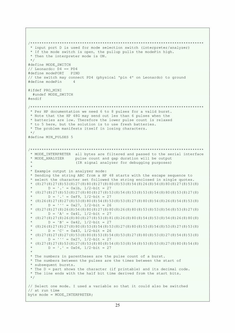
/***************************************************************************** * input port D is used for mode selection switch (interpreter/analyzer) * If the mode switch is open, the pullup pulls the modePin high. * Then the interpreter mode is ON. */ #define MODE_SWITCH // Leonardo: D4 == PD4 #define modePORT PIND // the switch may connect PD4 (physical "pin 4" on Leonardo) to ground #define modePin 4 #ifdef PRO_MINI #undef MODE_SWITCH #endif /***************************************************************************** * Per HP documentation we need 6 to 8 pulses for a valid burst. * Note that the HP 48G may send out les than 6 pulses when the * batteries are low. Therefore the lower pulse count is relaxed * to 5 here, but the solution is to use fresh batteries. * The problem manifests itself in losing characters. */ #define MIN_PULSES 5 /***************************************************************************** * MODE_INTERPRETER all bytes are filtered and passed to the serial interface * MODE_ANALYZER pulse count and gap duration will be output * (IR signal analyzer for debugging purposes) * * Example output in analyzer mode: * Sending the string ABC from a HP 48 starts with the escape sequence to * select the character set followed the string enclosed in single quotes. * (8)27(8)27(8)53(8)27(8)80(8)27(8)80(8)53(8)54(8)26(8)54(8)80(8)27(8)53(8) * D = '.' = 0x1b, 1/2-bit = 27 * (8)27(8)27(8)53(8)27(8)80(8)27(8)53(8)54(8)53(8)53(8)54(8)80(8)53(8)27(8) * D = '.' = 0xf9, 1/2-bit = 27 * (8)26(8)27(8)27(8)53(8)80(8)54(8)53(8)53(8)27(8)80(8)54(8)26(8)54(8)53(8) * D = ''' = 0x27, 1/2-bit = 26 * (8)27(8)27(8)26(8)54(8)80(8)27(8)80(8)26(8)80(8)53(8)53(8)54(8)53(8)27(8) * D = 'A' = 0x41, 1/2-bit = 27 * (8)27(8)27(8)26(8)80(8)27(8)53(8)81(8)26(8)80(8)54(8)53(8)54(8)26(8)80(8) * D = 'B' = 0x42, 1/2-bit = 27 * (8)26(8)27(8)27(8)80(8)53(8)54(8)53(8)27(8)80(8)53(8)54(8)53(8)27(8)53(8) * D = 'C' = 0x43, 1/2-bit = 26 * (8)27(8)27(8)27(8)53(8)80(8)53(8)54(8)53(8)27(8)80(8)53(8)27(8)54(8)53(8) * D = ''' = 0x27, 1/2-bit = 27 * (8)27(8)27(8)53(8)27(8)53(8)80(8)54(8)53(8)54(8)53(8)53(8)27(8)80(8)54(8) * D = '.' = 0x04, 1/2-bit = 27 * * The numbers in parentheses are the pulse count of a burst. * The numbers between the pulses are the times between the start of * subsequent bursts. * The D = part shows the character (if printable) and its decimal code. * The line ends with the half bit time derived from the start bits. */ // Select one mode. I used a variable so that it could also be switched // at run time byte mode = MODE_INTERPRETER;
26
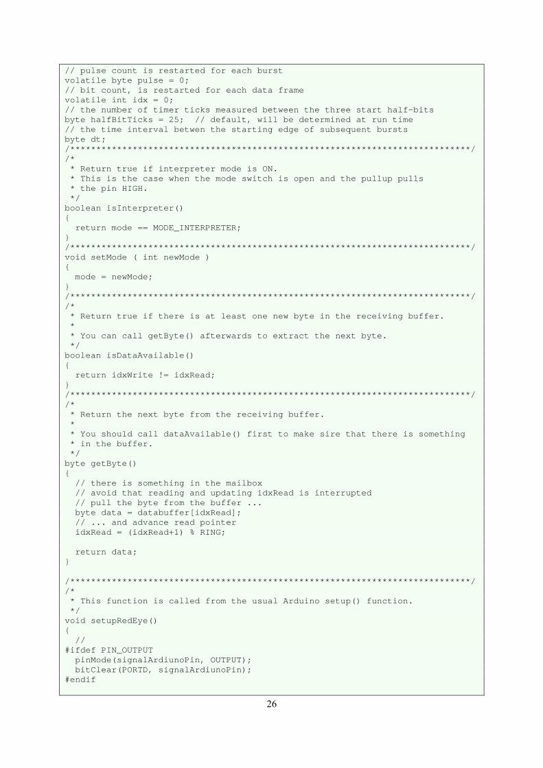
// pulse count is restarted for each burst volatile byte pulse = 0; // bit count, is restarted for each data frame volatile int idx = 0; // the number of timer ticks measured between the three start half-bits byte halfBitTicks = 25; // default, will be determined at run time // the time interval betwen the starting edge of subsequent bursts byte dt; /*****************************************************************************/ /* * Return true if interpreter mode is ON. * This is the case when the mode switch is open and the pullup pulls * the pin HIGH. */ boolean isInterpreter() return mode == MODE_INTERPRETER; /*****************************************************************************/ void setMode ( int newMode ) mode = newMode; /*****************************************************************************/ /* * Return true if there is at least one new byte in the receiving buffer. * * You can call getByte() afterwards to extract the next byte. */ boolean isDataAvailable() return idxWrite != idxRead; /*****************************************************************************/ /* * Return the next byte from the receiving buffer. * * You should call dataAvailable() first to make sire that there is something * in the buffer. */ byte getByte() // there is something in the mailbox // avoid that reading and updating idxRead is interrupted // pull the byte from the buffer ... byte data = databuffer[idxRead]; // ... and advance read pointer idxRead = (idxRead+1) % RING; return data; /*****************************************************************************/ /* * This function is called from the usual Arduino setup() function. */ void setupRedEye() // #ifdef PIN_OUTPUT pinMode(signalArdiunoPin, OUTPUT); bitClear(PORTD, signalArdiunoPin); #endif
27
// prepare for external mode switch pinMode(modePin, INPUT); digitalWrite(modePin,HIGH); // turn on internal pull-up on the modePin /************************************************************ * we use timer/counter 0 for measuring the time between bursts */ // there is no need for action on any pin by timer TCCR0A = 0; // we tick timer 0 at F_CPU/256 = 16/256 MHz = 62.5 kHz TCCR0B = (1<<CS02); // disable the compare output A interrupt TIMSK0 = 0; // set timer output compare A register so that the timer // fires after a maximum burst time of 8 cycles OCR0A = (byte)(F_CPU*8L/32768L/256L); /************************************************************ * We use a interrupt INT_NO to capture the first (FALLING) * edge of each pulse. INT_NO is associated with a certain * Arduino pin. */ // diable interrupts first to avoid interrupt on change EIMSK = 0; // interrupt INT_NO shall occur on the falling edge of the signal #if INT_NO == INT1 EICRA = (EICRA & ~((1<<ISC11) | (1<<ISC10))) | (FALLING<<ISC10); #endif #if INT_NO == INT6 EICRB = (EICRB & ~((1<<ISC61) | (1<<ISC60))) | (FALLING<<ISC60); #endif // finally enable the interrupt EIMSK |= (1 << INT_NO); /*****************************************************************************/ /* * Calculate the error correction nibble for the given data byte. * (as per HP 82240B Infrared Printer Technical Interfacing guide)) */ static byte calcECBits ( byte data ) byte ret = 0x00; if ( (data & 1) != 0 ) ret ^= 0x03; if ( (data & 2) != 0 ) ret ^= 0x05; if ( (data & 4) != 0 ) ret ^= 0x06; if ( (data & 8) != 0 ) ret ^= 0x09; if ( (data & 16) != 0 ) ret ^= 0x0A; if ( (data & 32) != 0 ) ret ^= 0x0C; if ( (data & 64) != 0 ) ret ^= 0x0E; if ( (data & 128) != 0 ) ret ^= 0x07; return ret; /*****************************************************************************/ /* * Calculate the even parity bit for the given data byte. */ static byte parity ( byte data )
28
byte ret = 0x00; if ( (data & 1) != 0 ) ret++; if ( (data & 2) != 0 ) ret++; if ( (data & 4) != 0 ) ret++; if ( (data & 8) != 0 ) ret++; if ( (data & 16) != 0 ) ret++; if ( (data & 32) != 0 ) ret++; if ( (data & 64) != 0 ) ret++; if ( (data & 128) != 0 ) ret++; return ret % 2; /*****************************************************************************/ /* * Append a null terminated string to the output buffer. */ static void appendToOutput ( const char * pErrorMsg ) while ( *pErrorMsg ) databuffer[idxWrite] = *pErrorMsg; idxWrite = (idxWrite+1) % RING; pErrorMsg++; /*****************************************************************************/ /* * Output the number of pulses during this burst. * used when ANALYZER mode is active. */ static void outputPulseCount() char s[8]; appendToOutput ("("); itoa(pulse, s, 10 ); appendToOutput ( s ); appendToOutput (")"); /*****************************************************************************/ /* * Output the time between this and the previous burst. * used when ANALYZER mode is active. */ static void outputGapTime() char s[8]; itoa(dt, s, 10 ); appendToOutput ( s ); /*****************************************************************************/ /* * This handler routine is called when the comparison A interrupt of * timer/counter 0 occurs. * Counter 0 is reset at the first edge of a burst and the comparison * register is set to a value which covers 8 cycles of the 32768 Hz * burst signal. Thus this interrupt is called when a burst is just * over and the time elapsed since the previous burst has been stored * in the variable dt by the edge detection interrupt. * The processing time for the idx == 14 case is the longest and takes * about 45 us. This still fits nicely in the gap before the next data * frame can be expected. */ ISR(TIMER0_COMPA_vect)
29
#ifdef PIN_OUTPUT // signal start of activity bitSet(signalPORT, signalPin); #endif if ( pulse < MIN_PULSES ) // If the timer elapsed and we got less than MIN_PULSES pulses, // no burst is in progress. // This acts then as a watchdog event to make sure we are ready // for the next data byte, even if something went wrong pulse = 0; idx = 0; #ifdef MODE_SWITCH // check mode switch if ( (modePORT & _BV(modePin)) == _BV(modePin) ) setMode ( MODE_INTERPRETER ); else setMode ( MODE_ANALYZER ); #endif else // we arrive here after a burst of up to 8 pulses has finished /* The index counter idx works as follows: * * S S S E E E E 7 6 5 4 3 2 1 0 * |__|__|__|__|__|__|__|__|__|__|__|__|__|__| * idx 0 1 2 3 4 5 6 7 8 9 10 12 13 14 15 * */ if ( idx == 0 ) // this is the start of first burst if ( mode == MODE_ANALYZER ) // output the number of pulses during this burst outputPulseCount(); else // this is the start of the second or later burst //------------------- if ( mode == MODE_ANALYZER ) // output the time interval between bursts outputGapTime(); // output the number of pulses during this burst outputPulseCount(); //------------------- if ( idx == 1 )
30
// second start half-bit // gap 1 after second burst halfBitTicks = dt; else if ( idx == 2 ) // third start half-bit // gap 2 after third burst // take the average of the two gaps between the three start half-bits halfBitTicks = (halfBitTicks + dt) >> 1; else // other gaps // use static variables as we return here 12 times to compose the // 4 ECC bits and the 8 data bits step by step static byte lastbit = 0; static byte token = 0; static byte missed = 0; static byte ECC = 0; static byte data = 0; // ECC: idx=3,4,5,6 // data: idx=7,8,9,10,11,12,13,14 if ( idx == 3 ) // start of the error correction nibble // set lastbit from last start half-bit which equals a zero lastbit = 0; // reset bit collector token = 0; // start with no missed bits in ECC nibble missed = 0; else if ( idx == 7 ) // start of the data byte // we carry lastbit over from ECC // reset bit collector token = 0; // start with no missed bits in data byte missed = 0; // determine number of 1/2-bit intervals since last burst (rounded up) int t = (dt + halfBitTicks/4) / halfBitTicks; if ( lastbit == 1 ) // we have to adjust by one interval to match the correct // interval in the following switch (t) t--; // here we detect the bit sequence for this interval // in case of missed bits we remember this in the // missed bit mask and also increment the index idx. // this could be written more compact, but I preferred a readable form switch ( t ) case 0: // second burst in same bit: this is an error which we ignore
31
break; case 1: // one bit '1' lastbit = 1; token <<= 1; // slot for new bit token |= lastbit; // set '1' missed <<= 1; // no missed bit, just move mast to the left break; case 2: // one bit '0' lastbit = 0; token <<= 1; // slot for new bit // nothing to set for '0' missed <<= 1; // no missed bit, just move mast to the left break; case 3: // one missed bit, one bit '1' lastbit = 1; token <<= 1; // skip missed bit token <<= 1; // slot for new bit token |= lastbit; // set '1' missed <<= 1; // move mask to the left missed |= 1; // insert one missed bit idx++; // account for missed bit in bit count break; case 4: // one missed bit, one bit '0' lastbit = 0; token <<= 1; // skip missed bit token <<= 1; // slot for new (null) bit // nothing to set for '0' missed <<= 1; missed |= 1; // insert one missed bit idx++; // account for missed bit in bit count break; case 5: // two missed bits, one bit '1' lastbit = 1; token <<= 1; // missed bit token <<= 1; // missed bit token <<= 1; // slot for new bit token |= lastbit; // set '1' missed <<= 1; missed |= 1; idx++; // account for missed bit in bit count missed <<= 1; missed |= 1; idx++; // account for missed bit in bit count break; case 6: // two missed bits, one bit '0' lastbit = 0; token <<= 1; // missed bit token <<= 1; // missed bit token <<= 1; // slot for new (null) bit // nothing to set for '0' missed <<= 1; missed |= 1; idx++; // account for missed bit in bit count missed <<= 1; missed |= 1; idx++; // account for missed bit in bit count break;
32
// anything else would be an error which we ignore if ( idx == 6 ) // we have captured all 4 error correction bits // note: ECC: idx=3,4,5,6 if ( missed ) // missed bit(s) in ECC nibble // it does not make sense to try a correction of the data byte ECC = 0; else // save for possible later correction of the data byte ECC = token; else if ( idx == 14 ) // we have captured all 8 data bits // note: data: idx=7,8,9,10,11,12,13,14 if ( missed > 0 ) // there are more than three missed bit(s) in data byte // error message shows missed bits as a binary mask char s[8]; appendToOutput ( "M=" ); itoa( missed, s, 2 ); appendToOutput ( s ); appendToOutput ( "" ); //byte checkECC = calcECBits ( token ); // correction of missed bits if ( ECC != 0 && missed > 0 && missed < 3 ) // ECC nibble is o.k. and we have one or two missed bits //static const byte H[] = 0x78, 0xE6, 0xD5, 0x8B ; static const byte H[] = 0b01111000, 0b11100110, 0b11010101, 0b10001011 ; while ( missed != 0x00 ) for ( byte i=0 ; i<4 ; i++ ) // handle the four ECC bits from left to right byte mask = H[i]; byte x = missed & mask; if ( parity( x ) == 1 ) // this mask has exactly one bit in common with the // missed bit mask if ( parity ( token & mask ) != ((ECC>>(3-i)) & 0x01) ) // set bit
33
token |= x; // else // bit stays empty // nullify missed bit missed &= ~x; // continue with next missed bit (if any) break; // correction of missed bits //------------------- if ( mode == MODE_ANALYZER ) // output the half bit time for information char s[8]; appendToOutput ( " = '" ); s[0] = token > 31 ? (token < 128 ? token : '.') : '.'; s[1] = '\0'; appendToOutput ( s ); appendToOutput ( "' = 0x" ); if ( token < 16 ) appendToOutput ( "0" ); itoa(token, s, 16 ); appendToOutput ( s ); appendToOutput ( ", 1/2-bit = " ); itoa(halfBitTicks, s, 10 ); appendToOutput ( s ); appendToOutput ( "\n" ); //------------------- if ( mode == MODE_INTERPRETER ) databuffer[idxWrite] = token; idxWrite = (idxWrite+1) % RING; // the last burst is over // reset index for storing timing of next byte // will be incremented to 0 below idx = -1; // idx == 14 // idx > 2 // idx > 0 // burst is over, prepare for next bit idx++; // prepare for next burst pulse = 0; #ifdef PIN_OUTPUT // set output pin to low to signal end of activity bitClear(signalPORT, signalPin); #endif /*****************************************************************************/ /* * This interrupt function is called when the input pin with the IR sensor
34
* drops (negative logic). * This indicates the start of a cycle of an IR-burst. */ #if INT_NO==INT1 ISR(INT1_vect) #endif #if INT_NO==INT6 ISR(INT6_vect) #endif // check for the first pulse and increment the pulse count if ( pulse++ == 0 ) // this is the first pulse of a burst // save time since start of last burst dt = TCNT0; // restart the timer to measure the time to the next burst TCNT0 = 0; // enable output compare A interrupt TIMSK0 = (1<<OCIE0A); // Now a burst is in progress. The index idx will be increased after // the burst is over in the TIMER0_COMPA_vect service routine. /*****************************************************************************/
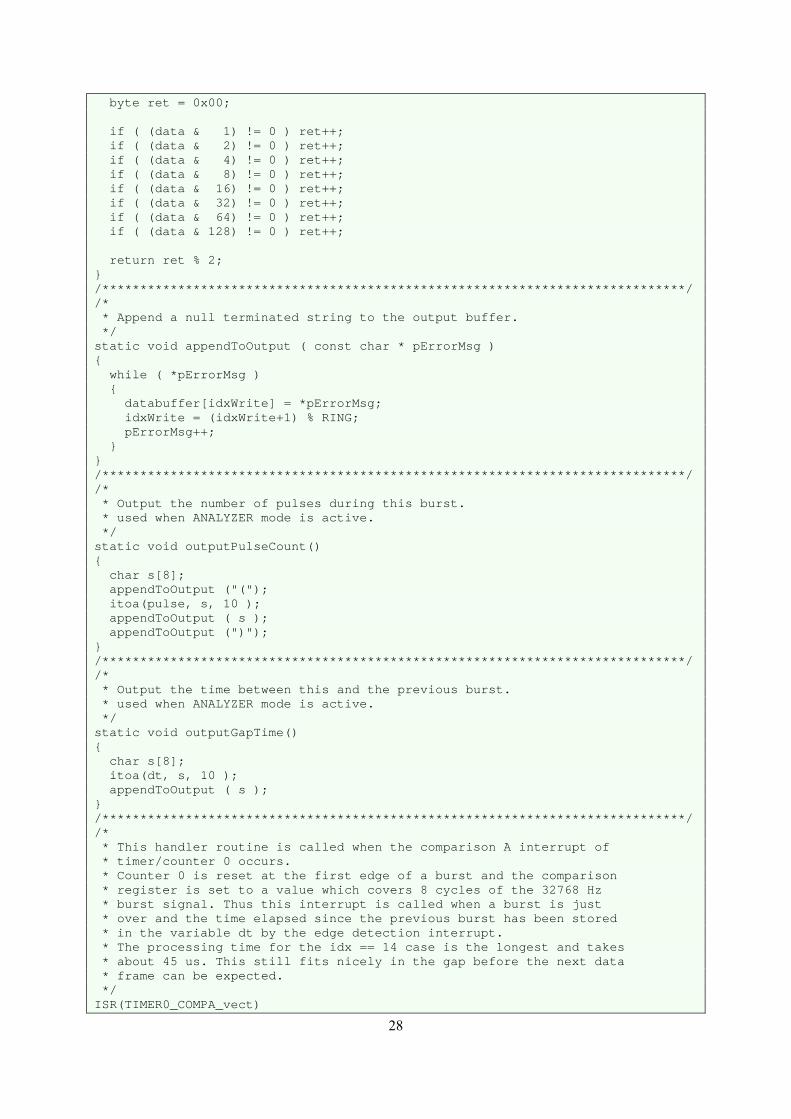
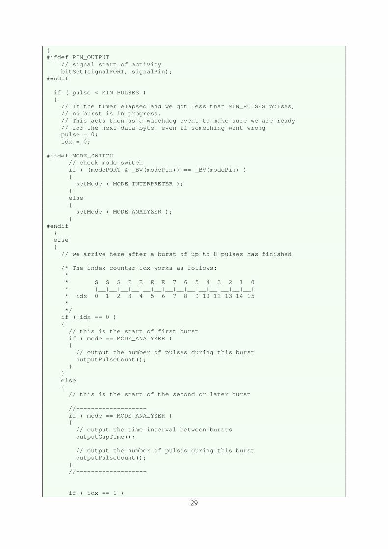
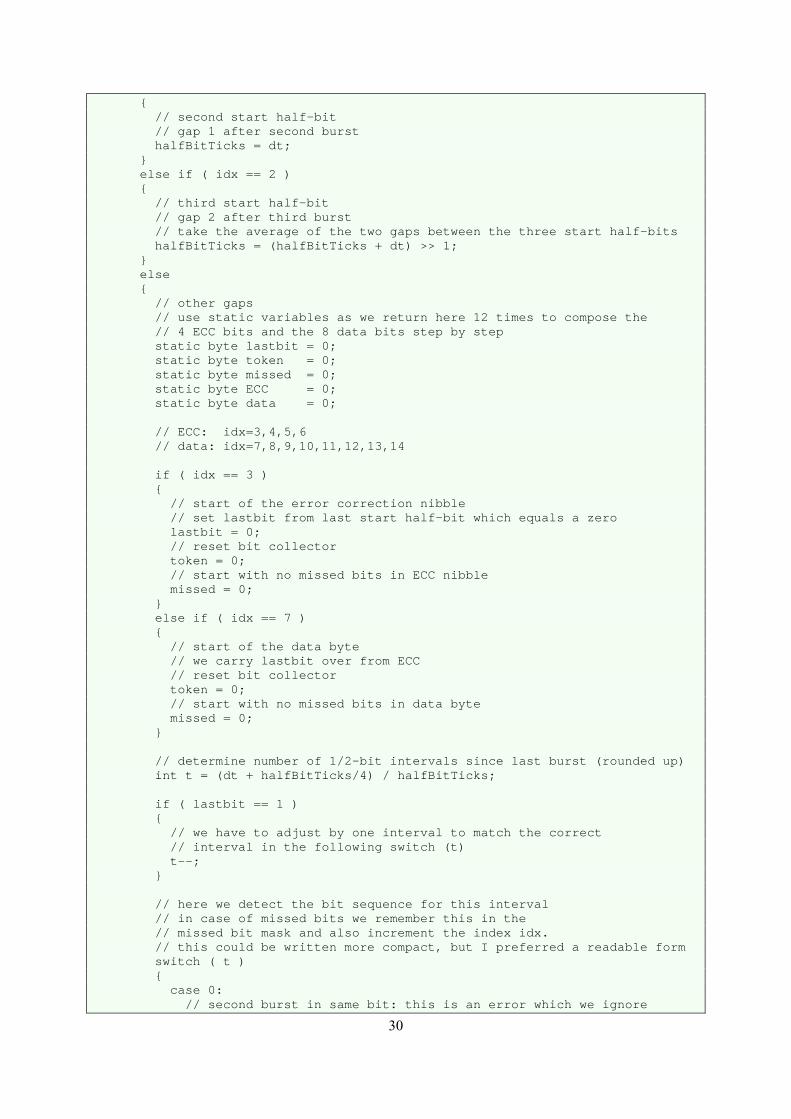
Figure 26: Source file RedEye.cpp
35
/* ************************************************************************ * A decoder for the HP82240 infrared printer protocol. ************************************************************************ * * Copyright (C) 2014-2015 Martin Hepperle. All rights reserved. * * This library is free software; you can redistribute it and/or * modify it under the terms of the GNU Lesser General Public * License as published by the Free Software Foundation; either * version 2.1 of the License, or (at your option) any later version. * ************************************************************************ */ #include <Arduino.h> /* Adapt pin and port as needed * * Here we use interrupt 1 or interrupt 6 * * Example: interrupt 1: * In the ATmega32U4 chip this is connected to pin PD1 (pin 1 of port D). * On the Arduino Leonardo board this is connected to digital Pin D2. * So we connect the wire to Pin 2, but in the code we have to use * the ATmega parameters for "input pins, port D" (PIND) and pin 1 (PD1). * * If we want to use SDA and SCL on pins D2, D3 so that we cannot use INT1. * Then we can use INT6 on pin D7 */ #define INT_NO INT1 //#define INT_NO INT6 /* * If we use a Pro Mini the pin mapping has to be adapted */ // #define LEONARDO #define PRO_MINI /****************************************************/ #define MODE_INTERPRETER 1 #define MODE_ANALYZER 2 /****************************************************/ // global functions extern void setupRedEye(); extern boolean isDataAvailable(); extern byte getByte(); extern boolean isInterpreter(); extern void setMode ( int ); /****************************************************/
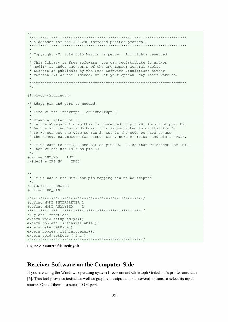
Figure 27: Source file RedEye.h
Receiver Software on the Computer Side If you are using the Windows operating system I recommend Christoph Gießelink’s printer emulator
[6]. This tool provides textual as well as graphical output and has several options to select its input
source. One of them is a serial COM port.
36
If you are using other systems you may find some older receiver software on the various HP
enthusiasts web sites. The command line printer simulator from Khanh-Dang Nguyen Thu-Lam works
well. I tried it on Windows and only a tiny modification was required to capture incoming text and
graphics. As pure C-code this tool will also work on all other platforms which have a C compiler (I
used gcc).
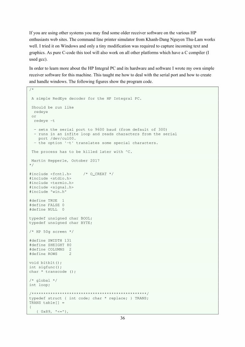
In order to learn more about the HP Integral PC and its hardware and software I wrote my own simple
receiver software for this machine. This taught me how to deal with the serial port and how to create
and handle windows. The following figures show the program code.
/* A simple RedEye decoder for the HP Integral PC. Should be run like redeye or redeye -t - sets the serial port to 9600 baud (from default of 300) - runs in an infite loop and reads characters from the serial port /dev/cul00. - the option '-t' translates some special characters. The process has to be killed later with ^C. Martin Hepperle, October 2017 */ #include <fcntl.h> /* O_CREAT */ #include <stdio.h> #include <termio.h> #include <signal.h> #include "win.h" #define TRUE 1 #define FALSE 0 #define NULL 0 typedef unsigned char BOOL; typedef unsigned char BYTE; /* HP 50g screen */ #define SWIDTH 131 #define SHEIGHT 80 #define COLUMNS 2 #define ROWS 2 void bitblt(); int sigfunc(); char * transcode (); /* global */ int loop; /*************************************************/ typedef struct int code; char * replace; TRANS; TRANS table[] = 0x89, "<=",
37
0x8A, ">=" , 0x8B, "!=" , 0x8D, "->" , 0x8E, "<-" , 0x8F, "/^" , 0x90, "\v" , 0xBB, ">>" , 0xAB, "<<" ; /* Searches table[] for a match of character code c * Returns NULL if no match was found. */ char * transcode ( c ) int c; int i; char * ret; ret = NULL; for ( i=0 ; i<sizeof(table)/sizeof(TRANS) ; i++ ) if ( c == table[i].code ) ret = table[i].replace; break; return ret; /*************************************************/ main ( argc, argv ) int argc; char * argv[]; char * pPort = "/dev/cul00"; struct termio tio; int request; char buffer; int i; int grafBytes; char grafBuffer[166]; char * pBuffer; char * p; BOOL inESC; int x, y, width, height; unsigned char b; BOOL translate = FALSE; int fd_serial; int fd_graph, fd_print; int fd_falpha; int new_font; FILE * fp_print; FILE * fp_log; signal ( SIGINT, sigfunc ); signal ( SIGQUIT, sigfunc ); fprintf ( stdout, "characters 128...255:\r\n" ); for ( i=128 ; i<256 ; i++ ) if ( i % 16 == 0 )
38
putc ( 13, stdout ); putc ( 10, stdout ); b = (unsigned char)(i & 0xFF); putc ( (unsigned char)i, stdout ); putc ( 13, stdout ); putc ( 10, stdout ); fprintf ( stdout, "RedEye started.\r\nInitializing...\r\n" ); fflush ( stdout ); while ( --argc > 0 ) if ( argv[argc][0] == '-' && argv[argc][1] == 't' ) translate = TRUE; fprintf ( stdout, "Translation active.\r\n" ); fd_serial = open ( pPort, O_RDONLY | O_NDELAY, O_CREAT ); if ( fd_serial > 0 ) fprintf ( stdout, "Port %s opened...\r\n", pPort ); fflush ( stdout ); /* graphics window */ width = COLUMNS*SWIDTH +(COLUMNS-1)*3; height = ROWS*SHEIGHT; fd_graph = open_graph ( width, height, 512 - width - 8, 8 ); fd_print = open_print ( 32*6, 24*8, 8, 8 ); fp_print = fdopen ( fd_print, "w" ); /* this part is not needed, only if you want to use a special font */ if ( (fd_falpha = fainit ( fd_print, "TERM0" )) < 0 ) fprintf ( stderr, "Cannot init fast alpha.\n" ); if ( (new_font = fafontload ( fd_falpha, "ecma94.font" )) == -1 ) fprintf ( stderr, "Cannot load font.\n" ); fafontactivate ( fd_falpha, new_font ); /* this part ... */ fp_log = fopen ( "redeye.log", "w" ); /* move cursor to upper left */ x = 0; y = height-1; /* set serial port charactersitics */ request = TCSETA; tio.c_iflag = 0; tio.c_oflag = 0; tio.c_lflag = 0; tio.c_cflag = CREAD | B9600 | CS8; /* control chars */ tio.c_cc[0] = 0x7F; /* INTR = DEL */ tio.c_cc[1] = 0x1C; /* QUIT = FS */ tio.c_cc[2] = 0x23; /* ERASE = # */ tio.c_cc[3] = 0x40; /* KILL = @ */
39
tio.c_cc[4] = 0x04; /* EOF = EOT */ tio.c_cc[5] = 0x00; /* EOL + NUL */ tio.c_cc[6] = 0x00; /* reserved 1 */ tio.c_cc[7] = 0x00; /* reserved 2 */ ioctl ( fd_serial, request, &tio ); fprintf ( fp_print, "...9600 baud,\n" ); fprintf ( fp_print, "...no parity,\n" ); fprintf ( fp_print, "...1 stop bit.\n" ); inESC = FALSE; grafBytes = 0; loop = TRUE; fprintf ( fp_print, "Ready...\n" ); while ( loop ) i = read ( fd_serial, &buffer, 1 ); if ( i == 1 ) i = buffer & 0xFF; if ( inESC ) switch ( i ) case 255: /* reset */ fprintf ( stdout, "==> Reset\r\n" ); break; case 254: /* self-test */ fprintf ( stdout, "==> Self-Test\r\n" ); break; case 253: /* start double wide */ fprintf ( stdout, "==> Double-Wide ON\r\n" ); break; case 252: /* start single wide */ fprintf ( stdout, "==> Single-Wide ON\r\n" ); break; case 251: /* start underline */ fprintf ( stdout, "==> Underline ON\r\n" ); break; case 250: /* stop underline */ fprintf ( stdout, "==> Underline OFF\r\n" ); break; case 249: /* start ISO 8859 Latin 1 */ fprintf ( stdout, "==> ISO Latin 1\r\n" ); break; case 248: /* start Roman8 */ fprintf ( stdout, "==> Roman 8\r\n" ); break; default: /* graphics */ grafBytes = i; pBuffer = grafBuffer; break; inESC = FALSE; else if ( grafBytes > 0 ) grafBytes--; *pBuffer++ = i;
40
if ( grafBytes == 0 ) i = pBuffer - grafBuffer; /* buffer full: output it ... */ bitblt ( fd_graph, x, y, grafBuffer, i ); y -= 8; if ( y < 7 ) x += SWIDTH + 3; y = height-1; if ( x > width ) x = 0; else moveto ( fd_graph, x-2, height-1 ); lineto ( fd_graph, x-2, 1 ); grafBytes = -1; else switch ( i ) case 0x0A: /* regular LF */ case 0x04: /* alternate LF */ if ( grafBytes < 0 ) /* swallow newline after bitmap */ grafBytes = 0; else fprintf ( fp_print, "\n" ); fprintf ( fp_log, "\r\n" ); break; case 0x09: /* TAB */ fprintf ( fp_print, " " ); fprintf ( fp_log, " " ); break; case 0x1B: inESC = TRUE; break; default: if ( translate ) p = transcode ( i ); else p = NULL; if ( p ) fprintf ( fp_print, "%s", p ); fprintf ( fp_log, "%s", p ); else putc ( i, fp_print ); putc ( i, fp_log ); break;
41
fflush ( stdout ); fflush ( fp_print ); faterminate ( fd_falpha ); close ( fd_serial ); fclose ( fp_print ); fclose ( fp_log ); close_window ( fd_graph ); close_window ( fd_print ); fprintf ( stdout, "Program terminated, port closed.\r\n" ); /*************************************************/ int sigfunc ( signo ) int signo; loop = FALSE; return 0; /*************************************************/ dump( fp, tio ) FILE * fp; struct termio * tio; int i; fprintf ( fp, "iflag = 0x%04X\r\n", tio->c_iflag ); fprintf ( fp, "oflag = 0x%04X\r\n", tio->c_oflag ); fprintf ( fp, "cflag = 0x%04X\r\n", tio->c_cflag ); fprintf ( fp, "lflag = 0x%04X\r\n", tio->c_lflag ); fprintf ( fp, "line = 0x%02X\r\n", tio->c_line ); fprintf ( fp, "cc[] = 0x%02X", tio->c_cc[0] ); for ( i=1 ; i<NCC ; i++ ) fprintf ( fp, ", 0x%02X", tio->c_cc[i] ); fprintf ( fp, "\r\n" ); /*************************************************/ /* * Displays bitmap n its natural orientation, * as a vertical band, 8 pixels wide. */ void olde_bitblt ( fd, x, y, buffer, columns ) int fd; int x, y; char * buffer; int columns; char * pBuffer; char * p; int i;
42
/* width must be multiple of 16 bits */ pBuffer = (char *)malloc( 2*columns ); p = pBuffer; for ( i=0 ; i<columns ; i++ ) *p = ~(*buffer); p += 2; /* pad to even address */ buffer++; write_raster ( fd, x, y, 8, columns, pBuffer, (char)3 ); free ( pBuffer ); /*************************************************/ /* * rotates the bitmap so that a horizontal band 8 pixels high results */ void bitblt ( fd, x, y, buffer, columns ) int fd; int x, y; char * buffer; int columns; char * pBuffer; char * p; int w, c, r; BYTE shift; BYTE mask; /* width must be multiple of 16 bits */ w = 2 * ((columns + 15) / 16); pBuffer = (char *)malloc( 8 * w ); p = pBuffer; for ( mask = 0x01 ; mask != 0x00 ; mask <<= 1 ) shift = 7; for ( c=0 ; c<columns ; c++ ) if ( shift == 7 ) /* set first bit */ *p = (*buffer & mask) == 0 ? 1 << shift : 0; else /* or in following bits */ *p |= (*buffer & mask) == 0 ? 1 << shift : 0; if ( shift == 0 ) /* advance to next byte */ p++; shift = 7; else shift -= 1; buffer++; /* advance to next scanline */ pBuffer += w; p = pBuffer;
43
buffer -= columns; pBuffer -= 8*w; write_raster ( fd, x, y, columns, 8, pBuffer, (char)3 ); free ( pBuffer ); /*************************************************/
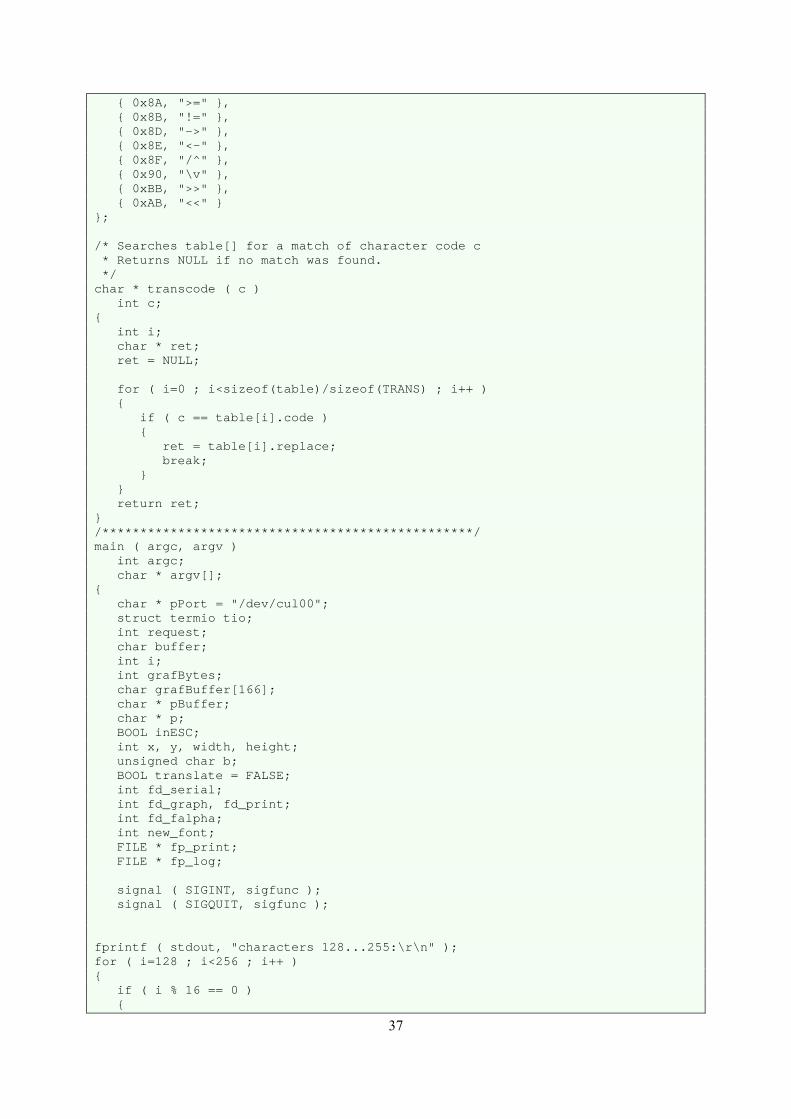
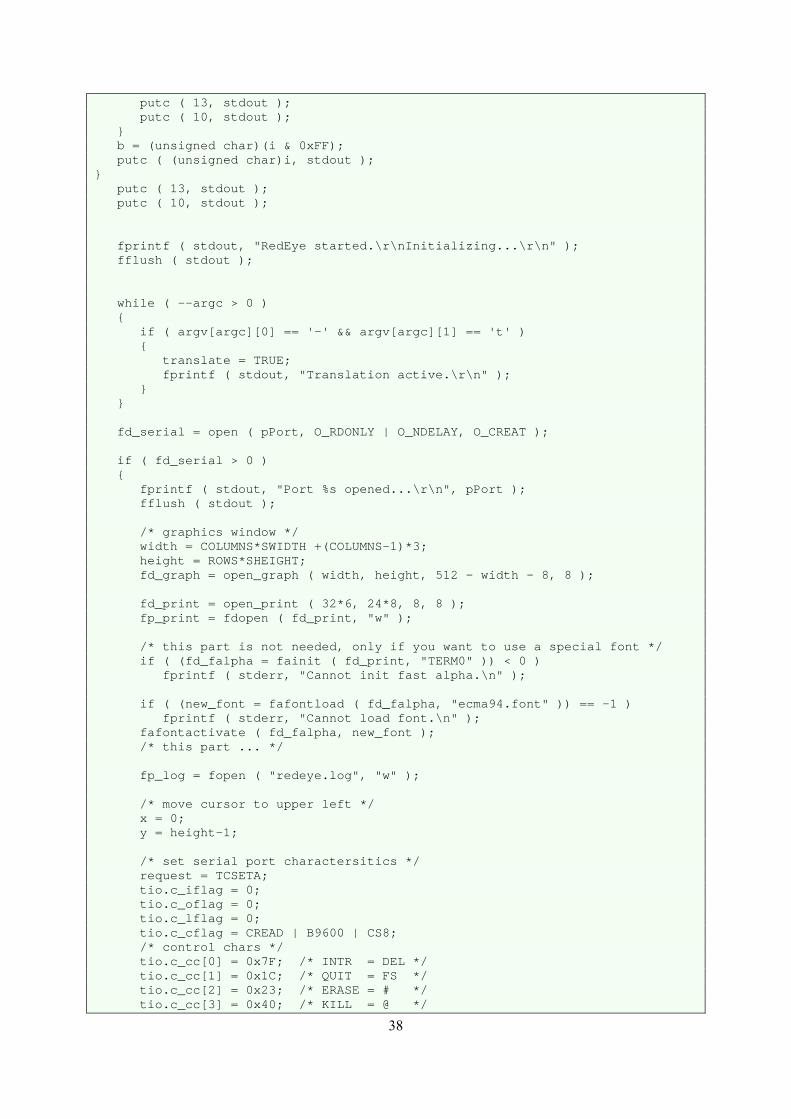
Figure 28: Source file RedEye.c for the HP Integral PC.
int open_graph(); int write_raster(); void moveto(); void lineto(); int close_graph(); void setraw(); void restoretty(); int open_print(); int close_print(); extern int errno;
Figure 29: Source file win.h for the HP Integral PC.
#include <stdio.h> #include <string.h> #include <termio.h> #include <scrn/disp.h> #include <scrn/wmcom.h> #include <scrn/plotem.h> #include <fcntl.h> #include <scrn/keycode.h> int open_graph ( xsize, ysize, xloc, yloc ) int xsize, ysize; int xloc, yloc; int fd; struct windio plot; char * p; ioctl ( 0, WMGET, &plot ); plot.w_type = PETYPE; plot. w_stat |= AUTO_SH | AUTO_DEST; plot.w_width = xsize; plot.w_height = ysize; plot.w_xloc = xloc; plot.w_yloc = yloc; plot.w_gen1 = 0; plot.w_gen2 = 0; p = plot.w_path; strcpy ( strrchr ( plot.w_path, '/' ), "/RedEye" ); ioctl ( 0, WMCREATE, &plot ); fd = open ( plot.w_path, O_RDWR ); return fd;
44
int close_window ( fd ) int fd; close ( fd ); return 0; int open_print ( xsize, ysize, xloc, yloc ) int xsize, ysize; int xloc, yloc; int fd; struct windio plot; char * p; ioctl ( 0, WMGET, &plot ); plot.w_type = T0TYPE; plot. w_stat |= AUTO_SH | AUTO_DEST; plot.w_width = xsize; /* pixel */ plot.w_height = ysize; /* pixel */ plot.w_xloc = xloc; /* pixel */ plot.w_yloc = yloc; /* pixel */ plot.w_gen1 = 200; /* rows */ plot.w_gen2 = 60; /* columns */ p = plot.w_path; strcpy ( strrchr ( plot.w_path, '/' ), "/Paper" ); ioctl ( 0, WMCREATE, &plot ); fd = open ( plot.w_path, O_RDWR ); return fd; void write_raster ( fd, x, y, width, height, data, rop ) int fd; int x, y; int width, height; char * data; char rop; struct blkwrite block; int i; block.x = x; block.y = y; block.width = width; block.height= height; block.rr = rop; block.data = data; i = ioctl ( fd, PEBLKWR, &block ); if ( i < 0 ) fprintf ( stderr, "Error: write_raster: %d\r\n", i ); void moveto ( fd, x, y ) int fd; int x, y;
45
struct plot_info p; int i; p.x = x; p.y = y; p.pen_down = (char)0; i = ioctl ( fd, PEPLOTABS, &p ); if ( i < 0 ) fprintf ( stderr, "Error: moveto: %d\r\n", i ); void lineto ( fd, x, y ) int fd; int x, y; struct plot_info p; int i; p.x = x; p.y = y; p.pen_down = (char)1; i = ioctl ( fd, PEPLOTABS, &p ); if ( i < 0 ) fprintf ( stderr, "Error: lineto: %d\r\n", i ); /* for raw window style */ static struct termio savetty; void setraw() struct termio t; ioctl ( 0, TCGETA, &savetty ); ioctl ( 0, TCGETA, &t ); t.c_cc[VMIN] = 1; t.c_cc[VTIME] = 0; t.c_lflag &= ~(ICANON | XCASE | ECHO); t.c_lflag |= ISIG; t.c_oflag &= ~OPOST; /* no translation \n -> \r\n */ ioctl ( 0, TCSETAW, &t ); write ( 1, "\033&s1A", 5 ); write ( 1, "\033*dR", 4 ); void restoretty() ioctl ( 0, TCSETA, &savetty ); write ( 1, "\033&s0A", 5 ); write ( 1, "\033*dQ", 4 );
Figure 30: Source file win.c for the HP Integral PC.

46

47
Figure 31: Early experimental setup with redirection of printer output to a nonscrolling LCD display
(first tests still using a remote control receiver TSOP1338).
48
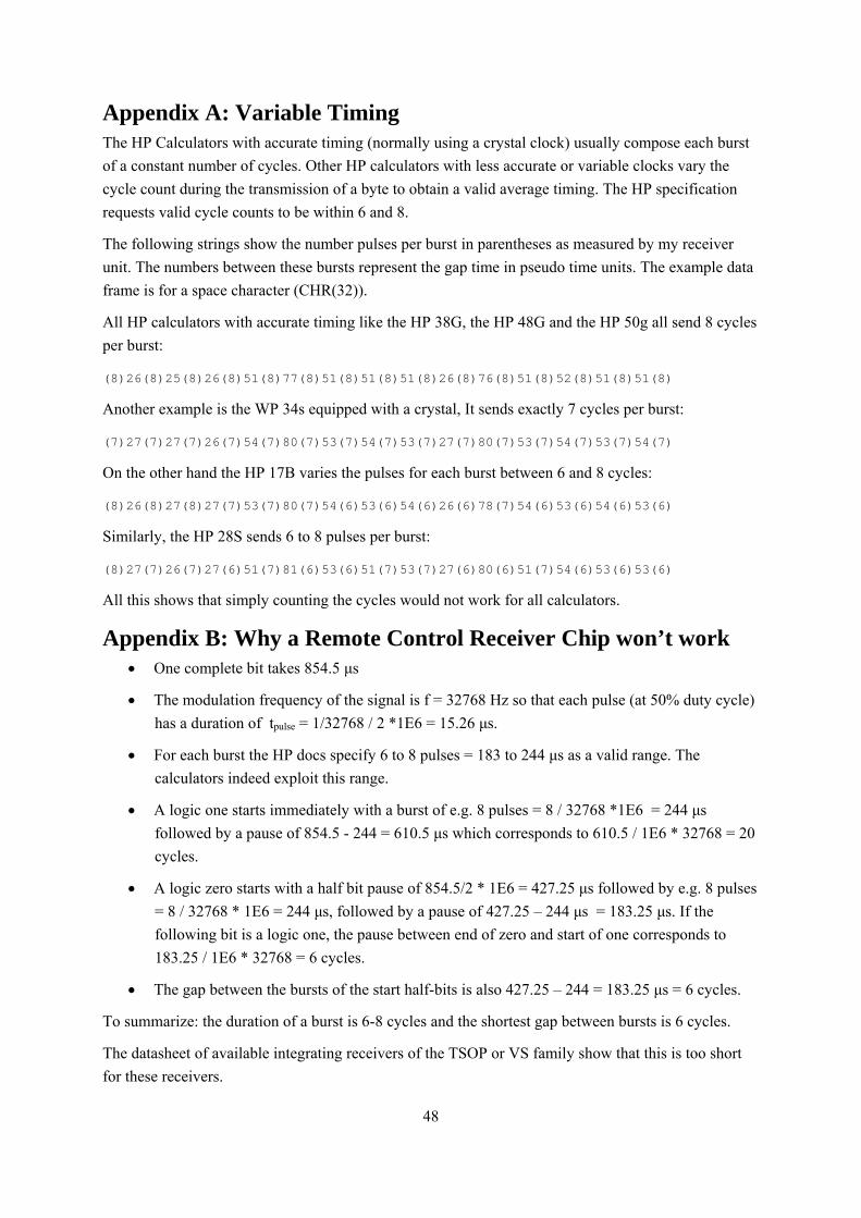
Appendix A: Variable Timing The HP Calculators with accurate timing (normally using a crystal clock) usually compose each burst
of a constant number of cycles. Other HP calculators with less accurate or variable clocks vary the
cycle count during the transmission of a byte to obtain a valid average timing. The HP specification
requests valid cycle counts to be within 6 and 8.
The following strings show the number pulses per burst in parentheses as measured by my receiver
unit. The numbers between these bursts represent the gap time in pseudo time units. The example data
frame is for a space character (CHR(32)).
All HP calculators with accurate timing like the HP 38G, the HP 48G and the HP 50g all send 8 cycles
per burst:
(8)26(8)25(8)26(8)51(8)77(8)51(8)51(8)51(8)26(8)76(8)51(8)52(8)51(8)51(8)
Another example is the WP 34s equipped with a crystal, It sends exactly 7 cycles per burst:
(7)27(7)27(7)26(7)54(7)80(7)53(7)54(7)53(7)27(7)80(7)53(7)54(7)53(7)54(7)
On the other hand the HP 17B varies the pulses for each burst between 6 and 8 cycles:
(8)26(8)27(8)27(7)53(7)80(7)54(6)53(6)54(6)26(6)78(7)54(6)53(6)54(6)53(6)
Similarly, the HP 28S sends 6 to 8 pulses per burst:
(8)27(7)26(7)27(6)51(7)81(6)53(6)51(7)53(7)27(6)80(6)51(7)54(6)53(6)53(6)
All this shows that simply counting the cycles would not work for all calculators.
Appendix B: Why a Remote Control Receiver Chip won’t work One complete bit takes 854.5 μs
The modulation frequency of the signal is f = 32768 Hz so that each pulse (at 50% duty cycle)
has a duration of tpulse = 1/32768 / 2 *1E6 = 15.26 μs.
For each burst the HP docs specify 6 to 8 pulses = 183 to 244 μs as a valid range. The
calculators indeed exploit this range.
A logic one starts immediately with a burst of e.g. 8 pulses = 8 / 32768 *1E6 = 244 μs
followed by a pause of 854.5 - 244 = 610.5 μs which corresponds to 610.5 / 1E6 * 32768 = 20
cycles.
A logic zero starts with a half bit pause of 854.5/2 * 1E6 = 427.25 μs followed by e.g. 8 pulses
= 8 / 32768 * 1E6 = 244 μs, followed by a pause of 427.25 – 244 μs = 183.25 μs. If the
following bit is a logic one, the pause between end of zero and start of one corresponds to
183.25 / 1E6 * 32768 = 6 cycles.
The gap between the bursts of the start half-bits is also 427.25 – 244 = 183.25 μs = 6 cycles.
To summarize: the duration of a burst is 6-8 cycles and the shortest gap between bursts is 6 cycles.
The datasheet of available integrating receivers of the TSOP or VS family show that this is too short
for these receivers.

49
Example: TSOP 18XX
The burst length should be 6+ pulses, which fits into the HP specs.
TSOP 18XX needs a gap of at least 9 cycles to recover after each burst
tgap > 9 / 32768 * 1E6 = 274.7 μs
This is longer than the time between the start-halfbits, so that a TSOP 18XX may smear these bits
together and that’s exactly what one can see on an oscilloscope. Therefore this receiver will not work
reliably.
Example: TSOP 11XX, 21XX, 23XX, 41XX, 43XX, 25XX, 45XX
The burst length should be 6+ pulses, which fits into the HP specs.
A burst time of at least 6/f = 6/32768 * 1E6 = 183 μs is recommended. This is at the lower limit but
within the HP specs.
However, the integrated output pulse of the TSOP 11XX has a length tout within the range
tburst – 4/f < tout < tburst + 6/f0
which means that it may be 4 cycles shorter or 6 cycles longer than the actual burst. If the output is at
the upper limit of this range, it will close the gap between two bursts. Thus these receivers are also not
useable.
Figure 32: Timing diagram taken from a TSOP data sheet.
50
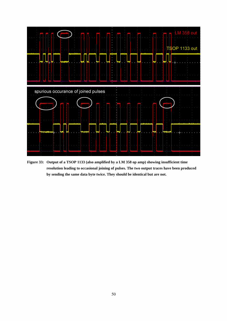
Figure 33: Output of a TSOP 1133 (also amplified by a LM 358 op amp) showing insufficient time
resolution leading to occasional joining of pulses. The two output traces have been produced
by sending the same data byte twice. They should be identical but are not.
51
The SIR Protocol
Later HP calculators and palmtop computers introduced a second infra-red protocol. The “serial over
infra-red” (SIR) protocol is a serial communications protocol. It maps the wire based serial protocol
used for RS232 links to the infra-red connection. Later this protocol was further developed into the
IrDA standard and widely used in palmtops, handhelds, printers and mobile phones
Using the same hardware of Arduino and the HP-4103A transceiver it is possible to implement this
protocol.
Due to the risk of the receiving reflections of its own transmission SIR as well as IrDA are “half
duplex”, i.e. a device can either transmit or receive, but can't do both at the same time. The initial SIR
protocol as introduced with the HP 48 used a transmission speed of 2400 baud with a tolerance of
±2.5%. IrDA requires tighter tolerances, typically in the order of less than ±1%.
The SIR signal for one data byte consists of one start bit, the 8 data bits and one or two stop bits. Thus
at least 1+8+1=10 signal bits are needed to transmit one data byte. As in the wire bound serial protocol
the 8 data bits may be replaced by 7 data bits and a parity bit, reducing the number of characters to the
classical 7-bit ASCII range from 0 to 127.
A logical zero is represented by a constant (non-modulated) pulse of IR light having a duration of 3/16
of the bit time and at least 1.6 us (which corresponds to a maximum speed of 115200 baud).
The start bit is a logical zero '0', the stop bits are logical ones '1'. Therefore stop bits are not visible at
the end of a byte but act as a pause.
The SIR Timing
The transmission speed is determined by the “baud” rate. The baud rate defines the number of bits
transmitted per time. One baud means one bit per second. The duration of one bit is therefore given by
1
bitt baudD = .
Implementation
To allow for the transfer of international characters we use 8 data bits and terminate the sequence by
two stop bits. The baud rate may be adjusted and is stored in the EEPROM of the AVR controller. For
the internal calculations and in order to minimize storage space in the EEPROM the baud rate is
specified as a reduced value of
300 300
baudbaud =
The rounded bit time in μs can then be calculated by the integer expression
300
,300
310000
23t sbi
baud
tbaudm
⋅+
D =⋅
52
The specification calls for a pulse duration of 3/16 of the bit time (or at least 1.6 μs). The rounded
duration of the pulse in μs is therefore determined by the integer expression
,
,
3 8
16
bit
p
s
sulse
tt
m
m
⋅ D +D =
Finally the remaining pause time after a pulse to fill the bit time is given by the difference
, , ,pause bit puls s sset t tm m mD = D - D
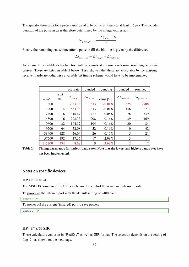
As we use the available delay function with uses units of microseconds some rounding errors are
present. These are listed in table 2 below. Tests showed that these are acceptable by the existing
receiver hardware, otherwise a variable bit timing scheme would have to be implemented.
accurate rounded rounding rounded rounded
baud 300
baud
, sbitt mD , sbitt mD error [%] ,puls set mD ,paus set mD
300 1 3333.33 3333 -0.01% 625 2708
1200 4 833.33 833 -0.04% 156 677
2400 8 416.67 417 0.08% 78 339
4800 16 208.33 208 -0.16% 39 169
9600 32 104.17 104 -0.16% 20 84
19200 64 52.08 52 -0.16% 10 42
38400 128 26.04 26 -0.16% 5 21
57600 192 17.36 17 -2.08% 3 14
115200 384 8.68 9 3.68% 2 7
Table 2: Timing parameters for various baud rates. Note that the lowest and highest baud rates have
not been implemented.
Notes on specific devices
HP 100/200LX
The MSDOS command SERCTL can be used to control the serial and infra-red ports.
To power up the infrared port with the default setting of 2400 baud:
SERCTL /I
To power off the current (infrared) port to save power:
SERCTL /O
HP 48/49/50 SIR
These calculators can print in “RedEye” as well as SIR format. The selection depends on the setting of
flag -34 as shown on the next page.
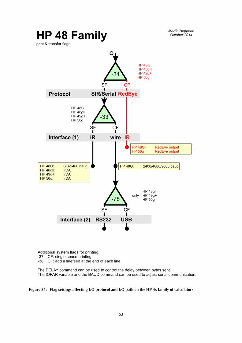
53
-34
Protocol
Interface (1)
-33
CFCFSFSF
RedEyeRedEye
IRIR
CFCFSFSF
SIR/SerialSIR/Serial
wirewireIRIR
HP 48 Familyprint & transfer flags
HP 48G: SiR/2400 baudHP 48gII: IrDAHP 49g+: IrDAHP 50g: IrDA
-78
CFCFSFSF
USBUSBRS232RS232
HP 48G: 2400/4800/9600 baud
HP 48gIIonly HP 49g+
HP 50g
Additional system flags for printing:-37 CF: single space printing,-38 CF: add a linefeed at the end of each line.
The DELAY command can be used to control the delay between bytes sent.The IOPAR variable and the BAUD command can be used to adjust serial communication.
Interface (2)
HP 48G: RedEye outputHP 50g RedEye output
HP 48GHP 48gIIHP 49g+HP 50g
HP 48GHP 48gIIHP 49g+HP 50g
Martin HepperleOctober 2014
Figure 34: Flag settings affecting I/O protocol and I/O path on the HP 4x family of calculators.