Embed Size (px)
Citation preview
Research ArticleA Heterogeneous Image Fusion Method Based on DCT andAnisotropic Diffusion for UAVs in Future 5G IoT Scenarios
Shuai Hao ,1,2 Beiyi An,2 Hu Wen ,1 Xu Ma,2 and Keping Yu 3
1College of Safety Science and Engineering, Xi’an University of Science and Technology, Xi’an 710054, China2College of Electrical and Control Engineering, Xi’an University of Science and Technology, Xi’an 710054, China3Global Information and Telecommunication Institute, Waseda University, Tokyo 169-8050, Japan
Correspondence should be addressed to Hu Wen; [email protected] and Keping Yu; [email protected]
Received 26 April 2020; Revised 8 May 2020; Accepted 27 May 2020; Published 27 June 2020
Academic Editor: Di Zhang
Copyright © 2020 Shuai Hao et al. This is an open access article distributed under the Creative Commons Attribution License,which permits unrestricted use, distribution, and reproduction in any medium, provided the original work is properly cited.
Unmanned aerial vehicles, with their inherent fine attributes, such as flexibility, mobility, and autonomy, play an increasinglyimportant role in the Internet of Things (IoT). Airborne infrared and visible image fusion, which constitutes an important databasis for the perception layer of IoT, has been widely used in various fields such as electric power inspection, militaryreconnaissance, emergency rescue, and traffic management. However, traditional infrared and visible image fusion methodssuffer from weak detail resolution. In order to better preserve useful information from source images and produce a moreinformative image for human observation or unmanned aerial vehicle vision tasks, a novel fusion method based on discretecosine transform (DCT) and anisotropic diffusion is proposed. First, the infrared and visible images are denoised by using DCT.Second, anisotropic diffusion is applied to the denoised infrared and visible images to obtain the detail and base layers. Third,the base layers are fused by using weighted averaging, and the detail layers are fused by using the Karhunen–Loeve transform,respectively. Finally, the fused image is reconstructed through the linear superposition of the base layer and detail layer.Compared with six other typical fusion methods, the proposed approach shows better fusion performance in both objective andsubjective evaluations.
1. Introduction
Internet of Things (IoT) has attracted extensive attention inacademics and industry ever since it was first proposed. IoTaims at integrating various technologies, such as bodydomain network systems, device-to-device (D2D) communi-cation, and unmanned aerial vehicles (UAVs) and satellitenetworks, to provide a wide range of services in any locationby using any network. This makes it highly useful for variouscivil and military applications. In recent years, however, theproliferation of intelligent devices used in IoT has given riseto massive amounts of data, which brings its own set of chal-lenges to the smooth functioning of the wireless communica-tion network. However, the emergence of the fifth-generation(5G) wireless communication technology has provided aneffective solution to this problem. Many scholars are commit-ted to the study of key 5G characteristics such as quality-of-
service (QoS) and connectivity [1, 2]. With the developmentof UAV technology and 5G wireless systems, the applicationfield of IoT has expanded further [3–5]. Due to their charac-teristics of dynamic deployment, convenient configuration,and high autonomy, UAVs play an extremely important rolein IoT. As some wireless devices suffer from limited trans-mission ranges, UAVs can be used as wireless relays toimprove the network connection and extend the coverageof the wireless network. Meanwhile, due to their adjustableflight altitude and mobility, UAVs can easily and efficientlycollect data from the users of IoT on the ground. At present,there exists an intelligent UAVmanagement platform, whichcan operate several UAVs at the same time through variousterminal devices. It is capable of customizing flight routesas needed and obtaining the required user data. Intelligenttransportation systems (ITS) can use UAVs for traffic moni-toring and law enforcement. UAVs can also be used as base
HindawiWireless Communications and Mobile ComputingVolume 2020, Article ID 8816818, 11 pageshttps://doi.org/10.1155/2020/8816818
stations in the air to improve wireless network capacity. In5G IoT, UAV wireless communication systems will play anincreasingly important role [6, 7].
The perception layer, which is the basic layer of IoT, con-sists of different sensors. The UAVs collect the data of IoTusers by means of airborne IoT devices, including infrared(IR) cameras and visible (VI) light cameras [8]. One of thekey technologies affecting the reliability of the perceptionlayer is the accurate acquisition of multisource signals andreliable fusion of data. In recent years, heterogeneous imagefusion has become an important topic regarding the percep-tion layer of IoT. IR and visible light sensors are the two mostcommonly used types of sensors. IR images taken by an IRsensor are usually less affected by adverse weather condi-tions such as bright sunlight and smog [9]. However, IRimages lack sufficient details of the scene and have a lowerspatial resolution than VI images. In contrast, VI imagescontain more detailed scene information, but are easilyaffected by illumination variation. IR and VI image fusioncould produce a composite image, which is more interpret-able to both human and machine perception. The goal ofimage fusion is to combine images obtained by differenttypes of image sensors to generate an informative image.The fused image would be more consistent with the humanvisual perception system than the source image individu-ally. It can be convenient for subsequent processing ordecision-making. Nowadays, the image fusion technique iswidely used in such fields as military reconnaissance [10],traffic management [11], medical treatment [12], andremote sensing [13, 14].
In recent decades, a variety of IR and VI image fusionapproaches have been investigated. In general, based on thedifferent levels of image representation, fusion methodscould be classified into three categories: pixel-level, feature-level, and decision-level [15]. Pixel-level fusion, conductedon raw source images, usually generates more accurate,richer, and reliable details compared with other fusionmethods. Feature-level image fusion first extracts various fea-tures (including colour, shape, and edge) from the multi-source information of different sensors. Subsequently, thefeature information obtained from multiple sensors is ana-lysed and processed synthetically. Although this methodcould reduce the amount of data and retain most of the infor-mation, some details of the image are still lost. Decision-levelfusion is used to fuse the recognition results of multiple sen-sors to make a global optimal decision on the basis of eachsensor independently, thus, completing the decision or classi-fication. Decision-level fusion has the advantage of good real-time performance, self-adaptability, and strong anti-interference; however, the fault-tolerance ability of the deci-sion function directly affects the fusion classification perfor-mance. In this study, we focus on the pixel-level fusionmethod.
The remainder of this paper is organised as follows. InSection 2, we introduce related works and the motivationbehind the present work. The proposed fusion method isdescribed in Section 3. Experimental results on public data-sets are covered in Section 4. The conclusions of this studyare presented in Section 5.
2. Related Works
In general, the pixel-level fusion approach can be dividedinto two categories: space-based fusion methods and thetransform domain technique. Space-based fusion methodsusually address the fusion issue via pixel grayscale or pixelgradient. Although these methods are simple and effective,they easily lose spatial details [16]. Liu et al. [17] observedthat this type of method is more suitable to fusion tasks ofthe same type of images. The transform domain techniqueusually takes the transform coefficient as the feature forimage fusion. The fused image is obtained by the fusionand reconstruction of the transform coefficients. The imagefusion method based on multiscale transformation has beenwidely investigated because of its compatibility with humanvisual perception. In recent years, a variety of fusion methodsbased on multiscale transform have been proposed, such aslow-pass pyramid (RP) [18], gradient pyramid (GP) [19],nonsubsampled contourlet transform (NSCT) [20], discretewavelet transform (DWT) [21], and dual-tree complex wave-let transform (DTCWT) [22]. However, image fusionmethods based on multiscale transform are usually complexand suffer from long processing time and energy consump-tion issues, which limit their application.
Due to the aforementioned reasons, many researchersimplemented image fusion methods by using discrete cosinetransform (DCT). In [23], the authors pointed out that imagefusion methods based on DCT were efficient due to their fastspeed and low complexity. Cao et al. [24] proposed a multi-focus image fusion algorithm based on spatial frequency inthe DCT domain. The experimental results showed that itcould improve the quality of the output image visually.Amin-Naji and Aghagolzadeh et al. [25] employed the corre-lation coefficient in the DCT domain for multifocus imagefusion, proving that the proposed method could improveimage quality and stability in noisy images. In order to pro-vide better visual effects, Jin et al. [26] proposed a heteroge-neous image fusion method by combining DSWT, DCT,and LSF. Jin et al. proved that the proposed method wassuperior to the conventional multiscale method. Althoughimage fusion methods based on DCT have achieved superiorperformance, the fused results show undesirable side effectssuch as blocking artifacts [27]. While performing DCT, theimage is usually required to be divided into small blocksprior, which causes discontinuities between adjacent blocksin the image. In order to address this problem, several filter-ing techniques have been proposed, such as weighted leastsquare filter [28], bilateral filter [29], and anisotropic diffu-sion filter [30]. Xie andWang [31] pointed out that the aniso-tropic diffusion processing of images could retain the imageedge contour information. Compared with other fusionmethods based on filtering, image fusion based on aniso-tropic diffusion could retain more edge profiles. It preferablysuppresses noise and obtains better visual evaluation. How-ever, most of the proposed methods for anisotropic diffusionmodels are based on the diffusion equation itself, ignoring theimage’s own feature information, which may lead to loss orblurring of image details (textures, weak edges, etc.). Inspiredby the above research, a heterogeneous image fusion method
2 Wireless Communications and Mobile Computing
based on DCT and anisotropic diffusion is proposed. Theadvantages of the proposed method mainly lie in the follow-ing three aspects:
(1) Due to the use of DCT transform, the fusion algo-rithm proposed in this paper shows good denoisingability
(2) The final fusion images show satisfactory detailresolution
(3) The proposed algorithm is easy to implement, andthe real-time performance is very good, which is suit-able for real-time requirements
3. Proposed Fusion Method
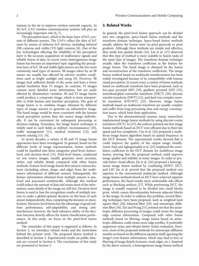
In this section, the operation mechanism of the proposedalgorithm is described in detail. The proposed image fusionframework can be divided into three components, as shownin Figure 1. In the first step, in order to eliminate the noisein the original images, DCT and inverse discrete cosine trans-form are performed on the IR and VI images, respectively. Inthe second step, anisotropic diffusion is adopted todecompose IR and VI images to obtain the detail and baselayers. In the third step, base layers are fused by using theweighted averaging, and detail layers are fused by using theKarhunen–Loeve transformation. Finally, the fused baseand detail layers are linearly superimposed to obtain the finalfusion result.
3.1. DCT. As an effective transform tool, DCT can transformthe image information from the time domain to the fre-quency domain so as to effectively reduce the spatial redun-dancy of the image. In this study, the 2D DCT of an N ×N
image block f ði, jÞ is defined as follows [32]:
F u, vð Þ = 2Nc uð Þc vð Þ 〠
N−1
i=0〠N−1
j=0f i, jð Þ cos 2i + 1ð Þπu
2N
� �
× cos2j + 1ð Þπv
2N
� �, where u, v = 0, 1,⋯N − 1,
ð1Þ
where f ði, jÞ denotes the ði, jÞ‐th image pixel value in the spa-tial domain and Fðu, vÞ denotes the ði, jÞ‐th DCT coefficientin the frequency domain; cðkÞ is a multiplication factor,defined as follows:
c kð Þ =1ffiffiffi2
p , if u = 0,
1 if u ≠ 0:
8><>: ð2Þ
Similarly, the 2D inverse discrete cosine transform(IDCT) is defined as:
f i, jð Þ = 2N
〠N−1
u=0〠N−1
v=0c uð Þc vð ÞF u, vð Þ cos 2i + 1ð Þπu
2N
� �
× cos2j + 1ð Þπv
2N
� �, where i, j = 0, 1,⋯N − 1:
ð3Þ
When performing the DCT transform, most of the imageinformation is concentrated on the DC coefficient and low-frequency spectrum nearby. Therefore, the coefficient closeto 0 is deleted, and the coefficient containing the main infor-mation of the image is reserved for inverse transformation.The influence of noise can be effectively removed without
Baselayer
Baselayer
Detaillayer
Detaillayer
Weightedaverage
KLtransform
fusion
Anisotropicdiffusion
Anisotropicdiffusion
Quantification
Quantification
DCT
DCT
8⁎8blocks
8⁎8blocks
DCTcoefficients
DCTcoefficients
IDCT
IDCT
Final fusedimage
Step1: DCT denoising Step2: anisotropic diffusion Step3: fusion andreconstruction
Linearsuperposition
Infrared image
Visible image
Figure 1: Flowchart of the proposed method framework.
3Wireless Communications and Mobile Computing
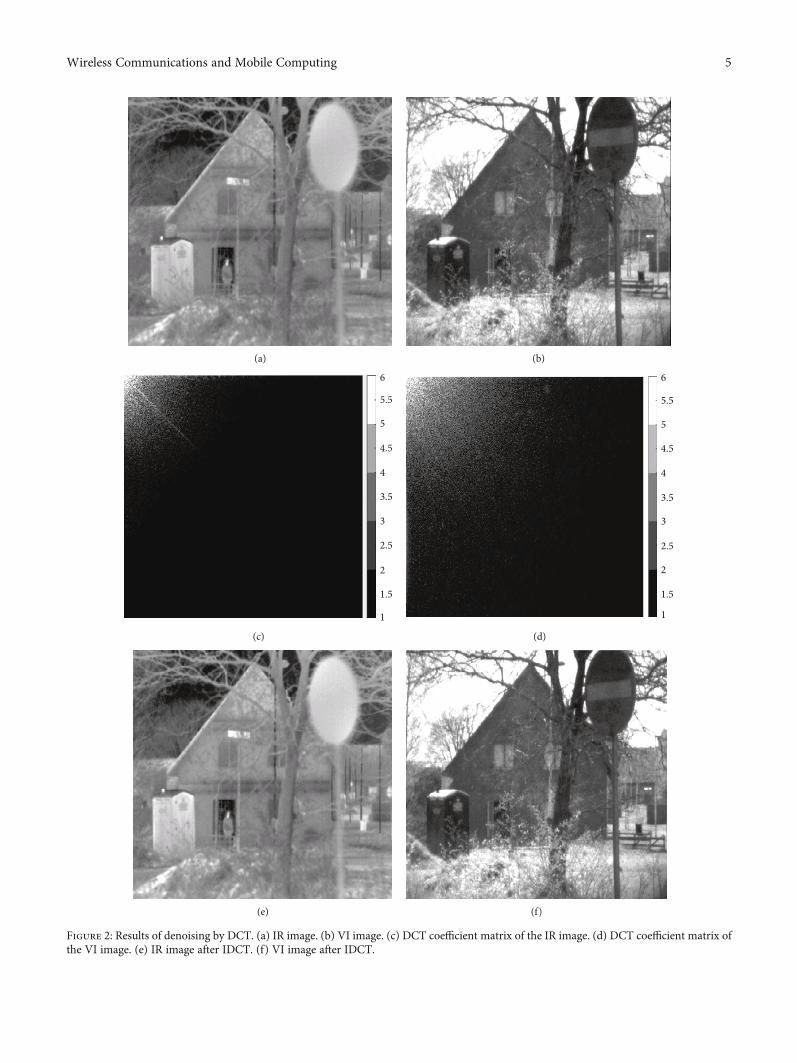
causing image distortion. In this study, if the coefficientobtained by the DCT transformation is less than 0.1, we setthe coefficient as 0. The results of denoising by DCT areshown in Figure 2.
3.2. Anisotropic Diffusion. In computer vision, anisotropicdiffusion is widely used to reduce noise while preservingimage details. The model of anisotropic diffusion of an imageI can be represented as follows [33]:
It = c x, y, tð ÞΔI + ∇c ⋅ ∇I, ð4Þ
where cðx, y, tÞis rate of diffusion, ∇and Δ are used to repre-sent the gradient operator and the Laplacian operator,respectively, and t is time. Then, the equation (4) can be dis-cretized as:
It+1i,j = Iti, j + λ cN ⋅ΩNIti,j + cS ⋅ΩSI
ti,j + cE ⋅ΩEI
ti,j + cW ⋅ΩWIti,j
h i:
ð5Þ
In (5), It+1i,j is an image with coarse resolution at t + 1scale. λ denotes a stability constant satisfying 0 ≤ λ ≤ 1/4.The local image gradients along the north, south, east, andwest directions are represented as:
ΩNIi,j = Ii−1,j − Ii,j,
ΩSIi,j = Ii+1,j − Ii,j,
ΩEIi,j = Ii,j+1 − Ii,j,
ΩWIi,j = Ii,j−1 − Ii,j:
8>>>>><>>>>>:
ð6Þ
Similarly, the conduction coefficients along the fourdirections of north, south, east, and west can be defined as:
ctNi, j= g ∇Ið Þti+1/2,j
��� ���� �= g ΩNI
ti,j
��� ���� �,
ctSi, j = g ∇Ið Þti−1/2,j��� ���� �
= g ΩSIti,j
��� ���� �,
ctEi, j= g ∇Ið Þti,j+1/2
��� ���� �= g ΩEI
ti,j
��� ���� �,
ctWi, j= g ∇Ið Þti,j−1/2
��� ���� �= g ΩWIti,j
��� ���� �:
8>>>>>>>>>><>>>>>>>>>>:
ð7Þ
In (7), gð·Þ is a decreasing function. In order to maintainsmoothing and edge preservation, in this paper, we choosegð·Þ as:
g ∇Ið Þ =1 −
∇Ik kð Þ2T2
" #2
, ∇Ik kð Þ2 ≤ T2,
0, ∇Ik kð Þ2 > T2,
8>><>>: ð8Þ
where T is an edge magnitude parameter.Let IIRðx, yÞ and IVIðx, yÞ be IR and VI images, respec-
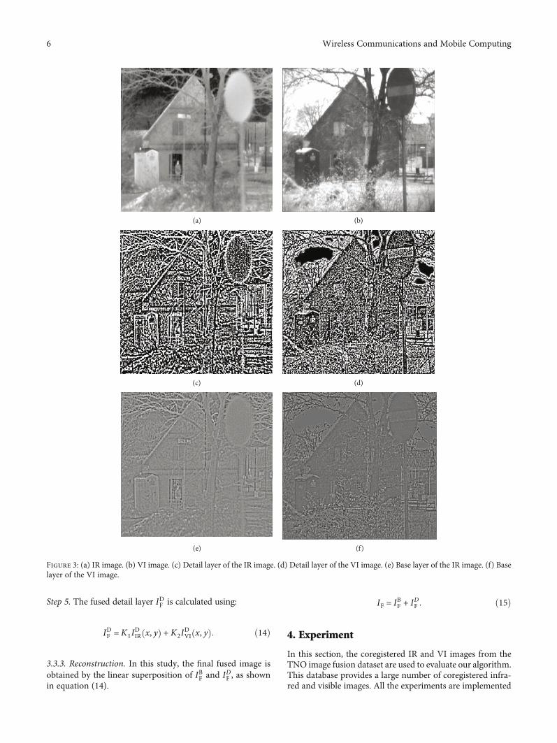
tively, which have been coregistered. Anisotropic diffusionfor an image Iis denoted as ADðIÞ. The base layers IBIRðx, yÞ
and IBVIðx, yÞ are obtained after performing anisotropic diffu-sion processes on IIRðx, yÞ and IVIðx, yÞ, respectively, whichare represented by:
IBIR x, yð Þ = AD IIR x, yð Þð Þ,IBVI x, yð Þ = AD IVI x, yð Þð Þ:
(ð9Þ
Then, the detail layers IDIRðx, yÞ and IDVIðx, yÞ are obtainedby subtracting the base layers from the respective sourceimages, which are shown in (10).
IDIR x, yð Þ = IIR x, yð Þ‐IBIR x, yð Þ,IDVI x, yð Þ = IVI x, yð Þ‐IBVI x, yð Þ:
(ð10Þ
The results obtained by the anisotropic diffusion of IRimage and VI image are shown in Figure 3.
3.3. Construction and Fusion
3.3.1. Base Layer Fusion. The weighted average is adopted tofuse the base layers of IR and VI images. The fused base layerIBF is calculated by:
IBF = ω1IBIR x, yð Þ + ω2I
BVI x, yð Þ, ð11Þ
where ω1 and ω2are normalized weighted coefficients, setto 0.5 in this paper.
3.3.2. Detail Layer Fusion. KL-transform can make the newsample set approximate to the original sample set distribu-tion with minimum mean square error, and it eliminatesthe correlation between the original features. We use KL-transform to fuse the detail layers of IR and VI images. LetIDIRðx, yÞ and IDVIðx, yÞ be detail layers of the IR and VI images,respectively. The fused process based on KL-transform isdescribed as follows.
Step 1. Arrange IDIRðx, yÞ and IDVIðx, yÞ as column vectors of amatrix, denoted as X.
Step 2. Calculate the autocorrelation matrix C of X.
Step 3. Calculate the eigenvalues λ1 matrix λ2, and eigenvec-tors μ1 = ½μ1ð1Þ μ1ð2Þ�T and μ2 = ½μ2ð1Þμ2ð2Þ�T of C.
Step 4. Calculate the uncorrelated coefficients K1 and K2 cor-responding to the largest eigenvalue λmax, which is defined as:
λmax = max λ1, λ2ð Þ: ð12Þ
The eigenvector corresponding to λmax is denoted as μmax. And, K1 and K2 are given by:
K1 = λmax 1ð Þ/〠i
λmax ið Þ,
K2 = λmax 2ð Þ/〠i
λmax ið Þ:
8>><>>: ð13Þ
4 Wireless Communications and Mobile Computing
(a) (b)
6
5.5
5
4.5
4
3.5
3
2.5
2
1.5
1
(c)
6
5.5
5
4.5
4
3.5
3
2.5
2
1.5
1
(d)
(e) (f)
Figure 2: Results of denoising by DCT. (a) IR image. (b) VI image. (c) DCT coefficient matrix of the IR image. (d) DCT coefficient matrix ofthe VI image. (e) IR image after IDCT. (f) VI image after IDCT.
5Wireless Communications and Mobile Computing
Step 5. The fused detail layer IDF is calculated using:
IDF = K1IDIR x, yð Þ + K2I
DVI x, yð Þ: ð14Þ
3.3.3. Reconstruction. In this study, the final fused image isobtained by the linear superposition of IBF and IDF , as shownin equation (14).
IF = IBF + IDF : ð15Þ
4. Experiment
In this section, the coregistered IR and VI images from theTNO image fusion dataset are used to evaluate our algorithm.This database provides a large number of coregistered infra-red and visible images. All the experiments are implemented
(a) (b)
(c) (d)
(e) (f)
Figure 3: (a) IR image. (b) VI image. (c) Detail layer of the IR image. (d) Detail layer of the VI image. (e) Base layer of the IR image. (f) Baselayer of the VI image.
6 Wireless Communications and Mobile Computing
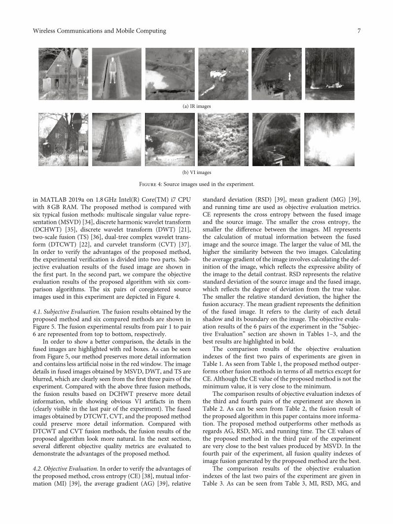
in MATLAB 2019a on 1.8GHz Intel(R) Core(TM) i7 CPUwith 8GB RAM. The proposed method is compared withsix typical fusion methods: multiscale singular value repre-sentation (MSVD) [34], discrete harmonic wavelet transform(DCHWT) [35], discrete wavelet transform (DWT) [21],two-scale fusion (TS) [36], dual-tree complex wavelet trans-form (DTCWT) [22], and curvelet transform (CVT) [37].In order to verify the advantages of the proposed method,the experimental verification is divided into two parts. Sub-jective evaluation results of the fused image are shown inthe first part. In the second part, we compare the objectiveevaluation results of the proposed algorithm with six com-parison algorithms. The six pairs of coregistered sourceimages used in this experiment are depicted in Figure 4.
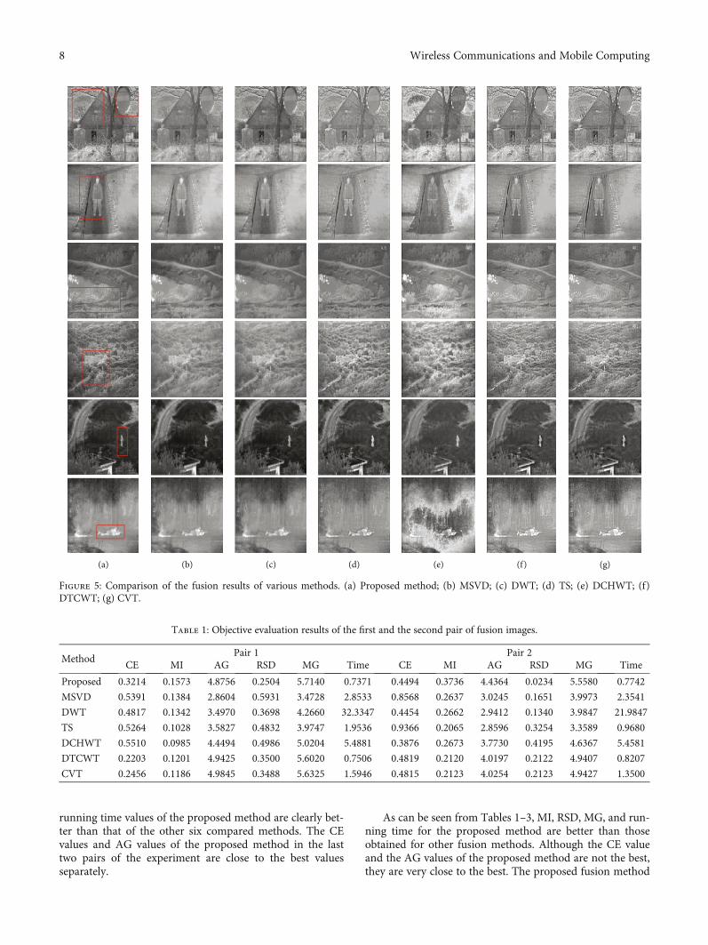
4.1. Subjective Evaluation. The fusion results obtained by theproposed method and six compared methods are shown inFigure 5. The fusion experimental results from pair 1 to pair6 are represented from top to bottom, respectively.
In order to show a better comparison, the details in thefused images are highlighted with red boxes. As can be seenfrom Figure 5, our method preserves more detail informationand contains less artificial noise in the red window. The imagedetails in fused images obtained by MSVD, DWT, and TS areblurred, which are clearly seen from the first three pairs of theexperiment. Compared with the above three fusion methods,the fusion results based on DCHWT preserve more detailinformation, while showing obvious VI artifacts in them(clearly visible in the last pair of the experiment). The fusedimages obtained by DTCWT, CVT, and the proposed methodcould preserve more detail information. Compared withDTCWT and CVT fusion methods, the fusion results of theproposed algorithm look more natural. In the next section,several different objective quality metrics are evaluated todemonstrate the advantages of the proposed method.
4.2. Objective Evaluation. In order to verify the advantages ofthe proposed method, cross entropy (CE) [38], mutual infor-mation (MI) [39], the average gradient (AG) [39], relative
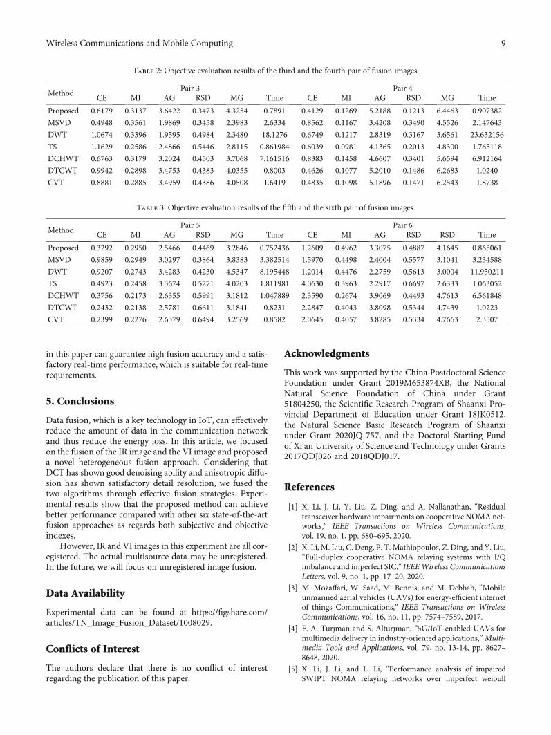
standard deviation (RSD) [39], mean gradient (MG) [39],and running time are used as objective evaluation metrics.CE represents the cross entropy between the fused imageand the source image. The smaller the cross entropy, thesmaller the difference between the images. MI representsthe calculation of mutual information between the fusedimage and the source image. The larger the value of MI, thehigher the similarity between the two images. Calculatingthe average gradient of the image involves calculating the def-inition of the image, which reflects the expressive ability ofthe image to the detail contrast. RSD represents the relativestandard deviation of the source image and the fused image,which reflects the degree of deviation from the true value.The smaller the relative standard deviation, the higher thefusion accuracy. The mean gradient represents the definitionof the fused image. It refers to the clarity of each detailshadow and its boundary on the image. The objective evalu-ation results of the 6 pairs of the experiment in the “Subjec-tive Evaluation” section are shown in Tables 1–3, and thebest results are highlighted in bold.
The comparison results of the objective evaluationindexes of the first two pairs of experiments are given inTable 1. As seen from Table 1, the proposed method outper-forms other fusion methods in terms of all metrics except forCE. Although the CE value of the proposed method is not theminimum value, it is very close to the minimum.
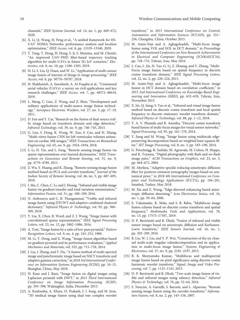
The comparison results of objective evaluation indexes ofthe third and fourth pairs of the experiment are shown inTable 2. As can be seen from Table 2, the fusion result ofthe proposed algorithm in this paper contains more informa-tion. The proposed method outperforms other methods asregards AG, RSD, MG, and running time. The CE values ofthe proposed method in the third pair of the experimentare very close to the best values produced by MSVD. In thefourth pair of the experiment, all fusion quality indexes ofimage fusion generated by the proposed method are the best.
The comparison results of the objective evaluationindexes of the last two pairs of the experiment are given inTable 3. As can be seen from Table 3, MI, RSD, MG, and
(a) IR images
(b) VI images
Figure 4: Source images used in the experiment.
7Wireless Communications and Mobile Computing
running time values of the proposed method are clearly bet-ter than that of the other six compared methods. The CEvalues and AG values of the proposed method in the lasttwo pairs of the experiment are close to the best valuesseparately.
As can be seen from Tables 1–3, MI, RSD, MG, and run-ning time for the proposed method are better than thoseobtained for other fusion methods. Although the CE valueand the AG values of the proposed method are not the best,they are very close to the best. The proposed fusion method
(a) (b) (c) (d) (e) (f) (g)
Figure 5: Comparison of the fusion results of various methods. (a) Proposed method; (b) MSVD; (c) DWT; (d) TS; (e) DCHWT; (f)DTCWT; (g) CVT.
Table 1: Objective evaluation results of the first and the second pair of fusion images.
MethodPair 1 Pair 2
CE MI AG RSD MG Time CE MI AG RSD MG Time
Proposed 0.3214 0.1573 4.8756 0.2504 5.7140 0.7371 0.4494 0.3736 4.4364 0.0234 5.5580 0.7742
MSVD 0.5391 0.1384 2.8604 0.5931 3.4728 2.8533 0.8568 0.2637 3.0245 0.1651 3.9973 2.3541
DWT 0.4817 0.1342 3.4970 0.3698 4.2660 32.3347 0.4454 0.2662 2.9412 0.1340 3.9847 21.9847
TS 0.5264 0.1028 3.5827 0.4832 3.9747 1.9536 0.9366 0.2065 2.8596 0.3254 3.3589 0.9680
DCHWT 0.5510 0.0985 4.4494 0.4986 5.0204 5.4881 0.3876 0.2673 3.7730 0.4195 4.6367 5.4581
DTCWT 0.2203 0.1201 4.9425 0.3500 5.6020 0.7506 0.4819 0.2120 4.0197 0.2122 4.9407 0.8207
CVT 0.2456 0.1186 4.9845 0.3488 5.6325 1.5946 0.4815 0.2123 4.0254 0.2123 4.9427 1.3500
8 Wireless Communications and Mobile Computing
in this paper can guarantee high fusion accuracy and a satis-factory real-time performance, which is suitable for real-timerequirements.
5. Conclusions
Data fusion, which is a key technology in IoT, can effectivelyreduce the amount of data in the communication networkand thus reduce the energy loss. In this article, we focusedon the fusion of the IR image and the VI image and proposeda novel heterogeneous fusion approach. Considering thatDCT has shown good denoising ability and anisotropic diffu-sion has shown satisfactory detail resolution, we fused thetwo algorithms through effective fusion strategies. Experi-mental results show that the proposed method can achievebetter performance compared with other six state-of-the-artfusion approaches as regards both subjective and objectiveindexes.
However, IR and VI images in this experiment are all cor-egistered. The actual multisource data may be unregistered.In the future, we will focus on unregistered image fusion.
Data Availability
Experimental data can be found at https://figshare.com/articles/TN_Image_Fusion_Dataset/1008029.
Conflicts of Interest
The authors declare that there is no conflict of interestregarding the publication of this paper.
Acknowledgments
This work was supported by the China Postdoctoral ScienceFoundation under Grant 2019M653874XB, the NationalNatural Science Foundation of China under Grant51804250, the Scientific Research Program of Shaanxi Pro-vincial Department of Education under Grant 18JK0512,the Natural Science Basic Research Program of Shaanxiunder Grant 2020JQ-757, and the Doctoral Starting Fundof Xi’an University of Science and Technology under Grants2017QDJ026 and 2018QDJ017.
References
[1] X. Li, J. Li, Y. Liu, Z. Ding, and A. Nallanathan, “Residualtransceiver hardware impairments on cooperative NOMA net-works,” IEEE Transactions on Wireless Communications,vol. 19, no. 1, pp. 680–695, 2020.
[2] X. Li, M. Liu, C. Deng, P. T. Mathiopoulos, Z. Ding, and Y. Liu,“Full-duplex cooperative NOMA relaying systems with I/Qimbalance and imperfect SIC,” IEEEWireless CommunicationsLetters, vol. 9, no. 1, pp. 17–20, 2020.
[3] M. Mozaffari, W. Saad, M. Bennis, and M. Debbah, “Mobileunmanned aerial vehicles (UAVs) for energy-efficient internetof things Communications,” IEEE Transactions on WirelessCommunications, vol. 16, no. 11, pp. 7574–7589, 2017.
[4] F. A. Turjman and S. Alturjman, “5G/IoT-enabled UAVs formultimedia delivery in industry-oriented applications,”Multi-media Tools and Applications, vol. 79, no. 13-14, pp. 8627–8648, 2020.
[5] X. Li, J. Li, and L. Li, “Performance analysis of impairedSWIPT NOMA relaying networks over imperfect weibull
Table 2: Objective evaluation results of the third and the fourth pair of fusion images.
MethodPair 3 Pair 4
CE MI AG RSD MG Time CE MI AG RSD MG Time
Proposed 0.6179 0.3137 3.6422 0.3473 4.3254 0.7891 0.4129 0.1269 5.2188 0.1213 6.4463 0.907382
MSVD 0.4948 0.3561 1.9869 0.3458 2.3983 2.6334 0.8562 0.1167 3.4208 0.3490 4.5526 2.147643
DWT 1.0674 0.3396 1.9595 0.4984 2.3480 18.1276 0.6749 0.1217 2.8319 0.3167 3.6561 23.632156
TS 1.1629 0.2586 2.4866 0.5446 2.8115 0.861984 0.6039 0.0981 4.1365 0.2013 4.8300 1.765118
DCHWT 0.6763 0.3179 3.2024 0.4503 3.7068 7.161516 0.8383 0.1458 4.6607 0.3401 5.6594 6.912164
DTCWT 0.9942 0.2898 3.4753 0.4383 4.0355 0.8003 0.4626 0.1077 5.2010 0.1486 6.2683 1.0240
CVT 0.8881 0.2885 3.4959 0.4386 4.0508 1.6419 0.4835 0.1098 5.1896 0.1471 6.2543 1.8738
Table 3: Objective evaluation results of the fifth and the sixth pair of fusion images.
MethodPair 5 Pair 6
CE MI AG RSD MG Time CE MI AG RSD RSD Time
Proposed 0.3292 0.2950 2.5466 0.4469 3.2846 0.752436 1.2609 0.4962 3.3075 0.4887 4.1645 0.865061
MSVD 0.9859 0.2949 3.0297 0.3864 3.8383 3.382514 1.5970 0.4498 2.4004 0.5577 3.1041 3.234588
DWT 0.9207 0.2743 3.4283 0.4230 4.5347 8.195448 1.2014 0.4476 2.2759 0.5613 3.0004 11.950211
TS 0.4923 0.2458 3.3674 0.5271 4.0203 1.811981 4.0630 0.3963 2.2917 0.6697 2.6333 1.063052
DCHWT 0.3756 0.2173 2.6355 0.5991 3.1812 1.047889 2.3590 0.2674 3.9069 0.4493 4.7613 6.561848
DTCWT 0.2432 0.2138 2.5781 0.6611 3.1841 0.8231 2.2847 0.4043 3.8098 0.5344 4.7439 1.0223
CVT 0.2399 0.2276 2.6379 0.6494 3.2569 0.8582 2.0645 0.4057 3.8285 0.5334 4.7663 2.3507
9Wireless Communications and Mobile Computing
channels,” IEEE Systems Journal, vol. 14, no. 1, pp. 669–672,2020.
[6] X. Li, Q. Wang, H. Peng et al., “A unified framework for HS-UAV NOMA Networks: performance analysis and locationoptimization,” IEEE Access, vol. 8, pp. 13329–13340, 2020.
[7] T. Tang, T. Hong, H. Hong, S. Ji, S. Mumtaz, and M. Cheriet,“An improved UAV-PHD filter-based trajectory trackingalgorithm for multi-UAVs in future 5G IoT scenarios,” Elec-tronics, vol. 8, no. 10, pp. 1188–1203, 2019.
[8] H. Li, S. Liu, Q. Duan, and W. Li, “Application of multi-sensorimage fusion of internet of things in image processing,” IEEEAccess, vol. 6, pp. 50776–50787, 2018.
[9] H. Shakhatreh, A. Sawalmeh, A. Al-Fuqaha et al., “Unmannedaerial vehicles (UAVs): a survey on civil applications and keyresearch challenges,” IEEE Access, vol. 7, pp. 48572–48634,2019.
[10] L. Meng, C. Liao, Z. Wang, and Z. Shen, “Development andmilitary applications of multi-source image fusion technol-ogy,” Aerospace Electronic Warfare, vol. 27, no. 3, pp. 17–19,2011.
[11] D. Fan and Y. Cai, “Research on the fusion of dual-source traf-fic image based on transform domain and edge detection,”Infrared Technology, vol. 39, no. 9, pp. 740–745, 2015.
[12] G. Luo, S. Dong, K. Wang, W. Zuo, S. Cao, and H. Zhang,“Multi-views fusion CNN for left ventricular volumes estima-tion on cardiac MR images,” IEEE Transactions on BiomedicalEngineering, vol. 65, no. 9, pp. 1924–1934, 2018.
[13] S. Li, H. Yin, and L. Fang, “Remote sensing image fusion viasparse representations over learned dictionaries,” IEEE Trans-actions on Geoscience and Remote Sensing, vol. 51, no. 9,pp. 4779–4789, 2013.
[14] Z.Wu, Y. Huang, and K. Zhang, “Remote sensing image fusionmethod based on PCA and curvelet transform,” Journal of theIndian Society of Remote Sensing, vol. 46, no. 5, pp. 687–695,2018.
[15] J. Ma, C. Chen, C. Li, and J. Huang, “Infrared and visible imagefusion via gradient transfer and total variation minimization,”Information Fusion, vol. 31, pp. 100–109, 2016.
[16] N. Aishwarya and C. B. Thangammal, “Visible and infraredimage fusion using DTCWT and adaptive combined clustereddictionary,” Infrared Physics & Technology, vol. 93, pp. 300–309, 2018.
[17] Y. Liu, X. Chen, R. Ward, and Z. J. Wang, “Image fusion withconvolutional sparse representation,” IEEE Signal ProcessingLetters, vol. 23, no. 12, pp. 1882–1886, 2016.
[18] A. Toet, “Image fusion by a ratio of low-pass pyramid,” PatternRecognition Letters, vol. 9, no. 4, pp. 245–253, 1989.
[19] M. Li, Y. Dong, and X. Wang, “Image fusion algorithm basedon gradient pyramid and its performance evaluation,” AppliedMechanics and Materials, vol. 525, pp. 715–718, 2014.
[20] J. Liu, J. Zhang, and Y. Du, “A fusion method of multi-spectralimage and panchromatic image based on NSCT transform andadaptive gamma correction,” in 2018 3rd International Confer-ence on Information Systems Engineering (ICISE), pp. 10–15,Shanghai, China, May 2018.
[21] H. Kaur and J. Rani, “Image fusion on digital images usingLaplacian pyramid with DWT,” in 2015 Third InternationalConference on Image Information Processing (ICIIP),pp. 393–398, Waknaghat, India, December 2015.
[22] A. Kushwaha, A. Khare, O. Prakash, J. I. Song, and M. Jeon,“3D medical image fusion using dual tree complex wavelet
transform,” in 2015 International Conference on Control,Automation and Information Sciences (ICCAIS), pp. 251–256, Changshu, China, October 2015.
[23] M. Amin-Naji and A. Aghagolzadeh, “Multi-focus imagefusion using VOL and EOL in DCT domain,” in Proceedingsof the International Conference on New Research Achievementsin Electrical and Computer Engineering (ICNRAECE’16),pp. 728–733, Tehran, Iran, May 2016.
[24] L. Cao, L. Jin, H. Tao, G. Li, Z. Zhuang, and Y. Zhang, “Multi-Focus image fusion based on spatial frequency in discretecosine transform domain,” IEEE Signal Processing Letters,vol. 22, no. 2, pp. 220–224, 2015.
[25] M. Amin-Naji and A. Aghagolzadeh, “Multi-focus imagefusion in DCT domain based on correlation coefficient,” in2015 2nd International Conference on Knowledge-Based Engi-neering and Innovation (KBEI), pp. 632–639, Tehran, Iran,November 2015.
[26] X. Jin, Q. Jiang, S. Yao et al., “Infrared and visual image fusionmethod based on discrete cosine transform and local spatialfrequency in discrete stationary wavelet transform domain,”Infrared Physics & Technology, vol. 88, pp. 1–12, 2018.
[27] Y. A. V. Phamila and R. Amutha, “Discrete cosine transformbased fusion of multi-focus images for visual sensor networks,”Signal Processing, vol. 95, pp. 161–170, 2014.
[28] Y. Jiang and M. Wang, “Image fusion using multiscale edge-preserving decomposition based on weighted least squares fil-ter,” IET Image Processing, vol. 8, no. 3, pp. 183–190, 2014.
[29] G. Petschnigg, R. Szeliski, M. Agrawala, M. Cohen, H. Hoppe,and K. Toyama, “Digital photography with flash and no-flashimage pairs,” ACM Transactions on Graphics, vol. 23, no. 3,pp. 664–672, 2004.
[30] M. Alrefaya, “Adaptive speckle reducing anisotropic diffusionfilter for positron emission tomography images based on ana-tomical prior,” in 2018 4th International Conference on Com-puter and Technology Applications (ICCTA), pp. 194–201,Istanbul, Turkey, May 2018.
[31] M. Xie and Z. Wang, “Edge-directed enhancing based aniso-tropic diffusion denoising,” Acta Electronica Sinica, vol. 34,no. 1, pp. 59–64, 2006.
[32] E. Vakaimalar, K. Mala, and S. R. Babu, “Multifocus imagefusion scheme based on discrete cosine transform and spatialfrequency,” Multimedia Tools and Applications, vol. 78,no. 13, pp. 17573–17587, 2019.
[33] D. P. Bavirisetti and R. Dhuli, “Fusion of infrared and visiblesensor images based on anisotropic diffusion and Karhunen-Loeve transform,” IEEE Sensors Journal, vol. 16, no. 1,pp. 203–209, 2016.
[34] B. Liu, W. J. Liu, and Y. P. Wei, “Construction of the six chan-nel multi-scale singular valuedecomposition and its applica-tion in multi-focus image fusion,” Systems Engineering &Electronics, vol. 37, no. 9, pp. 2191–2197, 2015.
[35] B. K. Shreyamsha Kumar, “Multifocus and multispectralimage fusion based on pixel significance using discrete cosineharmonic wavelet transform,” Signal, Image and Video Pro-cessing, vol. 7, pp. 1125–1143, 2013.
[36] D. P. Bavirisetti and R. Dhuli, “Two-scale image fusion of vis-ible and infrared images using saliency detection,” InfraredPhysics & Technology, vol. 76, pp. 52–64, 2016.
[37] F. Nencini, A. Garzelli, S. Baronti, and L. Alparone, “Remotesensing image fusion using the curvelet transform,” Informa-tion Fusion, vol. 8, no. 2, pp. 143–156, 2007.
10 Wireless Communications and Mobile Computing
[38] S. Rajkumar and S. Kavitha, “Redundancy discrete wavelettransform and contourlet transform for multimodality medi-cal image fusion with quantitative analysis,” in 2010 3rd Inter-national Conference on Emerging Trends in Engineering andTechnology, pp. 134–139, Goa, India, November 2010.
[39] J. Ma, Y. Ma, and C. Li, “Infrared and visible image fusionmethods and applications: a survey,” Information Fusion,vol. 45, no. 2, pp. 153–178, 2019.
11Wireless Communications and Mobile Computing


![International Journal of Pure and Applied Mathematics ... · Figure 2 . Image fusion processing using DCT [11] The meaning of the two -dimensional DCT for an info image A and yield](https://img.pdfslide.us/doc/110x75/5b5a52937f8b9a01748bb6a2/international-journal-of-pure-and-applied-mathematics-figure-2-image-fusion.jpg)


![An Iris Recognition System Using Score-level Fusion of 1-D DCT … · Proposed Iris Recognition System Using Score-level Fusion of DCT and RM [7] Segmentation , Normalization and](https://img.pdfslide.us/doc/110x75/5b5a50657f8b9a905c8bb124/an-iris-recognition-system-using-score-level-fusion-of-1-d-dct-proposed-iris.jpg)