Embed Size (px)
Citation preview
Page 1 of 167
Copyright is owned by Constructive Details Ltd.Copying or reproduction of the contents is not permitted without the consent of Constructive Details Ltd.
Constructive Details Ltd
Bucknalls Lane,WatfordHertfordshire WD25 9BA
t: + 44 (0)1923 665300f: + 44 (0)1923 665301
e: [email protected] w: www.constructivedetails.co.uk ©2014
A handbook of thermal bridging details incorporating Porotherm blocks
Book 7 — Thermal bridging solutions for external wall cavity details using Porotherm
Prepared for Wienerberger Ltd
by the BBA
Issued: 29 October 2014
®
Page 2 of 167
Table of Contents
List of Constructive Details
How to use this handbook
Example using CD0059
Details CD0059 - CD0106
This handbook contains details for Wienerberger Porotherm Walling system (Wienerberger can be contacted at www.wienerberger.co.uk). The thermal bridging details in this book are for external wall with full fill and partial fill cavity insulation, party wall and internal partition wall junctions.
The drawings provided are for typical details and show all the elements essential in achieving the calculated c-values. All other site requirements and all relevant building regulations must be taken into consideration when implementing the details.
Each detail in this handbook includes drawings of the junction, c-values calculated by an experienced thermal modeller and a process checklist for use on site to facilitate the achievement of the calculated c-values. One example is provided for the floor details, to demonstrate how they can be used in selecting the appropriate c-values depending on the U value of the plain elements.
Purpose of the handbook
Page 3 of 167
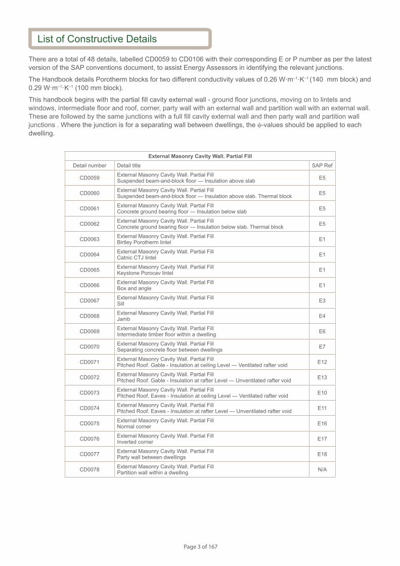
There are a total of 48 details, labelled CD0059 to CD0106 with their corresponding E or P number as per the latest version of the SAP conventions document, to assist Energy Assessors in identifying the relevant junctions.
The Handbook details Porotherm blocks for two different conductivity values of 0.26 W·m–1·K–1 (140 mm block) and 0.29 W·m–1·K–1 (100 mm block).
This handbook begins with the partial fill cavity external wall - ground floor junctions, moving on to lintels and windows, intermediate floor and roof, corner, party wall with an external wall and partition wall with an external wall. These are followed by the same junctions with a full fill cavity external wall and then party wall and partition wall junctions . Where the junction is for a separating wall between dwellings, the c-values should be applied to each dwelling.
External Masonry Cavity Wall. Partial FillDetail number Detail title SAP Ref
CD0059 External Masonry Cavity Wall. Partial Fill Suspended beam-and-block floor — Insulation above slab E5
CD0060 External Masonry Cavity Wall. Partial Fill Suspended beam-and-block floor — Insulation above slab. Thermal block E5
CD0061 External Masonry Cavity Wall. Partial Fill Concrete ground bearing floor — Insulation below slab E5
CD0062 External Masonry Cavity Wall. Partial Fill Concrete ground bearing floor — Insulation below slab. Thermal block E5
CD0063 External Masonry Cavity Wall. Partial Fill Birtley Porotherm lintel E1
CD0064 External Masonry Cavity Wall. Partial Fill Catnic CTJ lintel E1
CD0065 External Masonry Cavity Wall. Partial Fill Keystone Porocav lintel E1
CD0066 External Masonry Cavity Wall. Partial Fill Box and angle E1
CD0067 External Masonry Cavity Wall. Partial Fill Sill E3
CD0068 External Masonry Cavity Wall. Partial Fill Jamb E4
CD0069 External Masonry Cavity Wall. Partial Fill Intermediate timber floor within a dwelling E6
CD0070 External Masonry Cavity Wall. Partial Fill Separating concrete floor between dwellings E7
CD0071 External Masonry Cavity Wall. Partial Fill Pitched Roof. Gable - Insulation at ceiling Level — Ventilated rafter void E12
CD0072 External Masonry Cavity Wall. Partial Fill Pitched Roof. Gable - Insulation at rafter Level — Unventilated rafter void E13
CD0073 External Masonry Cavity Wall. Partial Fill Pitched Roof. Eaves - Insulation at ceiling Level — Ventilated rafter void E10
CD0074 External Masonry Cavity Wall. Partial Fill Pitched Roof. Eaves - Insulation at rafter Level — Unventilated rafter void E11
CD0075 External Masonry Cavity Wall. Partial Fill Normal corner E16
CD0076 External Masonry Cavity Wall. Partial Fill Inverted corner E17
CD0077 External Masonry Cavity Wall. Partial Fill Party wall between dwellings E18
CD0078 External Masonry Cavity Wall. Partial Fill Partition wall within a dwelling N/A
List of Constructive Details
Page 4 of 167
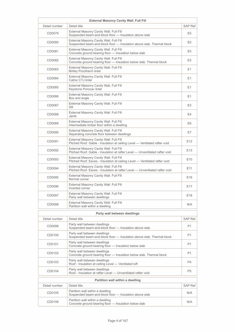
External Masonry Cavity Wall. Full FillDetail number Detail title SAP Ref
CD0079 External Masonry Cavity Wall. Full Fill Suspended beam-and-block floor — Insulation above slab E5
CD0080 External Masonry Cavity Wall. Full Fill Suspended beam-and-block floor — Insulation above slab. Thermal block E5
CD0081 External Masonry Cavity Wall. Full Fill Concrete ground bearing floor — Insulation below slab E5
CD0082 External Masonry Cavity Wall. Full Fill Concrete ground bearing floor — Insulation below slab. Thermal block E5
CD0083 External Masonry Cavity Wall. Full Fill Birtley Porotherm lintel E1
CD0084 External Masonry Cavity Wall. Full Fill Catnic CTJ lintel E1
CD0085 External Masonry Cavity Wall. Full Fill Keystone Porocav lintel E1
CD0086 External Masonry Cavity Wall. Full Fill Box and angle E1
CD0087 External Masonry Cavity Wall. Full Fill Sill E3
CD0088 External Masonry Cavity Wall. Full Fill Jamb E4
CD0089 External Masonry Cavity Wall. Full Fill Intermediate timber floor within a dwelling E6
CD0090 External Masonry Cavity Wall. Full Fill Separating concrete floor between dwellings E7
CD0091 External Masonry Cavity Wall. Full Fill Pitched Roof. Gable - Insulation at ceiling Level — Ventilated rafter void E12
CD0092 External Masonry Cavity Wall. Full Fill Pitched Roof. Gable - Insulation at rafter Level — Unventilated rafter void E13
CD0093 External Masonry Cavity Wall. Full Fill Pitched Roof. Eaves - Insulation at ceiling Level — Ventilated rafter void E10
CD0094 External Masonry Cavity Wall. Full Fill Pitched Roof. Eaves - Insulation at rafter Level — Unventilated rafter void E11
CD0095 External Masonry Cavity Wall. Full Fill Normal corner E16
CD0096 External Masonry Cavity Wall. Full Fill Inverted corner E17
CD0097 External Masonry Cavity Wall. Full Fill Party wall between dwellings E18
CD0098 External Masonry Cavity Wall. Full Fill Partition wall within a dwelling N/A
Party wall between dwellingsDetail number Detail title SAP Ref
CD0099 Party wall between dwellings Suspended beam-and-block floor — Insulation above slab P1
CD0100 Party wall between dwellings Suspended beam-and-block floor — Insulation above slab. Thermal block P1
CD0101 Party wall between dwellings Concrete ground bearing floor — Insulation below slab P1
CD0102 Party wall between dwellings Concrete ground bearing floor — Insulation below slab. Thermal block P1
CD0103 Party wall between dwellings Roof - Insulation at ceiling Level — Ventilated loft P4
CD0104 Party wall between dwellings Roof - Insulation at rafter Level — Unventilated rafter void P5
Partition wall within a dwellingDetail number Detail title SAP Ref
CD0105 Partition wall within a dwelling Suspended beam-and-block floor — Insulation above slab N/A
CD0106 Partition wall within a dwelling Concrete ground bearing floor — Insulation below slab N/A
Page 5 of 167
The details have been prepared taking into consideration the range of U values appropriate to achieve compliance within The Building Regulations 2013 (England and Wales), Part L. Therefore all of the building elements have an upper U value limit of 0.30 W·m–2·K–1 for a wall, 0.25 W·m–2·K–1 for a floor and 0.20 W·m–2·K–1 for the roof element, inline with the limiting fabric parameters given in Approved Document L2A.
The c-values are provided for different bands of U values. For each band the c-value is calculated for the worst case after considering the effect of thickness and conductivity of insulation independently. This c-value can therefore be taken for the complete range of U values quoted.
In all of the details the wall finish drawn is plasterboard on dabs. This was chosen for consistency and also as it is a common construction method. It is not, however, essential to use this internal finish solution to achieve the stated c-value. The same applies for the use of rendered block or brick for the outer leaf. Additionally the mortar joints are indicative and may not necessarily coincide with those shown in the diagrams. The maximum external wall cavity width is 200 mm and the c-values have been calculated for the 100 mm and 140 mm thick Porotherm blocks. It is also noted that care must be taken with regards to the Regulatory requirements relating to the combustibility of the insulation and the need to use fire stops, where applicable.
As a general rule, unless a specific solution for a wall or floor finish is either indicated in the Notes section or is explicitly mentioned in the annotations, it should be considered optional. The main driver in selecting the materials for each detail would be to achieve the U value bands as provided in each detail.
Some basic guidance on how to achieve air tightness is also provided. As a general rule, acceptable air barrier options to the inner face of the Porotherm block are wet plaster or Ecoparge, prior to the application of plasterboard on dabs. Where plasterboard on dabs is used, a continuous ribbon of adhesive should also be applied around all openings, along the top and bottom of the wall and at internal and external corners. In general, all penetrations through the air barrier should be sealed with a flexible sealant. This type of guidance can also be found in the current Accredited Construction Details, available at the DCLG portal. A series of tips on interpreting the information in each Constructive Detail, is given below, starting from the first to the last page.
The drawingThe front page drawing is in full colour, and the annotations identify the critical parameters that must be observed in order for this junction to achieve the calculated c-values. The annotations are also consistent with the wording used in the Notes section, to make it easier to read and understand the important elements.
The Notes This section relates to the steps in the build process of the junction that are essential for the construction of the detail with regards to achieving the stated c-values. Any other guidance by all relevant Building Regulations must be followed and this detail focuses only on the thermal performance and provides basic guidance with regards to air tightness.
The drawing The second drawing provides additional information to that given on the front page. It indicates the position of the air barrier (Ecoparge coating or wet plaster) that must be maintained and provides the necessary information to enable the U value calculation to be carried out.
c-values A table of c-values (psi-values) and temperature factors is provided for each detail. The banding of U values provides the specifier with the flexibility to use different U values for the main elements, but ensures that the calculated c-value is still valid within that range. The c-values were calculated and checked by an experienced individual, as required by Approved Document L1A, using the THERM or TRISCO software, the latter where 3D modelling was required.
The temperature factor is a property of the construction and is used to assess the risk of surface condensation or
How to use this handbook
Front page — Illustration
Main body — c-values
Page 6 of 167
mould growth. This parameter is provided in all the junctions. Depending on this value, the BRE Information Paper IP 1/06 Assessing the effects of thermal bridging at junctions and around openings, limits the risk of surface condensation or mould growth.
All c-values have been calculated in accordance with BRE Report 497 : 2007 Conventions for calculating linear thermal transmittance and temperature factors and other relevant standards quoted within that document.
U value examplesSome indicative guidance on the insulation thickness and thermal conductivity values required to achieve the U value example constructions in combination with the Porotherm blocks, are also provided. Depending on the complexity of the detail, there are one or more U value bands available. There is no specification for the type of insulation used, but the necessary information is provided to enable the calculations to be repeated. The U values were calculated in accordance with BRE Report (BR 443 : 2006) Conventions for U-value calculations and other relevant British Standards.
A fully detailed U value calculation using the stated thickness and thermal conductivity values may produce lower U values than that indicated in the details, as only the minimum amount of information is provided, such as the use of Porotherm blocks, thickness and conductivity of insulation. Other combinations of thicknesses and conductivities can be used to achieve the U values, and as long as these are within the bands provided, the corresponding c-value will still be valid. This provides the user with considerable flexibility compared to more traditional representations of c-values, while maintaining the accuracy and technical rigour of the calculation.
Guidance checklistThis part of the detail relates to the quality assurance aspect, which used in combination with guidance given on the first page, would provide reassurance to the builder that this detail will perform as expected. The creation of the list is a combination of the thermal modelling analysis of the detail and site experience.
The Notes box is intended for the inspector or the site supervisor to record any additional information or changes that may have occurred to the final built detail. It can be used as a log of the work done for each detail and as a process for checking by the site supervisor, to ensure the detail was constructed as detailed and so that the calculated c-values can be achieved.
Lets assume that you are using this junction detail where the wall consists of 100 mm Porotherm blocks (l = 0.29 W·m–1·K–1) and 50 mm of foil-faced insulation with a l value of 0.022 W·m–1·K–1. If using the example construction provided, the U value of the wall will be 0.30 W·m–2·K–1, or less, which means that the corresponding c-values would be the ones given in the second line and first column of the table, so either 0.095 W·m–1·K–1, 0.096 W·m–1·K–1 or 0.090 W·m–1·K–1.
Now you need to decide on the U value of the floor. This U value will be dependent on its exposed perimeter length to area ratio (P/A), so for example if the U value is 0.22 W·m–2·K–1 for a P/A ratio of 0.50, then the corresponding U value for a P/A ratio of 0.25 would be between 0.12 and 0.19 W·m–2·K–1 (Case 2). In this case, the c-value for this detail would be 0.096 W·m–1·K–1. Following the examples provided for the floor U value, this floor U value could be achieved using between 60 mm and 120 mm of insulation with a l value of 0.023 W·m–1·K–1.
If the U value you chose was 0.22 W·m–2·K–1 but for a ratio of 0.35, then the corresponding floor U value for the floor at P/A = 0.25 would be higher then 0.20 W·m–2·K–1, which means that the c-value for this detail would be 0.090 W·m–1·K–1.
In summary, for the ground floor details, the P/A ratio tables provide the user with additional flexibility to calculate the corresponding floor U values, without having to perform each calculation separately.
Please refer to www.constructivedetails.co.uk for full terms and conditions.
You may not edit or amend the contents or format or otherwise incorporate them into any other publication or work or media.
Terms and conditions
Example using CD0059
Last page — Checklist
Page 7 of 167
S154083_CD1-1
Beam and Block Floor. Insulation Above Slab.
Notes
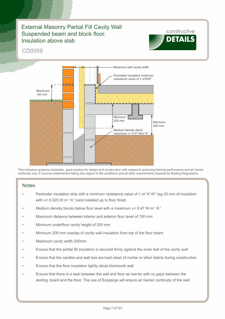
• Perimeter insulation strip with a minimum resistance value of 1 m2·K·W-1 (eg 25 mm of insulation with l= 0.025 W·m-1·K-1) and installed up to floor finish
• Medium density blocks below floor level with a maximum l= 0.47 W·m-1·K-1
• Maximum distance between interior and exterior floor level of 150 mm
• Minimum underfloor cavity height of 200 mm
• Minimum 200 mm overlap of cavity wall insulation from top of the floor beam
• Maximum cavity width 200mm
• Ensure that the partial fill insulation is secured firmly against the inner leaf of the cavity wall
• Ensure that the cavities and wall ties are kept clean of mortar or other debris during construction
• Ensure that the floor insulation tightly abuts blockwork wall
• Ensure that there is a seal between the wall and floor air barrier with no gaps between the skirting board and the floor. The use of Ecoparge will ensure air barrier continuity of the wall.
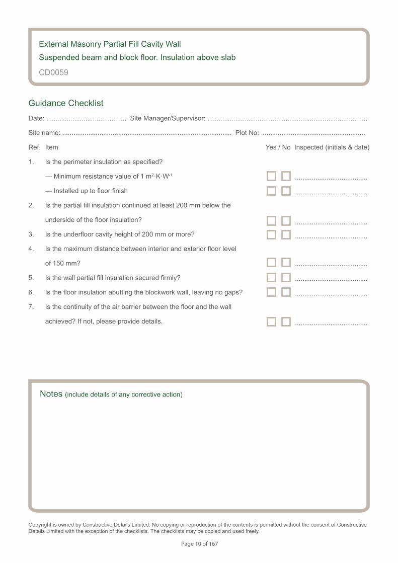
External Masonry Partial Fill Cavity WallSuspended beam and block floor. Insulation above slab
CD0059
This indicative guidance illustrates good practice for design and construction with respect to achieving thermal performance and air barrier continuity only. It must be implemented taking due regard of site conditions and all other requirements imposed by Buiding Regulations.
Maximum wall cavity width
Minimum 200 mm
Maximum 150 mm
Minimum 200 mm
Medium density block maximum l= 0.47 Wm-1K-1
Perimeter insulation minimum resistance value of 1 m2KW-1
Page 8 of 167
S154083_CD1-2
Beam and Block Floor. Insulation Above Slab.
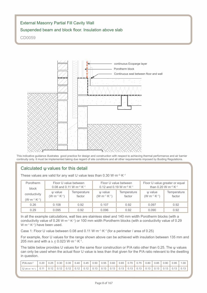
Calculated ψ values for this detailThese values are valid for any wall U value less than 0.30 W·m–2·K–1
Porotherm
block
conductivity
(W·m–1·K–1)
Floor U value between 0.08 and 0.11 W·m–2·K–1
Floor U value between 0.12 and 0.19 W·m–2·K–1
Floor U value greater or equal than 0.20 W·m–2·K–1
ψ value (W·m–1·K–1)
Temperaturefactor
ψ value (W·m–1·K–1)
Temperaturefactor
ψ value (W·m–1·K–1)
Temperaturefactor
0.26 0.108 0.92 0.107 0.92 0.097 0.92
0.29 0.095 0.92 0.096 0.92 0.090 0.92
In all the example calculations, wall ties are stainless steel and 140 mm width Porotherm blocks (with a conductivity value of 0.26 W·m–1·K–1) or 100 mm width Porotherm blocks (with a conductivity value of 0.29 W·m–1·K–1) have been used.
Case 1: Floor U value between 0.08 and 0.11 W·m–1·K–1 (for a perimeter / area of 0.25)
For example, floor U values for the range shown above can be achieved with insulation between 135 mm and 205 mm and with a l < 0.023 W·m–1·K–1.
The table below provides U values for the same floor construction or P/A ratio other than 0.25. The ψ values can only be used when the actual floor U value is less than that given for the P/A ratio relevant to the dwelling in question.
P/A mm-2 0.20 0.25 0.30 0.35 0.40 0.45 0.50 0.55 0.60 0.65 0.70 0.75 0.80 0.85 0.90 0.95 1.00
U (W·m–1·K–1) 0.11 0.12 0.12 0.12 0.12 0.12 0.13 0.13 0.13 0.13 0.13 0.13 0.13 0.13 0.13 0.13 0.13
External Masonry Partial Fill Cavity Wall
Suspended beam and block floor. Insulation above slab
CD0059
This indicative guidance illustrates good practice for design and construction with respect to achieving thermal performance and air barrier continuity only. It must be implemented taking due regard of site conditions and all other requirements imposed by Buiding Regulations.
continuous Ecoparge layer
Porotherm block
Continuous seal between floor and wall
Page 9 of 167
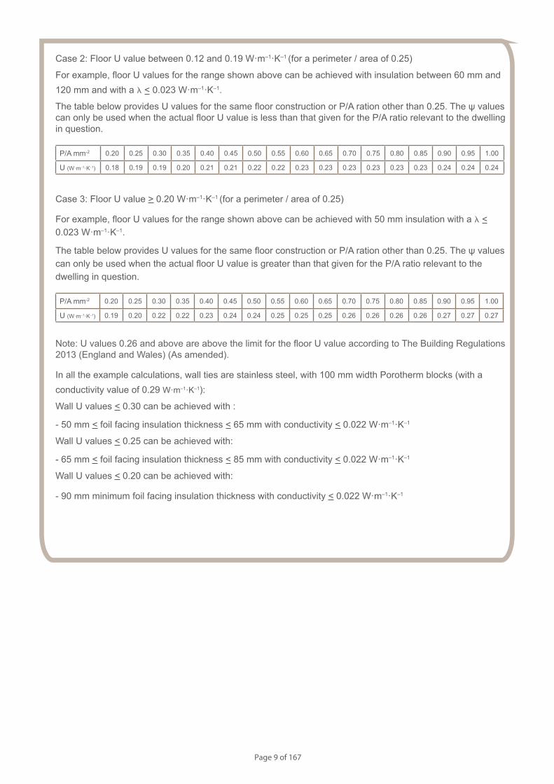
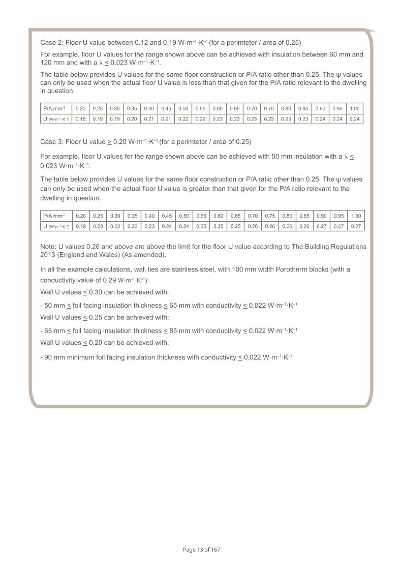
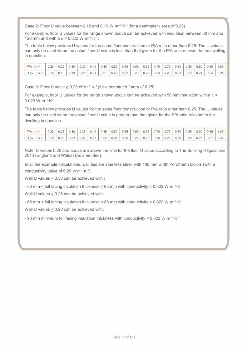
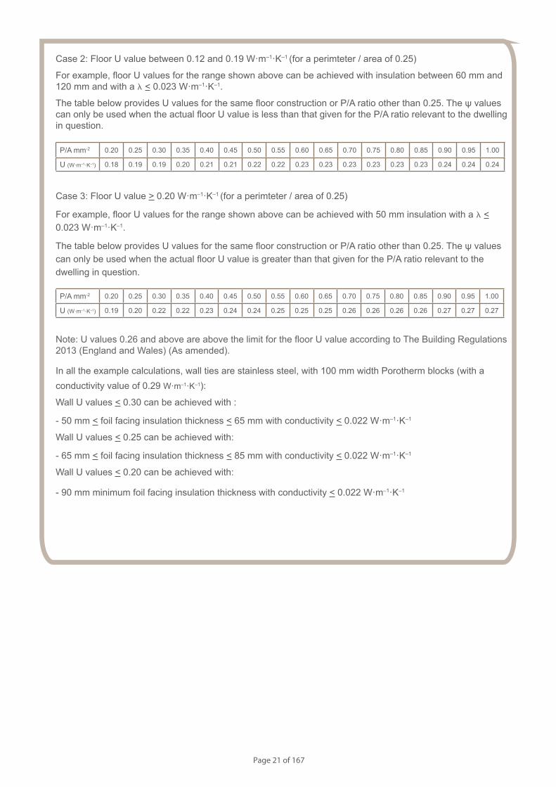
Case 2: Floor U value between 0.12 and 0.19 W·m–1·K–1 (for a perimeter / area of 0.25)
For example, floor U values for the range shown above can be achieved with insulation between 60 mm and 120 mm and with a l < 0.023 W·m–1·K–1.
The table below provides U values for the same floor construction or P/A ration other than 0.25. The ψ values can only be used when the actual floor U value is less than that given for the P/A ratio relevant to the dwelling in question.
P/A mm-2 0.20 0.25 0.30 0.35 0.40 0.45 0.50 0.55 0.60 0.65 0.70 0.75 0.80 0.85 0.90 0.95 1.00
U (W·m–1·K–1) 0.18 0.19 0.19 0.20 0.21 0.21 0.22 0.22 0.23 0.23 0.23 0.23 0.23 0.23 0.24 0.24 0.24
Case 3: Floor U value > 0.20 W·m–1·K–1 (for a perimeter / area of 0.25)
For example, floor U values for the range shown above can be achieved with 50 mm insulation with a l < 0.023 W·m–1·K–1.
The table below provides U values for the same floor construction or P/A ration other than 0.25. The ψ values can only be used when the actual floor U value is greater than that given for the P/A ratio relevant to the dwelling in question.
P/A mm-2 0.20 0.25 0.30 0.35 0.40 0.45 0.50 0.55 0.60 0.65 0.70 0.75 0.80 0.85 0.90 0.95 1.00
U (W·m–1·K–1) 0.19 0.20 0.22 0.22 0.23 0.24 0.24 0.25 0.25 0.25 0.26 0.26 0.26 0.26 0.27 0.27 0.27
Note: U values 0.26 and above are above the limit for the floor U value according to The Building Regulations 2013 (England and Wales) (As amended).
In all the example calculations, wall ties are stainless steel, with 100 mm width Porotherm blocks (with a conductivity value of 0.29 W·m–1·K–1):
Wall U values < 0.30 can be achieved with :
- 50 mm < foil facing insulation thickness < 65 mm with conductivity < 0.022 W·m–1·K–1
Wall U values < 0.25 can be achieved with:
- 65 mm < foil facing insulation thickness < 85 mm with conductivity < 0.022 W·m–1·K–1
Wall U values < 0.20 can be achieved with:
- 90 mm minimum foil facing insulation thickness with conductivity < 0.022 W·m–1·K–1
Page 10 of 167
Notes (include details of any corrective action)
CD0059
Guidance Checklist
Date: ........................................... Site Manager/Supervisor: ......................................................................................
Site name: ........................................................................................... Plot No: ........................................................
Ref. Item Yes / No Inspected (initials & date)
1. Is the perimeter insulation as specified?
— Minimum resistance value of 1 m2·K·W-1
— Installed up to floor finish
2. Is the partial fill insulation continued at least 200 mm below the
underside of the floor insulation?
3. Is the underfloor cavity height of 200 mm or more?
4. Is the maximum distance between interior and exterior floor level
of 150 mm?
5. Is the wall partial fill insulation secured firmly?
6. Is the floor insulation abutting the blockwork wall, leaving no gaps?
7. Is the continuity of the air barrier between the floor and the wall
achieved? If not, please provide details.
Copyright is owned by Constructive Details Limited. No copying or reproduction of the contents is permitted without the consent of Constructive Details Limited with the exception of the checklists. The checklists may be copied and used freely.
.......................................
.......................................
.......................................
.......................................
.......................................
.......................................
External Masonry Partial Fill Cavity Wall
Suspended beam and block floor. Insulation above slab
.......................................
.......................................
Page 11 of 167
Notes
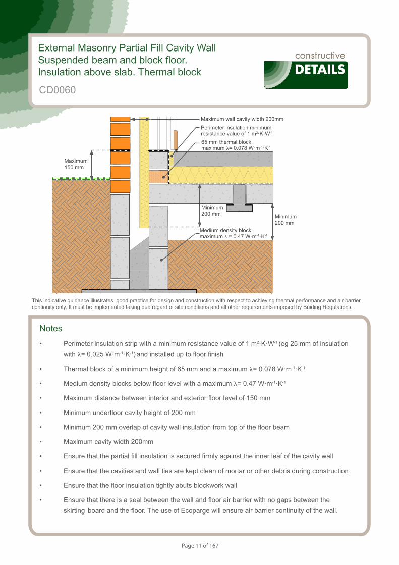
• Perimeter insulation strip with a minimum resistance value of 1 m2·K·W-1 (eg 25 mm of insulation with l= 0.025 W·m-1·K-1) and installed up to floor finish
• Thermal block of a minimum height of 65 mm and a maximum l= 0.078 W·m-1·K-1
• Medium density blocks below floor level with a maximum l= 0.47 W·m-1·K-1
• Maximum distance between interior and exterior floor level of 150 mm
• Minimum underfloor cavity height of 200 mm
• Minimum 200 mm overlap of cavity wall insulation from top of the floor beam
• Maximum cavity width 200mm
• Ensure that the partial fill insulation is secured firmly against the inner leaf of the cavity wall
• Ensure that the cavities and wall ties are kept clean of mortar or other debris during construction
• Ensure that the floor insulation tightly abuts blockwork wall
• Ensure that there is a seal between the wall and floor air barrier with no gaps between the skirting board and the floor. The use of Ecoparge will ensure air barrier continuity of the wall.
S154083_CD2-1
Beam and Block Floor. Insulation Above Slab.
External Masonry Partial Fill Cavity WallSuspended beam and block floor. Insulation above slab. Thermal block
CD0060
This indicative guidance illustrates good practice for design and construction with respect to achieving thermal performance and air barrier continuity only. It must be implemented taking due regard of site conditions and all other requirements imposed by Buiding Regulations.
Maximum wall cavity width 200mm
Minimum 200 mm
Maximum 150 mm
Minimum 200 mm
Medium density block maximum l = 0.47 W·m-1·K-1
Perimeter insulation minimum resistance value of 1 m2·K·W-1
65 mm thermal block maximum l= 0.078 W·m-1·K-1
Page 12 of 167
S154083_CD2-1
Beam and Block Floor. Insulation Above Slab.
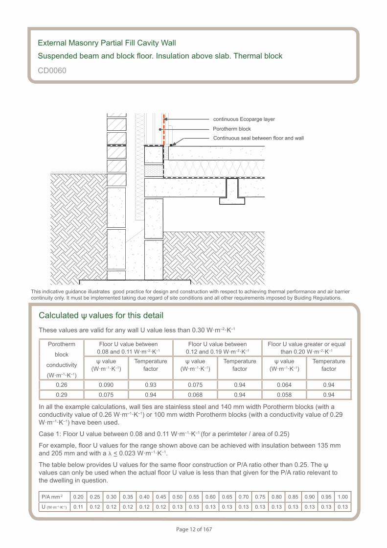
Calculated ψ values for this detail
These values are valid for any wall U value less than 0.30 W·m–2·K–1
Porotherm
block
conductivity
(W·m–1·K–1)
Floor U value between 0.08 and 0.11 W·m–2·K–1
Floor U value between 0.12 and 0.19 W·m–2·K–1
Floor U value greater or equal than 0.20 W·m–2·K–1
ψ value (W·m–1·K–1)
Temperaturefactor
ψ value (W·m–1·K–1)
Temperaturefactor
ψ value (W·m–1·K–1)
Temperaturefactor
0.26 0.090 0.93 0.075 0.94 0.064 0.94
0.29 0.075 0.94 0.068 0.94 0.058 0.94
In all the example calculations, wall ties are stainless steel and 140 mm width Porotherm blocks (with a conductivity value of 0.26 W·m–1·K–1) or 100 mm width Porotherm blocks (with a conductivity value of 0.29 W·m–1·K–1) have been used.
Case 1: Floor U value between 0.08 and 0.11 W·m–1·K–1 (for a perimteter / area of 0.25)
For example, floor U values for the range shown above can be achieved with insulation between 135 mm and 205 mm and with a l < 0.023 W·m–1·K–1.
The table below provides U values for the same floor construction or P/A ratio other than 0.25. The ψ values can only be used when the actual floor U value is less than that given for the P/A ratio relevant to the dwelling in question.
P/A mm-2 0.20 0.25 0.30 0.35 0.40 0.45 0.50 0.55 0.60 0.65 0.70 0.75 0.80 0.85 0.90 0.95 1.00
U (W·m–1·K–1) 0.11 0.12 0.12 0.12 0.12 0.12 0.13 0.13 0.13 0.13 0.13 0.13 0.13 0.13 0.13 0.13 0.13
External Masonry Partial Fill Cavity Wall
Suspended beam and block floor. Insulation above slab. Thermal block
CD0060
This indicative guidance illustrates good practice for design and construction with respect to achieving thermal performance and air barrier continuity only. It must be implemented taking due regard of site conditions and all other requirements imposed by Buiding Regulations.
continuous Ecoparge layer
Porotherm block
Continuous seal between floor and wall
Page 13 of 167
Case 2: Floor U value between 0.12 and 0.19 W·m–1·K–1 (for a perimteter / area of 0.25)
For example, floor U values for the range shown above can be achieved with insulation between 60 mm and 120 mm and with a l < 0.023 W·m–1·K–1.
The table below provides U values for the same floor construction or P/A ratio other than 0.25. The ψ values can only be used when the actual floor U value is less than that given for the P/A ratio relevant to the dwelling in question.
P/A mm-2 0.20 0.25 0.30 0.35 0.40 0.45 0.50 0.55 0.60 0.65 0.70 0.75 0.80 0.85 0.90 0.95 1.00
U (W·m–1·K–1) 0.18 0.19 0.19 0.20 0.21 0.21 0.22 0.22 0.23 0.23 0.23 0.23 0.23 0.23 0.24 0.24 0.24
Case 3: Floor U value > 0.20 W·m–1·K–1 (for a perimteter / area of 0.25)
For example, floor U values for the range shown above can be achieved with 50 mm insulation with a l < 0.023 W·m–1·K–1.
The table below provides U values for the same floor construction or P/A ratio other than 0.25. The ψ values can only be used when the actual floor U value is greater than that given for the P/A ratio relevant to the dwelling in question.
P/A mm-2 0.20 0.25 0.30 0.35 0.40 0.45 0.50 0.55 0.60 0.65 0.70 0.75 0.80 0.85 0.90 0.95 1.00
U (W·m–1·K–1) 0.19 0.20 0.22 0.22 0.23 0.24 0.24 0.25 0.25 0.25 0.26 0.26 0.26 0.26 0.27 0.27 0.27
Note: U values 0.26 and above are above the limit for the floor U value according to The Building Regulations 2013 (England and Wales) (As amended).
In all the example calculations, wall ties are stainless steel, with 100 mm width Porotherm blocks (with a conductivity value of 0.29 W·m–1·K–1):
Wall U values < 0.30 can be achieved with :
- 50 mm < foil facing insulation thickness < 65 mm with conductivity < 0.022 W·m–1·K–1
Wall U values < 0.25 can be achieved with:
- 65 mm < foil facing insulation thickness < 85 mm with conductivity < 0.022 W·m–1·K–1
Wall U values < 0.20 can be achieved with:
- 90 mm minimum foil facing insulation thickness with conductivity < 0.022 W·m–1·K–1
Page 14 of 167
Notes (include details of any corrective action)
CD0060
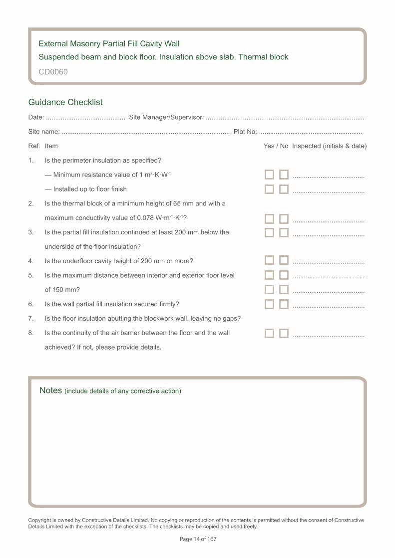
Guidance Checklist
Date: ........................................... Site Manager/Supervisor: ......................................................................................
Site name: ........................................................................................... Plot No: ........................................................
Ref. Item Yes / No Inspected (initials & date)
1. Is the perimeter insulation as specified?
— Minimum resistance value of 1 m2·K·W-1
— Installed up to floor finish
2. Is the thermal block of a minimum height of 65 mm and with a
maximum conductivity value of 0.078 W·m-1·K-1?
3. Is the partial fill insulation continued at least 200 mm below the
underside of the floor insulation?
4. Is the underfloor cavity height of 200 mm or more?
5. Is the maximum distance between interior and exterior floor level
of 150 mm?
6. Is the wall partial fill insulation secured firmly?
7. Is the floor insulation abutting the blockwork wall, leaving no gaps?
8. Is the continuity of the air barrier between the floor and the wall
achieved? If not, please provide details.
Copyright is owned by Constructive Details Limited. No copying or reproduction of the contents is permitted without the consent of Constructive Details Limited with the exception of the checklists. The checklists may be copied and used freely.
.......................................
.......................................
.......................................
.......................................
.......................................
.......................................
.......................................
.......................................
.......................................
External Masonry Partial Fill Cavity Wall
Suspended beam and block floor. Insulation above slab. Thermal block
Page 15 of 167
Notes
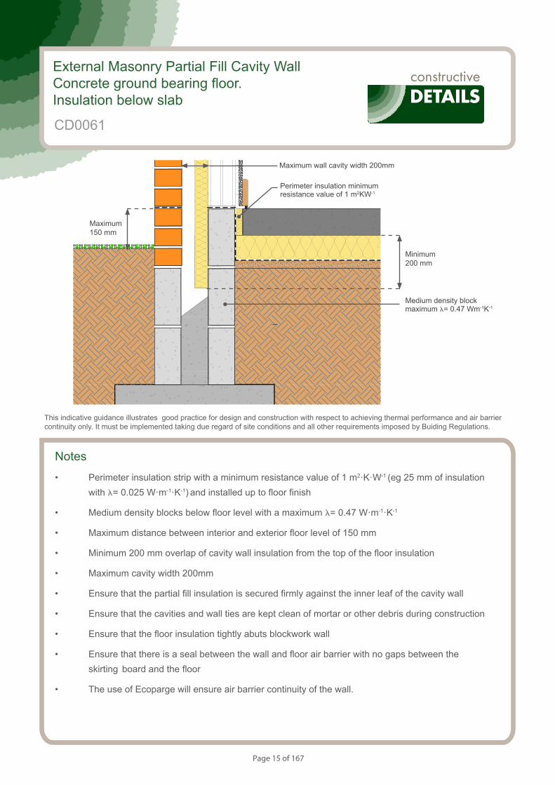
• Perimeter insulation strip with a minimum resistance value of 1 m2·K·W-1 (eg 25 mm of insulation with l= 0.025 W·m-1·K-1) and installed up to floor finish
• Medium density blocks below floor level with a maximum l= 0.47 W·m-1·K-1
• Maximum distance between interior and exterior floor level of 150 mm
• Minimum 200 mm overlap of cavity wall insulation from the top of the floor insulation
• Maximum cavity width 200mm
• Ensure that the partial fill insulation is secured firmly against the inner leaf of the cavity wall
• Ensure that the cavities and wall ties are kept clean of mortar or other debris during construction
• Ensure that the floor insulation tightly abuts blockwork wall
• Ensure that there is a seal between the wall and floor air barrier with no gaps between the skirting board and the floor
• The use of Ecoparge will ensure air barrier continuity of the wall.
S154083_CD3-1
Concrete Ground Bearing Floor. Insulation Below Slab.
External Masonry Partial Fill Cavity WallConcrete ground bearing floor. Insulation below slab
CD0061
This indicative guidance illustrates good practice for design and construction with respect to achieving thermal performance and air barrier continuity only. It must be implemented taking due regard of site conditions and all other requirements imposed by Buiding Regulations.
Maximum wall cavity width 200mm
Minimum 200 mm
Maximum 150 mm
Medium density block maximum l= 0.47 Wm-1K-1
Perimeter insulation minimum resistance value of 1 m2KW-1
Page 16 of 167
S154083_CD3-2
Concrete Ground Bearing Floor. Insulation Below Slab.
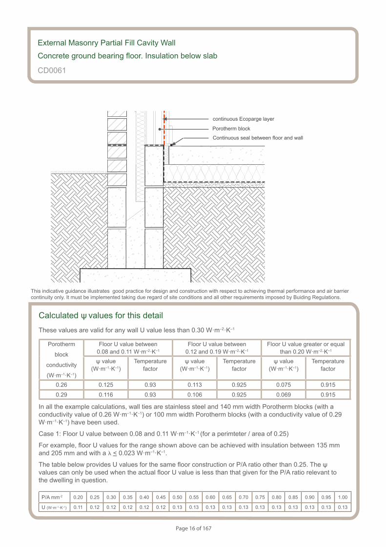
Calculated ψ values for this detail
These values are valid for any wall U value less than 0.30 W·m–2·K–1
Porotherm
block
conductivity
(W·m–1·K–1)
Floor U value between 0.08 and 0.11 W·m–2·K–1
Floor U value between 0.12 and 0.19 W·m–2·K–1
Floor U value greater or equal than 0.20 W·m–2·K–1
ψ value (W·m–1·K–1)
Temperaturefactor
ψ value (W·m–1·K–1)
Temperaturefactor
ψ value (W·m–1·K–1)
Temperaturefactor
0.26 0.125 0.93 0.113 0.925 0.075 0.915
0.29 0.116 0.93 0.106 0.925 0.069 0.915
In all the example calculations, wall ties are stainless steel and 140 mm width Porotherm blocks (with a conductivity value of 0.26 W·m–1·K–1) or 100 mm width Porotherm blocks (with a conductivity value of 0.29 W·m–1·K–1) have been used.
Case 1: Floor U value between 0.08 and 0.11 W·m–1·K–1 (for a perimteter / area of 0.25)
For example, floor U values for the range shown above can be achieved with insulation between 135 mm and 205 mm and with a l < 0.023 W·m–1·K–1.
The table below provides U values for the same floor construction or P/A ratio other than 0.25. The ψ values can only be used when the actual floor U value is less than that given for the P/A ratio relevant to the dwelling in question.
P/A mm-2 0.20 0.25 0.30 0.35 0.40 0.45 0.50 0.55 0.60 0.65 0.70 0.75 0.80 0.85 0.90 0.95 1.00
U (W·m–1·K–1) 0.11 0.12 0.12 0.12 0.12 0.12 0.13 0.13 0.13 0.13 0.13 0.13 0.13 0.13 0.13 0.13 0.13
External Masonry Partial Fill Cavity Wall
Concrete ground bearing floor. Insulation below slab
CD0061
This indicative guidance illustrates good practice for design and construction with respect to achieving thermal performance and air barrier continuity only. It must be implemented taking due regard of site conditions and all other requirements imposed by Buiding Regulations.
continuous Ecoparge layer
Porotherm block
Continuous seal between floor and wall
Page 17 of 167
Case 2: Floor U value between 0.12 and 0.19 W·m–1·K–1 (for a perimteter / area of 0.25)
For example, floor U values for the range shown above can be achieved with insulation between 60 mm and 120 mm and with a l < 0.023 W·m–1·K–1.
The table below provides U values for the same floor construction or P/A ratio other than 0.25. The ψ values can only be used when the actual floor U value is less than that given for the P/A ratio relevant to the dwelling in question.
P/A mm-2 0.20 0.25 0.30 0.35 0.40 0.45 0.50 0.55 0.60 0.65 0.70 0.75 0.80 0.85 0.90 0.95 1.00
U (W·m–1·K–1) 0.18 0.19 0.19 0.20 0.21 0.21 0.22 0.22 0.23 0.23 0.23 0.23 0.23 0.23 0.24 0.24 0.24
Case 3: Floor U value > 0.20 W·m–1·K–1 (for a perimteter / area of 0.25)
For example, floor U values for the range shown above can be achieved with 50 mm insulation with a l < 0.023 W·m–1·K–1.
The table below provides U values for the same floor construction or P/A ratio other than 0.25. The ψ values can only be used when the actual floor U value is greater than that given for the P/A ratio relevant to the dwelling in question.
P/A mm-2 0.20 0.25 0.30 0.35 0.40 0.45 0.50 0.55 0.60 0.65 0.70 0.75 0.80 0.85 0.90 0.95 1.00
U (W·m–1·K–1) 0.19 0.20 0.22 0.22 0.23 0.24 0.24 0.25 0.25 0.25 0.26 0.26 0.26 0.26 0.27 0.27 0.27
Note: U values 0.26 and above are above the limit for the floor U value according to The Building Regulations 2013 (England and Wales) (As amended).
In all the example calculations, wall ties are stainless steel, with 100 mm width Porotherm blocks (with a conductivity value of 0.29 W·m–1·K–1):
Wall U values < 0.30 can be achieved with :
- 50 mm < foil facing insulation thickness < 65 mm with conductivity < 0.022 W·m–1·K–1
Wall U values < 0.25 can be achieved with:
- 65 mm < foil facing insulation thickness < 85 mm with conductivity < 0.022 W·m–1·K–1
Wall U values < 0.20 can be achieved with:
- 90 mm minimum foil facing insulation thickness with conductivity < 0.022 W·m–1·K–1
Page 18 of 167
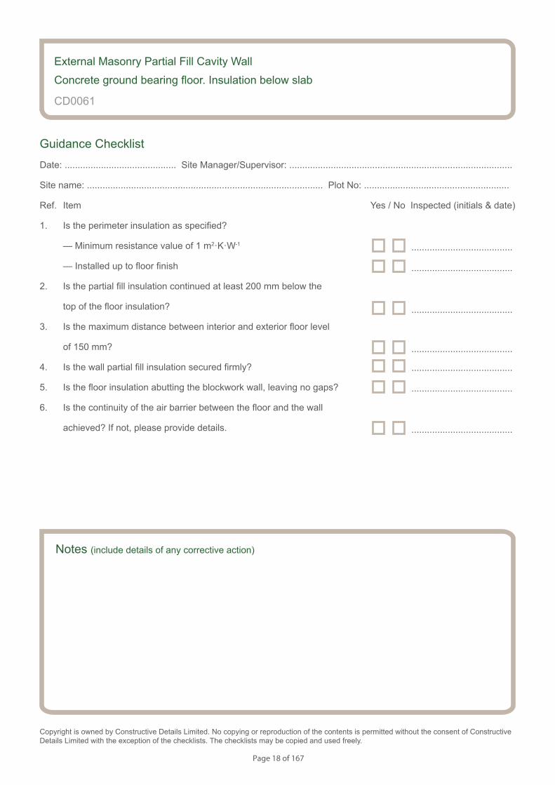
Notes (include details of any corrective action)
CD0061
Guidance Checklist
Date: ........................................... Site Manager/Supervisor: ......................................................................................
Site name: ........................................................................................... Plot No: ........................................................
Ref. Item Yes / No Inspected (initials & date)
1. Is the perimeter insulation as specified?
— Minimum resistance value of 1 m2·K·W-1
— Installed up to floor finish
2. Is the partial fill insulation continued at least 200 mm below the
top of the floor insulation?
3. Is the maximum distance between interior and exterior floor level
of 150 mm?
4. Is the wall partial fill insulation secured firmly?
5. Is the floor insulation abutting the blockwork wall, leaving no gaps?
6. Is the continuity of the air barrier between the floor and the wall
achieved? If not, please provide details.
Copyright is owned by Constructive Details Limited. No copying or reproduction of the contents is permitted without the consent of Constructive Details Limited with the exception of the checklists. The checklists may be copied and used freely.
.......................................
.......................................
.......................................
.......................................
.......................................
.......................................
.......................................
External Masonry Partial Fill Cavity Wall
Concrete ground bearing floor. Insulation below slab
Page 19 of 167
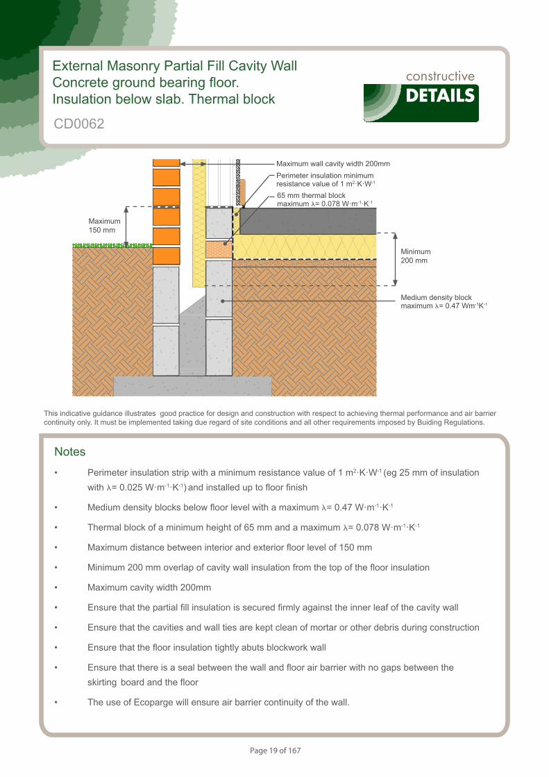
Notes
• Perimeter insulation strip with a minimum resistance value of 1 m2·K·W-1 (eg 25 mm of insulation with l= 0.025 W·m-1·K-1) and installed up to floor finish
• Medium density blocks below floor level with a maximum l= 0.47 W·m-1·K-1
• Thermal block of a minimum height of 65 mm and a maximum l= 0.078 W·m-1·K-1
• Maximum distance between interior and exterior floor level of 150 mm
• Minimum 200 mm overlap of cavity wall insulation from the top of the floor insulation
• Maximum cavity width 200mm
• Ensure that the partial fill insulation is secured firmly against the inner leaf of the cavity wall
• Ensure that the cavities and wall ties are kept clean of mortar or other debris during construction
• Ensure that the floor insulation tightly abuts blockwork wall
• Ensure that there is a seal between the wall and floor air barrier with no gaps between the skirting board and the floor
• The use of Ecoparge will ensure air barrier continuity of the wall.
S154083_CD4-1
Concrete Ground Bearing Floor. Insulation Below Slab.Thermal block
External Masonry Partial Fill Cavity WallConcrete ground bearing floor. Insulation below slab. Thermal block
CD0062
This indicative guidance illustrates good practice for design and construction with respect to achieving thermal performance and air barrier continuity only. It must be implemented taking due regard of site conditions and all other requirements imposed by Buiding Regulations.
Minimum 200 mm
Maximum 150 mm
Medium density block maximum l= 0.47 Wm-1K-1
Maximum wall cavity width 200mmPerimeter insulation minimum resistance value of 1 m2·K·W-1
65 mm thermal block maximum l= 0.078 W·m-1·K-1
Page 20 of 167
S154083_CD4-2
Concrete Ground Bearing Floor. Insulation Below Slab.Thermal block
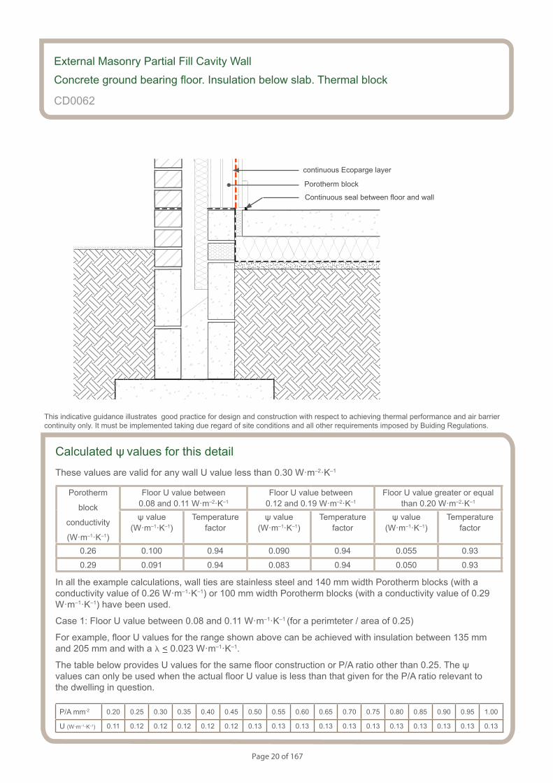
Calculated ψ values for this detail
These values are valid for any wall U value less than 0.30 W·m–2·K–1
Porotherm
block
conductivity
(W·m–1·K–1)
Floor U value between 0.08 and 0.11 W·m–2·K–1
Floor U value between 0.12 and 0.19 W·m–2·K–1
Floor U value greater or equal than 0.20 W·m–2·K–1
ψ value (W·m–1·K–1)
Temperaturefactor
ψ value (W·m–1·K–1)
Temperaturefactor
ψ value (W·m–1·K–1)
Temperaturefactor
0.26 0.100 0.94 0.090 0.94 0.055 0.93
0.29 0.091 0.94 0.083 0.94 0.050 0.93
In all the example calculations, wall ties are stainless steel and 140 mm width Porotherm blocks (with a conductivity value of 0.26 W·m–1·K–1) or 100 mm width Porotherm blocks (with a conductivity value of 0.29 W·m–1·K–1) have been used.
Case 1: Floor U value between 0.08 and 0.11 W·m–1·K–1 (for a perimteter / area of 0.25)
For example, floor U values for the range shown above can be achieved with insulation between 135 mm and 205 mm and with a l < 0.023 W·m–1·K–1.
The table below provides U values for the same floor construction or P/A ratio other than 0.25. The ψ values can only be used when the actual floor U value is less than that given for the P/A ratio relevant to the dwelling in question.
P/A mm-2 0.20 0.25 0.30 0.35 0.40 0.45 0.50 0.55 0.60 0.65 0.70 0.75 0.80 0.85 0.90 0.95 1.00
U (W·m–1·K–1) 0.11 0.12 0.12 0.12 0.12 0.12 0.13 0.13 0.13 0.13 0.13 0.13 0.13 0.13 0.13 0.13 0.13
External Masonry Partial Fill Cavity Wall
Concrete ground bearing floor. Insulation below slab. Thermal block
CD0062
This indicative guidance illustrates good practice for design and construction with respect to achieving thermal performance and air barrier continuity only. It must be implemented taking due regard of site conditions and all other requirements imposed by Buiding Regulations.
continuous Ecoparge layer
Porotherm block
Continuous seal between floor and wall
Page 21 of 167
Case 2: Floor U value between 0.12 and 0.19 W·m–1·K–1 (for a perimteter / area of 0.25)
For example, floor U values for the range shown above can be achieved with insulation between 60 mm and 120 mm and with a l < 0.023 W·m–1·K–1.
The table below provides U values for the same floor construction or P/A ratio other than 0.25. The ψ values can only be used when the actual floor U value is less than that given for the P/A ratio relevant to the dwelling in question.
P/A mm-2 0.20 0.25 0.30 0.35 0.40 0.45 0.50 0.55 0.60 0.65 0.70 0.75 0.80 0.85 0.90 0.95 1.00
U (W·m–1·K–1) 0.18 0.19 0.19 0.20 0.21 0.21 0.22 0.22 0.23 0.23 0.23 0.23 0.23 0.23 0.24 0.24 0.24
Case 3: Floor U value > 0.20 W·m–1·K–1 (for a perimteter / area of 0.25)
For example, floor U values for the range shown above can be achieved with 50 mm insulation with a l < 0.023 W·m–1·K–1.
The table below provides U values for the same floor construction or P/A ratio other than 0.25. The ψ values can only be used when the actual floor U value is greater than that given for the P/A ratio relevant to the dwelling in question.
P/A mm-2 0.20 0.25 0.30 0.35 0.40 0.45 0.50 0.55 0.60 0.65 0.70 0.75 0.80 0.85 0.90 0.95 1.00
U (W·m–1·K–1) 0.19 0.20 0.22 0.22 0.23 0.24 0.24 0.25 0.25 0.25 0.26 0.26 0.26 0.26 0.27 0.27 0.27
Note: U values 0.26 and above are above the limit for the floor U value according to The Building Regulations 2013 (England and Wales) (As amended).
In all the example calculations, wall ties are stainless steel, with 100 mm width Porotherm blocks (with a conductivity value of 0.29 W·m–1·K–1):
Wall U values < 0.30 can be achieved with :
- 50 mm < foil facing insulation thickness < 65 mm with conductivity < 0.022 W·m–1·K–1
Wall U values < 0.25 can be achieved with:
- 65 mm < foil facing insulation thickness < 85 mm with conductivity < 0.022 W·m–1·K–1
Wall U values < 0.20 can be achieved with:
- 90 mm minimum foil facing insulation thickness with conductivity < 0.022 W·m–1·K–1

Page 22 of 167
Notes (include details of any corrective action)
CD0062
Guidance Checklist
Date: ........................................... Site Manager/Supervisor: ......................................................................................
Site name: ........................................................................................... Plot No: ........................................................
Ref. Item Yes / No Inspected (initials & date)
1. Is the perimeter insulation as specified?
— Minimum resistance value of 1 m2·K·W-1
— Installed up to floor finish
2. Is the thermal block of a minimum height of 65 mm and with a
maximum conductivity value of 0.078 W·m-1·K-1?
3. Is the partial fill insulation continued at least 200 mm below the
top of the floor insulation?
4. Is the maximum distance between interior and exterior floor level
of 150 mm?
5. Is the wall partial fill insulation secured firmly?
6. Is the floor insulation abutting the blockwork wall, leaving no gaps?
7. Is the continuity of the air barrier between the floor and the wall
achieved? If not, please provide details.
Copyright is owned by Constructive Details Limited. No copying or reproduction of the contents is permitted without the consent of Constructive Details Limited with the exception of the checklists. The checklists may be copied and used freely.
.......................................
.......................................
.......................................
.......................................
.......................................
.......................................
.......................................
.......................................
External Masonry Partial Fill Cavity Wall
Concrete ground bearing floor. Insulation below slab. Thermal block

Page 23 of 167
S154083_CD5-1
Birtley lintel
Notes
• Minimum frame overlap of 30mm
• Cavity width between 90 and 165 mm (range covered by Birtley lintels)
• Ensure continuity of the insulation throughout the junction leaving no gaps
• Ensure that the partial fill wall insulation is secured firmly against the inner leaf of the cavity wall
• Ensure cavities and wall ties are kept clean of mortar or other debris during construction
• Flexible sealant should be applied to the junction of the plasterboard and the window frame
• the use of Ecoparge will ensure air barrier continuity
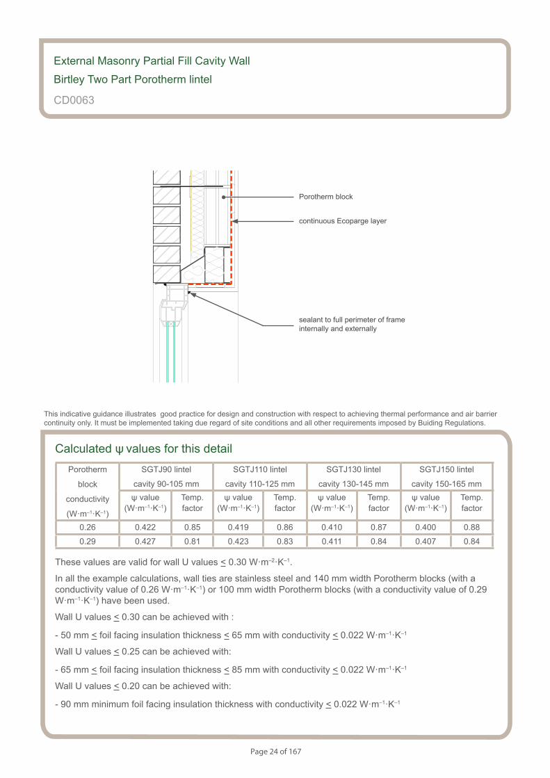
External Masonry Partial Fill Cavity Wall
Birtley Two Part Porotherm lintel
CD0063
This indicative guidance illustrates good practice for design and construction with respect to achieving thermal performance and air barrier continuity only. It must be implemented taking due regard of site conditions and all other requirements imposed by Buiding Regulations.
minimum frame overlap 30 mm
cavity width 90-165 mm
insulation inside lintel maximum l=0.038 W·m-1·K-1
Page 24 of 167
S154083_CD5-2
Birtley lintel
External Masonry Partial Fill Cavity Wall
Birtley Two Part Porotherm lintel
CD0063
sealant to full perimeter of frame internally and externally
This indicative guidance illustrates good practice for design and construction with respect to achieving thermal performance and air barrier continuity only. It must be implemented taking due regard of site conditions and all other requirements imposed by Buiding Regulations.
continuous Ecoparge layer
Porotherm block
Calculated ψ values for this detailPorotherm
block
conductivity
(W·m–1·K–1)
SGTJ90 lintel
cavity 90-105 mm
SGTJ110 lintel
cavity 110-125 mm
SGTJ130 lintel
cavity 130-145 mm
SGTJ150 lintel
cavity 150-165 mmψ value
(W·m–1·K–1)Temp.factor
ψ value (W·m–1·K–1)
Temp.factor
ψ value (W·m–1·K–1)
Temp.factor
ψ value (W·m–1·K–1)
Temp.factor
0.26 0.422 0.85 0.419 0.86 0.410 0.87 0.400 0.88
0.29 0.427 0.81 0.423 0.83 0.411 0.84 0.407 0.84
These values are valid for wall U values < 0.30 W·m–2·K–1.
In all the example calculations, wall ties are stainless steel and 140 mm width Porotherm blocks (with a conductivity value of 0.26 W·m–1·K–1) or 100 mm width Porotherm blocks (with a conductivity value of 0.29 W·m–1·K–1) have been used.
Wall U values < 0.30 can be achieved with :
- 50 mm < foil facing insulation thickness < 65 mm with conductivity < 0.022 W·m–1·K–1
Wall U values < 0.25 can be achieved with:
- 65 mm < foil facing insulation thickness < 85 mm with conductivity < 0.022 W·m–1·K–1
Wall U values < 0.20 can be achieved with:
- 90 mm minimum foil facing insulation thickness with conductivity < 0.022 W·m–1·K–1
Page 25 of 167
Notes (include details of any corrective action)
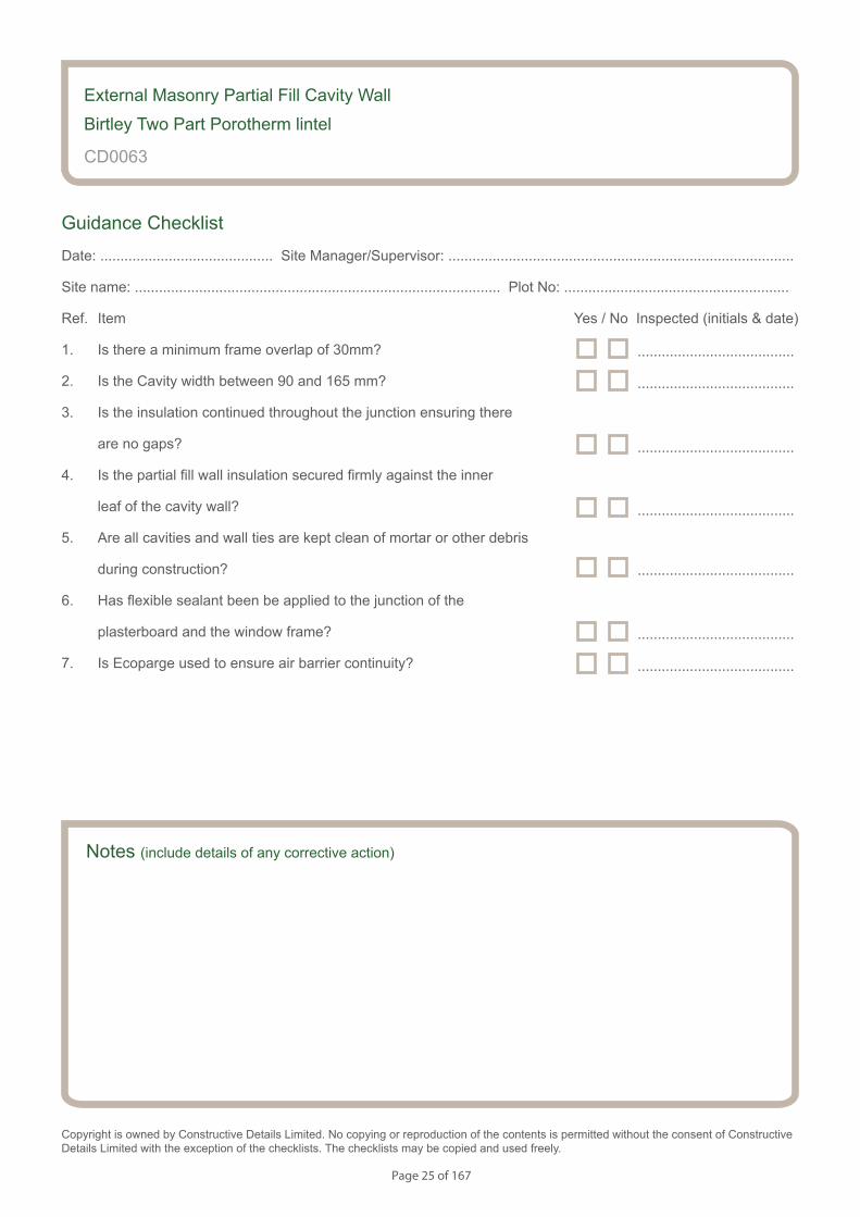
External Masonry Partial Fill Cavity Wall
Birtley Two Part Porotherm lintel
CD0063
Guidance Checklist
Date: ........................................... Site Manager/Supervisor: ......................................................................................
Site name: ........................................................................................... Plot No: ........................................................
Ref. Item Yes / No Inspected (initials & date)
1. Is there a minimum frame overlap of 30mm?
2. Is the Cavity width between 90 and 165 mm?
3. Is the insulation continued throughout the junction ensuring there
are no gaps?
4. Is the partial fill wall insulation secured firmly against the inner
leaf of the cavity wall?
5. Are all cavities and wall ties are kept clean of mortar or other debris
during construction?
6. Has flexible sealant been be applied to the junction of the
plasterboard and the window frame?
7. Is Ecoparge used to ensure air barrier continuity?
Copyright is owned by Constructive Details Limited. No copying or reproduction of the contents is permitted without the consent of Constructive Details Limited with the exception of the checklists. The checklists may be copied and used freely.
.......................................
.......................................
.......................................
.......................................
.......................................
.......................................
.......................................

Page 26 of 167
S154083_CD6-1
Catnic lintel
Notes
• Minimum frame overlap of 30mm
• Cavity width between 90 and 165 mm (range covered by Catnic lintels)
• Ensure continuity of the insulation throughout the junction leaving no gaps
• Ensure that the partial fill wall insulation is secured firmly against the inner leaf of the cavity wall
• Ensure cavities and wall ties are kept clean of mortar or other debris during construction
• Flexible sealant should be applied to the junction of the plasterboard and the window frame
• the use of Ecoparge will ensure air barrier continuity
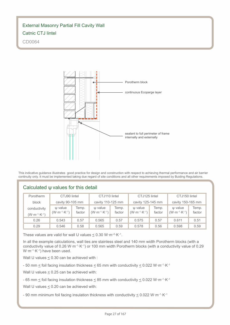
External Masonry Partial Fill Cavity Wall
Catnic CTJ lintel
CD0064
This indicative guidance illustrates good practice for design and construction with respect to achieving thermal performance and air barrier continuity only. It must be implemented taking due regard of site conditions and all other requirements imposed by Buiding Regulations.
minimum frame overlap 30 mm
cavity width 90-165 mm
insulation inside lintel maximum l=0.038 W·m-1·K-1
Page 27 of 167
S154083_CD6-2
Catnic lintel
External Masonry Partial Fill Cavity Wall
Catnic CTJ lintel
CD0064
sealant to full perimeter of frame internally and externally
This indicative guidance illustrates good practice for design and construction with respect to achieving thermal performance and air barrier continuity only. It must be implemented taking due regard of site conditions and all other requirements imposed by Buiding Regulations.
continuous Ecoparge layer
Porotherm block
Calculated ψ values for this detailPorotherm
block
conductivity
(W·m–1·K–1)
CTJ90 lintel
cavity 90-105 mm
CTJ110 lintel
cavity 110-125 mm
CTJ125 lintel
cavity 125-145 mm
CTJ150 lintel
cavity 150-165 mmψ value
(W·m–1·K–1)Temp.factor
ψ value (W·m–1·K–1)
Temp.factor
ψ value (W·m–1·K–1)
Temp.factor
ψ value (W·m–1·K–1)
Temp.factor
0.26 0.543 0.57 0.565 0.57 0.575 0.57 0.611 0.51
0.29 0.546 0.58 0.565 0.59 0.578 0.56 0.598 0.59
These values are valid for wall U values < 0.30 W·m–2·K–1.
In all the example calculations, wall ties are stainless steel and 140 mm width Porotherm blocks (with a conductivity value of 0.26 W·m–1·K–1) or 100 mm width Porotherm blocks (with a conductivity value of 0.29 W·m–1·K–1) have been used.
Wall U values < 0.30 can be achieved with :
- 50 mm < foil facing insulation thickness < 65 mm with conductivity < 0.022 W·m–1·K–1
Wall U values < 0.25 can be achieved with:
- 65 mm < foil facing insulation thickness < 85 mm with conductivity < 0.022 W·m–1·K–1
Wall U values < 0.20 can be achieved with:
- 90 mm minimum foil facing insulation thickness with conductivity < 0.022 W·m–1·K–1
Page 28 of 167
Notes (include details of any corrective action)
External Masonry Partial Fill Cavity Wall
Catnic CTJ lintel
CD0064
Guidance Checklist
Date: ........................................... Site Manager/Supervisor: ......................................................................................
Site name: ........................................................................................... Plot No: ........................................................
Ref. Item Yes / No Inspected (initials & date)
1. Is there a minimum frame overlap of 30mm?
2. Is the Cavity width between 90 and 165 mm?
3. Is the insulation continued throughout the junction ensuring there
are no gaps?
4. Is the partial fill wall insulation secured firmly against the inner
leaf of the cavity wall?
5. Are all cavities and wall ties are kept clean of mortar or other debris
during construction?
6. Has flexible sealant been be applied to the junction of the
plasterboard and the window frame?
7. Is Ecoparge used to ensure air barrier continuity?
Copyright is owned by Constructive Details Limited. No copying or reproduction of the contents is permitted without the consent of Constructive Details Limited with the exception of the checklists. The checklists may be copied and used freely.
.......................................
.......................................
.......................................
.......................................
.......................................
.......................................
.......................................

Page 29 of 167
S154083_CD7-1
Porocav lintel
Notes
• Minimum frame overlap of 30mm
• Cavity width between 90 and 165 mm (range covered by Porocav lintels)
• Ensure continuity of the insulation throughout the junction leaving no gaps
• Ensure that the partial fill wall insulation is secured firmly against the inner leaf of the cavity wall
• Ensure cavities and wall ties are kept clean of mortar or other debris during construction
• Flexible sealant should be applied to the junction of the plasterboard and the window frame
• the use of Ecoparge will ensure air barrier continuity
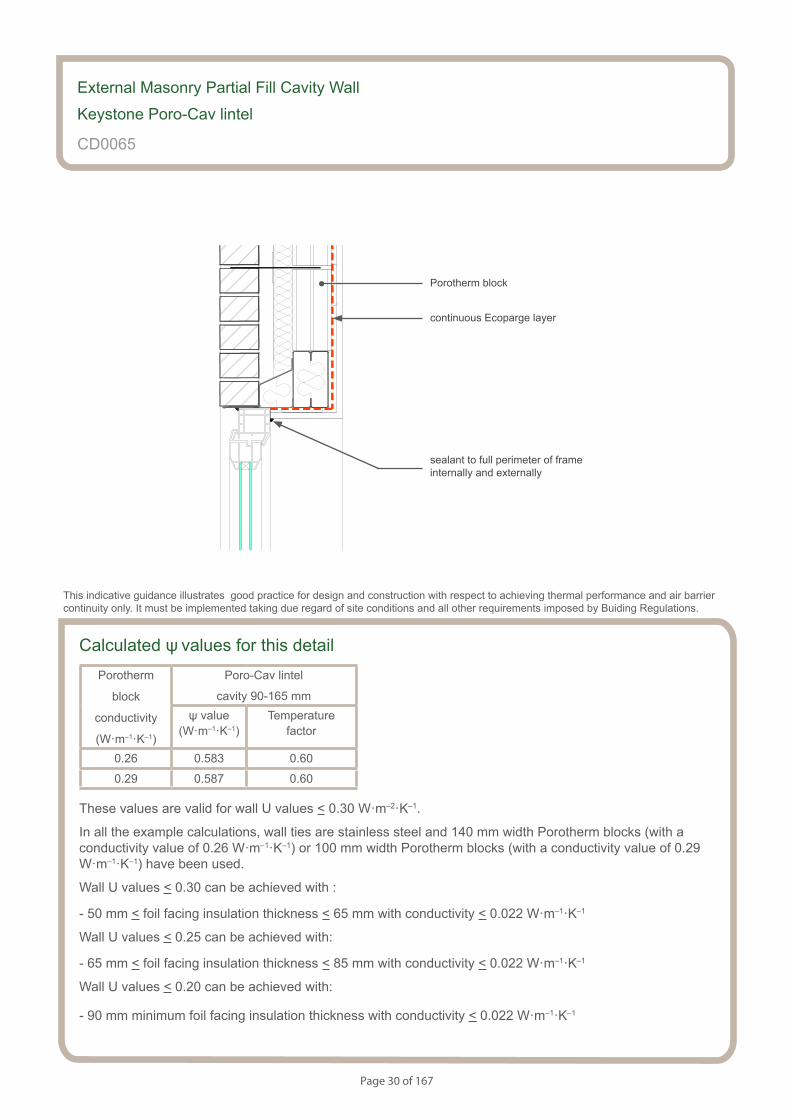
External Masonry Partial Fill Cavity Wall
Keystone Poro-Cav lintel
CD0065
This indicative guidance illustrates good practice for design and construction with respect to achieving thermal performance and air barrier continuity only. It must be implemented taking due regard of site conditions and all other requirements imposed by Buiding Regulations.
minimum frame overlap 30 mm
cavity width 90-165 mm
insulation inside lintel maximum l=0.035 W·m-1·K-1
Page 30 of 167
S154083_CD7-2
Porocav lintel
External Masonry Partial Fill Cavity Wall
Keystone Poro-Cav lintel
CD0065
sealant to full perimeter of frame internally and externally
This indicative guidance illustrates good practice for design and construction with respect to achieving thermal performance and air barrier continuity only. It must be implemented taking due regard of site conditions and all other requirements imposed by Buiding Regulations.
continuous Ecoparge layer
Porotherm block
Calculated ψ values for this detailPorotherm
block
conductivity
(W·m–1·K–1)
Poro-Cav lintel
cavity 90-165 mmψ value
(W·m–1·K–1)Temperature
factor
0.26 0.583 0.60
0.29 0.587 0.60
These values are valid for wall U values < 0.30 W·m–2·K–1.
In all the example calculations, wall ties are stainless steel and 140 mm width Porotherm blocks (with a conductivity value of 0.26 W·m–1·K–1) or 100 mm width Porotherm blocks (with a conductivity value of 0.29 W·m–1·K–1) have been used.
Wall U values < 0.30 can be achieved with :
- 50 mm < foil facing insulation thickness < 65 mm with conductivity < 0.022 W·m–1·K–1
Wall U values < 0.25 can be achieved with:
- 65 mm < foil facing insulation thickness < 85 mm with conductivity < 0.022 W·m–1·K–1
Wall U values < 0.20 can be achieved with:
- 90 mm minimum foil facing insulation thickness with conductivity < 0.022 W·m–1·K–1
Page 31 of 167
Notes (include details of any corrective action)
External Masonry Partial Fill Cavity Wall
Keystone Poro-Cav lintel
CD0065
Guidance Checklist
Date: ........................................... Site Manager/Supervisor: ......................................................................................
Site name: ........................................................................................... Plot No: ........................................................
Ref. Item Yes / No Inspected (initials & date)
1. Is there a minimum frame overlap of 30mm?
2. Is the Cavity width between 90 and 165 mm?
3. Is the insulation continued throughout the junction ensuring there
are no gaps?
4. Is the partial fill wall insulation secured firmly against the inner
leaf of the cavity wall?
5. Are all cavities and wall ties are kept clean of mortar or other debris
during construction?
6. Has flexible sealant been be applied to the junction of the
plasterboard and the window frame?
7. Is Ecoparge used to ensure air barrier continuity?
Copyright is owned by Constructive Details Limited. No copying or reproduction of the contents is permitted without the consent of Constructive Details Limited with the exception of the checklists. The checklists may be copied and used freely.
.......................................
.......................................
.......................................
.......................................
.......................................
.......................................
.......................................

Page 32 of 167
S154083_CD8-1
Box and angle lintel
Notes
• PVC-U cavity closer fully insulated with conductivity 0.038 W/mK or less
• Maximum conductivity of insulation inside lintel box 0.038 W/mK
• Minimum frame overlap of 30mm
• Maximum cavity width 200 mm
• Ensure continuity of the insulation throughout the junction leaving no gaps
• Ensure that the partial fill wall insulation is secured firmly against the inner leaf of the cavity wall
• Ensure cavities and wall ties are kept clean of mortar or other debris during construction
• Flexible sealant should be applied to the junction of the plasterboard and the window frame
• the use of Ecoparge will ensure air barrier continuity
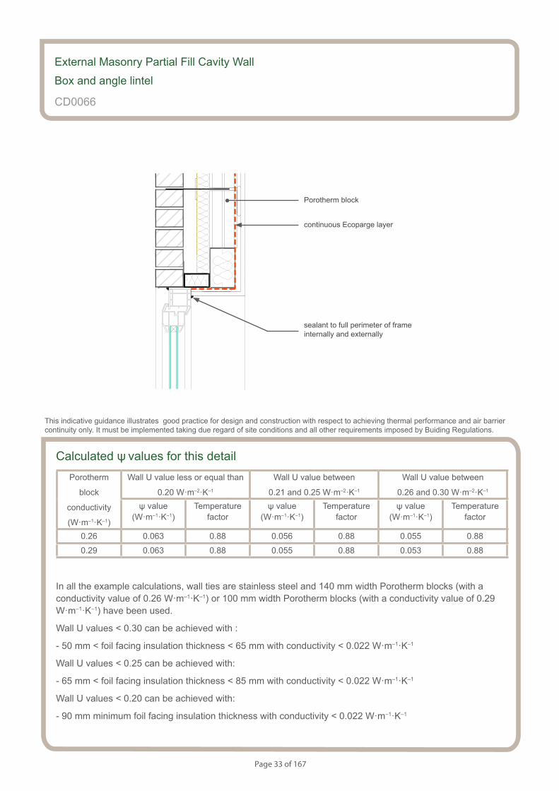
External Masonry Partial Fill Cavity Wall
Box and angle lintel
CD0066
This indicative guidance illustrates good practice for design and construction with respect to achieving thermal performance and air barrier continuity only. It must be implemented taking due regard of site conditions and all other requirements imposed by Buiding Regulations.
minimum frame overlap 30 mm
maximum cavity width 200mm
insulation inside lintel maximum l=0.038 W·m-1·K-1
PVC-U cavity closer fully insulated with a conductivity less or equal than 0.038 W·m–1·K–1
Page 33 of 167
S154083_CD8-2
Box and angle lintel
Calculated ψ values for this detailPorotherm
block
conductivity
(W·m–1·K–1)
Wall U value less or equal than
0.20 W·m–2·K–1
Wall U value between
0.21 and 0.25 W·m–2·K–1
Wall U value between
0.26 and 0.30 W·m–2·K–1
ψ value (W·m–1·K–1)
Temperaturefactor
ψ value (W·m–1·K–1)
Temperaturefactor
ψ value (W·m–1·K–1)
Temperaturefactor
0.26 0.063 0.88 0.056 0.88 0.055 0.88
0.29 0.063 0.88 0.055 0.88 0.053 0.88
In all the example calculations, wall ties are stainless steel and 140 mm width Porotherm blocks (with a conductivity value of 0.26 W·m–1·K–1) or 100 mm width Porotherm blocks (with a conductivity value of 0.29 W·m–1·K–1) have been used.
Wall U values < 0.30 can be achieved with :
- 50 mm < foil facing insulation thickness < 65 mm with conductivity < 0.022 W·m–1·K–1
Wall U values < 0.25 can be achieved with:
- 65 mm < foil facing insulation thickness < 85 mm with conductivity < 0.022 W·m–1·K–1
Wall U values < 0.20 can be achieved with:
- 90 mm minimum foil facing insulation thickness with conductivity < 0.022 W·m–1·K–1
External Masonry Partial Fill Cavity Wall
Box and angle lintel
CD0066
sealant to full perimeter of frame internally and externally
This indicative guidance illustrates good practice for design and construction with respect to achieving thermal performance and air barrier continuity only. It must be implemented taking due regard of site conditions and all other requirements imposed by Buiding Regulations.
continuous Ecoparge layer
Porotherm block
Page 34 of 167
Notes (include details of any corrective action)
External Masonry Partial Fill Cavity Wall
Box and angle lintel
CD0066
Guidance Checklist
Date: ........................................... Site Manager/Supervisor: ......................................................................................
Site name: ........................................................................................... Plot No: ........................................................
Ref. Item Yes / No Inspected (initials & date)
1. Is the PVC-U cavity closer fully insulated with conductivity
0.038 W/mK or less?
2. Is the maximum conductivity of the insulation inside lintel
box 0.038 W/mK?
3. Is the minimum frame overlap of 30mm?
4. Is the maximum cavity width 200 mm?
5. Is the insulation continued throughout the junction ensuring no gaps?
6. Is the partial fill wall insulation secured firmly against the inner leaf
of the cavity wall?
7. Are all cavities and wall ties are kept clean of mortar or other debris
during construction?
8. Is there flexible sealant applied to the junction of the plasterboard
and the window frame?
9. Is Ecoparge used to ensure air barrier continuity?
Copyright is owned by Constructive Details Limited. No copying or reproduction of the contents is permitted without the consent of Constructive Details Limited with the exception of the checklists. The checklists may be copied and used freely.
.......................................
.......................................
.......................................
.......................................
.......................................
.......................................
.......................................
.......................................
.......................................
Page 35 of 167
Notes
• PVC-U cavity closer fully insulated with conductivity 0.038 W/mK or less
• Minimum frame overlap of 30mm
• Maximum cavity width 200mm
• ensure continuity of the insulation throughout the junction leaving no gaps
• ensure that the partial fill wall insulation is secured firmly against the inner leaf of the cavity wall
• ensure cavities and wall ties are kept clean of mortar or other debris during construction
• flexible sealant should be applied to the junction of the plasterboard and the sill board as well as between the window frame member and sill board
• the use of Ecoparge will ensure air barrier continuity
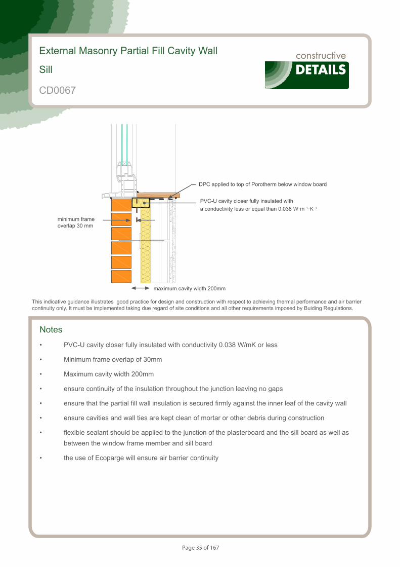
External Masonry Partial Fill Cavity Wall
Sill
CD0067
This indicative guidance illustrates good practice for design and construction with respect to achieving thermal performance and air barrier continuity only. It must be implemented taking due regard of site conditions and all other requirements imposed by Buiding Regulations.
minimum frame overlap 30 mm
maximum cavity width 200mm
PVC-U cavity closer fully insulated with a conductivity less or equal than 0.038 W·m–1·K–1
DPC applied to top of Porotherm below window board

Page 36 of 167
Calculated ψ values for this detailPorotherm
block
conductivity
(W·m–1·K–1)
Wall U value less or equal than
0.20 W·m–2·K–1
Wall U value between
0.21 and 0.25 W·m–2·K–1
Wall U value between
0.26 and 0.30 W·m–2·K–1
ψ value (W·m–1·K–1)
Temperaturefactor
ψ value (W·m–1·K–1)
Temperaturefactor
ψ value (W·m–1·K–1)
Temperaturefactor
0.26 0.050 0.82 0.045 0.82 0.042 0.82
0.29 0.049 0.82 0.045 0.82 0.041 0.82
In all the example calculations, wall ties are stainless steel and 140 mm width Porotherm blocks (with a conductivity value of 0.26 W·m–1·K–1) or 100 mm width Porotherm blocks (with a conductivity value of 0.29 W·m–1·K–1) have been used.
Wall U values < 0.30 can be achieved with :
- 50 mm < foil facing insulation thickness < 65 mm with conductivity < 0.022 W·m–1·K–1
Wall U values < 0.25 can be achieved with:
- 65 mm < foil facing insulation thickness < 85 mm with conductivity < 0.022 W·m–1·K–1
Wall U values < 0.20 can be achieved with:
- 90 mm minimum foil facing insulation thickness with conductivity < 0.022 W·m–1·K–1
External Masonry Partial Fill Cavity Wall
Sill
CD0067
sealant to full perimeter of frame and sill internally and externally
This indicative guidance illustrates good practice for design and construction with respect to achieving thermal performance and air barrier continuity only. It must be implemented taking due regard of site conditions and all other requirements imposed by Buiding Regulations.
sealant between sill and plasterboard
continuous Ecoparge layer
Porotherm block
Page 37 of 167
Notes (include details of any corrective action)
External Masonry Partial Fill Cavity Wall
Sill
CD0067
Guidance Checklist
Date: ........................................... Site Manager/Supervisor: ......................................................................................
Site name: ........................................................................................... Plot No: ........................................................
Ref. Item Yes / No Inspected (initials & date)
1. Is the PVC-U cavity closer fully insulated with conductivity of
0.038 W/mK or less?
2. Is there a minimum frame overlap of 30mm?
3. Is there a maximum cavity width 200mm?
4. Is there continuity of the insulation throughout the junction
leaving no gaps?
5. Is the partial fill wall insulation is secured firmly against the inner
leaf of the cavity wall
6. Are the cavities and wall ties are kept clean of mortar or other debris?
7. Is flexible sealant applied to the junction of the plasterboard and
the sill board as well as between the window frame and sill board?
8. Is Ecoparge applied to ensure air barrier continuity?
Copyright is owned by Constructive Details Limited. No copying or reproduction of the contents is permitted without the consent of Constructive Details Limited with the exception of the checklists. The checklists may be copied and used freely.
.......................................
.......................................
.......................................
.......................................
.......................................
.......................................
.......................................
Page 38 of 167
Notes
• PVC-U cavity closer fully insulated with conductivity 0.038 W/mK or less
• Minimum frame overlap of 30mm
• Maximum cavity width 200mm
• ensure continuity of the insulation throughout the junction leaving no gaps
• ensure that the partial fill wall insulation is secured firmly against the inner leaf of the cavity wall
• ensure cavities and wall ties are kept clean of mortar or other debris during construction
• flexible sealant should be applied to the junction of the plasterboard and the sill board as well as between the window frame member and sill board
• the use of Ecoparge will ensure air barrier continuity
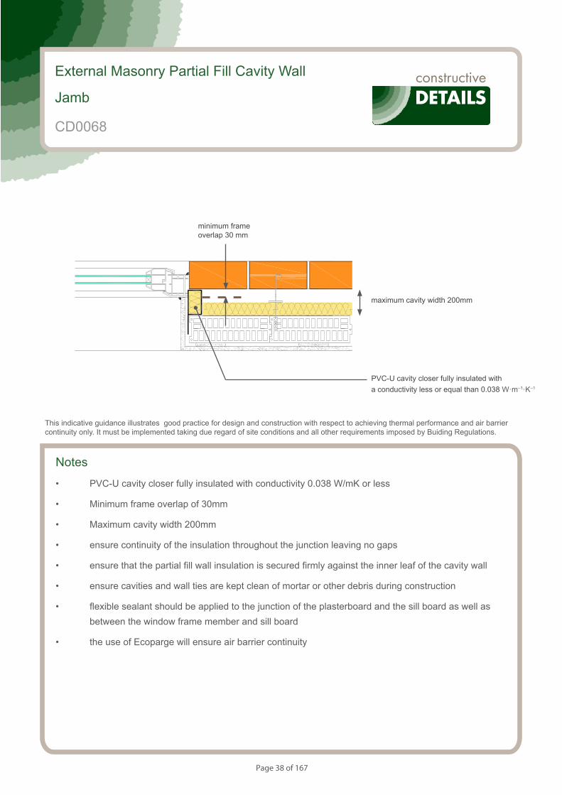
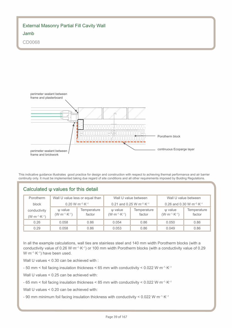
External Masonry Partial Fill Cavity Wall
Jamb
CD0068
This indicative guidance illustrates good practice for design and construction with respect to achieving thermal performance and air barrier continuity only. It must be implemented taking due regard of site conditions and all other requirements imposed by Buiding Regulations.
minimum frame overlap 30 mm
maximum cavity width 200mm
PVC-U cavity closer fully insulated with a conductivity less or equal than 0.038 W·m–1·K–1
Page 39 of 167
Calculated ψ values for this detailPorotherm
block
conductivity
(W·m–1·K–1)
Wall U value less or equal than
0.20 W·m–2·K–1
Wall U value between
0.21 and 0.25 W·m–2·K–1
Wall U value between
0.26 and 0.30 W·m–2·K–1
ψ value (W·m–1·K–1)
Temperaturefactor
ψ value (W·m–1·K–1)
Temperaturefactor
ψ value (W·m–1·K–1)
Temperaturefactor
0.26 0.058 0.86 0.054 0.86 0.050 0.86
0.29 0.058 0.86 0.053 0.86 0.049 0.86
In all the example calculations, wall ties are stainless steel and 140 mm width Porotherm blocks (with a conductivity value of 0.26 W·m–1·K–1) or 100 mm width Porotherm blocks (with a conductivity value of 0.29 W·m–1·K–1) have been used.
Wall U values < 0.30 can be achieved with :
- 50 mm < foil facing insulation thickness < 65 mm with conductivity < 0.022 W·m–1·K–1
Wall U values < 0.25 can be achieved with:
- 65 mm < foil facing insulation thickness < 85 mm with conductivity < 0.022 W·m–1·K–1
Wall U values < 0.20 can be achieved with:
- 90 mm minimum foil facing insulation thickness with conductivity < 0.022 W·m–1·K–1
External Masonry Partial Fill Cavity Wall
Jamb
CD0068
perimeter sealant between frame and brickwork
This indicative guidance illustrates good practice for design and construction with respect to achieving thermal performance and air barrier continuity only. It must be implemented taking due regard of site conditions and all other requirements imposed by Buiding Regulations.
perimeter sealant between frame and plasterboard
continuous Ecoparge layer
Porotherm block
Page 40 of 167
Notes (include details of any corrective action)
External Masonry Partial Fill Cavity Wall
Jamb
CD0068
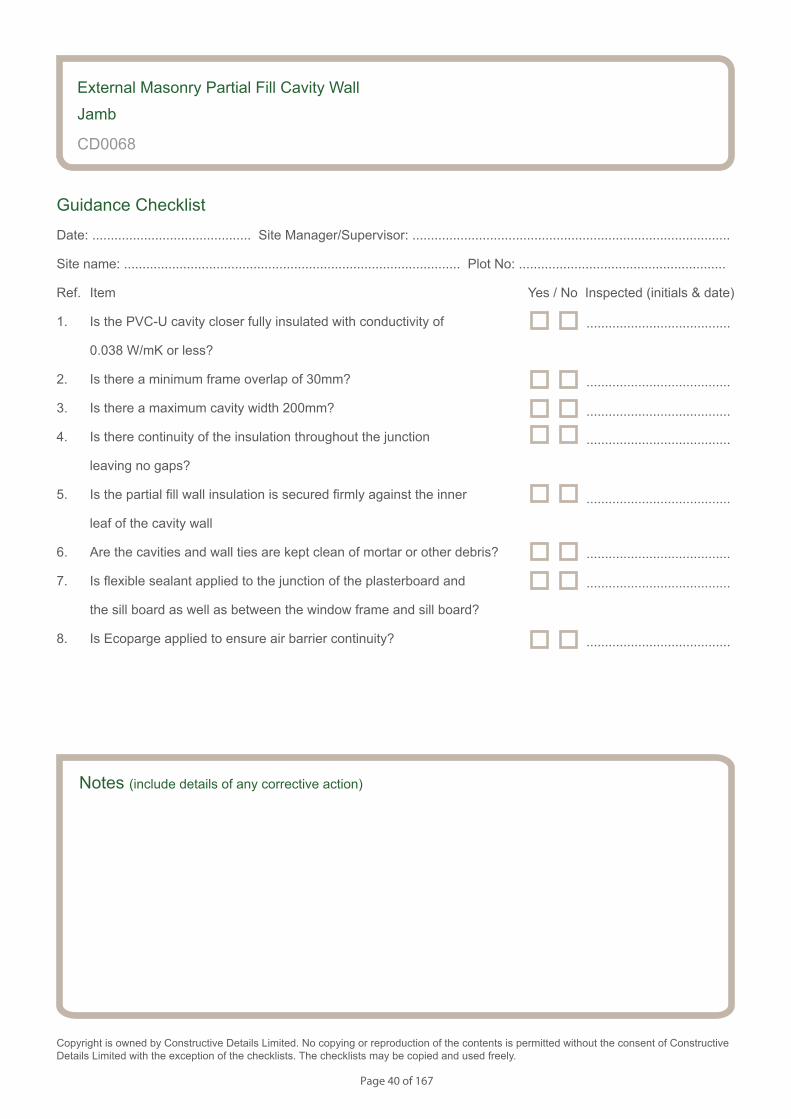
Guidance Checklist
Date: ........................................... Site Manager/Supervisor: ......................................................................................
Site name: ........................................................................................... Plot No: ........................................................
Ref. Item Yes / No Inspected (initials & date)
1. Is the PVC-U cavity closer fully insulated with conductivity of
0.038 W/mK or less?
2. Is there a minimum frame overlap of 30mm?
3. Is there a maximum cavity width 200mm?
4. Is there continuity of the insulation throughout the junction
leaving no gaps?
5. Is the partial fill wall insulation is secured firmly against the inner
leaf of the cavity wall
6. Are the cavities and wall ties are kept clean of mortar or other debris?
7. Is flexible sealant applied to the junction of the plasterboard and
the sill board as well as between the window frame and sill board?
8. Is Ecoparge applied to ensure air barrier continuity?
Copyright is owned by Constructive Details Limited. No copying or reproduction of the contents is permitted without the consent of Constructive Details Limited with the exception of the checklists. The checklists may be copied and used freely.
.......................................
.......................................
.......................................
.......................................
.......................................
.......................................
.......................................
.......................................
Page 41 of 167
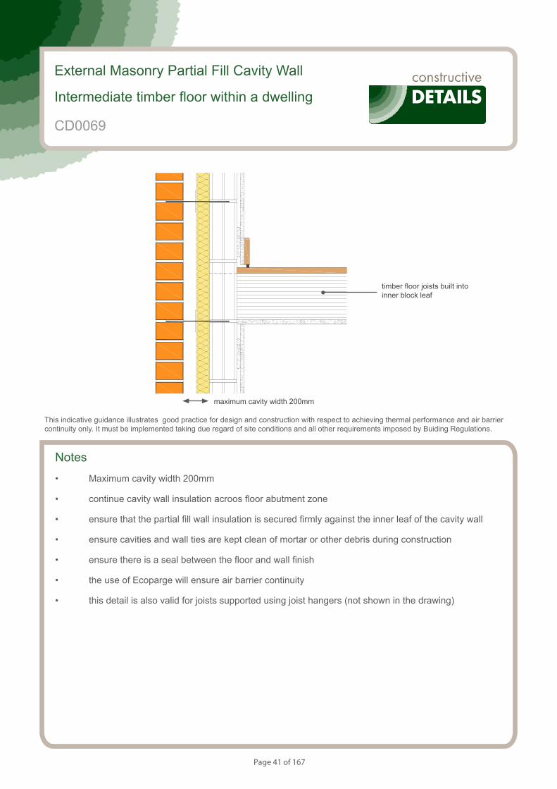
Notes
• Maximum cavity width 200mm
• continue cavity wall insulation acroos floor abutment zone
• ensure that the partial fill wall insulation is secured firmly against the inner leaf of the cavity wall
• ensure cavities and wall ties are kept clean of mortar or other debris during construction
• ensure there is a seal between the floor and wall finish
• the use of Ecoparge will ensure air barrier continuity
• this detail is also valid for joists supported using joist hangers (not shown in the drawing)
External Masonry Partial Fill Cavity Wall
Intermediate timber floor within a dwelling
CD0069
This indicative guidance illustrates good practice for design and construction with respect to achieving thermal performance and air barrier continuity only. It must be implemented taking due regard of site conditions and all other requirements imposed by Buiding Regulations.
maximum cavity width 200mm
timber floor joists built into inner block leaf
Page 42 of 167
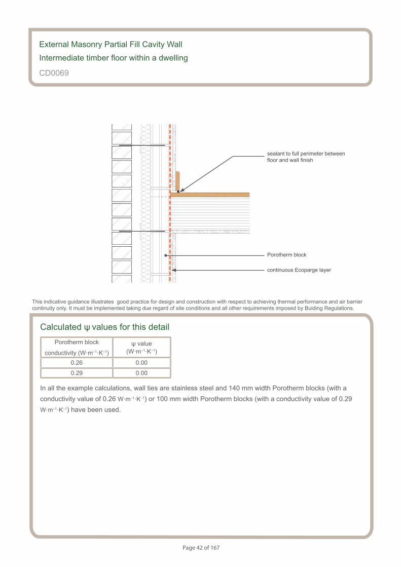
Calculated ψ values for this detailPorotherm block
conductivity (W·m–1·K–1)ψ value
(W·m–1·K–1)
0.26 0.00
0.29 0.00
In all the example calculations, wall ties are stainless steel and 140 mm width Porotherm blocks (with a conductivity value of 0.26 W·m–1·K–1) or 100 mm width Porotherm blocks (with a conductivity value of 0.29 W·m–1·K–1) have been used.
External Masonry Partial Fill Cavity Wall
Intermediate timber floor within a dwelling
CD0069
sealant to full perimeter between floor and wall finish
This indicative guidance illustrates good practice for design and construction with respect to achieving thermal performance and air barrier continuity only. It must be implemented taking due regard of site conditions and all other requirements imposed by Buiding Regulations.
continuous Ecoparge layer
Porotherm block
Page 43 of 167
Notes (include details of any corrective action)
External Masonry Partial Fill Cavity Wall
Intermediate timber floor within a dwelling
CD0069
Guidance Checklist
Date: ........................................... Site Manager/Supervisor: ......................................................................................
Site name: ........................................................................................... Plot No: ........................................................
Ref. Item Yes / No Inspected (initials & date)
1. Is there a maximum cavity width 200mm
2. Does the cavity wall insulation continue across floor abutment zone?
3. Is the partial fill wall insulation is secured firmly against the inner leaf
of the cavity wall?
4. Are cavities and wall ties kept clean of mortar or other debris during
construction?
5. Is there is a seal between the floor and wall finish?
6. Has Ecoparge been used to ensure air barrier continuity?
Copyright is owned by Constructive Details Limited. No copying or reproduction of the contents is permitted without the consent of Constructive Details Limited with the exception of the checklists. The checklists may be copied and used freely.
.......................................
.......................................
.......................................
.......................................
.......................................
.......................................

Page 44 of 167
S154083_CD12-1
Precast concrete separating floor between dwellings
Notes
• Maximum cavity width 200mm
• ensure continuity of the insulation throughout the junction leaving no gaps
• ensure that the partial fill wall insulation is secured firmly against the inner leaf of the cavity wall
• maximum conductivity of the fire stop 0.044 Wm-1K-1
• ensure cavities and wall ties are kept clean of mortar or other debris during construction
• the use of Ecoparge will ensure air barrier continuity
• maximum thickness of screed 75 mm
• maximum thickness of concrete block 225 mm
• maximum suspended ceiling void 150 mm
External Masonry Partial Fill Cavity Wall
Separating concrete floor between dwellings
CD0070
This indicative guidance illustrates good practice for design and construction with respect to achieving thermal performance and air barrier continuity only. It must be implemented taking due regard of site conditions and all other requirements imposed by Buiding Regulations.
maximum cavity width 200mm
maximum suspended ceiling void 150 mm
maximum thickness of concrete block 225 mm
maximum thickness of screed 75 mm
maximum conductivity of fire stop 0.044 Wm-1K-1
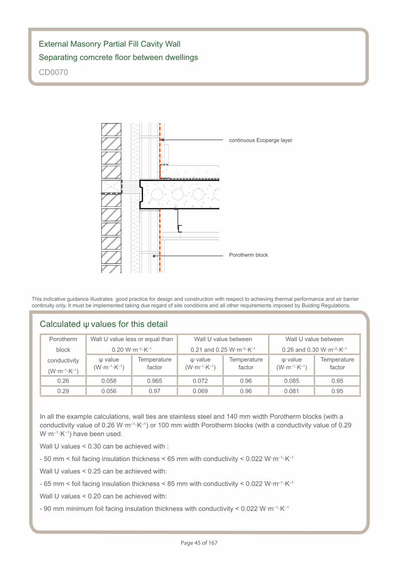
Page 45 of 167
Precast concrete separating floor between dwellings
S154083_CD12-2
Calculated ψ values for this detailPorotherm
block
conductivity
(W·m–1·K–1)
Wall U value less or equal than
0.20 W·m–2·K–1
Wall U value between
0.21 and 0.25 W·m–2·K–1
Wall U value between
0.26 and 0.30 W·m–2·K–1
ψ value (W·m–1·K–1)
Temperaturefactor
ψ value (W·m–1·K–1)
Temperaturefactor
ψ value (W·m–1·K–1)
Temperaturefactor
0.26 0.058 0.965 0.072 0.96 0.085 0.95
0.29 0.056 0.97 0.069 0.96 0.081 0.95
In all the example calculations, wall ties are stainless steel and 140 mm width Porotherm blocks (with a conductivity value of 0.26 W·m–1·K–1) or 100 mm width Porotherm blocks (with a conductivity value of 0.29 W·m–1·K–1) have been used.
Wall U values < 0.30 can be achieved with :
- 50 mm < foil facing insulation thickness < 65 mm with conductivity < 0.022 W·m–1·K–1
Wall U values < 0.25 can be achieved with:
- 65 mm < foil facing insulation thickness < 85 mm with conductivity < 0.022 W·m–1·K–1
Wall U values < 0.20 can be achieved with:
- 90 mm minimum foil facing insulation thickness with conductivity < 0.022 W·m–1·K–1
External Masonry Partial Fill Cavity Wall
Separating comcrete floor between dwellings
CD0070
This indicative guidance illustrates good practice for design and construction with respect to achieving thermal performance and air barrier continuity only. It must be implemented taking due regard of site conditions and all other requirements imposed by Buiding Regulations.
continuous Ecoparge layer
Porotherm block
Page 46 of 167
Notes (include details of any corrective action)
CD0070
Guidance Checklist
Date: ........................................... Site Manager/Supervisor: ......................................................................................
Site name: ........................................................................................... Plot No: ........................................................
Ref. Item Yes / No Inspected (initials & date)
1. Is the precast concrete floor thickness 225 mm or less?
2. Is the concrete screed thickness 75 mm or less?
3. Is the ceiling void thickness 150 mm or less?
4. Is the fire stop conductivity 0.044 W·m-1·K-1 or less?
5. Is the continuity of the insulation throughout the junction achieved?
6. Is the partial fill wall insulation secured firmly?
7. Is the continuity of the air barrier between the floor and the wall
achieved? If not, please provide details.
Copyright is owned by Constructive Details Limited. No copying or reproduction of the contents is permitted without the consent of Constructive Details Limited with the exception of the checklists. The checklists may be copied and used freely.
.......................................
.......................................
.......................................
.......................................
.......................................
.......................................
External Masonry Partial Fill Cavity Wall
Separating concrete floor between dwellings
.......................................

Page 47 of 167
S154083_CD13-1
Pitched roof.Gable - insulation at ceiling level - Ventilated loft
Notes
• Maximum cavity width 200mm
• ensure continuity of the insulation throughout the junction leaving no gaps
• ensure that the partial fill wall insulation is secured firmly against the inner leaf of the cavity wall
• maximum conductivity of the fire stop 0.044 Wm-1K-1
• ensure cavities and wall ties are kept clean of mortar or other debris during construction
• the use of Ecoparge will ensure air barrier continuity
• minimum conductivity of wall insulation above ceiling insulation 200 mm
External Masonry Partial Fill Cavity Wall
Pitched roof. Gable - Insulation at ceiling level
CD0071
This indicative guidance illustrates good practice for design and construction with respect to achieving thermal performance and air barrier continuity only. It must be implemented taking due regard of site conditions and all other requirements imposed by Buiding Regulations.
maximum cavity width 200mm
minimum continuity of wall insulation above ceiling insulation 200 mm
total ceiling insulation thickness between 210 and 510 mm with a maximum conductivity of 0.044 W·m-1·K-1
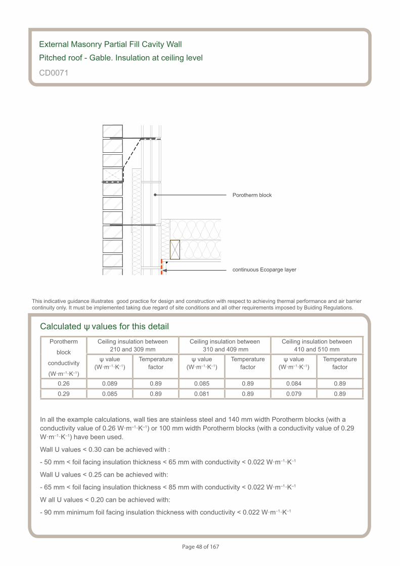
Page 48 of 167
Pitched roof.Gable - insulation at ceiling level - Ventilated loft
S154083_CD13-2
Calculated ψ values for this detailPorotherm
block
conductivity
(W·m–1·K–1)
Ceiling insulation between 210 and 309 mm
Ceiling insulation between 310 and 409 mm
Ceiling insulation between410 and 510 mm
ψ value (W·m–1·K–1)
Temperaturefactor
ψ value (W·m–1·K–1)
Temperaturefactor
ψ value (W·m–1·K–1)
Temperaturefactor
0.26 0.089 0.89 0.085 0.89 0.084 0.89
0.29 0.085 0.89 0.081 0.89 0.079 0.89
In all the example calculations, wall ties are stainless steel and 140 mm width Porotherm blocks (with a conductivity value of 0.26 W·m–1·K–1) or 100 mm width Porotherm blocks (with a conductivity value of 0.29 W·m–1·K–1) have been used.
Wall U values < 0.30 can be achieved with :
- 50 mm < foil facing insulation thickness < 65 mm with conductivity < 0.022 W·m–1·K–1
Wall U values < 0.25 can be achieved with:
- 65 mm < foil facing insulation thickness < 85 mm with conductivity < 0.022 W·m–1·K–1
W all U values < 0.20 can be achieved with:
- 90 mm minimum foil facing insulation thickness with conductivity < 0.022 W·m–1·K–1
External Masonry Partial Fill Cavity Wall
Pitched roof - Gable. Insulation at ceiling level
CD0071
This indicative guidance illustrates good practice for design and construction with respect to achieving thermal performance and air barrier continuity only. It must be implemented taking due regard of site conditions and all other requirements imposed by Buiding Regulations.
continuous Ecoparge layer
Porotherm block

Page 49 of 167
Notes (include details of any corrective action)
CD0071
Guidance Checklist
Date: ........................................... Site Manager/Supervisor: ......................................................................................
Site name: ........................................................................................... Plot No: ........................................................
Ref. Item Yes / No Inspected (initials & date)
1. Is the ceiling insulation thickness between 210 and 510 mm
and has a maximum conductivity of 0.044 W·m-1·K-1?
2. Is the gap between the first joint and the gable wall fully insulated?
3. Is the partial fill insulation continued to at least 200 mm above the top
of the ceiling insulation?
5. If a cavity tray was used, does the full fill inulation fit tightly against
the cavity tray, with no gaps?
6. Is the continuity of the insulation through the junction achieved?
7. Is the wall partial fill insulation secured firmly?
8. Is the continuity of the air barrier achieved? If not, please provide
details.
Copyright is owned by Constructive Details Limited. No copying or reproduction of the contents is permitted without the consent of Constructive Details Limited with the exception of the checklists. The checklists may be copied and used freely.
.......................................
.......................................
.......................................
.......................................
.......................................
.......................................
.......................................
External Masonry Partial Fill Cavity Wall
Pitched roof - Gable. Insulation at ceiling level

Page 50 of 167
Pitched roof.Gable - insulation at rafter level - Unventilated rafter void
S154083_CD14-1
Notes
• Maximum cavity width 200mm
• ensure continuity of the insulation throughout the junction leaving no gaps
• ensure that the partial fill wall insulation is secured firmly against the inner leaf of the cavity wall
• fill the void between the top of the gable and the underside of the breathable roof membrane with a minimum of 100 mm of insulation with a maximum conductivity of 0.036 Wm-1K-1. Also fill the gap between the rafter and the wall.
• use minimum 150 mm rafters, with void between them fully filled with insulation of a maximum conductivity of 0.036 Wm-1K-1
• minimum 25 mm of insulation below rafters, with a maximum conductivity of 0.030 Wm-1K-1
• ensure cavities and wall ties are kept clean of mortar or other debris during construction
• the use of Ecoparge will ensure air barrier continuity
External Masonry Partial Fill Cavity Wall
Pitched roof. Gable - Insulation at rafter level
CD0072
This indicative guidance illustrates good practice for design and construction with respect to achieving thermal performance and air barrier continuity only. It must be implemented taking due regard of site conditions and all other requirements imposed by Buiding Regulations.
maximum cavity width 200mm
minimum 150 mm rafters, void fully filled with insulation maximum conductivity 0.036 Wm-1K-1
breathable roof membrane
fill void with minimum 100 mm of insulation maximum conductivity 0.036 Wm-1K-1
minimum 25 mm insulation below rafters maximum conductivity 0.030 Wm-1K-1
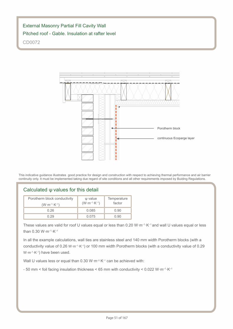
Page 51 of 167
S154083_CD14-2
Pitched roof.Gable - insulation at rafter level - Unventilated rafter void
Calculated ψ values for this detailPorotherm block conductivity
(W·m–1·K–1)
ψ value (W·m–1·K–1)
Temperaturefactor
0.26 0.085 0.90
0.29 0.075 0.90
These values are valid for roof U values equal or less than 0.20 W·m–1·K–1 and wall U values equal or less than 0.30 W·m–1·K–1
In all the example calculations, wall ties are stainless steel and 140 mm width Porotherm blocks (with a conductivity value of 0.26 W·m–1·K–1) or 100 mm width Porotherm blocks (with a conductivity value of 0.29 W·m–1·K–1) have been used.
Wall U values less or equal than 0.30 W·m–2·K–1 can be achieved with:
- 50 mm < foil facing insulation thickness < 65 mm with conductivity < 0.022 W·m–1·K–1
External Masonry Partial Fill Cavity Wall
Pitched roof - Gable. Insulation at rafter level
CD0072
This indicative guidance illustrates good practice for design and construction with respect to achieving thermal performance and air barrier continuity only. It must be implemented taking due regard of site conditions and all other requirements imposed by Buiding Regulations.
continuous Ecoparge layer
Porotherm block
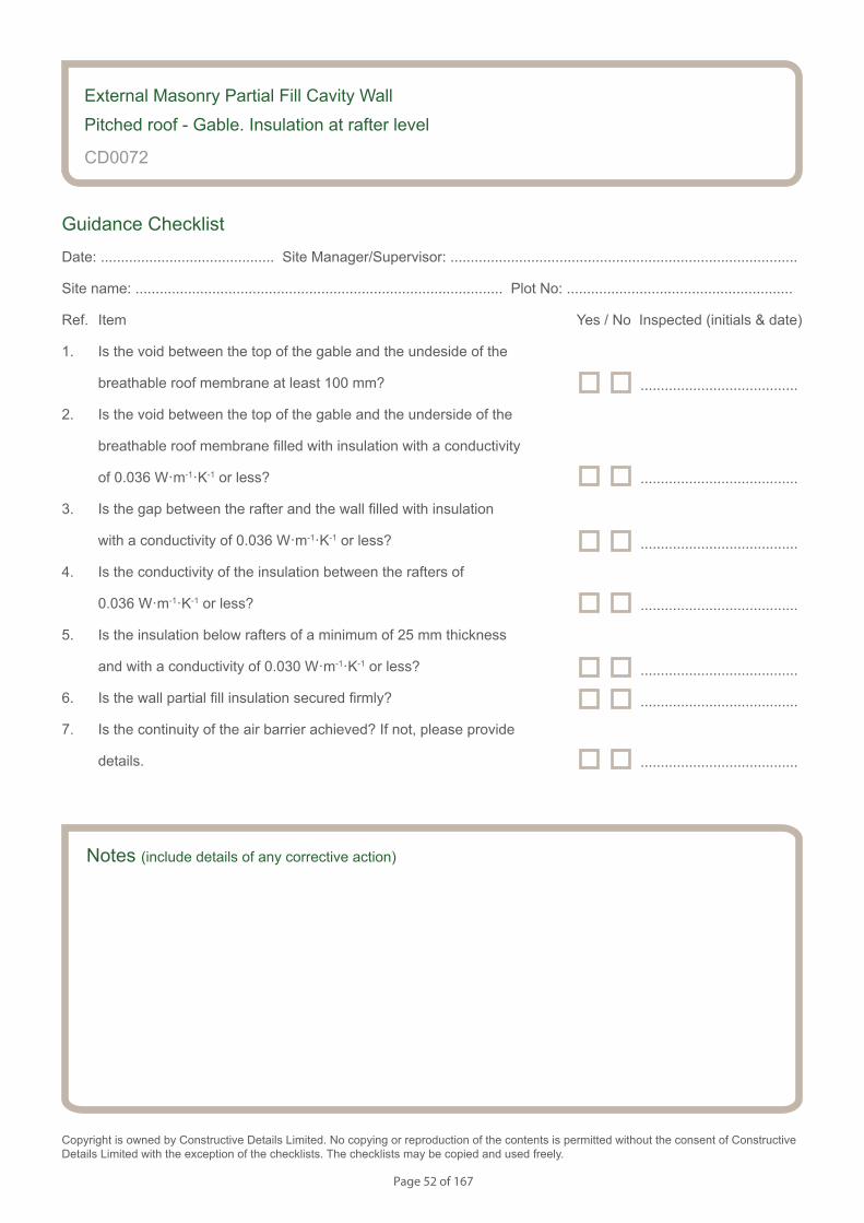
Page 52 of 167
Notes (include details of any corrective action)
CD0072
Guidance Checklist
Date: ........................................... Site Manager/Supervisor: ......................................................................................
Site name: ........................................................................................... Plot No: ........................................................
Ref. Item Yes / No Inspected (initials & date)
1. Is the void between the top of the gable and the undeside of the
breathable roof membrane at least 100 mm?
2. Is the void between the top of the gable and the underside of the
breathable roof membrane filled with insulation with a conductivity
of 0.036 W·m-1·K-1 or less?
3. Is the gap between the rafter and the wall filled with insulation
with a conductivity of 0.036 W·m-1·K-1 or less?
4. Is the conductivity of the insulation between the rafters of
0.036 W·m-1·K-1 or less?
5. Is the insulation below rafters of a minimum of 25 mm thickness
and with a conductivity of 0.030 W·m-1·K-1 or less?
6. Is the wall partial fill insulation secured firmly?
7. Is the continuity of the air barrier achieved? If not, please provide
details.
Copyright is owned by Constructive Details Limited. No copying or reproduction of the contents is permitted without the consent of Constructive Details Limited with the exception of the checklists. The checklists may be copied and used freely.
.......................................
.......................................
.......................................
.......................................
.......................................
.......................................
.......................................
External Masonry Partial Fill Cavity Wall
Pitched roof - Gable. Insulation at rafter level
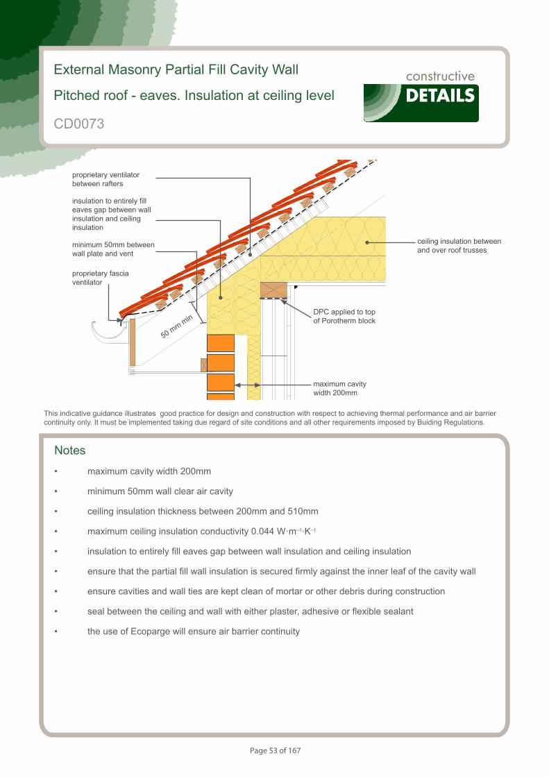
Page 53 of 167
S154083_CD15-1
Pitched roof. Eaves - Insulation at ceiling level - Ventilated loft
Notes
• maximum cavity width 200mm
• minimum 50mm wall clear air cavity
• ceiling insulation thickness between 200mm and 510mm
• maximum ceiling insulation conductivity 0.044 W·m–1·K–1
• insulation to entirely fill eaves gap between wall insulation and ceiling insulation
• ensure that the partial fill wall insulation is secured firmly against the inner leaf of the cavity wall
• ensure cavities and wall ties are kept clean of mortar or other debris during construction
• seal between the ceiling and wall with either plaster, adhesive or flexible sealant
• the use of Ecoparge will ensure air barrier continuity
External Masonry Partial Fill Cavity Wall
Pitched roof - eaves. Insulation at ceiling level
This indicative guidance illustrates good practice for design and construction with respect to achieving thermal performance and air barrier continuity only. It must be implemented taking due regard of site conditions and all other requirements imposed by Buiding Regulations.
maximum cavity width 200mm
ceiling insulation between and over roof trusses
proprietary ventilator between rafters
insulation to entirely fill eaves gap between wall insulation and ceiling insulation
minimum 50mm between wall plate and vent
proprietary fascia ventilator
50 mm min
CD0073
DPC applied to top of Porotherm block

Page 54 of 167
S154083_CD15-2
Pitched roof. Eaves - Insulation at ceiling level - Ventilated loft
Calculated ψ values for this detail
Ceiling insulation thickness between 200mm and 310mm
Porotherm
block
conductivity
(W·m–1·K–1)
Wall U value less or equal than
0.20 W·m–2·K–1
Wall U value between
0.21 and 0.25 W·m–2·K–1
Wall U value between
0.26 and 0.30 W·m–2·K–1
ψ value (W·m–1·K–1)
Temperaturefactor
ψ value (W·m–1·K–1)
Temperaturefactor
ψ value (W·m–1·K–1)
Temperaturefactor
0.26 0.108 0.92 0.099 0.92 0.094 0.92
0.29 0.119 0.92 0.103 0.91 0.104 0.91
Ceiling insulation thickness between 311mm and 410mm
Porotherm
block
conductivity
(W·m–1·K–1)
Wall U value less or equal than
0.20 W·m–2·K–1
Wall U value between
0.21 and 0.25 W·m–2·K–1
Wall U value between
0.26 and 0.30 W·m–2·K–1
ψ value (W·m–1·K–1)
Temperaturefactor
ψ value (W·m–1·K–1)
Temperaturefactor
ψ value (W·m–1·K–1)
Temperaturefactor
0.26 0.125 0.92 0.117 0.91 0.110 0.91
0.29 0.136 0.92 0.119 0.92 0.116 0.92
External Masonry Partial Fill Cavity Wall
Pitched roof - eaves. Insulation at ceiling level
CD0073
This indicative guidance illustrates good practice for design and construction with respect to achieving thermal performance and air barrier continuity only. It must be implemented taking due regard of site conditions and all other requirements imposed by Buiding Regulations.
continuous Ecoparge layer applied to the wall
Porotherm block
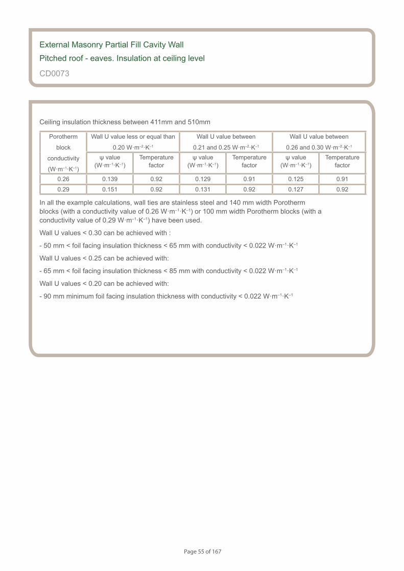
Page 55 of 167
CD0073
Ceiling insulation thickness between 411mm and 510mm
Porotherm
block
conductivity
(W·m–1·K–1)
Wall U value less or equal than
0.20 W·m–2·K–1
Wall U value between
0.21 and 0.25 W·m–2·K–1
Wall U value between
0.26 and 0.30 W·m–2·K–1
ψ value (W·m–1·K–1)
Temperaturefactor
ψ value (W·m–1·K–1)
Temperaturefactor
ψ value (W·m–1·K–1)
Temperaturefactor
0.26 0.139 0.92 0.129 0.91 0.125 0.91
0.29 0.151 0.92 0.131 0.92 0.127 0.92
In all the example calculations, wall ties are stainless steel and 140 mm width Porotherm blocks (with a conductivity value of 0.26 W·m–1·K–1) or 100 mm width Porotherm blocks (with a conductivity value of 0.29 W·m–1·K–1) have been used.
Wall U values < 0.30 can be achieved with :
- 50 mm < foil facing insulation thickness < 65 mm with conductivity < 0.022 W·m–1·K–1
Wall U values < 0.25 can be achieved with:
- 65 mm < foil facing insulation thickness < 85 mm with conductivity < 0.022 W·m–1·K–1
Wall U values < 0.20 can be achieved with:
- 90 mm minimum foil facing insulation thickness with conductivity < 0.022 W·m–1·K–1
External Masonry Partial Fill Cavity Wall
Pitched roof - eaves. Insulation at ceiling level
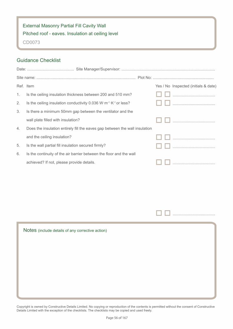
Page 56 of 167
Notes (include details of any corrective action)
CD0073
Guidance Checklist
Date: ........................................... Site Manager/Supervisor: ......................................................................................
Site name: ........................................................................................... Plot No: ........................................................
Ref. Item Yes / No Inspected (initials & date)
1. Is the ceiling insulation thickness between 200 and 510 mm?
2. Is the ceiling insulation conductivity 0.036 W·m-1·K-1 or less?
3. Is there a minimum 50mm gap between the ventilator and the
wall plate filled with insulation?
4. Does the insulation entirely fill the eaves gap between the wall insulation
and the ceiling insulation?
5. Is the wall partial fill insulation secured firmly?
6. Is the continuity of the air barrier between the floor and the wall
achieved? If not, please provide details.
Copyright is owned by Constructive Details Limited. No copying or reproduction of the contents is permitted without the consent of Constructive Details Limited with the exception of the checklists. The checklists may be copied and used freely.
.......................................
.......................................
.......................................
.......................................
.......................................
.......................................
.......................................
External Masonry Partial Fill Cavity Wall
Pitched roof - eaves. Insulation at ceiling level
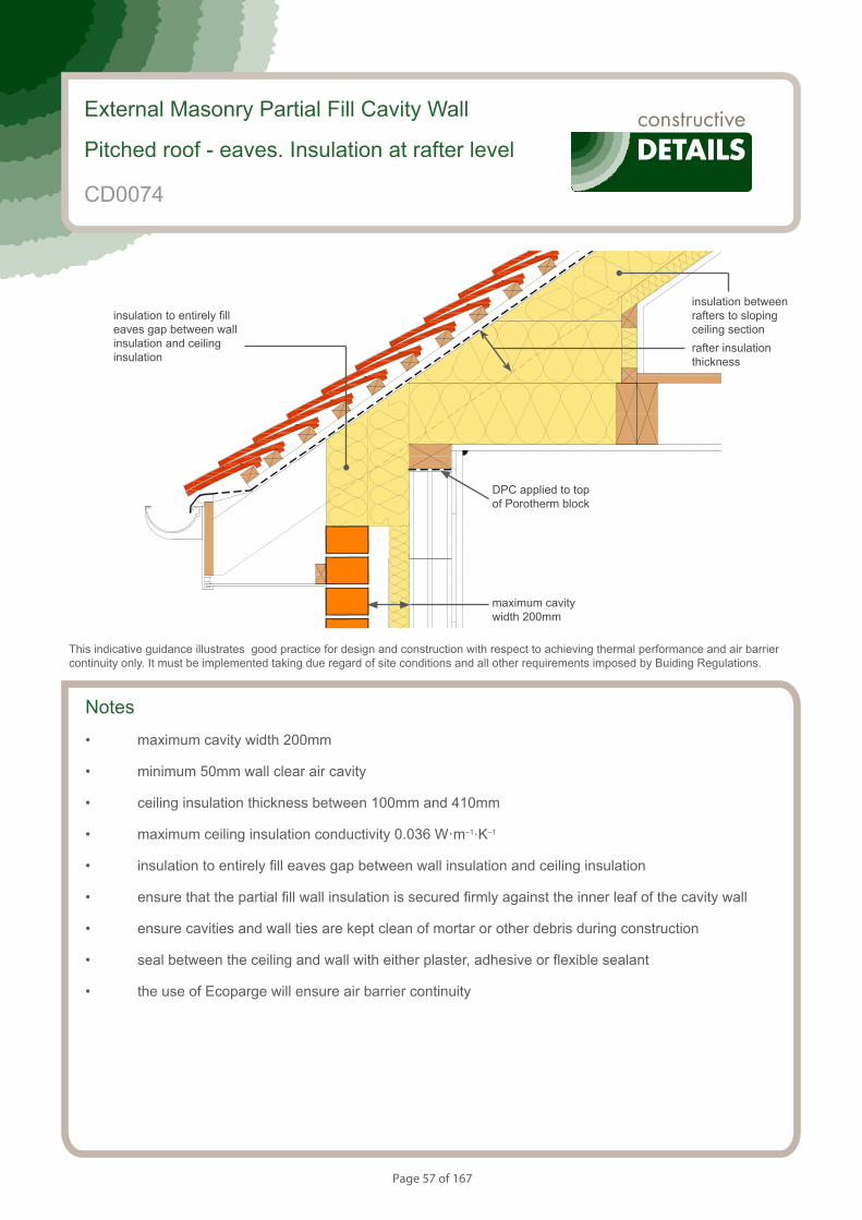
Page 57 of 167
S154083_CD16-1
Pitched roof. Eaves - Insulation at rafter level - Unventilated rafter void
External Masonry Partial Fill Cavity Wall
Pitched roof - eaves. Insulation at rafter level
This indicative guidance illustrates good practice for design and construction with respect to achieving thermal performance and air barrier continuity only. It must be implemented taking due regard of site conditions and all other requirements imposed by Buiding Regulations.
maximum cavity width 200mm
insulation between rafters to sloping ceiling section
insulation to entirely fill eaves gap between wall insulation and ceiling insulation
Notes
• maximum cavity width 200mm
• minimum 50mm wall clear air cavity
• ceiling insulation thickness between 100mm and 410mm
• maximum ceiling insulation conductivity 0.036 W·m–1·K–1
• insulation to entirely fill eaves gap between wall insulation and ceiling insulation
• ensure that the partial fill wall insulation is secured firmly against the inner leaf of the cavity wall
• ensure cavities and wall ties are kept clean of mortar or other debris during construction
• seal between the ceiling and wall with either plaster, adhesive or flexible sealant
• the use of Ecoparge will ensure air barrier continuity
rafter insulation thickness
CD0074
DPC applied to top of Porotherm block
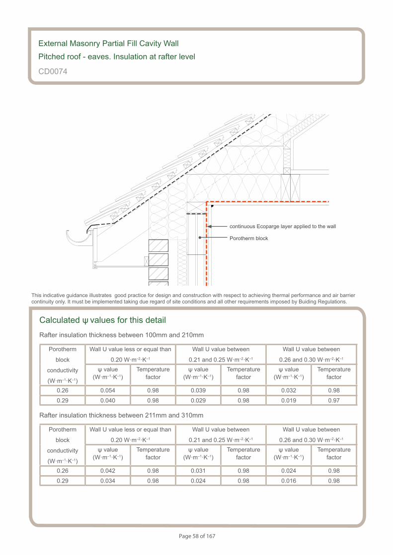
Page 58 of 167
S154083_CD16-2
Pitched roof. Eaves - Insulation at rafter level - Unventilated rafter void
Calculated ψ values for this detail
Rafter insulation thickness between 100mm and 210mm
Porotherm
block
conductivity
(W·m–1·K–1)
Wall U value less or equal than
0.20 W·m–2·K–1
Wall U value between
0.21 and 0.25 W·m–2·K–1
Wall U value between
0.26 and 0.30 W·m–2·K–1
ψ value (W·m–1·K–1)
Temperaturefactor
ψ value (W·m–1·K–1)
Temperaturefactor
ψ value (W·m–1·K–1)
Temperaturefactor
0.26 0.054 0.98 0.039 0.98 0.032 0.98
0.29 0.040 0.98 0.029 0.98 0.019 0.97
Rafter insulation thickness between 211mm and 310mm
Porotherm
block
conductivity
(W·m–1·K–1)
Wall U value less or equal than
0.20 W·m–2·K–1
Wall U value between
0.21 and 0.25 W·m–2·K–1
Wall U value between
0.26 and 0.30 W·m–2·K–1
ψ value (W·m–1·K–1)
Temperaturefactor
ψ value (W·m–1·K–1)
Temperaturefactor
ψ value (W·m–1·K–1)
Temperaturefactor
0.26 0.042 0.98 0.031 0.98 0.024 0.98
0.29 0.034 0.98 0.024 0.98 0.016 0.98
External Masonry Partial Fill Cavity Wall
Pitched roof - eaves. Insulation at rafter level
CD0074
This indicative guidance illustrates good practice for design and construction with respect to achieving thermal performance and air barrier continuity only. It must be implemented taking due regard of site conditions and all other requirements imposed by Buiding Regulations.
Porotherm block
continuous Ecoparge layer applied to the wall
Page 59 of 167
CD0074
Rafter insulation thickness between 311mm and 410mm
Porotherm
block
conductivity
(W·m–1·K–1)
Wall U value less or equal than
0.20 W·m–2·K–1
Wall U value between
0.21 and 0.25 W·m–2·K–1
Wall U value between
0.26 and 0.30 W·m–2·K–1
ψ value (W·m–1·K–1)
Temperaturefactor
ψ value (W·m–1·K–1)
Temperaturefactor
ψ value (W·m–1·K–1)
Temperaturefactor
0.26 0.038 0.98 0.028 0.98 0.022 0.98
0.29 0.032 0.98 0.024 0.98 0.016 0.98
In all the example calculations, wall ties are stainless steel and 140 mm width Porotherm blocks (with a conductivity value of 0.26 W·m–1·K–1) or 100 mm width Porotherm blocks (with a conductivity value of 0.29 W·m–1·K–1) have been used.
Wall U values < 0.30 can be achieved with :
- 50 mm < foil facing insulation thickness < 65 mm with conductivity < 0.022 W·m–1·K–1
Wall U values < 0.25 can be achieved with:
- 65 mm < foil facing insulation thickness < 85 mm with conductivity < 0.022 W·m–1·K–1
Wall U values < 0.20 can be achieved with:
- 90 mm minimum foil facing insulation thickness with conductivity < 0.022 W·m–1·K–1
External Masonry Partial Fill Cavity Wall
Pitched roof - eaves. Insulation at rafter level
Page 60 of 167
Notes (include details of any corrective action)
CD0074
Guidance Checklist
Date: ........................................... Site Manager/Supervisor: ......................................................................................
Site name: ........................................................................................... Plot No: ........................................................
Ref. Item Yes / No Inspected (initials & date)
1. Is the ceiling insulation thickness between 100 and 410 mm?
2. Is the ceiling insulation conductivity 0.036 W·m-1·K-1 or less?
3. Is there a minimum 50mm gap between the ventilator and the
wall plate filled with insulation?
4. Does the insulation entirely fill the eaves gap between the wall insulation
and the ceiling insulation?
5. Is the wall partial fill insulation secured firmly?
6. Is the continuity of the air barrier between the floor and the wall
achieved? If not, please provide details.
Copyright is owned by Constructive Details Limited. No copying or reproduction of the contents is permitted without the consent of Constructive Details Limited with the exception of the checklists. The checklists may be copied and used freely.
.......................................
.......................................
.......................................
.......................................
.......................................
.......................................
External Masonry Partial Fill Cavity Wall
Pitched roof - eaves. Insulation at rafter level
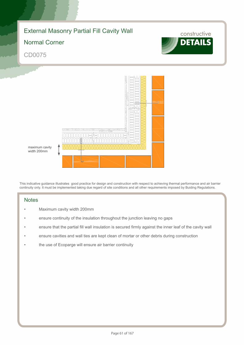
Page 61 of 167
Notes
• Maximum cavity width 200mm
• ensure continuity of the insulation throughout the junction leaving no gaps
• ensure that the partial fill wall insulation is secured firmly against the inner leaf of the cavity wall
• ensure cavities and wall ties are kept clean of mortar or other debris during construction
• the use of Ecoparge will ensure air barrier continuity
External Masonry Partial Fill Cavity Wall
Normal Corner
CD0075
This indicative guidance illustrates good practice for design and construction with respect to achieving thermal performance and air barrier continuity only. It must be implemented taking due regard of site conditions and all other requirements imposed by Buiding Regulations.
maximum cavity width 200mm
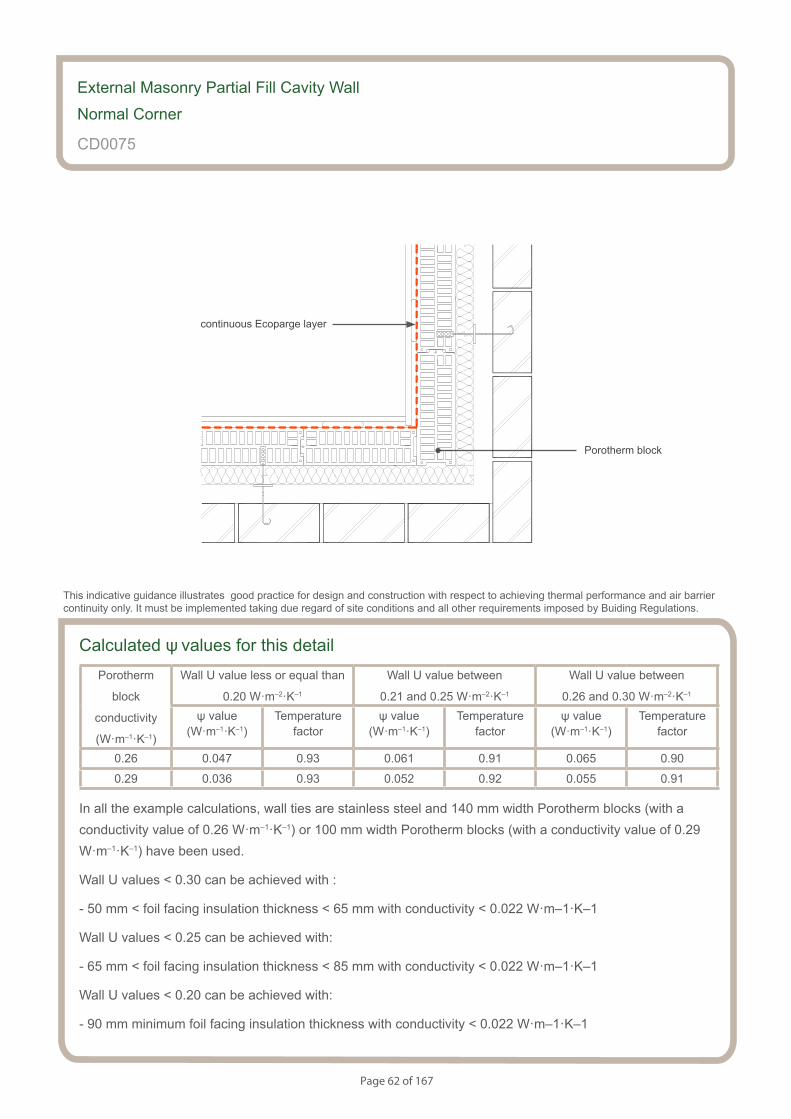
Page 62 of 167
Calculated ψ values for this detailPorotherm
block
conductivity
(W·m–1·K–1)
Wall U value less or equal than
0.20 W·m–2·K–1
Wall U value between
0.21 and 0.25 W·m–2·K–1
Wall U value between
0.26 and 0.30 W·m–2·K–1
ψ value (W·m–1·K–1)
Temperaturefactor
ψ value (W·m–1·K–1)
Temperaturefactor
ψ value (W·m–1·K–1)
Temperaturefactor
0.26 0.047 0.93 0.061 0.91 0.065 0.90
0.29 0.036 0.93 0.052 0.92 0.055 0.91
In all the example calculations, wall ties are stainless steel and 140 mm width Porotherm blocks (with a conductivity value of 0.26 W·m–1·K–1) or 100 mm width Porotherm blocks (with a conductivity value of 0.29 W·m–1·K–1) have been used.
Wall U values < 0.30 can be achieved with :
- 50 mm < foil facing insulation thickness < 65 mm with conductivity < 0.022 W·m–1·K–1
Wall U values < 0.25 can be achieved with:
- 65 mm < foil facing insulation thickness < 85 mm with conductivity < 0.022 W·m–1·K–1
Wall U values < 0.20 can be achieved with:
- 90 mm minimum foil facing insulation thickness with conductivity < 0.022 W·m–1·K–1
External Masonry Partial Fill Cavity Wall
Normal Corner
CD0075
This indicative guidance illustrates good practice for design and construction with respect to achieving thermal performance and air barrier continuity only. It must be implemented taking due regard of site conditions and all other requirements imposed by Buiding Regulations.
continuous Ecoparge layer
Porotherm block
Page 63 of 167
Notes (include details of any corrective action)
External Masonry Partial Fill Cavity Wall
Normal Corner
CD0075
Guidance Checklist
Date: ........................................... Site Manager/Supervisor: ......................................................................................
Site name: ........................................................................................... Plot No: ........................................................
Ref. Item Yes / No Inspected (initials & date)
1. Is there a maximum cavity width 200mm?
2. Does the insulation continue throughout the junction leaving no gaps?
3. Is the partial fill wall insulation secured firmly against the inner leaf
of the cavity wall?
4. Are cavities and wall ties are kept clean of mortar or other debris
during construction?
5. Is Ecoparge applied to ensure air barrier continuity?
Copyright is owned by Constructive Details Limited. No copying or reproduction of the contents is permitted without the consent of Constructive Details Limited with the exception of the checklists. The checklists may be copied and used freely.
.......................................
.......................................
.......................................
.......................................
.......................................
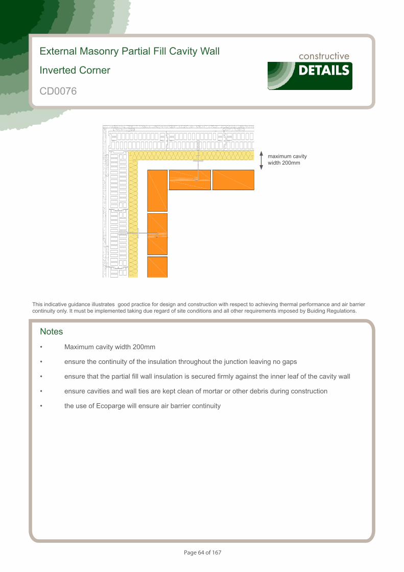
Page 64 of 167
Notes
• Maximum cavity width 200mm
• ensure the continuity of the insulation throughout the junction leaving no gaps
• ensure that the partial fill wall insulation is secured firmly against the inner leaf of the cavity wall
• ensure cavities and wall ties are kept clean of mortar or other debris during construction
• the use of Ecoparge will ensure air barrier continuity
External Masonry Partial Fill Cavity Wall
Inverted Corner
This indicative guidance illustrates good practice for design and construction with respect to achieving thermal performance and air barrier continuity only. It must be implemented taking due regard of site conditions and all other requirements imposed by Buiding Regulations.
maximum cavity width 200mm
CD0076
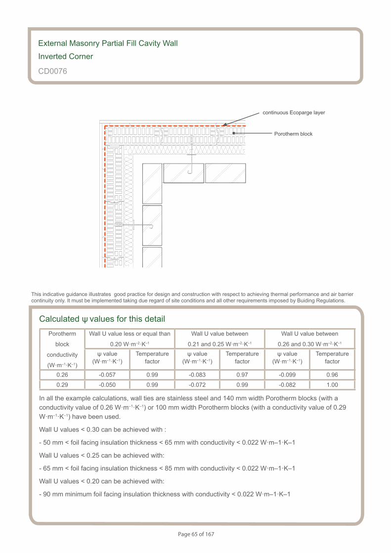
Page 65 of 167
Calculated ψ values for this detailPorotherm
block
conductivity
(W·m–1·K–1)
Wall U value less or equal than
0.20 W·m–2·K–1
Wall U value between
0.21 and 0.25 W·m–2·K–1
Wall U value between
0.26 and 0.30 W·m–2·K–1
ψ value (W·m–1·K–1)
Temperaturefactor
ψ value (W·m–1·K–1)
Temperaturefactor
ψ value (W·m–1·K–1)
Temperaturefactor
0.26 -0.057 0.99 -0.083 0.97 -0.099 0.96
0.29 -0.050 0.99 -0.072 0.99 -0.082 1.00
In all the example calculations, wall ties are stainless steel and 140 mm width Porotherm blocks (with a conductivity value of 0.26 W·m–1·K–1) or 100 mm width Porotherm blocks (with a conductivity value of 0.29 W·m–1·K–1) have been used.
Wall U values < 0.30 can be achieved with :
- 50 mm < foil facing insulation thickness < 65 mm with conductivity < 0.022 W·m–1·K–1
Wall U values < 0.25 can be achieved with:
- 65 mm < foil facing insulation thickness < 85 mm with conductivity < 0.022 W·m–1·K–1
Wall U values < 0.20 can be achieved with:
- 90 mm minimum foil facing insulation thickness with conductivity < 0.022 W·m–1·K–1
External Masonry Partial Fill Cavity Wall
Inverted Corner
CD0076
This indicative guidance illustrates good practice for design and construction with respect to achieving thermal performance and air barrier continuity only. It must be implemented taking due regard of site conditions and all other requirements imposed by Buiding Regulations.
continuous Ecoparge layer
Porotherm block
Page 66 of 167
Notes (include details of any corrective action)
CD0076
Guidance Checklist
Date: ........................................... Site Manager/Supervisor: ......................................................................................
Site name: ........................................................................................... Plot No: ........................................................
Ref. Item Yes / No Inspected (initials & date)
1. Is the continuity of insulation throughout the junction achieved?
2. Is the partial fill insulation secured firmly?
3. Is the continuity of the air barrier achieved? If not, please provide
details.
Copyright is owned by Constructive Details Limited. No copying or reproduction of the contents is permitted without the consent of Constructive Details Limited with the exception of the checklists. The checklists may be copied and used freely.
.......................................
.......................................
.......................................
.......................................
.......................................
.......................................
.......................................
.......................................
.......................................
.......................................
.......................................
.......................................
External Masonry Partial Fill Cavity Wall
Inverted Corner
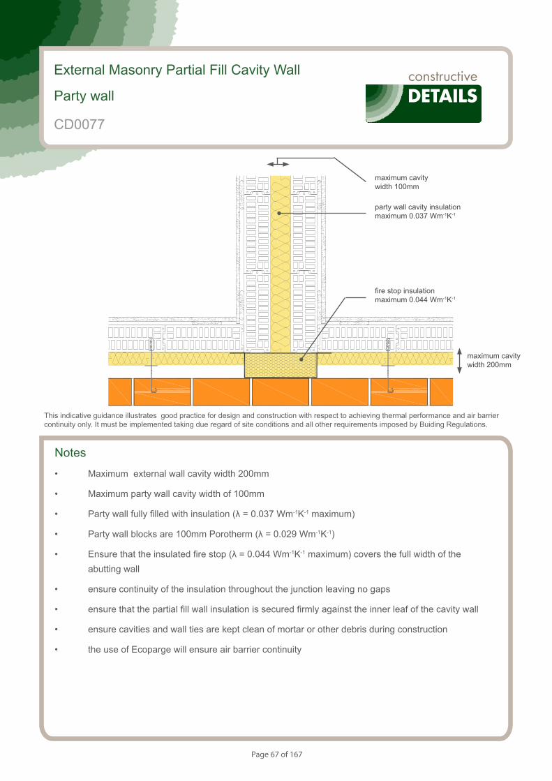
Page 67 of 167
Notes
• Maximum external wall cavity width 200mm
• Maximum party wall cavity width of 100mm
• Party wall fully filled with insulation (λ = 0.037 Wm-1K-1 maximum)
• Party wall blocks are 100mm Porotherm (λ = 0.029 Wm-1K-1)
• Ensure that the insulated fire stop (λ = 0.044 Wm-1K-1 maximum) covers the full width of the abutting wall
• ensure continuity of the insulation throughout the junction leaving no gaps
• ensure that the partial fill wall insulation is secured firmly against the inner leaf of the cavity wall
• ensure cavities and wall ties are kept clean of mortar or other debris during construction
• the use of Ecoparge will ensure air barrier continuity
External Masonry Partial Fill Cavity Wall
Party wall
This indicative guidance illustrates good practice for design and construction with respect to achieving thermal performance and air barrier continuity only. It must be implemented taking due regard of site conditions and all other requirements imposed by Buiding Regulations.
maximum cavity width 200mm
maximum cavity width 100mm
party wall cavity insulation maximum 0.037 Wm-1K-1
fire stop insulation maximum 0.044 Wm-1K-1
CD0077
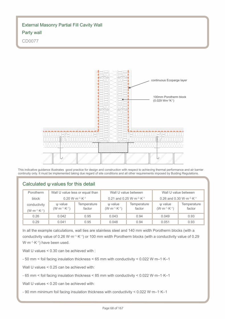
Page 68 of 167
Calculated ψ values for this detailPorotherm
block
conductivity
(W·m–1·K–1)
Wall U value less or equal than
0.20 W·m–2·K–1
Wall U value between
0.21 and 0.25 W·m–2·K–1
Wall U value between
0.26 and 0.30 W·m–2·K–1
ψ value (W·m–1·K–1)
Temperaturefactor
ψ value (W·m–1·K–1)
Temperaturefactor
ψ value (W·m–1·K–1)
Temperaturefactor
0.26 0.042 0.95 0.043 0.94 0.049 0.93
0.29 0.041 0.95 0.048 0.94 0.051 0.93
In all the example calculations, wall ties are stainless steel and 140 mm width Porotherm blocks (with a conductivity value of 0.26 W·m–1·K–1) or 100 mm width Porotherm blocks (with a conductivity value of 0.29 W·m–1·K–1) have been used.
Wall U values < 0.30 can be achieved with :
- 50 mm < foil facing insulation thickness < 65 mm with conductivity < 0.022 W·m–1·K–1
Wall U values < 0.25 can be achieved with:
- 65 mm < foil facing insulation thickness < 85 mm with conductivity < 0.022 W·m–1·K–1
Wall U values < 0.20 can be achieved with:
- 90 mm minimum foil facing insulation thickness with conductivity < 0.022 W·m–1·K–1
External Masonry Partial Fill Cavity Wall
Party wall
CD0077
This indicative guidance illustrates good practice for design and construction with respect to achieving thermal performance and air barrier continuity only. It must be implemented taking due regard of site conditions and all other requirements imposed by Buiding Regulations.
continuous Ecoparge layer
100mm Porotherm block (0.029 Wm-1K-1)
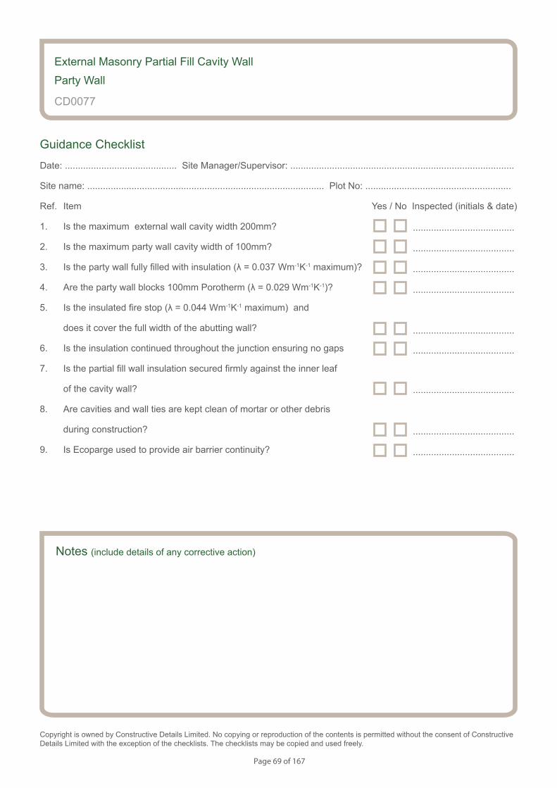
Page 69 of 167
Notes (include details of any corrective action)
External Masonry Partial Fill Cavity Wall
Party Wall
CD0077
Guidance Checklist
Date: ........................................... Site Manager/Supervisor: ......................................................................................
Site name: ........................................................................................... Plot No: ........................................................
Ref. Item Yes / No Inspected (initials & date)
1. Is the maximum external wall cavity width 200mm?
2. Is the maximum party wall cavity width of 100mm?
3. Is the party wall fully filled with insulation (λ = 0.037 Wm-1K-1 maximum)?
4. Are the party wall blocks 100mm Porotherm (λ = 0.029 Wm-1K-1)?
5. Is the insulated fire stop (λ = 0.044 Wm-1K-1 maximum) and
does it cover the full width of the abutting wall?
6. Is the insulation continued throughout the junction ensuring no gaps
7. Is the partial fill wall insulation secured firmly against the inner leaf
of the cavity wall?
8. Are cavities and wall ties are kept clean of mortar or other debris
during construction?
9. Is Ecoparge used to provide air barrier continuity?
Copyright is owned by Constructive Details Limited. No copying or reproduction of the contents is permitted without the consent of Constructive Details Limited with the exception of the checklists. The checklists may be copied and used freely.
.......................................
.......................................
.......................................
.......................................
.......................................
.......................................
.......................................
.......................................
.......................................
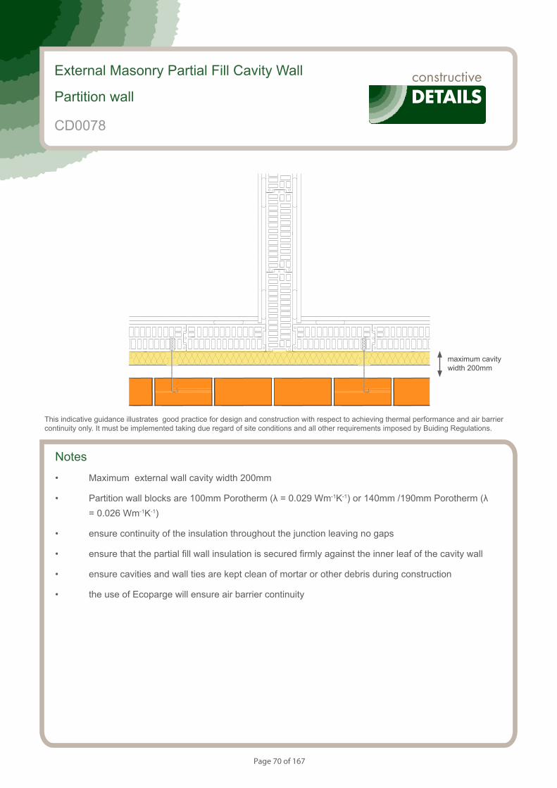
Page 70 of 167
S153084_CD20-1
Partition wall within a dwelling
Notes
• Maximum external wall cavity width 200mm
• Partition wall blocks are 100mm Porotherm (λ = 0.029 Wm-1K-1) or 140mm /190mm Porotherm (λ = 0.026 Wm-1K-1)
• ensure continuity of the insulation throughout the junction leaving no gaps
• ensure that the partial fill wall insulation is secured firmly against the inner leaf of the cavity wall
• ensure cavities and wall ties are kept clean of mortar or other debris during construction
• the use of Ecoparge will ensure air barrier continuity
External Masonry Partial Fill Cavity Wall
Partition wall
This indicative guidance illustrates good practice for design and construction with respect to achieving thermal performance and air barrier continuity only. It must be implemented taking due regard of site conditions and all other requirements imposed by Buiding Regulations.
maximum cavity width 200mm
CD0078
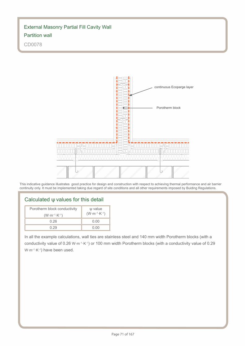
Page 71 of 167
Partition wall within a dwelling
S153084_CD20-2
Calculated ψ values for this detailPorotherm block conductivity
(W·m–1·K–1)
ψ value (W·m–1·K–1)
0.26 0.00
0.29 0.00
In all the example calculations, wall ties are stainless steel and 140 mm width Porotherm blocks (with a conductivity value of 0.26 W·m–1·K–1) or 100 mm width Porotherm blocks (with a conductivity value of 0.29 W·m–1·K–1) have been used.
External Masonry Partial Fill Cavity Wall
Partition wall
CD0078
This indicative guidance illustrates good practice for design and construction with respect to achieving thermal performance and air barrier continuity only. It must be implemented taking due regard of site conditions and all other requirements imposed by Buiding Regulations.
continuous Ecoparge layer
Porotherm block
Page 72 of 167
Notes (include details of any corrective action)
CD0078
Guidance Checklist
Date: ........................................... Site Manager/Supervisor: ......................................................................................
Site name: ........................................................................................... Plot No: ........................................................
Ref. Item Yes / No Inspected (initials & date)
1. Is the partition wall formed of Porotherm blocks?
2. Is the continuity if insulation throughout the junction achieved?
3. Is the partial fill insulation secured firmly?
4. Is the continuity of the air barrier achieved? If not, please provide
details.
Copyright is owned by Constructive Details Limited. No copying or reproduction of the contents is permitted without the consent of Constructive Details Limited with the exception of the checklists. The checklists may be copied and used freely.
.......................................
.......................................
.......................................
.......................................
External Masonry Partial Fill Cavity Wall
Partition wall

Page 73 of 167
Notes
• Perimeter insulation strip with a minimum resistance value of 1 m2·K·W-1 (eg 25 mm of insulation with l= 0.025 W·m-1·K-1) and installed up to floor finish
• Medium density blocks below floor level with a maximum l= 0.47 W·m-1·K-1
• Maximum distance between interior and exterior floor level of 150 mm
• Minimum underfloor cavity height of 200 mm
• Minimum 200 mm overlap of cavity wall insulation from top of the floor beam
• Maximum cavity width 200mm
• Ensure that the full fill insulation is installed correctly between the inner and outer leaf of the cavity wall with no gaps
• Ensure that the full fill wall insulation is suitable for the wall exposure, and is resistant to water penetration
• Ensure that the floor insulation tightly abuts blockwork wall
• Ensure that there is a seal between the wall and floor air barrier with no gaps between the skirting board and the floor. The use of Ecoparge will ensure air barrier continuity of the wall.
S154083_CD21-1
Beam and Block Floor. Insulation Above Slab.
External Masonry Full Fill Cavity WallSuspended beam and block floor. Insulation above slab
CD0079
This indicative guidance illustrates good practice for design and construction with respect to achieving thermal performance and air barrier continuity only. It must be implemented taking due regard of site conditions and all other requirements imposed by Buiding Regulations.
Maximum wall cavity width 200mm
Minimum 200 mm
Maximum 150 mm
Minimum 200 mm
Medium density block maximum l = 0.47 Wm-
Perimeter insulation minimum resistance value of 1 m2KW-1
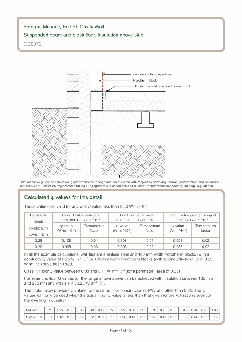
Page 74 of 167
S154083_CD21-2
Beam and Block Floor. Insulation Above Slab.
Calculated ψ values for this detail
These values are valid for any wall U value less than 0.30 W·m–2·K–1
Porotherm
block
conductivity
(W·m–1·K–1)
Floor U value between 0.08 and 0.11 W·m–2·K–1
Floor U value between 0.12 and 0.19 W·m–2·K–1
Floor U value greater or equal than 0.20 W·m–2·K–1
ψ value (W·m–1·K–1)
Temperaturefactor
ψ value (W·m–1·K–1)
Temperaturefactor
ψ value (W·m–1·K–1)
Temperaturefactor
0.26 0.108 0.91 0.108 0.91 0.096 0.92
0.29 0.095 0.93 0.093 0.92 0.087 0.92
In all the example calculations, wall ties are stainless steel and 140 mm width Porotherm blocks (with a conductivity value of 0.26 W·m–1·K–1) or 100 mm width Porotherm blocks (with a conductivity value of 0.29 W·m–1·K–1) have been used.
Case 1: Floor U value between 0.08 and 0.11 W·m–1·K–1 (for a perimeter / area of 0.25)
For example, floor U values for the range shown above can be achieved with insulation between 135 mm and 205 mm and with a l < 0.023 W·m–1·K–1.
The table below provides U values for the same floor construction or P/A ratio other than 0.25. The ψ values can only be used when the actual floor U value is less than that given for the P/A ratio relevant to the dwelling in question.
P/A mm-2 0.20 0.25 0.30 0.35 0.40 0.45 0.50 0.55 0.60 0.65 0.70 0.75 0.80 0.85 0.90 0.95 1.00
U (W·m–1·K–1) 0.11 0.12 0.12 0.12 0.12 0.12 0.13 0.13 0.13 0.13 0.13 0.13 0.13 0.13 0.13 0.13 0.13
-
External Masonry Full Fill Cavity Wall
Suspended beam and block floor. Insulation above slab
CD0079
This indicative guidance illustrates good practice for design and construction with respect to achieving thermal performance and air barrier continuity only. It must be implemented taking due regard of site conditions and all other requirements imposed by Buiding Regulations.
continuous Ecoparge layer
Porotherm block
Continuous seal between floor and wall

Page 75 of 167
Case 2: Floor U value between 0.12 and 0.19 W·m–1·K–1 (for a perimeter / area of 0.25)
For example, floor U values for the range shown above can be achieved with insulation between 60 mm and 120 mm and with a l < 0.023 W·m–1·K–1.
The table below provides U values for the same floor construction or P/A ratio other than 0.25. The ψ values can only be used when the actual floor U value is less than that given for the P/A ratio relevant to the dwelling in question.
P/A mm-2 0.20 0.25 0.30 0.35 0.40 0.45 0.50 0.55 0.60 0.65 0.70 0.75 0.80 0.85 0.90 0.95 1.00
U (W·m–1·K–1) 0.18 0.19 0.19 0.20 0.21 0.21 0.22 0.22 0.23 0.23 0.23 0.23 0.23 0.23 0.24 0.24 0.24
Case 3: Floor U value > 0.20 W·m–1·K–1 (for a perimeter / area of 0.25)
For example, floor U values for the range shown above can be achieved with 50 mm insulation with a l < 0.023 W·m–1·K–1.
The table below provides U values for the same floor construction or P/A ratio other than 0.25. The ψ values can only be used when the actual floor U value is greater than that given for the P/A ratio relevant to the dwelling in question.
P/A mm-2 0.20 0.25 0.30 0.35 0.40 0.45 0.50 0.55 0.60 0.65 0.70 0.75 0.80 0.85 0.90 0.95 1.00
U (W·m–1·K–1) 0.19 0.20 0.22 0.22 0.23 0.24 0.24 0.25 0.25 0.25 0.26 0.26 0.26 0.26 0.27 0.27 0.27
Note: U values 0.26 and above are above the limit for the floor U value according to The Building Regulations 2013 (England and Wales) (As amended).
In all the example calculations, wall ties are stainless steel and 140 mm width Porotherm blocks (with a conductivity value of 0.26 W·m–1·K–1) or 100 mm width Porotherm blocks (with a conductivity value of 0.29 W·m–1·K–1) have been used.
Wall U values less or equal than 0.30 W·m–2·K–1 can be achieved with:
- 100 mm < insulation thickness < 120 mm with conductivity < 0.036 W·m–1·K–1
Wall U values less or equal than 0.25 W·m–2·K–1 can be achieved with:
- 125 mm < insulation thickness < 150 mm with conductivity < 0.036 W·m–1·K–1
Wall U values less or equal than 0.20 W·m–2·K–1 can be achieved with:
- 160 mm minimum insulation thickness with conductivity < 0.036 W·m–1·K–1
Page 76 of 167
Notes (include details of any corrective action)
CD0079
Guidance Checklist
Date: ........................................... Site Manager/Supervisor: ......................................................................................
Site name: ........................................................................................... Plot No: ........................................................
Ref. Item Yes / No Inspected (initials & date)
1. Is the perimeter insulation as specified?
— Minimum resistance value of 1 m2·K·W-1
— Installed up to floor finish
2. Is the full fill insulation continued at least 200 mm below the
underside of the floor insulation?
3. Is the underfloor cavity height of 200 mm or more?
4. Is the maximum distance between interior and exterior floor level
of 150 mm?
5. Is the wall full fill insulation installed correctly with no gaps?
6. Is the wall full fill insulation appropriate for moisture and wall exposure?
7. Is the floor insulation abutting the blockwork wall, leaving no gaps?
8. Is the continuity of the air barrier between the floor and the wall
achieved? If not, please provide details.
Copyright is owned by Constructive Details Limited. No copying or reproduction of the contents is permitted without the consent of Constructive Details Limited with the exception of the checklists. The checklists may be copied and used freely.
.......................................
.......................................
.......................................
.......................................
.......................................
.......................................
.......................................
External Masonry Full Fill Cavity Wall
Suspended beam and block floor. Insulation above slab
.......................................
.......................................

Page 77 of 167
Notes
• Perimeter insulation strip with a minimum resistance value of 1 m2·K·W-1 (eg 25 mm of insulation with l = 0.025 W·m-1·K-1) and installed up to floor finish
• Medium density blocks below floor level with a maximum l = 0.47 W·m-1·K-1
• Thermal block of a minimum height of 65 mm and a maximum l = 0.078 W·m-1·K-1
• Maximum distance between interior and exterior floor level of 150 mm
• Minimum underfloor cavity height of 200 mm
• Minimum 200 mm overlap of cavity wall insulation from top of the floor beam
• Maximum cavity width 200mm
• Ensure that the full fill insulation is installed correctly between the inner and outer leaf of the cavity wall with no gaps
• Ensure that the full fill wall insulation is suitable for the wall exposure, and is resistant to water penetration. Ensure that the floor insulation tightly abuts blockwork wall
• Ensure that there is a seal between the wall and floor air barrier with no gaps between the skirting board and the floor. The use of Ecoparge will ensure air barrier continuity of the wall.
S154083_CD22-1
Beam and Block Floor. Insulation Above Slab. Thermal Block
External Masonry Full Fill Cavity WallSuspended beam and block floor. Insulation above slab. Thermal block
CD0080
This indicative guidance illustrates good practice for design and construction with respect to achieving thermal performance and air barrier continuity only. It must be implemented taking due regard of site conditions and all other requirements imposed by Buiding Regulations.
Maximum wall cavity width 200mm
Minimum 200 mm
Maximum 150 mm
Minimum 200 mm
Medium density block maximum l = 0.47 W·m-1K-1
Perimeter insulation minimum resistance value of 1 m2·K·W-1
65 mm thermal block maximum l = 0.078 W·m-1·K-1
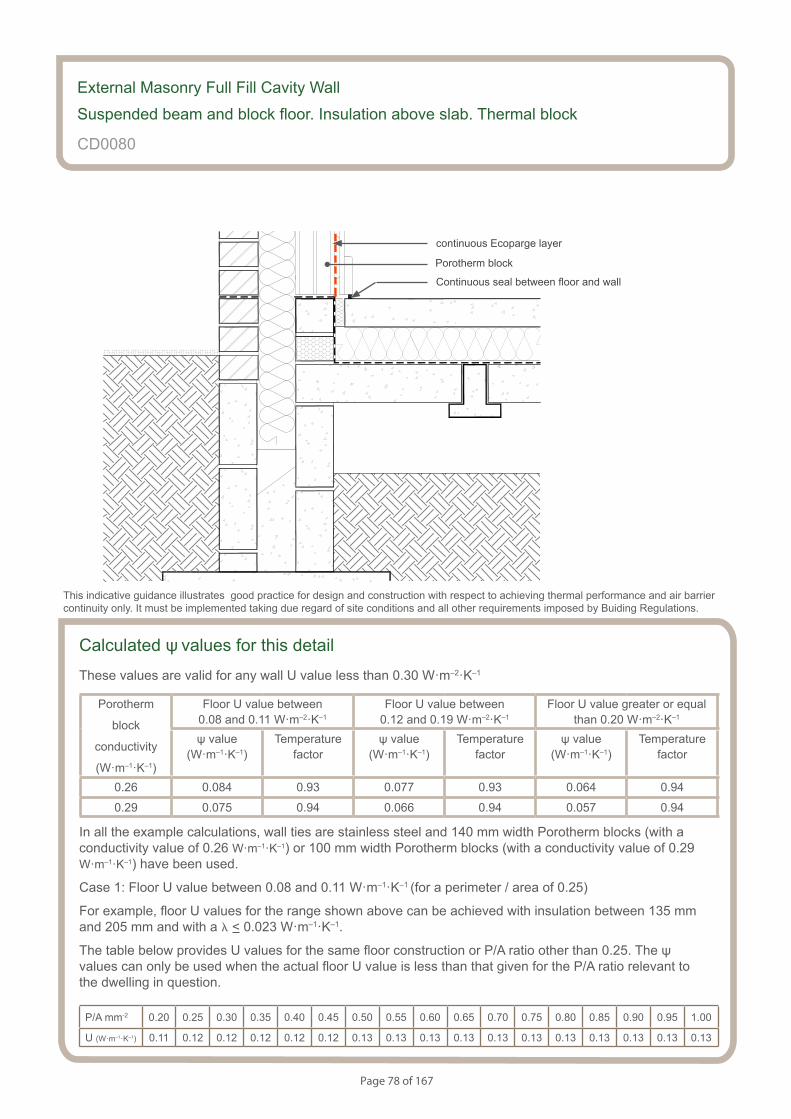
Page 78 of 167
S154083_CD22-2
Beam and Block Floor. Insulation Above Slab. Thermal Block.
Calculated ψ values for this detail
These values are valid for any wall U value less than 0.30 W·m–2·K–1
Porotherm
block
conductivity
(W·m–1·K–1)
Floor U value between 0.08 and 0.11 W·m–2·K–1
Floor U value between 0.12 and 0.19 W·m–2·K–1
Floor U value greater or equal than 0.20 W·m–2·K–1
ψ value (W·m–1·K–1)
Temperaturefactor
ψ value (W·m–1·K–1)
Temperaturefactor
ψ value (W·m–1·K–1)
Temperaturefactor
0.26 0.084 0.93 0.077 0.93 0.064 0.94
0.29 0.075 0.94 0.066 0.94 0.057 0.94
In all the example calculations, wall ties are stainless steel and 140 mm width Porotherm blocks (with a conductivity value of 0.26 W·m–1·K–1) or 100 mm width Porotherm blocks (with a conductivity value of 0.29 W·m–1·K–1) have been used.
Case 1: Floor U value between 0.08 and 0.11 W·m–1·K–1 (for a perimeter / area of 0.25)
For example, floor U values for the range shown above can be achieved with insulation between 135 mm and 205 mm and with a l < 0.023 W·m–1·K–1.
The table below provides U values for the same floor construction or P/A ratio other than 0.25. The ψ values can only be used when the actual floor U value is less than that given for the P/A ratio relevant to the dwelling in question.
P/A mm-2 0.20 0.25 0.30 0.35 0.40 0.45 0.50 0.55 0.60 0.65 0.70 0.75 0.80 0.85 0.90 0.95 1.00
U (W·m–1·K–1) 0.11 0.12 0.12 0.12 0.12 0.12 0.13 0.13 0.13 0.13 0.13 0.13 0.13 0.13 0.13 0.13 0.13
-
External Masonry Full Fill Cavity Wall
Suspended beam and block floor. Insulation above slab. Thermal block
CD0080
This indicative guidance illustrates good practice for design and construction with respect to achieving thermal performance and air barrier continuity only. It must be implemented taking due regard of site conditions and all other requirements imposed by Buiding Regulations.
continuous Ecoparge layer
Porotherm block
Continuous seal between floor and wall
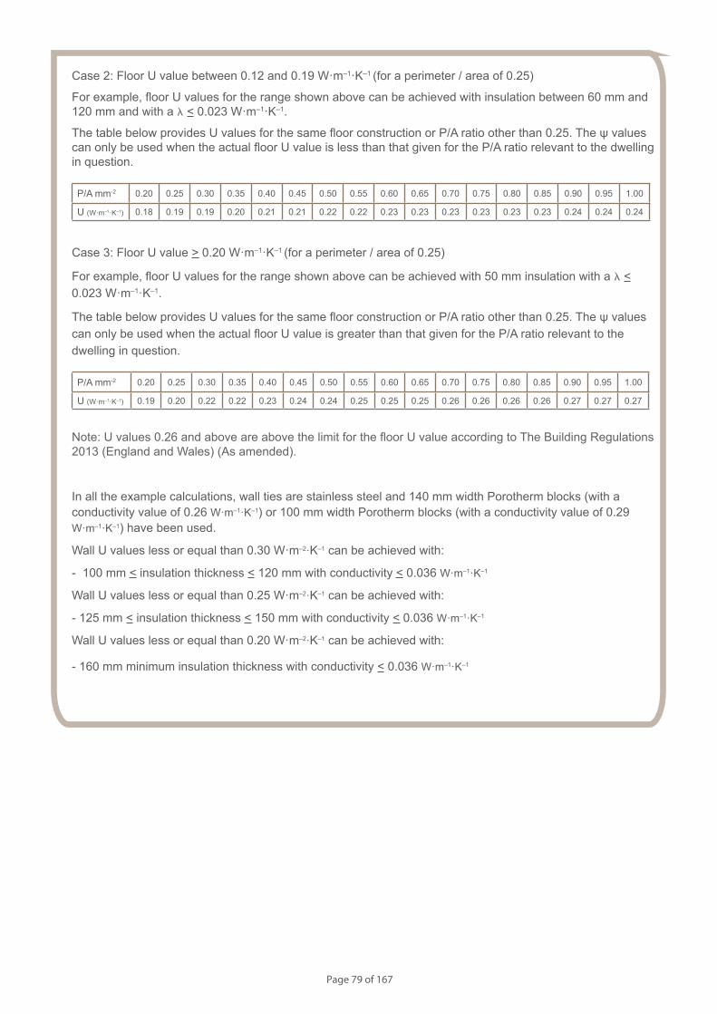
Page 79 of 167
Case 2: Floor U value between 0.12 and 0.19 W·m–1·K–1 (for a perimeter / area of 0.25)
For example, floor U values for the range shown above can be achieved with insulation between 60 mm and 120 mm and with a l < 0.023 W·m–1·K–1.
The table below provides U values for the same floor construction or P/A ratio other than 0.25. The ψ values can only be used when the actual floor U value is less than that given for the P/A ratio relevant to the dwelling in question.
P/A mm-2 0.20 0.25 0.30 0.35 0.40 0.45 0.50 0.55 0.60 0.65 0.70 0.75 0.80 0.85 0.90 0.95 1.00
U (W·m–1·K–1) 0.18 0.19 0.19 0.20 0.21 0.21 0.22 0.22 0.23 0.23 0.23 0.23 0.23 0.23 0.24 0.24 0.24
Case 3: Floor U value > 0.20 W·m–1·K–1 (for a perimeter / area of 0.25)
For example, floor U values for the range shown above can be achieved with 50 mm insulation with a l < 0.023 W·m–1·K–1.
The table below provides U values for the same floor construction or P/A ratio other than 0.25. The ψ values can only be used when the actual floor U value is greater than that given for the P/A ratio relevant to the dwelling in question.
P/A mm-2 0.20 0.25 0.30 0.35 0.40 0.45 0.50 0.55 0.60 0.65 0.70 0.75 0.80 0.85 0.90 0.95 1.00
U (W·m–1·K–1) 0.19 0.20 0.22 0.22 0.23 0.24 0.24 0.25 0.25 0.25 0.26 0.26 0.26 0.26 0.27 0.27 0.27
Note: U values 0.26 and above are above the limit for the floor U value according to The Building Regulations 2013 (England and Wales) (As amended).
In all the example calculations, wall ties are stainless steel and 140 mm width Porotherm blocks (with a conductivity value of 0.26 W·m–1·K–1) or 100 mm width Porotherm blocks (with a conductivity value of 0.29 W·m–1·K–1) have been used.
Wall U values less or equal than 0.30 W·m–2·K–1 can be achieved with:
- 100 mm < insulation thickness < 120 mm with conductivity < 0.036 W·m–1·K–1
Wall U values less or equal than 0.25 W·m–2·K–1 can be achieved with:
- 125 mm < insulation thickness < 150 mm with conductivity < 0.036 W·m–1·K–1
Wall U values less or equal than 0.20 W·m–2·K–1 can be achieved with:
- 160 mm minimum insulation thickness with conductivity < 0.036 W·m–1·K–1
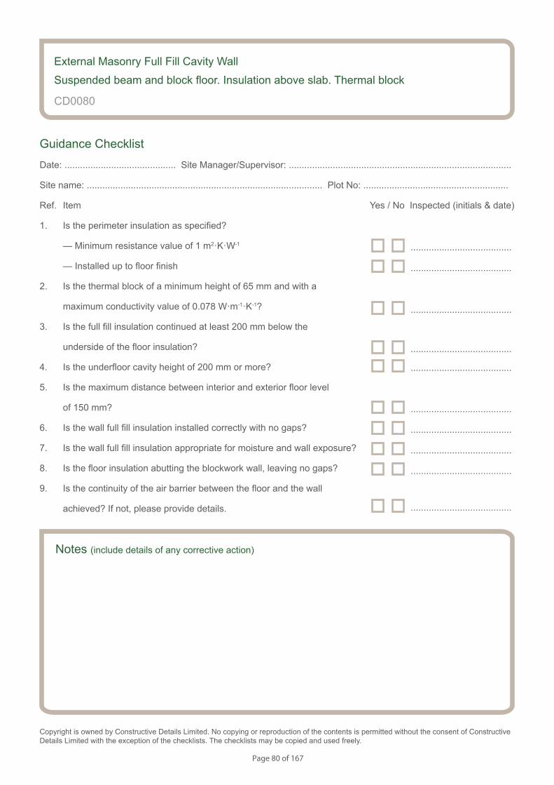
Page 80 of 167
Notes (include details of any corrective action)
CD0080
Guidance Checklist
Date: ........................................... Site Manager/Supervisor: ......................................................................................
Site name: ........................................................................................... Plot No: ........................................................
Ref. Item Yes / No Inspected (initials & date)
1. Is the perimeter insulation as specified?
— Minimum resistance value of 1 m2·K·W-1
— Installed up to floor finish
2. Is the thermal block of a minimum height of 65 mm and with a
maximum conductivity value of 0.078 W·m-1·K-1?
3. Is the full fill insulation continued at least 200 mm below the
underside of the floor insulation?
4. Is the underfloor cavity height of 200 mm or more?
5. Is the maximum distance between interior and exterior floor level
of 150 mm?
6. Is the wall full fill insulation installed correctly with no gaps?
7. Is the wall full fill insulation appropriate for moisture and wall exposure?
8. Is the floor insulation abutting the blockwork wall, leaving no gaps?
9. Is the continuity of the air barrier between the floor and the wall
achieved? If not, please provide details.
Copyright is owned by Constructive Details Limited. No copying or reproduction of the contents is permitted without the consent of Constructive Details Limited with the exception of the checklists. The checklists may be copied and used freely.
.......................................
.......................................
.......................................
.......................................
.......................................
.......................................
.......................................
.......................................
.......................................
External Masonry Full Fill Cavity Wall
Suspended beam and block floor. Insulation above slab. Thermal block
.......................................
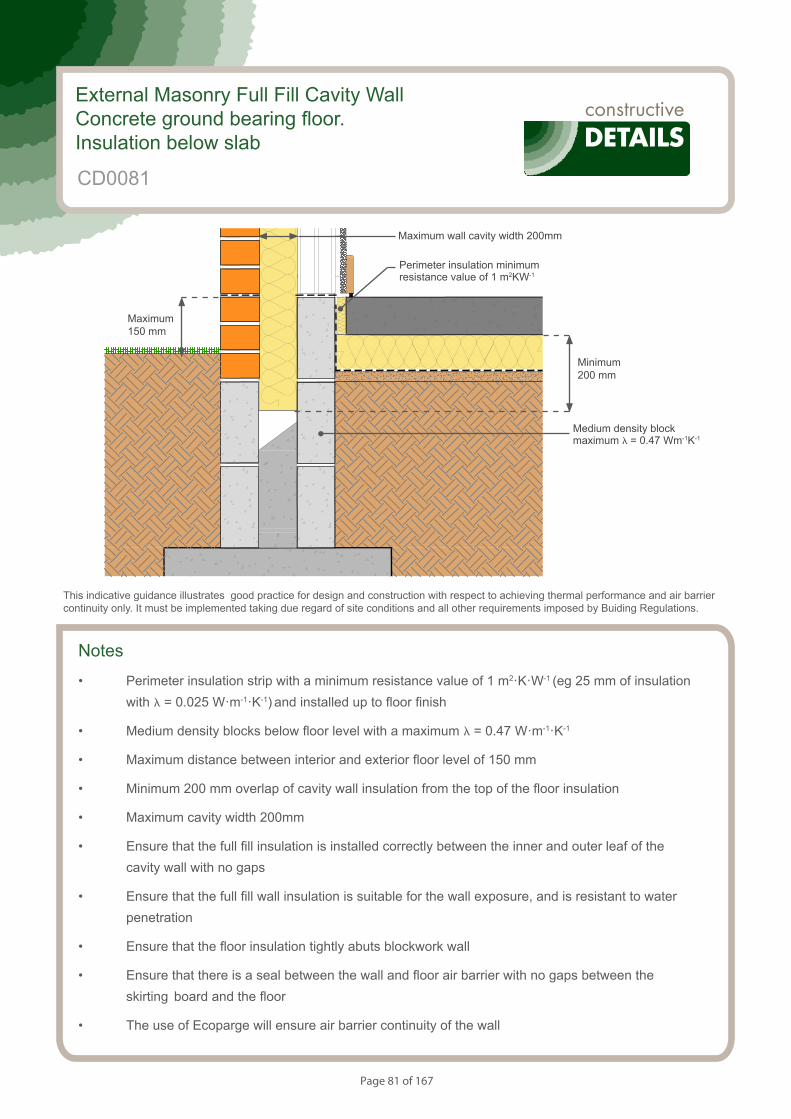
Page 81 of 167
Notes
• Perimeter insulation strip with a minimum resistance value of 1 m2·K·W-1 (eg 25 mm of insulation with l = 0.025 W·m-1·K-1) and installed up to floor finish
• Medium density blocks below floor level with a maximum l = 0.47 W·m-1·K-1
• Maximum distance between interior and exterior floor level of 150 mm
• Minimum 200 mm overlap of cavity wall insulation from the top of the floor insulation
• Maximum cavity width 200mm
• Ensure that the full fill insulation is installed correctly between the inner and outer leaf of the cavity wall with no gaps
• Ensure that the full fill wall insulation is suitable for the wall exposure, and is resistant to water penetration
• Ensure that the floor insulation tightly abuts blockwork wall
• Ensure that there is a seal between the wall and floor air barrier with no gaps between the skirting board and the floor
• The use of Ecoparge will ensure air barrier continuity of the wall
S049495_CD23-1
Concrete Ground Bearing Floor. Insulation Below Slab.
External Masonry Full Fill Cavity WallConcrete ground bearing floor. Insulation below slab
CD0081
This indicative guidance illustrates good practice for design and construction with respect to achieving thermal performance and air barrier continuity only. It must be implemented taking due regard of site conditions and all other requirements imposed by Buiding Regulations.
Maximum wall cavity width 200mm
Minimum 200 mm
Medium density block maximum l = 0.47 Wm-1K-1
Perimeter insulation minimum resistance value of 1 m2KW-1
Maximum 150 mm
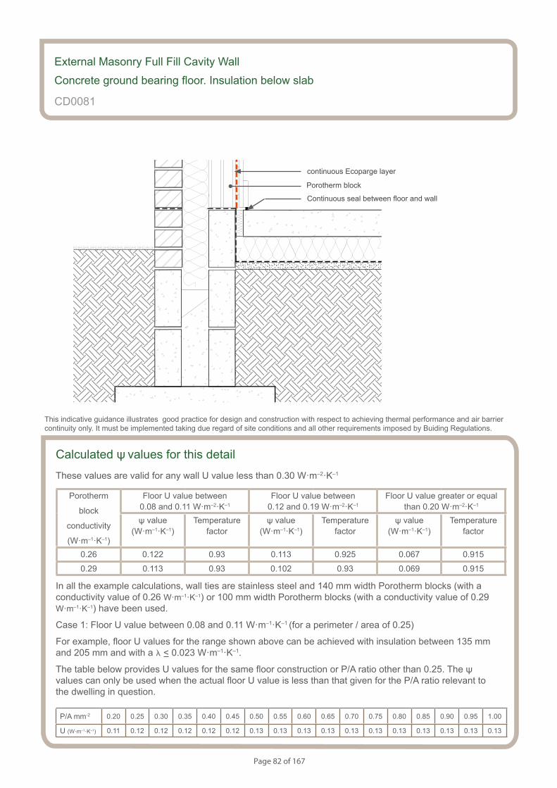
Page 82 of 167
S049495_CD23-2
Concrete Ground Bearing Floor. Insulation Below Slab.
Calculated ψ values for this detail
These values are valid for any wall U value less than 0.30 W·m–2·K–1
Porotherm
block
conductivity
(W·m–1·K–1)
Floor U value between 0.08 and 0.11 W·m–2·K–1
Floor U value between 0.12 and 0.19 W·m–2·K–1
Floor U value greater or equal than 0.20 W·m–2·K–1
ψ value (W·m–1·K–1)
Temperaturefactor
ψ value (W·m–1·K–1)
Temperaturefactor
ψ value (W·m–1·K–1)
Temperaturefactor
0.26 0.122 0.93 0.113 0.925 0.067 0.915
0.29 0.113 0.93 0.102 0.93 0.069 0.915
In all the example calculations, wall ties are stainless steel and 140 mm width Porotherm blocks (with a conductivity value of 0.26 W·m–1·K–1) or 100 mm width Porotherm blocks (with a conductivity value of 0.29 W·m–1·K–1) have been used.
Case 1: Floor U value between 0.08 and 0.11 W·m–1·K–1 (for a perimeter / area of 0.25)
For example, floor U values for the range shown above can be achieved with insulation between 135 mm and 205 mm and with a l < 0.023 W·m–1·K–1.
The table below provides U values for the same floor construction or P/A ratio other than 0.25. The ψ values can only be used when the actual floor U value is less than that given for the P/A ratio relevant to the dwelling in question.
P/A mm-2 0.20 0.25 0.30 0.35 0.40 0.45 0.50 0.55 0.60 0.65 0.70 0.75 0.80 0.85 0.90 0.95 1.00
U (W·m–1·K–1) 0.11 0.12 0.12 0.12 0.12 0.12 0.13 0.13 0.13 0.13 0.13 0.13 0.13 0.13 0.13 0.13 0.13
External Masonry Full Fill Cavity Wall
Concrete ground bearing floor. Insulation below slab
CD0081
This indicative guidance illustrates good practice for design and construction with respect to achieving thermal performance and air barrier continuity only. It must be implemented taking due regard of site conditions and all other requirements imposed by Buiding Regulations.
continuous Ecoparge layer
Porotherm block
Continuous seal between floor and wall
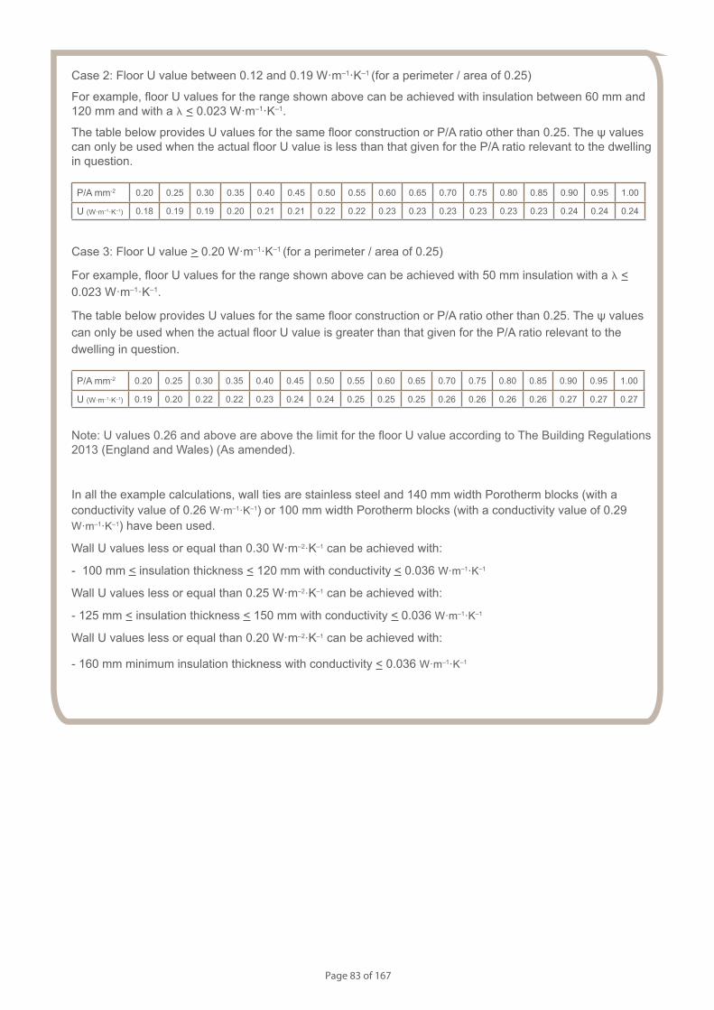
Page 83 of 167
Case 2: Floor U value between 0.12 and 0.19 W·m–1·K–1 (for a perimeter / area of 0.25)
For example, floor U values for the range shown above can be achieved with insulation between 60 mm and 120 mm and with a l < 0.023 W·m–1·K–1.
The table below provides U values for the same floor construction or P/A ratio other than 0.25. The ψ values can only be used when the actual floor U value is less than that given for the P/A ratio relevant to the dwelling in question.
P/A mm-2 0.20 0.25 0.30 0.35 0.40 0.45 0.50 0.55 0.60 0.65 0.70 0.75 0.80 0.85 0.90 0.95 1.00
U (W·m–1·K–1) 0.18 0.19 0.19 0.20 0.21 0.21 0.22 0.22 0.23 0.23 0.23 0.23 0.23 0.23 0.24 0.24 0.24
Case 3: Floor U value > 0.20 W·m–1·K–1 (for a perimeter / area of 0.25)
For example, floor U values for the range shown above can be achieved with 50 mm insulation with a l < 0.023 W·m–1·K–1.
The table below provides U values for the same floor construction or P/A ratio other than 0.25. The ψ values can only be used when the actual floor U value is greater than that given for the P/A ratio relevant to the dwelling in question.
P/A mm-2 0.20 0.25 0.30 0.35 0.40 0.45 0.50 0.55 0.60 0.65 0.70 0.75 0.80 0.85 0.90 0.95 1.00
U (W·m–1·K–1) 0.19 0.20 0.22 0.22 0.23 0.24 0.24 0.25 0.25 0.25 0.26 0.26 0.26 0.26 0.27 0.27 0.27
Note: U values 0.26 and above are above the limit for the floor U value according to The Building Regulations 2013 (England and Wales) (As amended).
In all the example calculations, wall ties are stainless steel and 140 mm width Porotherm blocks (with a conductivity value of 0.26 W·m–1·K–1) or 100 mm width Porotherm blocks (with a conductivity value of 0.29 W·m–1·K–1) have been used.
Wall U values less or equal than 0.30 W·m–2·K–1 can be achieved with:
- 100 mm < insulation thickness < 120 mm with conductivity < 0.036 W·m–1·K–1
Wall U values less or equal than 0.25 W·m–2·K–1 can be achieved with:
- 125 mm < insulation thickness < 150 mm with conductivity < 0.036 W·m–1·K–1
Wall U values less or equal than 0.20 W·m–2·K–1 can be achieved with:
- 160 mm minimum insulation thickness with conductivity < 0.036 W·m–1·K–1
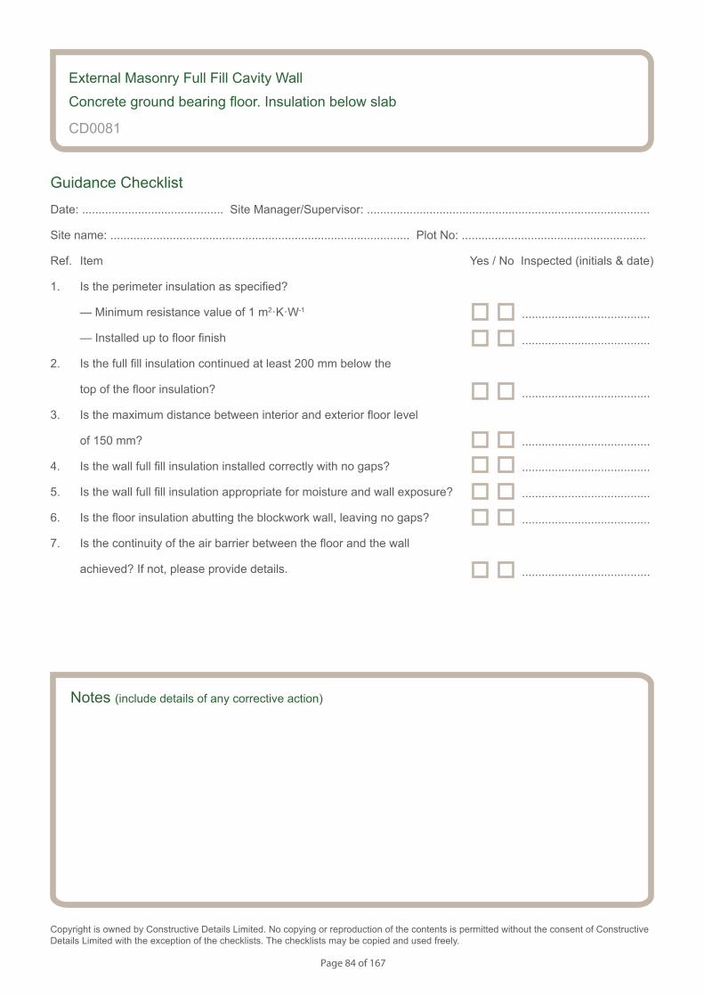
Page 84 of 167
Notes (include details of any corrective action)
CD0081
Guidance Checklist
Date: ........................................... Site Manager/Supervisor: ......................................................................................
Site name: ........................................................................................... Plot No: ........................................................
Ref. Item Yes / No Inspected (initials & date)
1. Is the perimeter insulation as specified?
— Minimum resistance value of 1 m2·K·W-1
— Installed up to floor finish
2. Is the full fill insulation continued at least 200 mm below the
top of the floor insulation?
3. Is the maximum distance between interior and exterior floor level
of 150 mm?
4. Is the wall full fill insulation installed correctly with no gaps?
5. Is the wall full fill insulation appropriate for moisture and wall exposure?
6. Is the floor insulation abutting the blockwork wall, leaving no gaps?
7. Is the continuity of the air barrier between the floor and the wall
achieved? If not, please provide details.
Copyright is owned by Constructive Details Limited. No copying or reproduction of the contents is permitted without the consent of Constructive Details Limited with the exception of the checklists. The checklists may be copied and used freely.
.......................................
.......................................
.......................................
.......................................
.......................................
.......................................
.......................................
.......................................
External Masonry Full Fill Cavity Wall
Concrete ground bearing floor. Insulation below slab
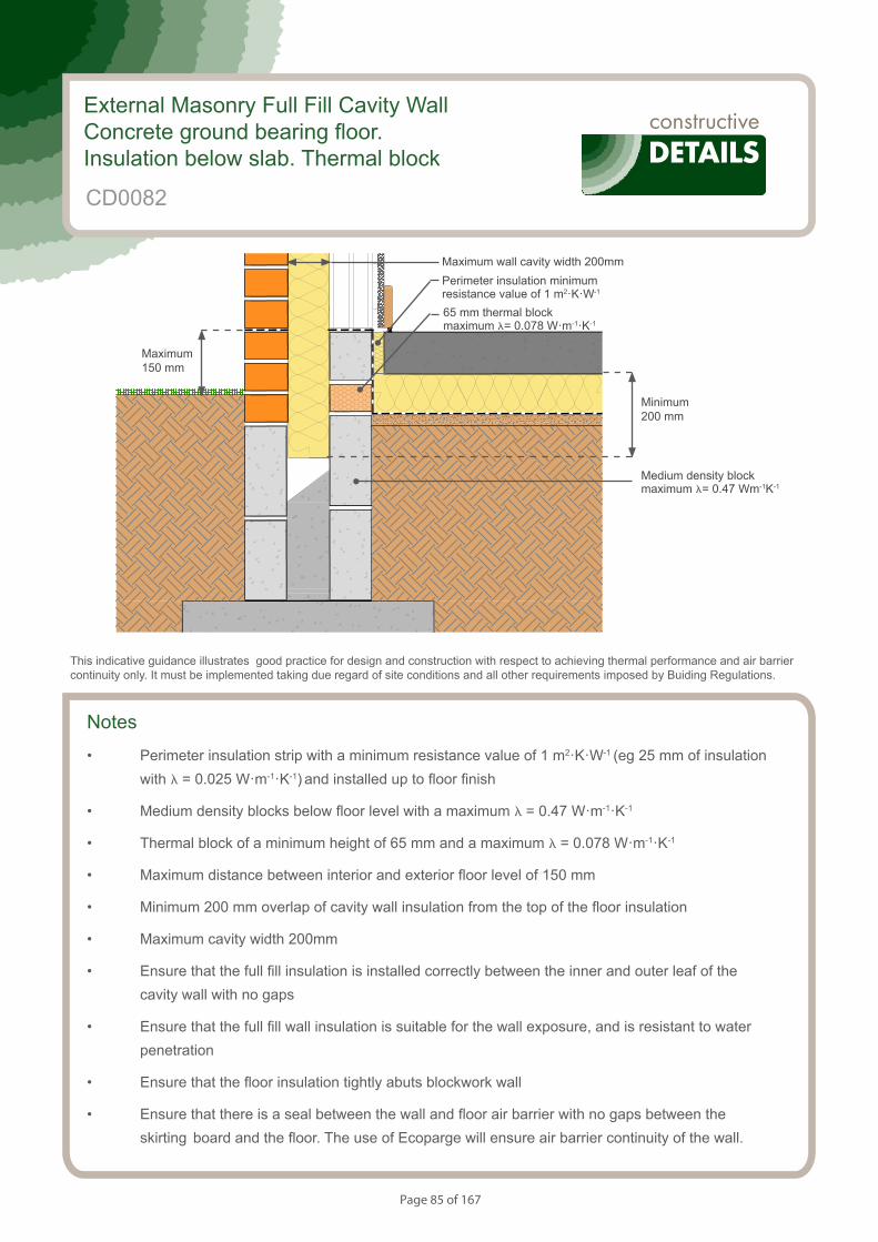
Page 85 of 167
Notes
• Perimeter insulation strip with a minimum resistance value of 1 m2·K·W-1 (eg 25 mm of insulation with l = 0.025 W·m-1·K-1) and installed up to floor finish
• Medium density blocks below floor level with a maximum l = 0.47 W·m-1·K-1
• Thermal block of a minimum height of 65 mm and a maximum l = 0.078 W·m-1·K-1
• Maximum distance between interior and exterior floor level of 150 mm
• Minimum 200 mm overlap of cavity wall insulation from the top of the floor insulation
• Maximum cavity width 200mm
• Ensure that the full fill insulation is installed correctly between the inner and outer leaf of the cavity wall with no gaps
• Ensure that the full fill wall insulation is suitable for the wall exposure, and is resistant to water penetration
• Ensure that the floor insulation tightly abuts blockwork wall
• Ensure that there is a seal between the wall and floor air barrier with no gaps between the skirting board and the floor. The use of Ecoparge will ensure air barrier continuity of the wall.
S154083_CD4-1
Concrete Ground Bearing Floor. Insulation Below Slab.Thermal block
External Masonry Full Fill Cavity WallConcrete ground bearing floor. Insulation below slab. Thermal block
CD0082
This indicative guidance illustrates good practice for design and construction with respect to achieving thermal performance and air barrier continuity only. It must be implemented taking due regard of site conditions and all other requirements imposed by Buiding Regulations.
Minimum 200 mm
Maximum 150 mm
Medium density block maximum l= 0.47 Wm-1K-1
Maximum wall cavity width 200mmPerimeter insulation minimum resistance value of 1 m2·K·W-1
65 mm thermal block maximum l= 0.078 W·m-1·K-1
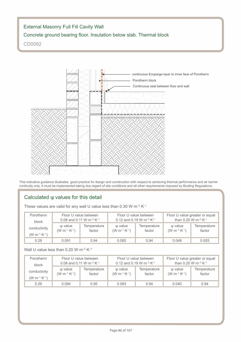
Page 86 of 167
S154083_CD4-2
Concrete Ground Bearing Floor. Insulation Below Slab.Thermal block
Calculated ψ values for this detail
These values are valid for any wall U value less than 0.30 W·m–2·K–1
Porotherm
block
conductivity
(W·m–1·K–1)
Floor U value between 0.08 and 0.11 W·m–2·K–1
Floor U value between 0.12 and 0.19 W·m–2·K–1
Floor U value greater or equal than 0.20 W·m–2·K–1
ψ value (W·m–1·K–1)
Temperaturefactor
ψ value (W·m–1·K–1)
Temperaturefactor
ψ value (W·m–1·K–1)
Temperaturefactor
0.29 0.091 0.94 0.082 0.94 0.048 0.925
Wall U value less than 0.20 W·m–2·K–1
Porotherm
block
conductivity
(W·m–1·K–1)
Floor U value between 0.08 and 0.11 W·m–2·K–1
Floor U value between 0.12 and 0.19 W·m–2·K–1
Floor U value greater or equal than 0.20 W·m–2·K–1
ψ value (W·m–1·K–1)
Temperaturefactor
ψ value (W·m–1·K–1)
Temperaturefactor
ψ value (W·m–1·K–1)
Temperaturefactor
0.26 0.094 0.95 0.083 0.94 0.040 0.94
External Masonry Full Fill Cavity Wall
Concrete ground bearing floor. Insulation below slab. Thermal block
CD0082
This indicative guidance illustrates good practice for design and construction with respect to achieving thermal performance and air barrier continuity only. It must be implemented taking due regard of site conditions and all other requirements imposed by Buiding Regulations.
continuous Ecoparge layer to inner face of Porotherm
Continuous seal between floor and wall
Porotherm block
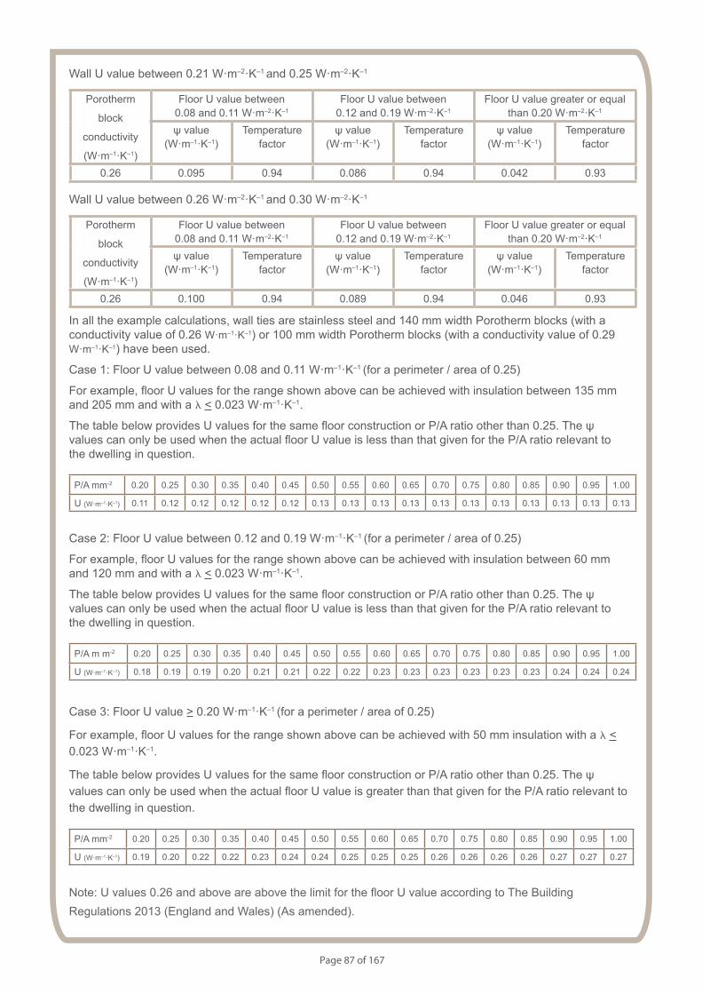
Page 87 of 167
Wall U value between 0.21 W·m–2·K–1 and 0.25 W·m–2·K–1
Porotherm
block
conductivity
(W·m–1·K–1)
Floor U value between 0.08 and 0.11 W·m–2·K–1
Floor U value between 0.12 and 0.19 W·m–2·K–1
Floor U value greater or equal than 0.20 W·m–2·K–1
ψ value (W·m–1·K–1)
Temperaturefactor
ψ value (W·m–1·K–1)
Temperaturefactor
ψ value (W·m–1·K–1)
Temperaturefactor
0.26 0.095 0.94 0.086 0.94 0.042 0.93
Wall U value between 0.26 W·m–2·K–1 and 0.30 W·m–2·K–1
Porotherm
block
conductivity
(W·m–1·K–1)
Floor U value between 0.08 and 0.11 W·m–2·K–1
Floor U value between 0.12 and 0.19 W·m–2·K–1
Floor U value greater or equal than 0.20 W·m–2·K–1
ψ value (W·m–1·K–1)
Temperaturefactor
ψ value (W·m–1·K–1)
Temperaturefactor
ψ value (W·m–1·K–1)
Temperaturefactor
0.26 0.100 0.94 0.089 0.94 0.046 0.93
In all the example calculations, wall ties are stainless steel and 140 mm width Porotherm blocks (with a conductivity value of 0.26 W·m–1·K–1) or 100 mm width Porotherm blocks (with a conductivity value of 0.29 W·m–1·K–1) have been used.
Case 1: Floor U value between 0.08 and 0.11 W·m–1·K–1 (for a perimeter / area of 0.25)
For example, floor U values for the range shown above can be achieved with insulation between 135 mm and 205 mm and with a l < 0.023 W·m–1·K–1.
The table below provides U values for the same floor construction or P/A ratio other than 0.25. The ψ values can only be used when the actual floor U value is less than that given for the P/A ratio relevant to the dwelling in question.
P/A mm-2 0.20 0.25 0.30 0.35 0.40 0.45 0.50 0.55 0.60 0.65 0.70 0.75 0.80 0.85 0.90 0.95 1.00
U (W·m–1·K–1) 0.11 0.12 0.12 0.12 0.12 0.12 0.13 0.13 0.13 0.13 0.13 0.13 0.13 0.13 0.13 0.13 0.13
Case 2: Floor U value between 0.12 and 0.19 W·m–1·K–1 (for a perimeter / area of 0.25)
For example, floor U values for the range shown above can be achieved with insulation between 60 mm and 120 mm and with a l < 0.023 W·m–1·K–1.
The table below provides U values for the same floor construction or P/A ratio other than 0.25. The ψ values can only be used when the actual floor U value is less than that given for the P/A ratio relevant to the dwelling in question.
P/A m m-2 0.20 0.25 0.30 0.35 0.40 0.45 0.50 0.55 0.60 0.65 0.70 0.75 0.80 0.85 0.90 0.95 1.00
U (W·m–1·K–1) 0.18 0.19 0.19 0.20 0.21 0.21 0.22 0.22 0.23 0.23 0.23 0.23 0.23 0.23 0.24 0.24 0.24
Case 3: Floor U value > 0.20 W·m–1·K–1 (for a perimeter / area of 0.25)
For example, floor U values for the range shown above can be achieved with 50 mm insulation with a l < 0.023 W·m–1·K–1.
The table below provides U values for the same floor construction or P/A ratio other than 0.25. The ψ values can only be used when the actual floor U value is greater than that given for the P/A ratio relevant to the dwelling in question.
P/A mm-2 0.20 0.25 0.30 0.35 0.40 0.45 0.50 0.55 0.60 0.65 0.70 0.75 0.80 0.85 0.90 0.95 1.00
U (W·m–1·K–1) 0.19 0.20 0.22 0.22 0.23 0.24 0.24 0.25 0.25 0.25 0.26 0.26 0.26 0.26 0.27 0.27 0.27
Note: U values 0.26 and above are above the limit for the floor U value according to The Building Regulations 2013 (England and Wales) (As amended).
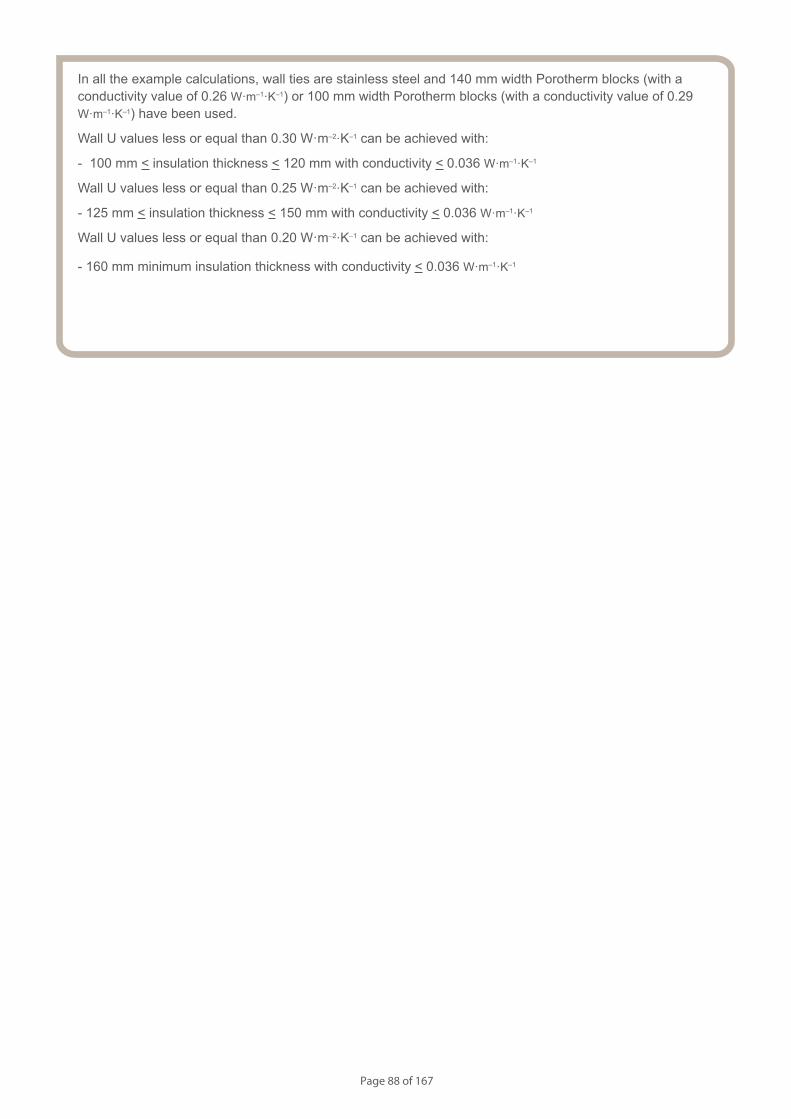
Page 88 of 167
In all the example calculations, wall ties are stainless steel and 140 mm width Porotherm blocks (with a conductivity value of 0.26 W·m–1·K–1) or 100 mm width Porotherm blocks (with a conductivity value of 0.29 W·m–1·K–1) have been used.
Wall U values less or equal than 0.30 W·m–2·K–1 can be achieved with:
- 100 mm < insulation thickness < 120 mm with conductivity < 0.036 W·m–1·K–1
Wall U values less or equal than 0.25 W·m–2·K–1 can be achieved with:
- 125 mm < insulation thickness < 150 mm with conductivity < 0.036 W·m–1·K–1
Wall U values less or equal than 0.20 W·m–2·K–1 can be achieved with:
- 160 mm minimum insulation thickness with conductivity < 0.036 W·m–1·K–1
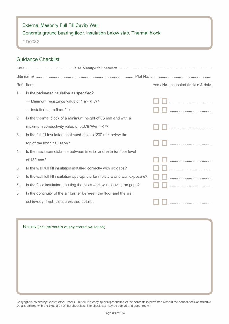
Page 89 of 167
Notes (include details of any corrective action)
CD0082
Guidance Checklist
Date: ........................................... Site Manager/Supervisor: ......................................................................................
Site name: ........................................................................................... Plot No: ........................................................
Ref. Item Yes / No Inspected (initials & date)
1. Is the perimeter insulation as specified?
— Minimum resistance value of 1 m2·K·W-1
— Installed up to floor finish
2. Is the thermal block of a minimum height of 65 mm and with a
maximum conductivity value of 0.078 W·m-1·K-1?
3. Is the full fill insulation continued at least 200 mm below the
top of the floor insulation?
4. Is the maximum distance between interior and exterior floor level
of 150 mm?
5. Is the wall full fill insulation installed correctly with no gaps?
6. Is the wall full fill insulation appropriate for moisture and wall exposure?
7. Is the floor insulation abutting the blockwork wall, leaving no gaps?
8. Is the continuity of the air barrier between the floor and the wall
achieved? If not, please provide details.
Copyright is owned by Constructive Details Limited. No copying or reproduction of the contents is permitted without the consent of Constructive Details Limited with the exception of the checklists. The checklists may be copied and used freely.
.......................................
.......................................
.......................................
.......................................
.......................................
.......................................
.......................................
.......................................
External Masonry Full Fill Cavity Wall
Concrete ground bearing floor. Insulation below slab. Thermal block
.......................................
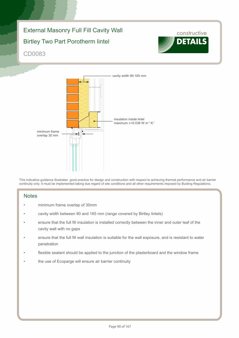
Page 90 of 167
S154083_CD25-1
Birtley lintel
Notes
• minimum frame overlap of 30mm
• cavity width between 90 and 165 mm (range covered by Birtley lintels)
• ensure that the full fill insulation is installed correctly between the inner and outer leaf of the cavity wall with no gaps
• ensure that the full fill wall insulation is suitable for the wall exposure, and is resistant to water penetration
• flexible sealant should be applied to the junction of the plasterboard and the window frame
• the use of Ecoparge will ensure air barrier continuity
External Masonry Full Fill Cavity Wall
Birtley Two Part Porotherm lintel
CD0083
This indicative guidance illustrates good practice for design and construction with respect to achieving thermal performance and air barrier continuity only. It must be implemented taking due regard of site conditions and all other requirements imposed by Buiding Regulations.
minimum frame overlap 30 mm
cavity width 90-165 mm
insulation inside lintel maximum l=0.038 W·m-1·K-1
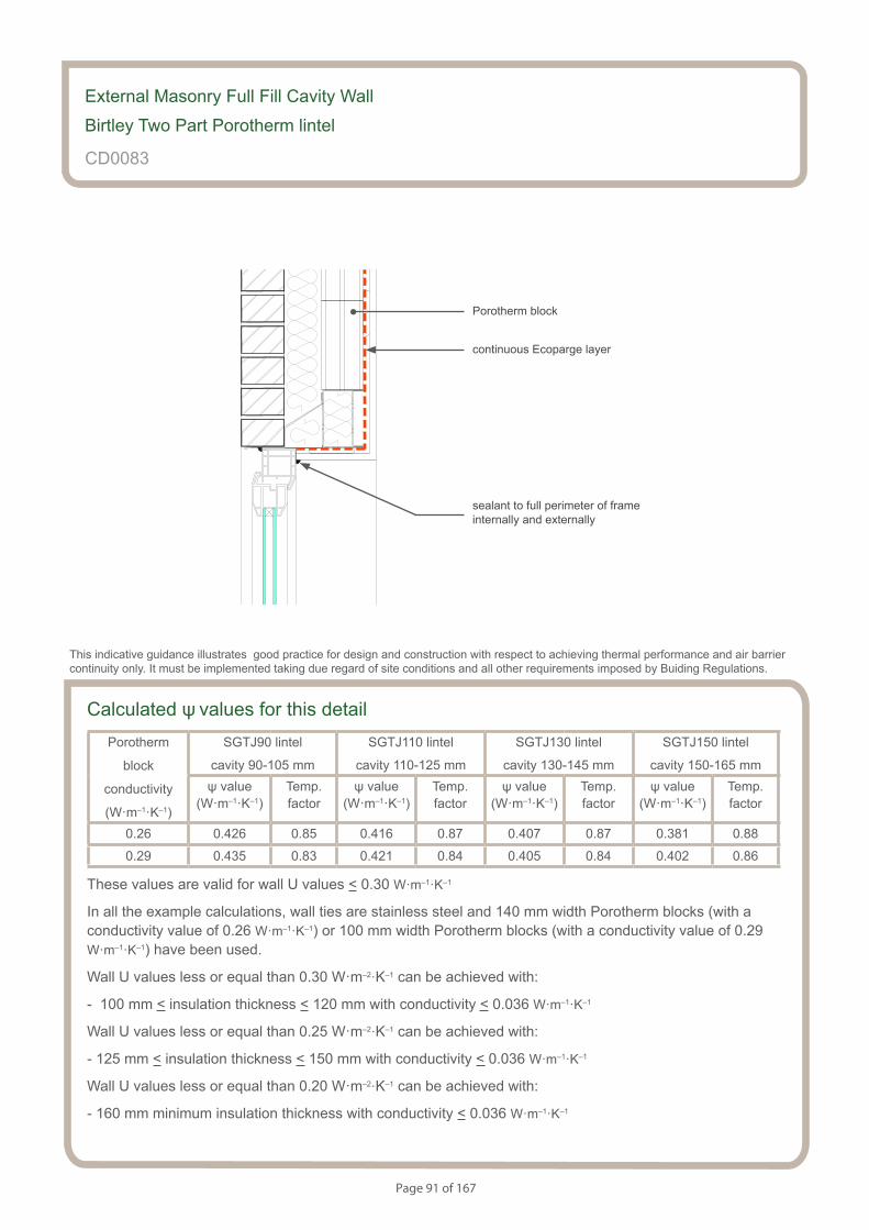
Page 91 of 167
S154083_CD25-2
Birtley lintel
Calculated ψ values for this detailPorotherm
block
conductivity
(W·m–1·K–1)
SGTJ90 lintel
cavity 90-105 mm
SGTJ110 lintel
cavity 110-125 mm
SGTJ130 lintel
cavity 130-145 mm
SGTJ150 lintel
cavity 150-165 mmψ value
(W·m–1·K–1)Temp.factor
ψ value (W·m–1·K–1)
Temp.factor
ψ value (W·m–1·K–1)
Temp.factor
ψ value (W·m–1·K–1)
Temp.factor
0.26 0.426 0.85 0.416 0.87 0.407 0.87 0.381 0.88
0.29 0.435 0.83 0.421 0.84 0.405 0.84 0.402 0.86
These values are valid for wall U values < 0.30 W·m–1·K–1
In all the example calculations, wall ties are stainless steel and 140 mm width Porotherm blocks (with a conductivity value of 0.26 W·m–1·K–1) or 100 mm width Porotherm blocks (with a conductivity value of 0.29 W·m–1·K–1) have been used.
Wall U values less or equal than 0.30 W·m–2·K–1 can be achieved with:
- 100 mm < insulation thickness < 120 mm with conductivity < 0.036 W·m–1·K–1
Wall U values less or equal than 0.25 W·m–2·K–1 can be achieved with:
- 125 mm < insulation thickness < 150 mm with conductivity < 0.036 W·m–1·K–1
Wall U values less or equal than 0.20 W·m–2·K–1 can be achieved with:
- 160 mm minimum insulation thickness with conductivity < 0.036 W·m–1·K–1
External Masonry Full Fill Cavity Wall
Birtley Two Part Porotherm lintel
CD0083
sealant to full perimeter of frame internally and externally
This indicative guidance illustrates good practice for design and construction with respect to achieving thermal performance and air barrier continuity only. It must be implemented taking due regard of site conditions and all other requirements imposed by Buiding Regulations.
continuous Ecoparge layer
Porotherm block
Page 92 of 167
Notes (include details of any corrective action)
External Masonry Full Fill Cavity Wall
Birtley Two Part Porotherm lintel
CD0083
Guidance Checklist
Date: ........................................... Site Manager/Supervisor: ......................................................................................
Site name: ........................................................................................... Plot No: ........................................................
Ref. Item Yes / No Inspected (initials & date)
1. Is there a minimum frame overlap of 30mm?
2. Is the Cavity width between 90 and 165 mm?
3. Is the the full fill insulation is installed correctly between the inner
and outer leaf of the cavity wall with no gaps?
4. Is the full fill wall insulation suitable for the wall exposure, and
is it resistant to water penetration ?
5. Has flexible sealant been be applied to the junction of the
plasterboard and the window frame?
6. Is Ecoparge used to ensure air barrier continuity?
Copyright is owned by Constructive Details Limited. No copying or reproduction of the contents is permitted without the consent of Constructive Details Limited with the exception of the checklists. The checklists may be copied and used freely.
.......................................
.......................................
.......................................
.......................................
.......................................
.......................................

Page 93 of 167
S154083_CD26-1
Catnic lintel
Notes
• minimum frame overlap of 30mm
• cavity width between 90 and 165 mm (range covered by Catnic lintels)
• ensure that the full fill insulation is installed correctly between the inner and outer leaf of the cavity wall with no gaps
• ensure that the full fill wall insulation is suitable for the wall exposure, and is resistant to water penetration
• flexible sealant should be applied to the junction of the plasterboard and the window frame
• the use of Ecoparge will ensure air barrier continuity
External Masonry Full Fill Cavity Wall
Catnic CTJ lintel
CD0084
This indicative guidance illustrates good practice for design and construction with respect to achieving thermal performance and air barrier continuity only. It must be implemented taking due regard of site conditions and all other requirements imposed by Buiding Regulations.
minimum frame overlap 30 mm
cavity width 90-165 mm
insulation inside lintel maximum l=0.038 W·m-1·K-1
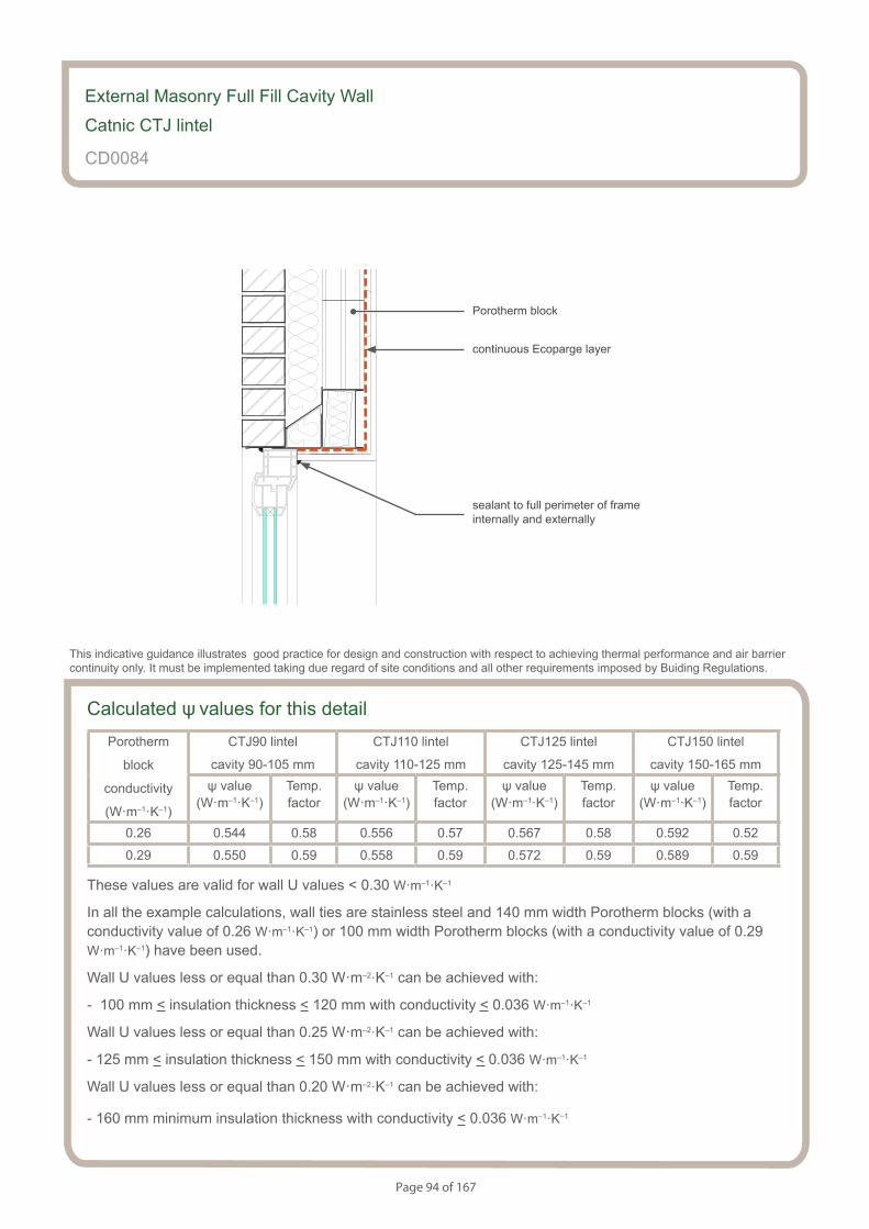
Page 94 of 167
S154083_CD26-2
Catnic lintel
External Masonry Full Fill Cavity Wall
Catnic CTJ lintel
CD0084
sealant to full perimeter of frame internally and externally
This indicative guidance illustrates good practice for design and construction with respect to achieving thermal performance and air barrier continuity only. It must be implemented taking due regard of site conditions and all other requirements imposed by Buiding Regulations.
continuous Ecoparge layer
Porotherm block
Calculated ψ values for this detailPorotherm
block
conductivity
(W·m–1·K–1)
CTJ90 lintel
cavity 90-105 mm
CTJ110 lintel
cavity 110-125 mm
CTJ125 lintel
cavity 125-145 mm
CTJ150 lintel
cavity 150-165 mmψ value
(W·m–1·K–1)Temp.factor
ψ value (W·m–1·K–1)
Temp.factor
ψ value (W·m–1·K–1)
Temp.factor
ψ value (W·m–1·K–1)
Temp.factor
0.26 0.544 0.58 0.556 0.57 0.567 0.58 0.592 0.52
0.29 0.550 0.59 0.558 0.59 0.572 0.59 0.589 0.59
These values are valid for wall U values < 0.30 W·m–1·K–1
In all the example calculations, wall ties are stainless steel and 140 mm width Porotherm blocks (with a conductivity value of 0.26 W·m–1·K–1) or 100 mm width Porotherm blocks (with a conductivity value of 0.29 W·m–1·K–1) have been used.
Wall U values less or equal than 0.30 W·m–2·K–1 can be achieved with:
- 100 mm < insulation thickness < 120 mm with conductivity < 0.036 W·m–1·K–1
Wall U values less or equal than 0.25 W·m–2·K–1 can be achieved with:
- 125 mm < insulation thickness < 150 mm with conductivity < 0.036 W·m–1·K–1
Wall U values less or equal than 0.20 W·m–2·K–1 can be achieved with:
- 160 mm minimum insulation thickness with conductivity < 0.036 W·m–1·K–1
Page 95 of 167
Notes (include details of any corrective action)
External Masonry Full Fill Cavity Wall
Catnic CTJ lintel
CD0084
Guidance Checklist
Date: ........................................... Site Manager/Supervisor: ......................................................................................
Site name: ........................................................................................... Plot No: ........................................................
Ref. Item Yes / No Inspected (initials & date)
1. 1. Is there a minimum frame overlap of 30mm?
2. Is the Cavity width between 90 and 165 mm?
3. Is the the full fill insulation is installed correctly between the inner
and outer leaf of the cavity wall with no gaps?
4. Is the full fill wall insulation suitable for the wall exposure, and
is it resistant to water penetration ?
5. Has flexible sealant been be applied to the junction of the
plasterboard and the window frame?
6. Is Ecoparge used to ensure air barrier continuity?
Copyright is owned by Constructive Details Limited. No copying or reproduction of the contents is permitted without the consent of Constructive Details Limited with the exception of the checklists. The checklists may be copied and used freely.
.......................................
.......................................
.......................................
.......................................
.......................................
.......................................

Page 96 of 167
S154083_CD27-1
Porocav lintel
Notes
• minimum frame overlap of 30mm
• cavity width between 90 and 165 mm (range covered by Porocav lintels)
• ensure that the full fill insulation is installed correctly between the inner and outer leaf of the cavity wall with no gaps
• ensure that the full fill wall insulation is suitable for the wall exposure, and is resistant to water penetration
• flexible sealant should be applied to the junction of the plasterboard and the window frame
• the use of Ecoparge will ensure air barrier continuity
External Masonry Full Fill Cavity Wall
Keystone Poro-Cav lintel
CD0085
This indicative guidance illustrates good practice for design and construction with respect to achieving thermal performance and air barrier continuity only. It must be implemented taking due regard of site conditions and all other requirements imposed by Buiding Regulations.
minimum frame overlap 30 mm
cavity width 90-165 mm
insulation inside lintel maximum l=0.035 W·m-1·K-1
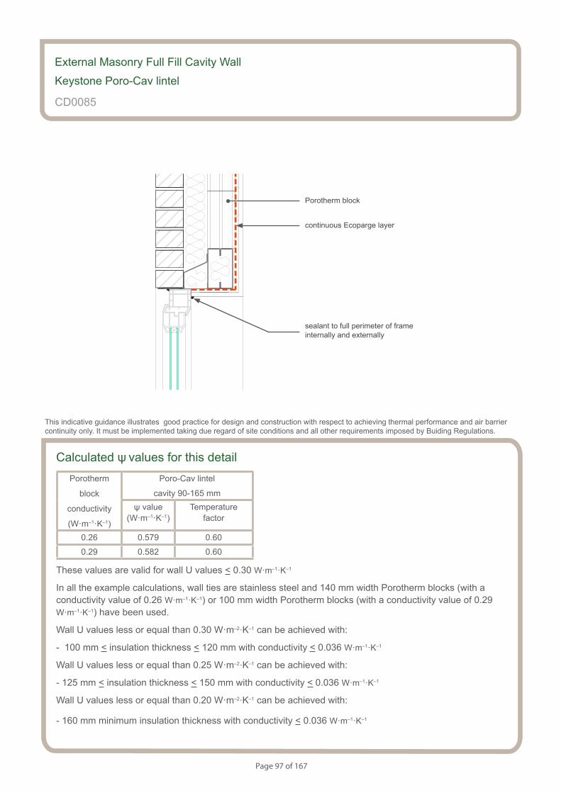
Page 97 of 167
S154083_CD27-2
Porocav lintel
External Masonry Full Fill Cavity Wall
Keystone Poro-Cav lintel
CD0085
sealant to full perimeter of frame internally and externally
This indicative guidance illustrates good practice for design and construction with respect to achieving thermal performance and air barrier continuity only. It must be implemented taking due regard of site conditions and all other requirements imposed by Buiding Regulations.
continuous Ecoparge layer
Porotherm block
Calculated ψ values for this detailPorotherm
block
conductivity
(W·m–1·K–1)
Poro-Cav lintel
cavity 90-165 mmψ value
(W·m–1·K–1)Temperature
factor
0.26 0.579 0.60
0.29 0.582 0.60
These values are valid for wall U values < 0.30 W·m–1·K–1
In all the example calculations, wall ties are stainless steel and 140 mm width Porotherm blocks (with a conductivity value of 0.26 W·m–1·K–1) or 100 mm width Porotherm blocks (with a conductivity value of 0.29 W·m–1·K–1) have been used.
Wall U values less or equal than 0.30 W·m–2·K–1 can be achieved with:
- 100 mm < insulation thickness < 120 mm with conductivity < 0.036 W·m–1·K–1
Wall U values less or equal than 0.25 W·m–2·K–1 can be achieved with:
- 125 mm < insulation thickness < 150 mm with conductivity < 0.036 W·m–1·K–1
Wall U values less or equal than 0.20 W·m–2·K–1 can be achieved with:
- 160 mm minimum insulation thickness with conductivity < 0.036 W·m–1·K–1

Page 98 of 167
Notes (include details of any corrective action)
External Masonry Full Fill Cavity Wall
Keystone Poro-Cav lintel
CD0085
Guidance Checklist
Date: ........................................... Site Manager/Supervisor: ......................................................................................
Site name: ........................................................................................... Plot No: ........................................................
Ref. Item Yes / No Inspected (initials & date)
1. Is there a minimum frame overlap of 30mm?
2. Is the Cavity width between 90 and 165 mm?
3. Is the the full fill insulation is installed correctly between the inner
and outer leaf of the cavity wall with no gaps?
4. Is the full fill wall insulation suitable for the wall exposure, and
is it resistant to water penetration ?
5. Has flexible sealant been be applied to the junction of the
plasterboard and the window frame?
6. Is Ecoparge used to ensure air barrier continuity?
Copyright is owned by Constructive Details Limited. No copying or reproduction of the contents is permitted without the consent of Constructive Details Limited with the exception of the checklists. The checklists may be copied and used freely.
.......................................
.......................................
.......................................
.......................................
.......................................
.......................................

Page 99 of 167
S154083_CD28-1
Box and angle lintel
Notes
• minimum frame overlap of 30mm
• maximum cavity width 200 mm
• ensure that the full fill insulation is installed correctly between the inner and outer leaf of the cavity wall with no gaps
• ensure that the full fill wall insulation is suitable for the wall exposure, and is resistant to water penetration
• flexible sealant should be applied to the junction of the plasterboard and the window frame
• the use of Ecoparge will ensure air barrier continuity
External Masonry Full Fill Cavity Wall
Box and angle lintel
CD0086
This indicative guidance illustrates good practice for design and construction with respect to achieving thermal performance and air barrier continuity only. It must be implemented taking due regard of site conditions and all other requirements imposed by Buiding Regulations.
minimum frame overlap 30 mm
maximum wall cavity width 200mm
insulation inside lintel maximum l=0.038 W·m-1·K-1
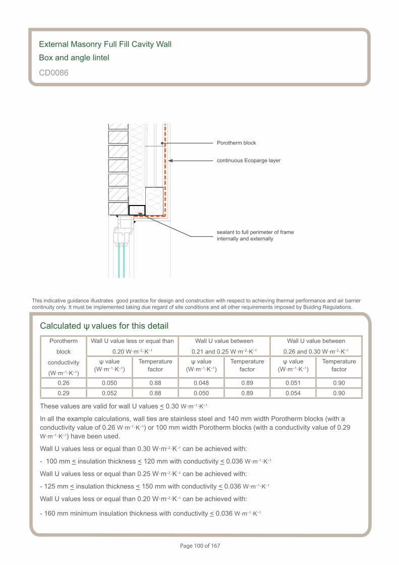
Page 100 of 167
S154083_CD28-2
Box and angle lintel
Calculated ψ values for this detailPorotherm
block
conductivity
(W·m–1·K–1)
Wall U value less or equal than
0.20 W·m–2·K–1
Wall U value between
0.21 and 0.25 W·m–2·K–1
Wall U value between
0.26 and 0.30 W·m–2·K–1
ψ value (W·m–1·K–1)
Temperaturefactor
ψ value (W·m–1·K–1)
Temperaturefactor
ψ value (W·m–1·K–1)
Temperaturefactor
0.26 0.050 0.88 0.048 0.89 0.051 0.90
0.29 0.052 0.88 0.050 0.89 0.054 0.90
These values are valid for wall U values < 0.30 W·m–1·K–1
In all the example calculations, wall ties are stainless steel and 140 mm width Porotherm blocks (with a conductivity value of 0.26 W·m–1·K–1) or 100 mm width Porotherm blocks (with a conductivity value of 0.29 W·m–1·K–1) have been used.
Wall U values less or equal than 0.30 W·m–2·K–1 can be achieved with:
- 100 mm < insulation thickness < 120 mm with conductivity < 0.036 W·m–1·K–1
Wall U values less or equal than 0.25 W·m–2·K–1 can be achieved with:
- 125 mm < insulation thickness < 150 mm with conductivity < 0.036 W·m–1·K–1
Wall U values less or equal than 0.20 W·m–2·K–1 can be achieved with:
- 160 mm minimum insulation thickness with conductivity < 0.036 W·m–1·K–1
External Masonry Full Fill Cavity Wall
Box and angle lintel
CD0086
sealant to full perimeter of frame internally and externally
This indicative guidance illustrates good practice for design and construction with respect to achieving thermal performance and air barrier continuity only. It must be implemented taking due regard of site conditions and all other requirements imposed by Buiding Regulations.
continuous Ecoparge layer
Porotherm block
Page 101 of 167
Notes (include details of any corrective action)
External Masonry Full Fill Cavity Wall
Box and angle lintel
CD0086
Guidance Checklist
Date: ........................................... Site Manager/Supervisor: ......................................................................................
Site name: ........................................................................................... Plot No: ........................................................
Ref. Item Yes / No Inspected (initials & date)
1. Is there a minimum frame overlap of 30mm?
2. Is there a maximum cavity width 200 mm?
3. Is the full fill insulation installed correctly between the inner and
outer leaf of the cavity wall with no gaps?
4. Is the full fill wall insulation is suitable for the wall exposure, and
is it resistant to water penetration?
5. Is flexible sealant applied to the junction of the plasterboard and
the window frame?
6. Is Ecoparge used to ensure air barrier continuity?
Copyright is owned by Constructive Details Limited. No copying or reproduction of the contents is permitted without the consent of Constructive Details Limited with the exception of the checklists. The checklists may be copied and used freely.
.......................................
.......................................
.......................................
.......................................
.......................................
.......................................
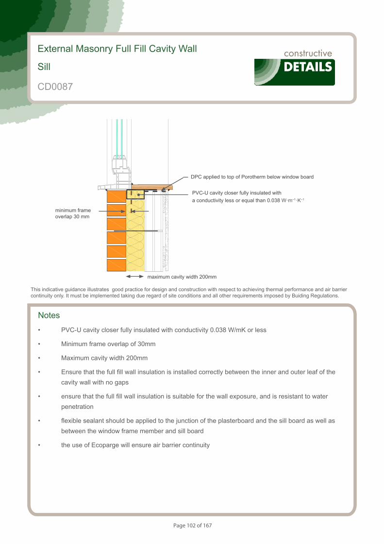
Page 102 of 167
Notes
• PVC-U cavity closer fully insulated with conductivity 0.038 W/mK or less
• Minimum frame overlap of 30mm
• Maximum cavity width 200mm
• Ensure that the full fill wall insulation is installed correctly between the inner and outer leaf of the cavity wall with no gaps
• ensure that the full fill wall insulation is suitable for the wall exposure, and is resistant to water penetration
• flexible sealant should be applied to the junction of the plasterboard and the sill board as well as between the window frame member and sill board
• the use of Ecoparge will ensure air barrier continuity
External Masonry Full Fill Cavity Wall
Sill
CD0087
This indicative guidance illustrates good practice for design and construction with respect to achieving thermal performance and air barrier continuity only. It must be implemented taking due regard of site conditions and all other requirements imposed by Buiding Regulations.
minimum frame overlap 30 mm
maximum cavity width 200mm
PVC-U cavity closer fully insulated with a conductivity less or equal than 0.038 W·m–1·K–1
DPC applied to top of Porotherm below window board
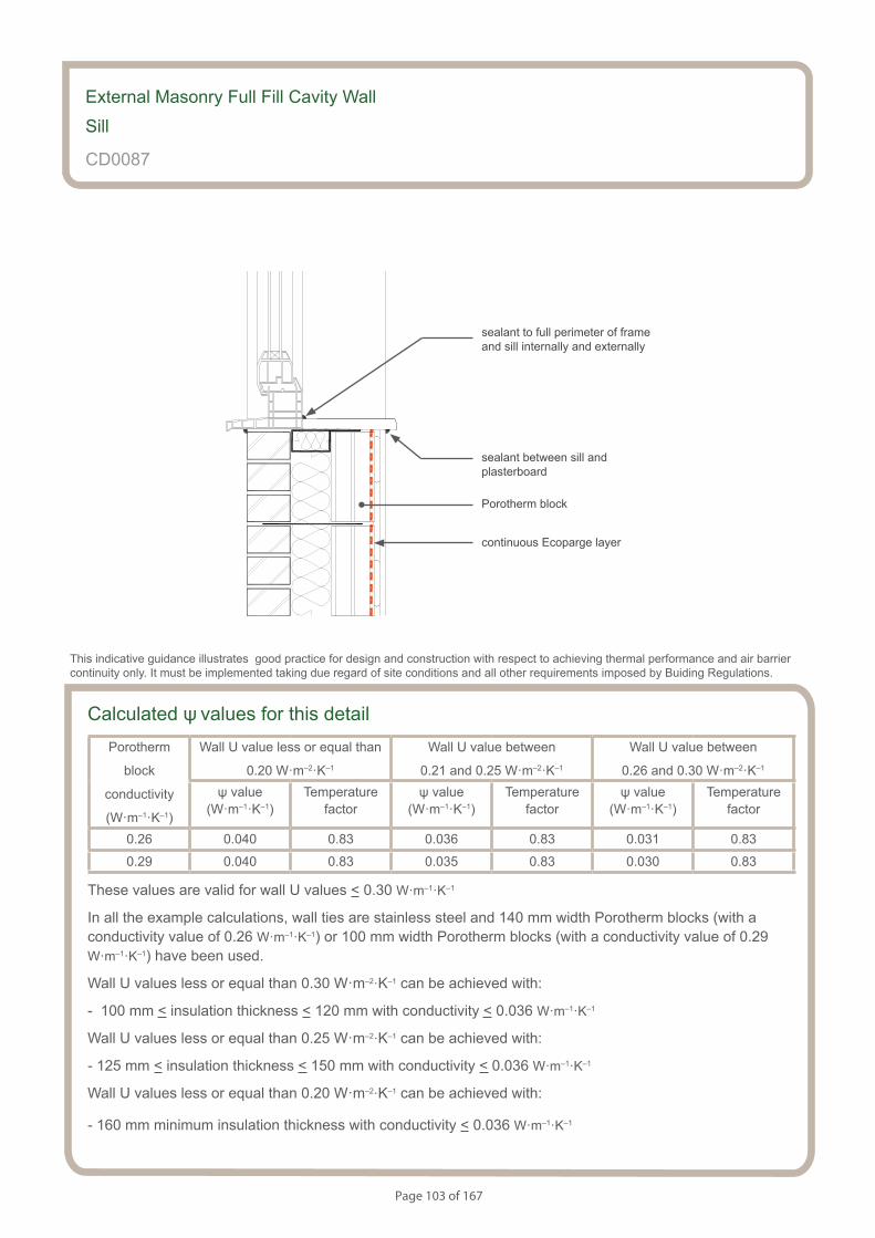
Page 103 of 167
Calculated ψ values for this detailPorotherm
block
conductivity
(W·m–1·K–1)
Wall U value less or equal than
0.20 W·m–2·K–1
Wall U value between
0.21 and 0.25 W·m–2·K–1
Wall U value between
0.26 and 0.30 W·m–2·K–1
ψ value (W·m–1·K–1)
Temperaturefactor
ψ value (W·m–1·K–1)
Temperaturefactor
ψ value (W·m–1·K–1)
Temperaturefactor
0.26 0.040 0.83 0.036 0.83 0.031 0.83
0.29 0.040 0.83 0.035 0.83 0.030 0.83
These values are valid for wall U values < 0.30 W·m–1·K–1
In all the example calculations, wall ties are stainless steel and 140 mm width Porotherm blocks (with a conductivity value of 0.26 W·m–1·K–1) or 100 mm width Porotherm blocks (with a conductivity value of 0.29 W·m–1·K–1) have been used.
Wall U values less or equal than 0.30 W·m–2·K–1 can be achieved with:
- 100 mm < insulation thickness < 120 mm with conductivity < 0.036 W·m–1·K–1
Wall U values less or equal than 0.25 W·m–2·K–1 can be achieved with:
- 125 mm < insulation thickness < 150 mm with conductivity < 0.036 W·m–1·K–1
Wall U values less or equal than 0.20 W·m–2·K–1 can be achieved with:
- 160 mm minimum insulation thickness with conductivity < 0.036 W·m–1·K–1
External Masonry Full Fill Cavity Wall
Sill
CD0087
sealant to full perimeter of frame and sill internally and externally
This indicative guidance illustrates good practice for design and construction with respect to achieving thermal performance and air barrier continuity only. It must be implemented taking due regard of site conditions and all other requirements imposed by Buiding Regulations.
sealant between sill and plasterboard
continuous Ecoparge layer
Porotherm block
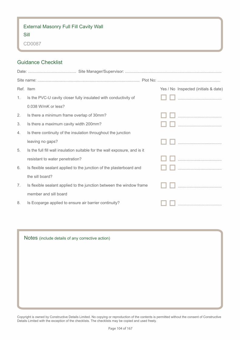
Page 104 of 167
Notes (include details of any corrective action)
External Masonry Full Fill Cavity Wall
Sill
CD0087
Guidance Checklist
Date: ........................................... Site Manager/Supervisor: ......................................................................................
Site name: ........................................................................................... Plot No: ........................................................
Ref. Item Yes / No Inspected (initials & date)
1. Is the PVC-U cavity closer fully insulated with conductivity of
0.038 W/mK or less?
2. Is there a minimum frame overlap of 30mm?
3. Is there a maximum cavity width 200mm?
4. Is there continuity of the insulation throughout the junction
leaving no gaps?
5. Is the full fill wall insulation suitable for the wall exposure, and is it
resistant to water penetration?
6. Is flexible sealant applied to the junction of the plasterboard and
the sill board?
7. Is flexible sealant applied to the junction between the window frame
member and sill board
8. Is Ecoparge applied to ensure air barrier continuity?
Copyright is owned by Constructive Details Limited. No copying or reproduction of the contents is permitted without the consent of Constructive Details Limited with the exception of the checklists. The checklists may be copied and used freely.
.......................................
.......................................
.......................................
.......................................
.......................................
.......................................
.......................................
.......................................
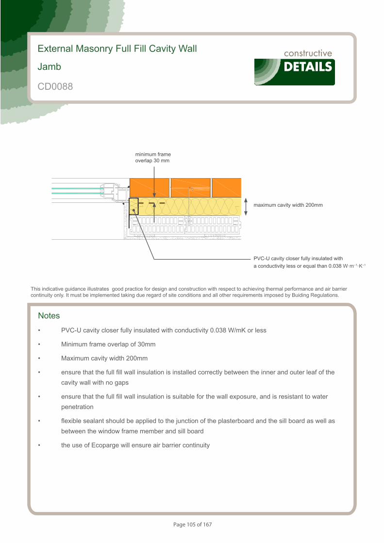
Page 105 of 167
Notes
• PVC-U cavity closer fully insulated with conductivity 0.038 W/mK or less
• Minimum frame overlap of 30mm
• Maximum cavity width 200mm
• ensure that the full fill wall insulation is installed correctly between the inner and outer leaf of the cavity wall with no gaps
• ensure that the full fill wall insulation is suitable for the wall exposure, and is resistant to water penetration
• flexible sealant should be applied to the junction of the plasterboard and the sill board as well as between the window frame member and sill board
• the use of Ecoparge will ensure air barrier continuity
External Masonry Full Fill Cavity Wall
Jamb
CD0088
This indicative guidance illustrates good practice for design and construction with respect to achieving thermal performance and air barrier continuity only. It must be implemented taking due regard of site conditions and all other requirements imposed by Buiding Regulations.
minimum frame overlap 30 mm
maximum cavity width 200mm
PVC-U cavity closer fully insulated with a conductivity less or equal than 0.038 W·m–1·K–1
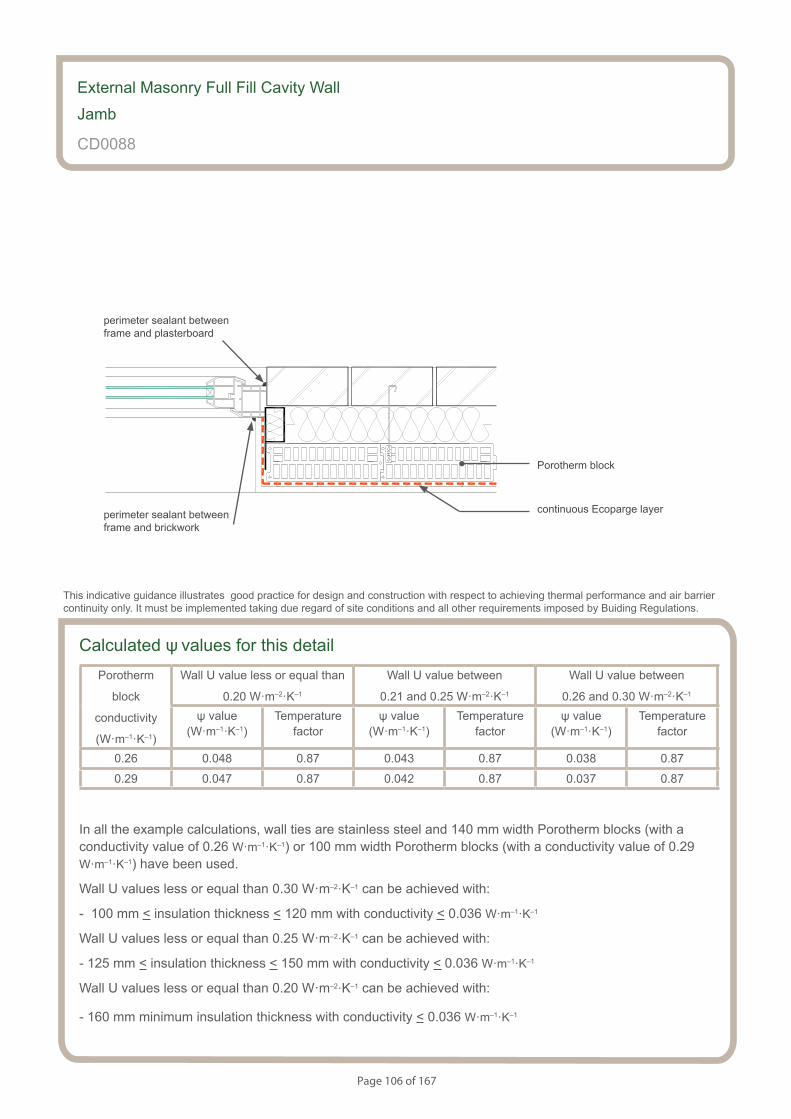
Page 106 of 167
Calculated ψ values for this detailPorotherm
block
conductivity
(W·m–1·K–1)
Wall U value less or equal than
0.20 W·m–2·K–1
Wall U value between
0.21 and 0.25 W·m–2·K–1
Wall U value between
0.26 and 0.30 W·m–2·K–1
ψ value (W·m–1·K–1)
Temperaturefactor
ψ value (W·m–1·K–1)
Temperaturefactor
ψ value (W·m–1·K–1)
Temperaturefactor
0.26 0.048 0.87 0.043 0.87 0.038 0.87
0.29 0.047 0.87 0.042 0.87 0.037 0.87
In all the example calculations, wall ties are stainless steel and 140 mm width Porotherm blocks (with a conductivity value of 0.26 W·m–1·K–1) or 100 mm width Porotherm blocks (with a conductivity value of 0.29 W·m–1·K–1) have been used.
Wall U values less or equal than 0.30 W·m–2·K–1 can be achieved with:
- 100 mm < insulation thickness < 120 mm with conductivity < 0.036 W·m–1·K–1
Wall U values less or equal than 0.25 W·m–2·K–1 can be achieved with:
- 125 mm < insulation thickness < 150 mm with conductivity < 0.036 W·m–1·K–1
Wall U values less or equal than 0.20 W·m–2·K–1 can be achieved with:
- 160 mm minimum insulation thickness with conductivity < 0.036 W·m–1·K–1
External Masonry Full Fill Cavity Wall
Jamb
CD0088
perimeter sealant between frame and brickwork
This indicative guidance illustrates good practice for design and construction with respect to achieving thermal performance and air barrier continuity only. It must be implemented taking due regard of site conditions and all other requirements imposed by Buiding Regulations.
perimeter sealant between frame and plasterboard
continuous Ecoparge layer
Porotherm block
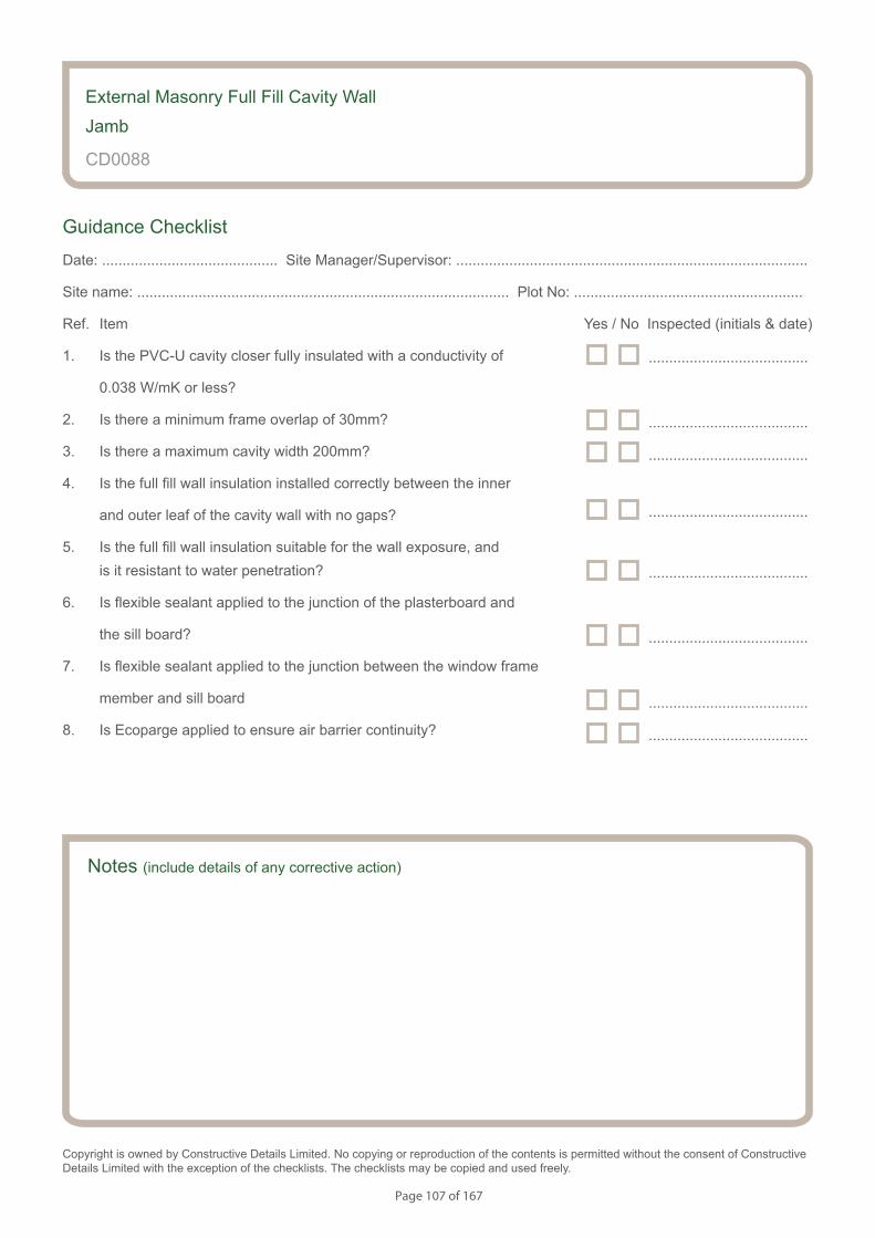
Page 107 of 167
Notes (include details of any corrective action)
External Masonry Full Fill Cavity Wall
Jamb
CD0088
Guidance Checklist
Date: ........................................... Site Manager/Supervisor: ......................................................................................
Site name: ........................................................................................... Plot No: ........................................................
Ref. Item Yes / No Inspected (initials & date)
1. Is the PVC-U cavity closer fully insulated with a conductivity of
0.038 W/mK or less?
2. Is there a minimum frame overlap of 30mm?
3. Is there a maximum cavity width 200mm?
4. Is the full fill wall insulation installed correctly between the inner
and outer leaf of the cavity wall with no gaps?
5. Is the full fill wall insulation suitable for the wall exposure, and is it resistant to water penetration?
6. Is flexible sealant applied to the junction of the plasterboard and
the sill board?
7. Is flexible sealant applied to the junction between the window frame
member and sill board
8. Is Ecoparge applied to ensure air barrier continuity?
Copyright is owned by Constructive Details Limited. No copying or reproduction of the contents is permitted without the consent of Constructive Details Limited with the exception of the checklists. The checklists may be copied and used freely.
.......................................
.......................................
.......................................
.......................................
.......................................
.......................................
.......................................
.......................................
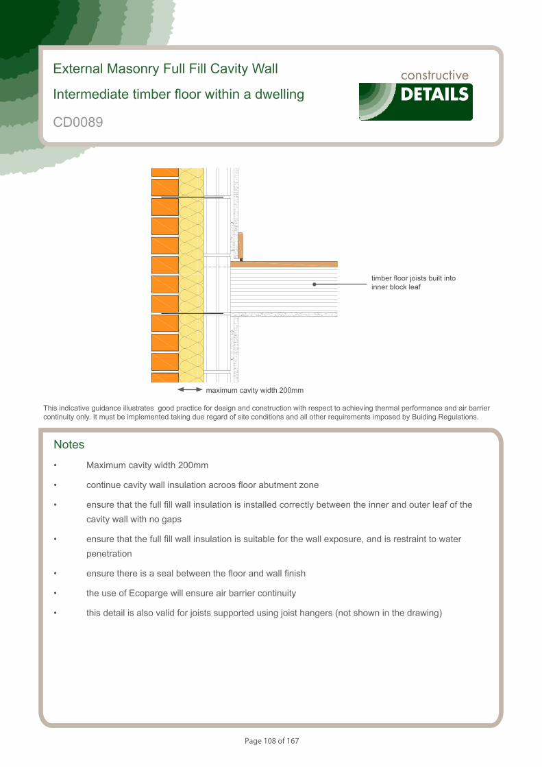
Page 108 of 167
Notes
• Maximum cavity width 200mm
• continue cavity wall insulation acroos floor abutment zone
• ensure that the full fill wall insulation is installed correctly between the inner and outer leaf of the cavity wall with no gaps
• ensure that the full fill wall insulation is suitable for the wall exposure, and is restraint to water penetration
• ensure there is a seal between the floor and wall finish
• the use of Ecoparge will ensure air barrier continuity
• this detail is also valid for joists supported using joist hangers (not shown in the drawing)
External Masonry Full Fill Cavity Wall
Intermediate timber floor within a dwelling
CD0089
This indicative guidance illustrates good practice for design and construction with respect to achieving thermal performance and air barrier continuity only. It must be implemented taking due regard of site conditions and all other requirements imposed by Buiding Regulations.
maximum cavity width 200mm
timber floor joists built into inner block leaf
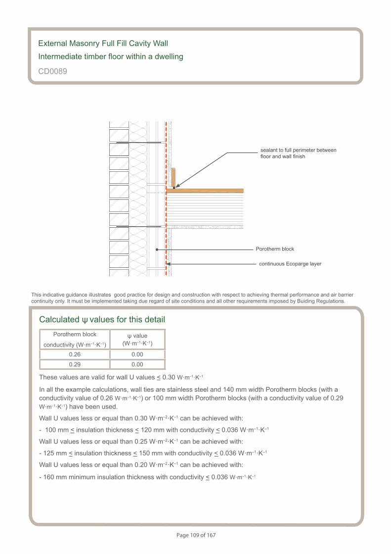
Page 109 of 167
Calculated ψ values for this detailPorotherm block
conductivity (W·m–1·K–1)ψ value
(W·m–1·K–1)
0.26 0.00
0.29 0.00
These values are valid for wall U values < 0.30 W·m–1·K–1
In all the example calculations, wall ties are stainless steel and 140 mm width Porotherm blocks (with a conductivity value of 0.26 W·m–1·K–1) or 100 mm width Porotherm blocks (with a conductivity value of 0.29 W·m–1·K–1) have been used.
Wall U values less or equal than 0.30 W·m–2·K–1 can be achieved with:
- 100 mm < insulation thickness < 120 mm with conductivity < 0.036 W·m–1·K–1
Wall U values less or equal than 0.25 W·m–2·K–1 can be achieved with:
- 125 mm < insulation thickness < 150 mm with conductivity < 0.036 W·m–1·K–1
Wall U values less or equal than 0.20 W·m–2·K–1 can be achieved with:
- 160 mm minimum insulation thickness with conductivity < 0.036 W·m–1·K–1
External Masonry Full Fill Cavity Wall
Intermediate timber floor within a dwelling
CD0089
sealant to full perimeter between floor and wall finish
This indicative guidance illustrates good practice for design and construction with respect to achieving thermal performance and air barrier continuity only. It must be implemented taking due regard of site conditions and all other requirements imposed by Buiding Regulations.
continuous Ecoparge layer
Porotherm block
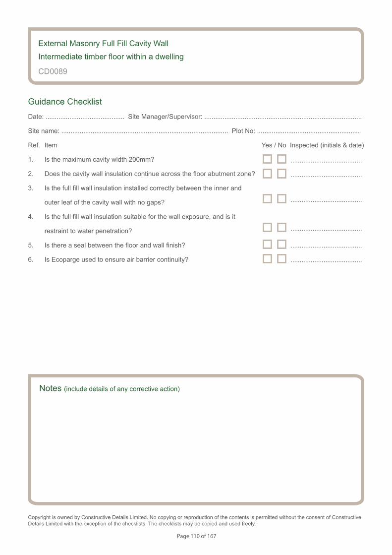
Page 110 of 167
Notes (include details of any corrective action)
External Masonry Full Fill Cavity Wall
Intermediate timber floor within a dwelling
CD0089
Guidance Checklist
Date: ........................................... Site Manager/Supervisor: ......................................................................................
Site name: ........................................................................................... Plot No: ........................................................
Ref. Item Yes / No Inspected (initials & date)
1. Is the maximum cavity width 200mm?
2. Does the cavity wall insulation continue across the floor abutment zone?
3. Is the full fill wall insulation installed correctly between the inner and
outer leaf of the cavity wall with no gaps?
4. Is the full fill wall insulation suitable for the wall exposure, and is it
restraint to water penetration?
5. Is there a seal between the floor and wall finish?
6. Is Ecoparge used to ensure air barrier continuity?
Copyright is owned by Constructive Details Limited. No copying or reproduction of the contents is permitted without the consent of Constructive Details Limited with the exception of the checklists. The checklists may be copied and used freely.
.......................................
.......................................
.......................................
.......................................
.......................................
.......................................
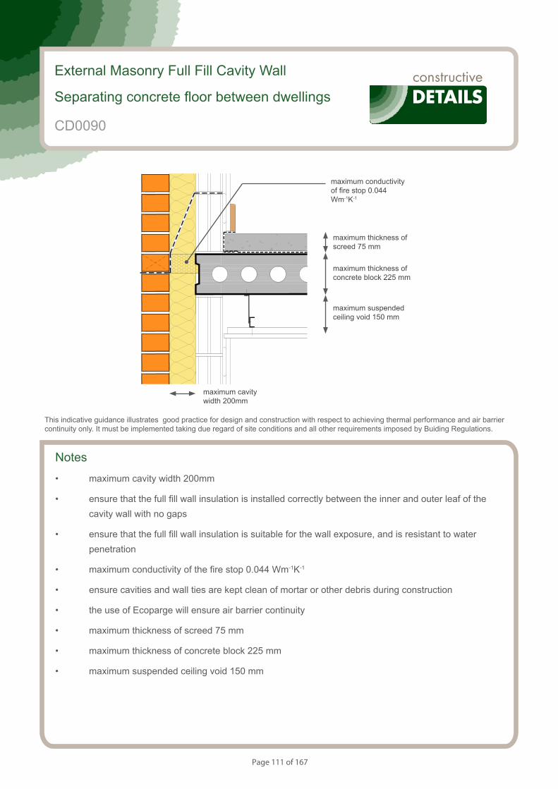
Page 111 of 167
Notes
• maximum cavity width 200mm
• ensure that the full fill wall insulation is installed correctly between the inner and outer leaf of the cavity wall with no gaps
• ensure that the full fill wall insulation is suitable for the wall exposure, and is resistant to water penetration
• maximum conductivity of the fire stop 0.044 Wm-1K-1
• ensure cavities and wall ties are kept clean of mortar or other debris during construction
• the use of Ecoparge will ensure air barrier continuity
• maximum thickness of screed 75 mm
• maximum thickness of concrete block 225 mm
• maximum suspended ceiling void 150 mm
External Masonry Full Fill Cavity Wall
Separating concrete floor between dwellings
CD0090
This indicative guidance illustrates good practice for design and construction with respect to achieving thermal performance and air barrier continuity only. It must be implemented taking due regard of site conditions and all other requirements imposed by Buiding Regulations.
maximum cavity width 200mm
maximum suspended ceiling void 150 mm
maximum thickness of concrete block 225 mm
maximum thickness of screed 75 mm
maximum conductivity of fire stop 0.044 Wm-1K-1

Page 112 of 167
Calculated ψ values for this detailPorotherm
block
conductivity
(W·m–1·K–1)
Wall U value less or equal than
0.20 W·m–2·K–1
Wall U value between
0.21 and 0.25 W·m–2·K–1
Wall U value between
0.26 and 0.30 W·m–2·K–1
ψ value (W·m–1·K–1)
Temperaturefactor
ψ value (W·m–1·K–1)
Temperaturefactor
ψ value (W·m–1·K–1)
Temperaturefactor
0.26 0.063 0.965 0.080 0.96 0.097 0.95
0.29 0.061 0.965 0.077 0.96 0.092 0.95
In all the example calculations, wall ties are stainless steel and 140 mm width Porotherm blocks (with a conductivity value of 0.26 W·m–1·K–1) or 100 mm width Porotherm blocks (with a conductivity value of 0.29 W·m–1·K–1) have been used.
Wall U values less or equal than 0.30 W·m–2·K–1 can be achieved with:
- 100 mm < insulation thickness < 120 mm with conductivity < 0.036 W·m–1·K–1
Wall U values less or equal than 0.25 W·m–2·K–1 can be achieved with:
- 125 mm < insulation thickness < 150 mm with conductivity < 0.036 W·m–1·K–1
Wall U values less or equal than 0.20 W·m–2·K–1 can be achieved with:
- 160 mm minimum insulation thickness with conductivity < 0.036 W·m–1·K–1
External Masonry Full Fill Cavity Wall
Separating concrete floor between dwellings
CD0090
This indicative guidance illustrates good practice for design and construction with respect to achieving thermal performance and air barrier continuity only. It must be implemented taking due regard of site conditions and all other requirements imposed by Buiding Regulations.
continuous Ecoparge layer
Porotherm block
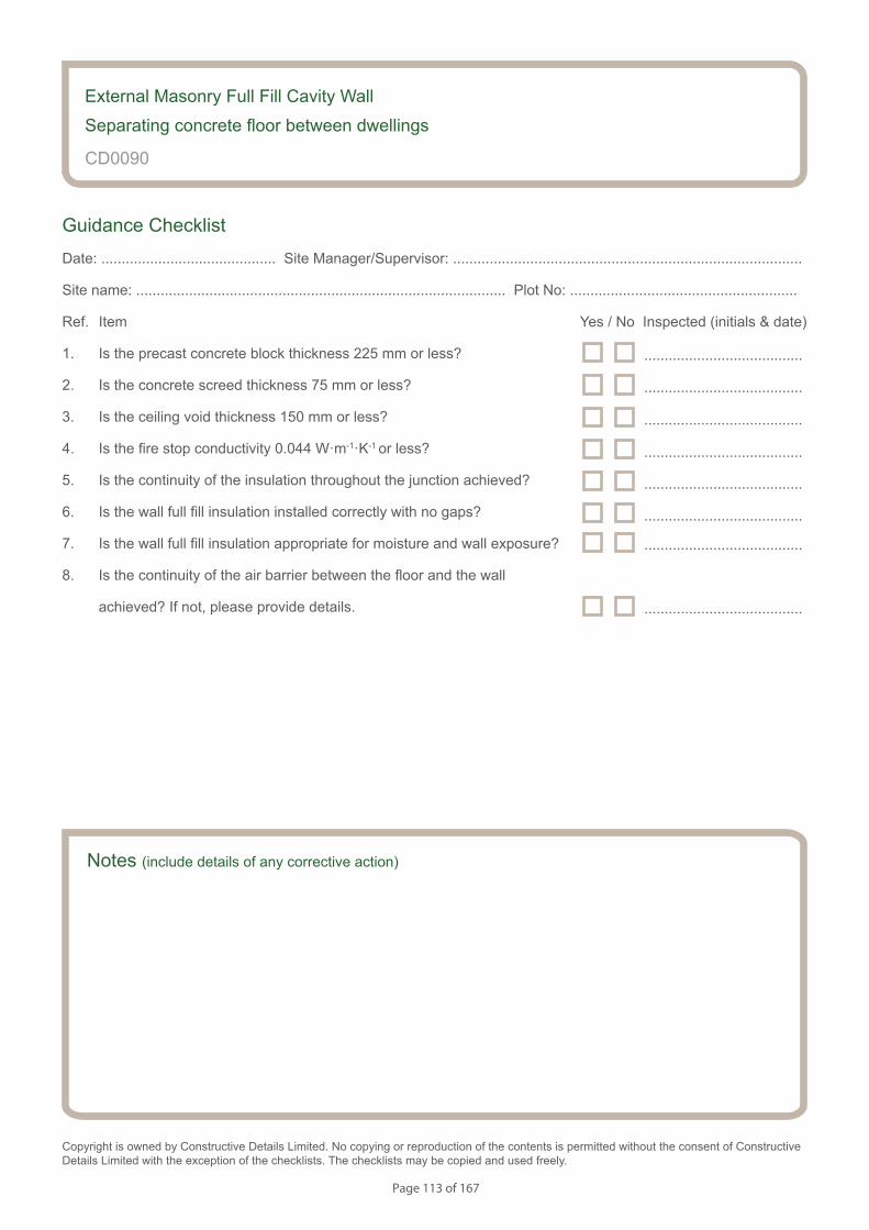
Page 113 of 167
Notes (include details of any corrective action)
CD0090
Guidance Checklist
Date: ........................................... Site Manager/Supervisor: ......................................................................................
Site name: ........................................................................................... Plot No: ........................................................
Ref. Item Yes / No Inspected (initials & date)
1. Is the precast concrete block thickness 225 mm or less?
2. Is the concrete screed thickness 75 mm or less?
3. Is the ceiling void thickness 150 mm or less?
4. Is the fire stop conductivity 0.044 W·m-1·K-1 or less?
5. Is the continuity of the insulation throughout the junction achieved?
6. Is the wall full fill insulation installed correctly with no gaps?
7. Is the wall full fill insulation appropriate for moisture and wall exposure?
8. Is the continuity of the air barrier between the floor and the wall
achieved? If not, please provide details.
Copyright is owned by Constructive Details Limited. No copying or reproduction of the contents is permitted without the consent of Constructive Details Limited with the exception of the checklists. The checklists may be copied and used freely.
.......................................
.......................................
.......................................
.......................................
.......................................
.......................................
External Masonry Full Fill Cavity Wall
Separating concrete floor between dwellings
.......................................
.......................................
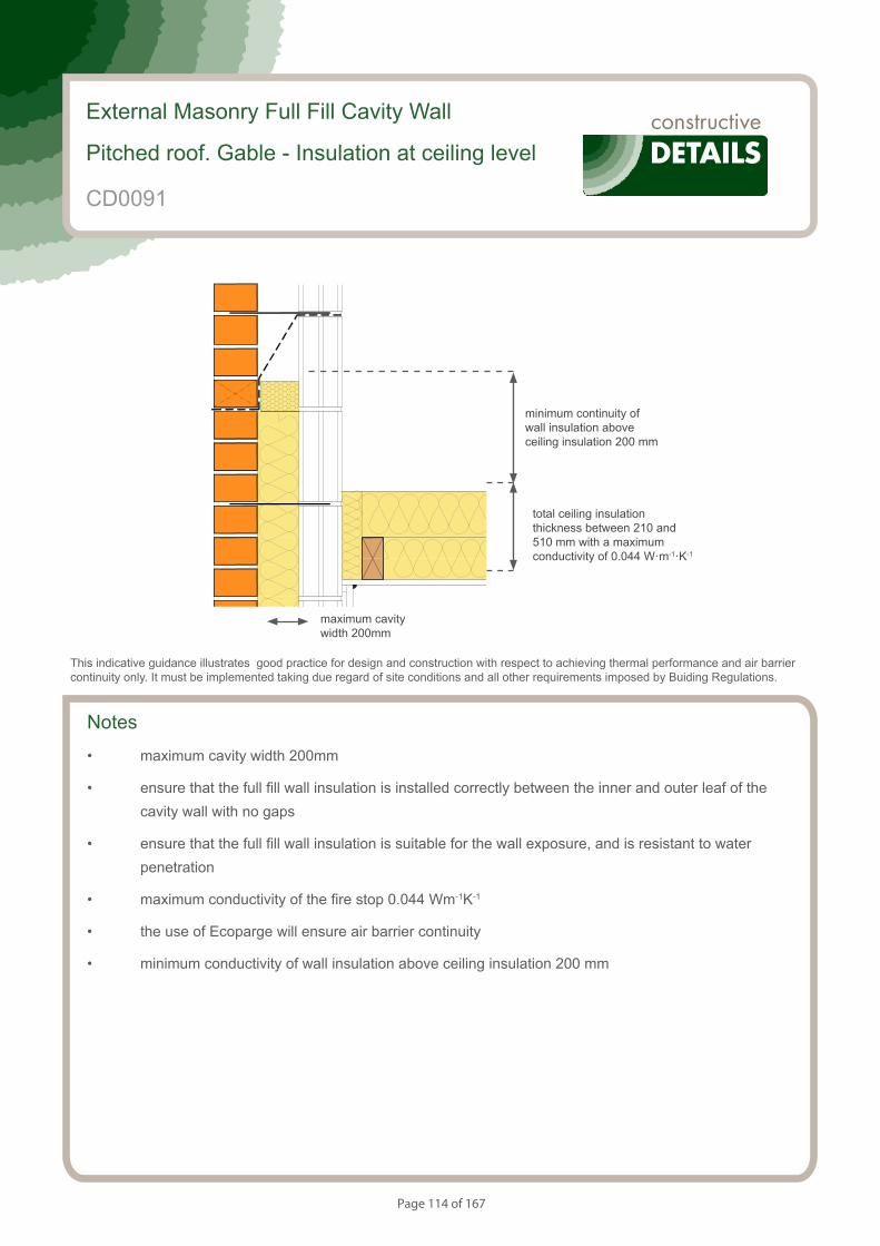
Page 114 of 167
Notes
• maximum cavity width 200mm
• ensure that the full fill wall insulation is installed correctly between the inner and outer leaf of the cavity wall with no gaps
• ensure that the full fill wall insulation is suitable for the wall exposure, and is resistant to water penetration
• maximum conductivity of the fire stop 0.044 Wm-1K-1
• the use of Ecoparge will ensure air barrier continuity
• minimum conductivity of wall insulation above ceiling insulation 200 mm
External Masonry Full Fill Cavity Wall
Pitched roof. Gable - Insulation at ceiling level
CD0091
This indicative guidance illustrates good practice for design and construction with respect to achieving thermal performance and air barrier continuity only. It must be implemented taking due regard of site conditions and all other requirements imposed by Buiding Regulations.
maximum cavity width 200mm
minimum continuity of wall insulation above ceiling insulation 200 mm
total ceiling insulation thickness between 210 and 510 mm with a maximum conductivity of 0.044 W·m-1·K-1
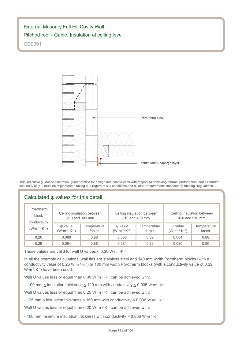
Page 115 of 167
Calculated ψ values for this detail
Porotherm
block
conductivity
(W·m–1·K–1)
Ceiling insulation between 210 and 309 mm
Ceiling insulation between 310 and 409 mm
Ceiling insulation between410 and 510 mm
ψ value (W·m–1·K–1)
Temperaturefactor
ψ value (W·m–1·K–1)
Temperaturefactor
ψ value (W·m–1·K–1)
Temperaturefactor
0.26 0.089 0.88 0.085 0.89 0.084 0.88
0.29 0.084 0.88 0.081 0.89 0.080 0.90
These values are valid for wall U values < 0.30 W·m–1·K–1
In all the example calculations, wall ties are stainless steel and 140 mm width Porotherm blocks (with a conductivity value of 0.26 W·m–1·K–1) or 100 mm width Porotherm blocks (with a conductivity value of 0.29 W·m–1·K–1) have been used.
Wall U values less or equal than 0.30 W·m–2·K–1 can be achieved with:
- 100 mm < insulation thickness < 120 mm with conductivity < 0.036 W·m–1·K–1
Wall U values less or equal than 0.25 W·m–2·K–1 can be achieved with:
- 125 mm < insulation thickness < 150 mm with conductivity < 0.036 W·m–1·K–1
Wall U values less or equal than 0.20 W·m–2·K–1 can be achieved with:
- 160 mm minimum insulation thickness with conductivity < 0.036 W·m–1·K–1
External Masonry Full Fill Cavity Wall
Pitched roof - Gable. Insulation at ceiling level
CD0091
This indicative guidance illustrates good practice for design and construction with respect to achieving thermal performance and air barrier continuity only. It must be implemented taking due regard of site conditions and all other requirements imposed by Buiding Regulations.
continuous Ecoparge layer
Porotherm block

Page 116 of 167
Notes (include details of any corrective action)
CD0091
Guidance Checklist
Date: ........................................... Site Manager/Supervisor: ......................................................................................
Site name: ........................................................................................... Plot No: ........................................................
Ref. Item Yes / No Inspected (initials & date)
1. Is the ceiling insulation thickness between 210 and 510 mm
and has a maximum conductivity of 0.044 W·m-1·K-1?
2. Is the gap between the first joint and the gable wall fully insulated?
3. Is the full fill insulation continued to at least 200 mm above the top
of the ceiling insulation?
5. If a cavity tray was used, does the full fill inulation fit tightly against
the cavity tray, with no gaps?
6. Is the wall full fill insulation installed correctly with no gaps?
7. Is the wall full fill insulation appropriate for moisture and wall exposure?
8. Is the continuity of the air barrier achieved? If not, please provide
details.
Copyright is owned by Constructive Details Limited. No copying or reproduction of the contents is permitted without the consent of Constructive Details Limited with the exception of the checklists. The checklists may be copied and used freely.
.......................................
.......................................
.......................................
.......................................
.......................................
.......................................
.......................................
External Masonry Full Fill Cavity Wall
Pitched roof - Gable. Insulation at ceiling level
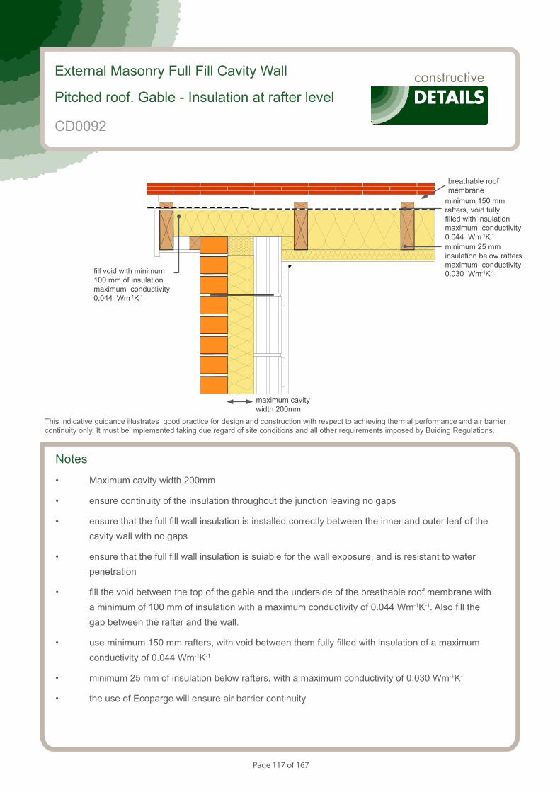
Page 117 of 167
Notes
• Maximum cavity width 200mm
• ensure continuity of the insulation throughout the junction leaving no gaps
• ensure that the full fill wall insulation is installed correctly between the inner and outer leaf of the cavity wall with no gaps
• ensure that the full fill wall insulation is suiable for the wall exposure, and is resistant to water penetration
• fill the void between the top of the gable and the underside of the breathable roof membrane with a minimum of 100 mm of insulation with a maximum conductivity of 0.044 Wm-1K-1. Also fill the gap between the rafter and the wall.
• use minimum 150 mm rafters, with void between them fully filled with insulation of a maximum conductivity of 0.044 Wm-1K-1
• minimum 25 mm of insulation below rafters, with a maximum conductivity of 0.030 Wm-1K-1
• the use of Ecoparge will ensure air barrier continuity
External Masonry Full Fill Cavity Wall
Pitched roof. Gable - Insulation at rafter level
CD0092
This indicative guidance illustrates good practice for design and construction with respect to achieving thermal performance and air barrier continuity only. It must be implemented taking due regard of site conditions and all other requirements imposed by Buiding Regulations.
maximum cavity width 200mm
minimum 150 mm rafters, void fully filled with insulation maximum conductivity 0.044 Wm-1K-1
breathable roof membrane
fill void with minimum 100 mm of insulation maximum conductivity 0.044 Wm-1K-1
minimum 25 mm insulation below rafters maximum conductivity 0.030 Wm-1K-1
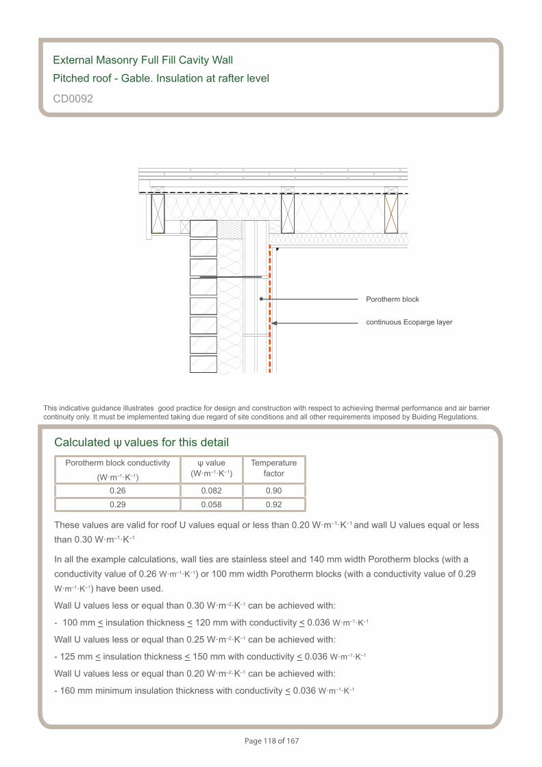
Page 118 of 167
Calculated ψ values for this detailPorotherm block conductivity
(W·m–1·K–1)
ψ value (W·m–1·K–1)
Temperaturefactor
0.26 0.082 0.90
0.29 0.058 0.92
These values are valid for roof U values equal or less than 0.20 W·m–1·K–1 and wall U values equal or less than 0.30 W·m–1·K–1
In all the example calculations, wall ties are stainless steel and 140 mm width Porotherm blocks (with a conductivity value of 0.26 W·m–1·K–1) or 100 mm width Porotherm blocks (with a conductivity value of 0.29 W·m–1·K–1) have been used.
Wall U values less or equal than 0.30 W·m–2·K–1 can be achieved with:
- 100 mm < insulation thickness < 120 mm with conductivity < 0.036 W·m–1·K–1
Wall U values less or equal than 0.25 W·m–2·K–1 can be achieved with:
- 125 mm < insulation thickness < 150 mm with conductivity < 0.036 W·m–1·K–1
Wall U values less or equal than 0.20 W·m–2·K–1 can be achieved with:
- 160 mm minimum insulation thickness with conductivity < 0.036 W·m–1·K–1
External Masonry Full Fill Cavity Wall
Pitched roof - Gable. Insulation at rafter level
CD0092
This indicative guidance illustrates good practice for design and construction with respect to achieving thermal performance and air barrier continuity only. It must be implemented taking due regard of site conditions and all other requirements imposed by Buiding Regulations.
continuous Ecoparge layer
Porotherm block
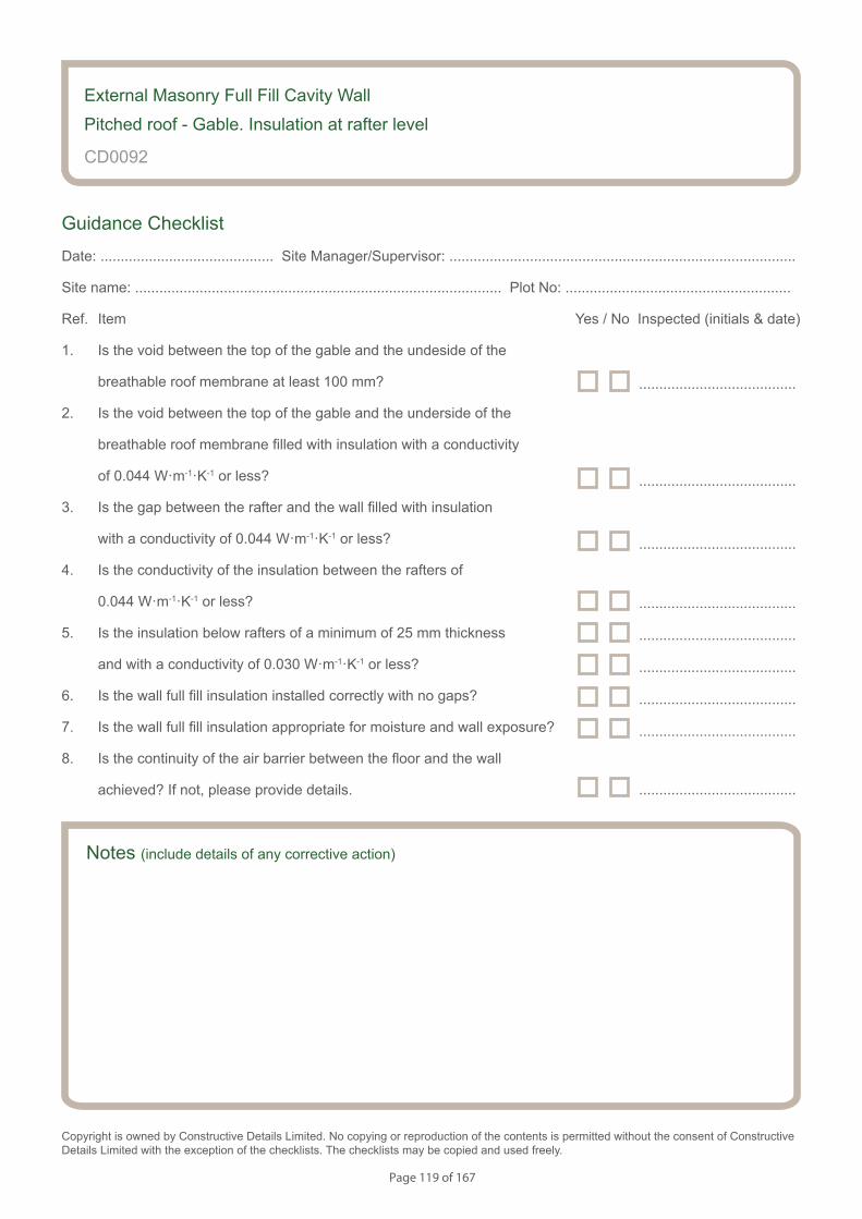
Page 119 of 167
Notes (include details of any corrective action)
CD0092
Guidance Checklist
Date: ........................................... Site Manager/Supervisor: ......................................................................................
Site name: ........................................................................................... Plot No: ........................................................
Ref. Item Yes / No Inspected (initials & date)
1. Is the void between the top of the gable and the undeside of the
breathable roof membrane at least 100 mm?
2. Is the void between the top of the gable and the underside of the
breathable roof membrane filled with insulation with a conductivity
of 0.044 W·m-1·K-1 or less?
3. Is the gap between the rafter and the wall filled with insulation
with a conductivity of 0.044 W·m-1·K-1 or less?
4. Is the conductivity of the insulation between the rafters of
0.044 W·m-1·K-1 or less?
5. Is the insulation below rafters of a minimum of 25 mm thickness
and with a conductivity of 0.030 W·m-1·K-1 or less?
6. Is the wall full fill insulation installed correctly with no gaps?
7. Is the wall full fill insulation appropriate for moisture and wall exposure?
8. Is the continuity of the air barrier between the floor and the wall
achieved? If not, please provide details.
Copyright is owned by Constructive Details Limited. No copying or reproduction of the contents is permitted without the consent of Constructive Details Limited with the exception of the checklists. The checklists may be copied and used freely.
.......................................
.......................................
.......................................
.......................................
.......................................
.......................................
.......................................
External Masonry Full Fill Cavity Wall
Pitched roof - Gable. Insulation at rafter level
.......................................
.......................................
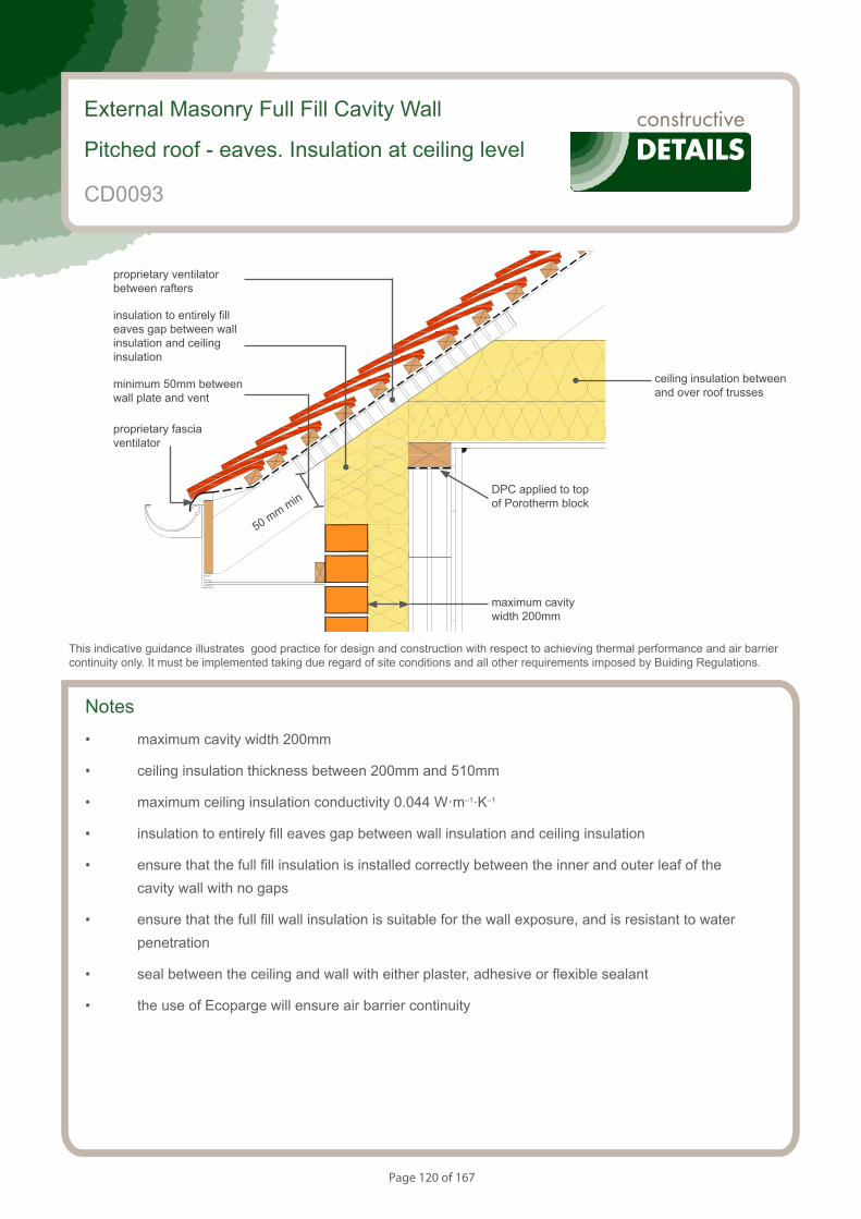
Page 120 of 167
S050426_CD0035
Pitched roof. Eaves - Insulation at ceiling level - Ventilated loft
External Masonry Full Fill Cavity Wall
Pitched roof - eaves. Insulation at ceiling level
This indicative guidance illustrates good practice for design and construction with respect to achieving thermal performance and air barrier continuity only. It must be implemented taking due regard of site conditions and all other requirements imposed by Buiding Regulations.
maximum cavity width 200mm
ceiling insulation between and over roof trusses
proprietary ventilator between rafters
insulation to entirely fill eaves gap between wall insulation and ceiling insulation
minimum 50mm between wall plate and vent
proprietary fascia ventilator
50 mm min
Notes
• maximum cavity width 200mm
• ceiling insulation thickness between 200mm and 510mm
• maximum ceiling insulation conductivity 0.044 W·m–1·K–1
• insulation to entirely fill eaves gap between wall insulation and ceiling insulation
• ensure that the full fill insulation is installed correctly between the inner and outer leaf of the cavity wall with no gaps
• ensure that the full fill wall insulation is suitable for the wall exposure, and is resistant to water penetration
• seal between the ceiling and wall with either plaster, adhesive or flexible sealant
• the use of Ecoparge will ensure air barrier continuity
CD0093
DPC applied to top of Porotherm block
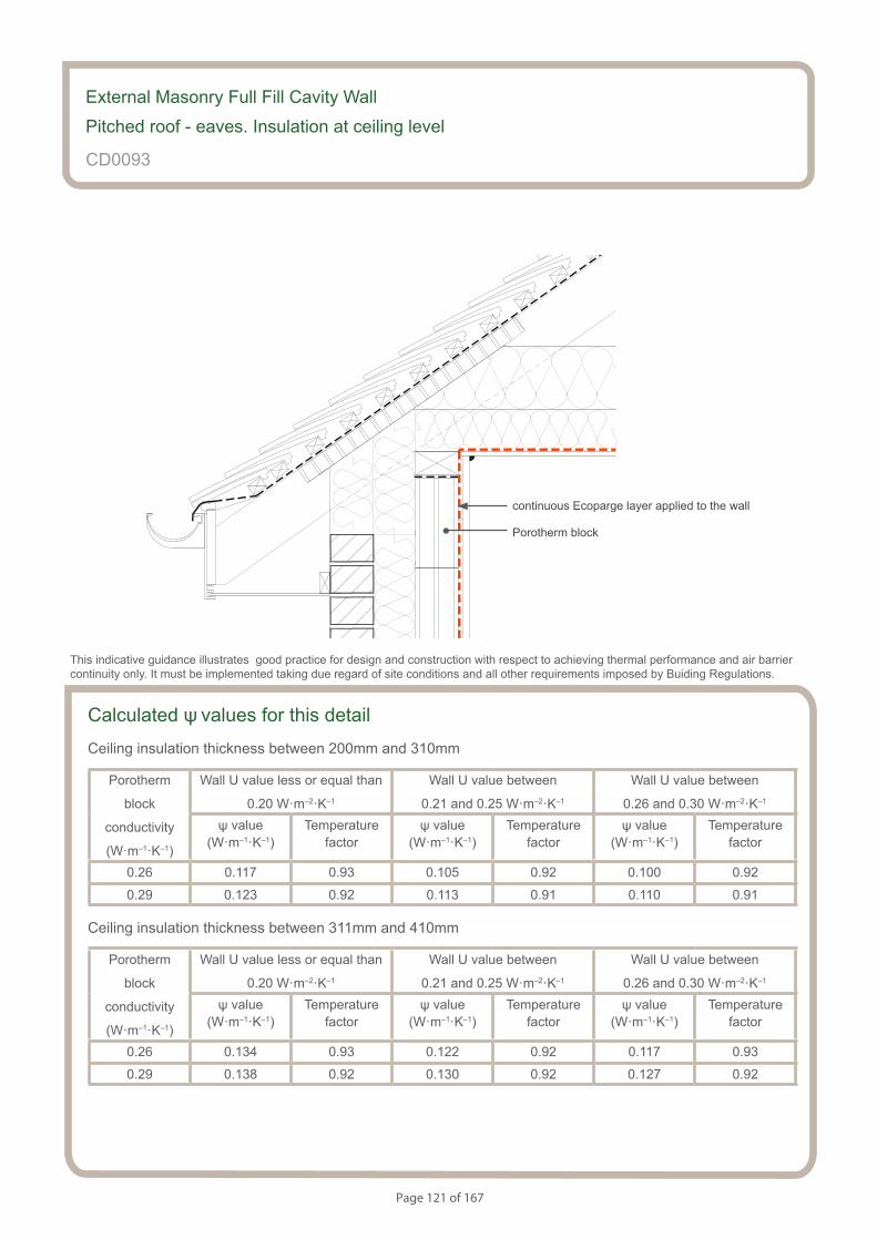
Page 121 of 167
S050426_CD0035
Pitched roof. Eaves - Insulation at ceiling level - Ventilated loft
Calculated ψ values for this detail
Ceiling insulation thickness between 200mm and 310mm
Porotherm
block
conductivity
(W·m–1·K–1)
Wall U value less or equal than
0.20 W·m–2·K–1
Wall U value between
0.21 and 0.25 W·m–2·K–1
Wall U value between
0.26 and 0.30 W·m–2·K–1
ψ value (W·m–1·K–1)
Temperaturefactor
ψ value (W·m–1·K–1)
Temperaturefactor
ψ value (W·m–1·K–1)
Temperaturefactor
0.26 0.117 0.93 0.105 0.92 0.100 0.92
0.29 0.123 0.92 0.113 0.91 0.110 0.91
Ceiling insulation thickness between 311mm and 410mm
Porotherm
block
conductivity
(W·m–1·K–1)
Wall U value less or equal than
0.20 W·m–2·K–1
Wall U value between
0.21 and 0.25 W·m–2·K–1
Wall U value between
0.26 and 0.30 W·m–2·K–1
ψ value (W·m–1·K–1)
Temperaturefactor
ψ value (W·m–1·K–1)
Temperaturefactor
ψ value (W·m–1·K–1)
Temperaturefactor
0.26 0.134 0.93 0.122 0.92 0.117 0.93
0.29 0.138 0.92 0.130 0.92 0.127 0.92
External Masonry Full Fill Cavity Wall
Pitched roof - eaves. Insulation at ceiling level
CD0093
This indicative guidance illustrates good practice for design and construction with respect to achieving thermal performance and air barrier continuity only. It must be implemented taking due regard of site conditions and all other requirements imposed by Buiding Regulations.
Porotherm block
continuous Ecoparge layer applied to the wall
Page 122 of 167
External Masonry Full Fill Cavity Wall
Pitched roof - eaves. Insulation at ceiling level
CD0093
Ceiling insulation thickness between 411mm and 510mm
Porotherm
block
conductivity
(W·m–1·K–1)
Wall U value less or equal than
0.20 W·m–2·K–1
Wall U value between
0.21 and 0.25 W·m–2·K–1
Wall U value between
0.26 and 0.30 W·m–2·K–1
ψ value (W·m–1·K–1)
Temperaturefactor
ψ value (W·m–1·K–1)
Temperaturefactor
ψ value (W·m–1·K–1)
Temperaturefactor
0.26 0.149 0.93 0.136 0.93 0.132 0.93
0.29 0.156 0.92 0.145 0.92 0.142 0.92
In all the example calculations, wall ties are stainless steel and 140 mm width Porotherm blocks (with a conductivity value of 0.26 W·m–1·K–1) or 100 mm width Porotherm blocks (with a conductivity value of 0.29 W·m–1·K–1) have been used.
Wall U values less or equal than 0.30 W·m–2·K–1 can be achieved with:
- 100 mm < insulation thickness < 120 mm with conductivity < 0.036 W·m–1·K–1
Wall U values less or equal than 0.25 W·m–2·K–1 can be achieved with:
- 125 mm < insulation thickness < 150 mm with conductivity < 0.036 W·m–1·K–1
Wall U values less or equal than 0.20 W·m–2·K–1 can be achieved with:
- 160 mm minimum insulation thickness with conductivity < 0.036 W·m–1·K–1

Page 123 of 167
Notes (include details of any corrective action)
CD0093
Guidance Checklist
Date: ........................................... Site Manager/Supervisor: ......................................................................................
Site name: ........................................................................................... Plot No: ........................................................
Ref. Item Yes / No Inspected (initials & date)
1. Is the ceiling insulation thickness between 200 and 510 mm?
2. Is the ceiling insulation conductivity 0.044 W·m-1·K-1 or less?
3. Is there a minimum 50mm gap between the ventilator and the
wall plate filled with insulation?
4. Does the insulation entirely fill the eaves gap between the wall insulation
and the ceiling insulation?
5. Is the wall full fill insulation installed correctly with no gaps?
6. Is the wall full fill insulation appropriate for moisture and wall exposure?
7. Is the continuity of the air barrier between the floor and the wall
achieved? If not, please provide details.
Copyright is owned by Constructive Details Limited. No copying or reproduction of the contents is permitted without the consent of Constructive Details Limited with the exception of the checklists. The checklists may be copied and used freely.
.......................................
.......................................
.......................................
.......................................
.......................................
.......................................
External Masonry Full Fill Cavity Wall
Pitched roof - eaves. Insulation at ceiling level
.......................................

Page 124 of 167
S154083_CD0036
Pitched roof. Eaves - Insulation at rafter level - Unventilated rafter void
This indicative guidance illustrates good practice for design and construction with respect to achieving thermal performance and air barrier continuity only. It must be implemented taking due regard of site conditions and all other requirements imposed by Buiding Regulations.
maximum cavity width 200mm
insulation between rafters to sloping ceiling section
insulation to entirely fill eaves gap between wall insulation and ceiling insulation
Notes
• maximum cavity width 200mm
• minimum 50mm wall clear air cavity
• ceiling insulation thickness between 100mm and 410mm
• maximum ceiling insulation conductivity 0.044 W·m–1·K–1
• insulation to entirely fill eaves gap between wall insulation and ceiling insulation
• ensure that the full fill insulation is installed correctly between the inner and outer leaf of the cavity wall with no gaps
• ensure that the full fill wall insulation is suitable for the wall exposure, and is resistant to water penetration
• seal between the ceiling and wall with either plaster, adhesive or flexible sealant
• the use of Ecoparge will ensure air barrier continuity
External Masonry Full Fill Cavity Wall
Pitched roof - eaves. Insulation at rafter level
rafter insulation thickness
CD0094
DPC applied to top of Porotherm block
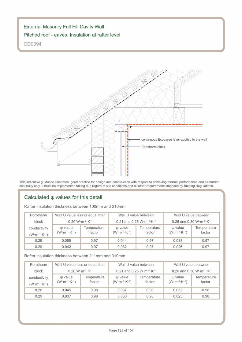
Page 125 of 167
S154083_CD0036
Pitched roof. Eaves - Insulation at rafter level - Unventilated rafter void
CD0094
This indicative guidance illustrates good practice for design and construction with respect to achieving thermal performance and air barrier continuity only. It must be implemented taking due regard of site conditions and all other requirements imposed by Buiding Regulations.
continuous Ecoparge layer applied to the wall
Porotherm block
Calculated ψ values for this detail
Rafter insulation thickness between 100mm and 210mm
Porotherm
block
conductivity
(W·m–1·K–1)
Wall U value less or equal than
0.20 W·m–2·K–1
Wall U value between
0.21 and 0.25 W·m–2·K–1
Wall U value between
0.26 and 0.30 W·m–2·K–1
ψ value (W·m–1·K–1)
Temperaturefactor
ψ value (W·m–1·K–1)
Temperaturefactor
ψ value (W·m–1·K–1)
Temperaturefactor
0.26 0.055 0.97 0.044 0.97 0.038 0.97
0.29 0.042 0.97 0.032 0.97 0.026 0.97
Rafter insulation thickness between 211mm and 310mm
Porotherm
block
conductivity
(W·m–1·K–1)
Wall U value less or equal than
0.20 W·m–2·K–1
Wall U value between
0.21 and 0.25 W·m–2·K–1
Wall U value between
0.26 and 0.30 W·m–2·K–1
ψ value (W·m–1·K–1)
Temperaturefactor
ψ value (W·m–1·K–1)
Temperaturefactor
ψ value (W·m–1·K–1)
Temperaturefactor
0.26 0.045 0.98 0.037 0.98 0.032 0.98
0.29 0.037 0.98 0.030 0.98 0.025 0.98
External Masonry Full Fill Cavity Wall
Pitched roof - eaves. Insulation at rafter level
Page 126 of 167
CD0094
External Masonry Full Fill Cavity Wall
Pitched roof - eaves. Insulation at rafter level
Rafter insulation thickness between 311mm and 410mm
Porotherm
block
conductivity
(W·m–1·K–1)
Wall U value less or equal than
0.20 W·m–2·K–1
Wall U value between
0.21 and 0.25 W·m–2·K–1
Wall U value between
0.26 and 0.30 W·m–2·K–1
ψ value (W·m–1·K–1)
Temperaturefactor
ψ value (W·m–1·K–1)
Temperaturefactor
ψ value (W·m–1·K–1)
Temperaturefactor
0.26 0.041 0.98 0.035 0.98 0.031 0.98
0.29 0.036 0.98 0.032 0.98 0.027 0.98
In all the example calculations, wall ties are stainless steel and 140 mm width Porotherm blocks (with a conductivity value of 0.26 W·m–1·K–1) or 100 mm width Porotherm blocks (with a conductivity value of 0.29 W·m–1·K–1) have been used.
Wall U values less or equal than 0.30 W·m–2·K–1 can be achieved with:
- 100 mm < insulation thickness < 120 mm with conductivity < 0.036 W·m–1·K–1
Wall U values less or equal than 0.25 W·m–2·K–1 can be achieved with:
- 125 mm < insulation thickness < 150 mm with conductivity < 0.036 W·m–1·K–1
Wall U values less or equal than 0.20 W·m–2·K–1 can be achieved with:
- 160 mm minimum insulation thickness with conductivity < 0.036 W·m–1·K–1
Page 127 of 167
Notes (include details of any corrective action)
CD0094
Guidance Checklist
Date: ........................................... Site Manager/Supervisor: ......................................................................................
Site name: ........................................................................................... Plot No: ........................................................
Ref. Item Yes / No Inspected (initials & date)
1. Is the ceiling insulation thickness between 100 and 410 mm?
2. Is the ceiling insulation conductivity 0.044 W·m-1·K-1 or less?
3. Is there a minimum 50mm gap between the ventilator and the
wall plate filled with insulation?
4. Does the insulation entirely fill the eaves gap between the wall insulation
and the ceiling insulation?
5. Is the wall full fill insulation installed correctly with no gaps?
6. Is the wall full fill insulation appropriate for moisture and wall exposure?
7. Is the continuity of the air barrier between the floor and the wall
achieved? If not, please provide details.
Copyright is owned by Constructive Details Limited. No copying or reproduction of the contents is permitted without the consent of Constructive Details Limited with the exception of the checklists. The checklists may be copied and used freely.
.......................................
.......................................
.......................................
.......................................
.......................................
.......................................
External Masonry Full Fill Cavity Wall
Pitched roof - eaves. Insulation at rafter level
.......................................

Page 128 of 167
Notes
• Maximum cavity width 200mm
• ensure that the full fill insulation is installed correctly between the inner and outer leaf of the cavity wall with no gaps
• ensure that the full fill wall insulation is suitable for the wall exposure, and is resistant to water penetration
• the use of Ecoparge will ensure air barrier continuity
External Masonry Full Fill Cavity Wall
Normal Corner
CD0095
This indicative guidance illustrates good practice for design and construction with respect to achieving thermal performance and air barrier continuity only. It must be implemented taking due regard of site conditions and all other requirements imposed by Buiding Regulations.
maximum cavity width 200mm
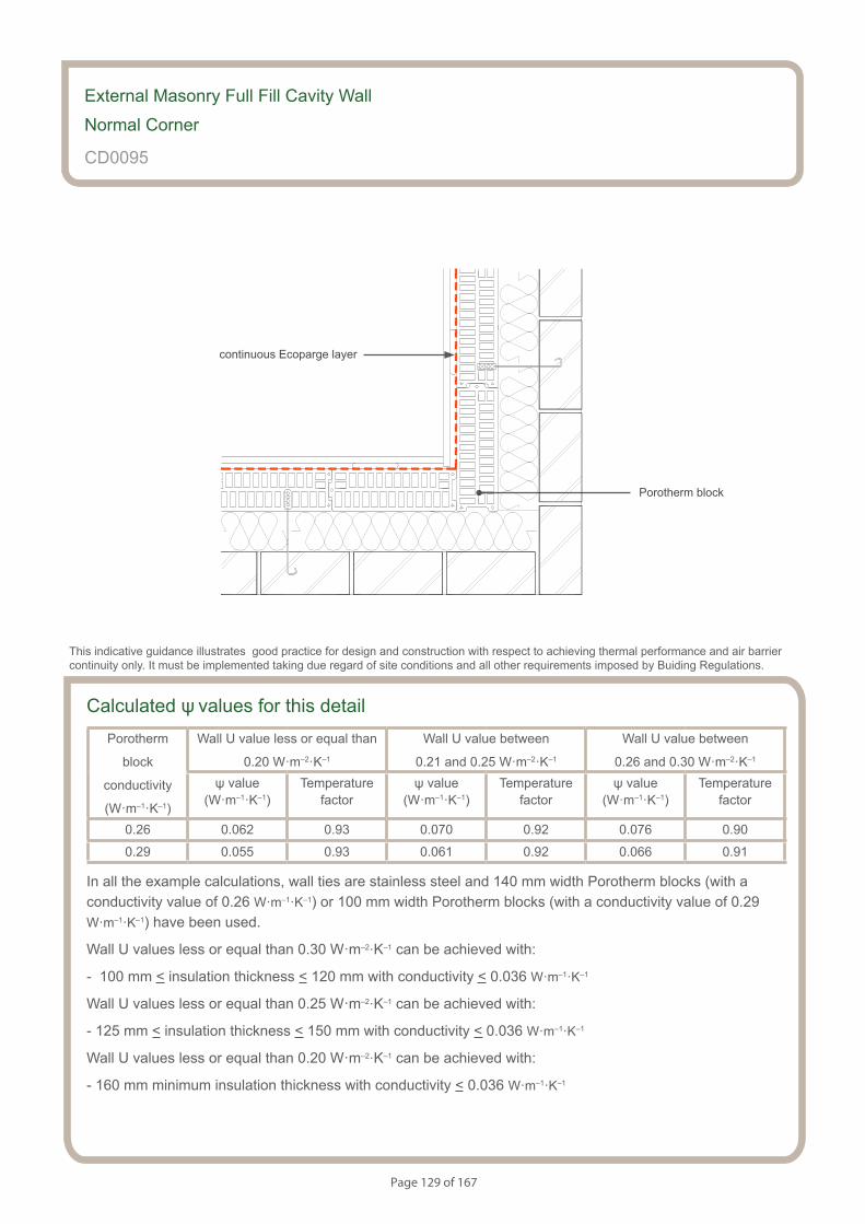
Page 129 of 167
Calculated ψ values for this detailPorotherm
block
conductivity
(W·m–1·K–1)
Wall U value less or equal than
0.20 W·m–2·K–1
Wall U value between
0.21 and 0.25 W·m–2·K–1
Wall U value between
0.26 and 0.30 W·m–2·K–1
ψ value (W·m–1·K–1)
Temperaturefactor
ψ value (W·m–1·K–1)
Temperaturefactor
ψ value (W·m–1·K–1)
Temperaturefactor
0.26 0.062 0.93 0.070 0.92 0.076 0.90
0.29 0.055 0.93 0.061 0.92 0.066 0.91
In all the example calculations, wall ties are stainless steel and 140 mm width Porotherm blocks (with a conductivity value of 0.26 W·m–1·K–1) or 100 mm width Porotherm blocks (with a conductivity value of 0.29 W·m–1·K–1) have been used.
Wall U values less or equal than 0.30 W·m–2·K–1 can be achieved with:
- 100 mm < insulation thickness < 120 mm with conductivity < 0.036 W·m–1·K–1
Wall U values less or equal than 0.25 W·m–2·K–1 can be achieved with:
- 125 mm < insulation thickness < 150 mm with conductivity < 0.036 W·m–1·K–1
Wall U values less or equal than 0.20 W·m–2·K–1 can be achieved with:
- 160 mm minimum insulation thickness with conductivity < 0.036 W·m–1·K–1
External Masonry Full Fill Cavity Wall
Normal Corner
CD0095
This indicative guidance illustrates good practice for design and construction with respect to achieving thermal performance and air barrier continuity only. It must be implemented taking due regard of site conditions and all other requirements imposed by Buiding Regulations.
continuous Ecoparge layer
Porotherm block
Page 130 of 167
Notes (include details of any corrective action)
External Masonry Full Fill Cavity Wall
Normal Corner
CD0095
Copyright is owned by Constructive Details Limited. No copying or reproduction of the contents is permitted without the consent of Constructive Details Limited with the exception of the checklists. The checklists may be copied and used freely.
.......................................
.......................................
.......................................
.......................................
Guidance Checklist
Date: ........................................... Site Manager/Supervisor: ......................................................................................
Site name: ........................................................................................... Plot No: ........................................................
Ref. Item Yes / No Inspected (initials & date)
1. Is the maximum cavity width 200mm?
2. Is the full fill wall insulation installed correctly between the inner and
outer leaf of the cavity wall with no gaps?
3. Is the full fill wall insulation suitable for the wall exposure, and is it
resistant to water penetration?
8. Is Ecoparge used to ensure air barrier continuity?
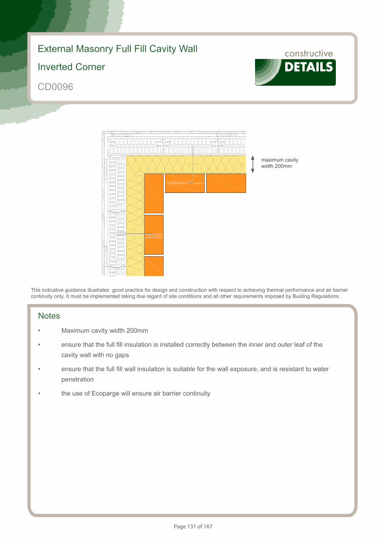
Page 131 of 167
Notes
• Maximum cavity width 200mm
• ensure that the full fill insulation is installed correctly between the inner and outer leaf of the cavity wall with no gaps
• ensure that the full fill wall insulation is suitable for the wall exposure, and is resistant to water penetration
• the use of Ecoparge will ensure air barrier continuity
External Masonry Full Fill Cavity Wall
Inverted Corner
This indicative guidance illustrates good practice for design and construction with respect to achieving thermal performance and air barrier continuity only. It must be implemented taking due regard of site conditions and all other requirements imposed by Buiding Regulations.
maximum cavity width 200mm
CD0096
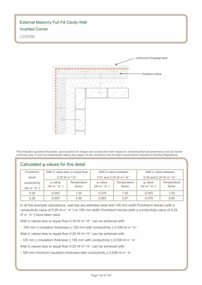
Page 132 of 167
Calculated ψ values for this detailPorotherm
block
conductivity
(W·m–1·K–1)
Wall U value less or equal than
0.20 W·m–2·K–1
Wall U value between
0.21 and 0.25 W·m–2·K–1
Wall U value between
0.26 and 0.30 W·m–2·K–1
ψ value (W·m–1·K–1)
Temperaturefactor
ψ value (W·m–1·K–1)
Temperaturefactor
ψ value (W·m–1·K–1)
Temperaturefactor
0.26 -0.053 1.00 -0.079 1.00 -0.093 1.00
0.29 -0.047 0.99 -0.067 0.97 -0.079 0.96
In all the example calculations, wall ties are stainless steel and 140 mm width Porotherm blocks (with a conductivity value of 0.26 W·m–1·K–1) or 100 mm width Porotherm blocks (with a conductivity value of 0.29 W·m–1·K–1) have been used.
Wall U values less or equal than 0.30 W·m–2·K–1 can be achieved with:
- 100 mm < insulation thickness < 120 mm with conductivity < 0.036 W·m–1·K–1
Wall U values less or equal than 0.25 W·m–2·K–1 can be achieved with:
- 125 mm < insulation thickness < 150 mm with conductivity < 0.036 W·m–1·K–1
Wall U values less or equal than 0.20 W·m–2·K–1 can be achieved with:
- 160 mm minimum insulation thickness with conductivity < 0.036 W·m–1·K–1
External Masonry Full Fill Cavity Wall
Inverted Corner
CD0096
This indicative guidance illustrates good practice for design and construction with respect to achieving thermal performance and air barrier continuity only. It must be implemented taking due regard of site conditions and all other requirements imposed by Buiding Regulations.
continuous Ecoparge layer
Porotherm block

Page 133 of 167
Notes (include details of any corrective action)
External Masonry Full Fill Cavity Wall
Inverted Corner
CD0096
Guidance Checklist
Date: ........................................... Site Manager/Supervisor: ......................................................................................
Site name: ........................................................................................... Plot No: ........................................................
Ref. Item Yes / No Inspected (initials & date)
1. Is the maximum cavity width 200mm?
2. Is the full fill wall insulation installed correctly between the inner and
outer leaf of the cavity wall with no gaps?
3. Is the full fill wall insulation suitable for the wall exposure, and is it
resistant to water penetration?
8. Is Ecoparge used to ensure air barrier continuity?
Copyright is owned by Constructive Details Limited. No copying or reproduction of the contents is permitted without the consent of Constructive Details Limited with the exception of the checklists. The checklists may be copied and used freely.
.......................................
.......................................
.......................................
.......................................
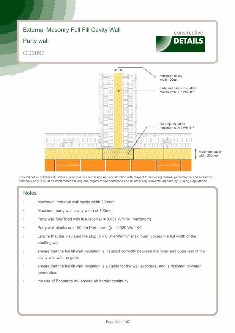
Page 134 of 167
Notes
• Maximum external wall cavity width 200mm
• Maximum party wall cavity width of 100mm
• Party wall fully filled with insulation (λ = 0.037 Wm-1K-1 maximum)
• Party wall blocks are 100mm Porotherm (λ = 0.029 Wm-1K-1)
• Ensure that the insulated fire stop (λ = 0.044 Wm-1K-1 maximum) covers the full width of the abutting wall
• ensure that the full fill wall insulation is installed correctly between the inner and outer leaf of the cavity wall with no gaps
• ensure that the full fill wall insulation is suitable for the wall exposure, and is resistant to water penetration
• the use of Ecoparge will ensure air barrier continuity
External Masonry Full Fill Cavity Wall
Party wall
This indicative guidance illustrates good practice for design and construction with respect to achieving thermal performance and air barrier continuity only. It must be implemented taking due regard of site conditions and all other requirements imposed by Buiding Regulations.
maximum cavity width 200mm
maximum cavity width 100mm
party wall cavity insulation maximum 0.037 Wm-1K-1
fire stop insulation maximum 0.044 Wm-1K-1
CD0097

Page 135 of 167
Calculated ψ values for this detailPorotherm
block
conductivity
(W·m–1·K–1)
Wall U value less or equal than
0.20 W·m–2·K–1
Wall U value between
0.21 and 0.25 W·m–2·K–1
Wall U value between
0.26 and 0.30 W·m–2·K–1
ψ value (W·m–1·K–1)
Temperaturefactor
ψ value (W·m–1·K–1)
Temperaturefactor
ψ value (W·m–1·K–1)
Temperaturefactor
0.26 0.054 0.94 0.063 0.93 0.067 0.92
0.29 0.055 0.94 0.064 0.92 0.072 0.91
In all the example calculations, wall ties are stainless steel and 140 mm width Porotherm blocks (with a conductivity value of 0.26 W·m–1·K–1) or 100 mm width Porotherm blocks (with a conductivity value of 0.29 W·m–1·K–1) have been used.
Wall U values less or equal than 0.30 W·m–1·K–1 can be achieved with:
- 100 mm < insulation thickness < 120 mm with conductivity < 0.036 W·m–1·K–1
Wall U values less or equal than 0.25 W·m–1·K–1 can be achieved with:
- 125 mm < insulation thickness < 150 mm with conductivity < 0.036 W·m–1·K–1
Wall U values less or equal than 0.20 W·m–1·K–1 can be achieved with:
- 160 mm minimum insulation thickness with conductivity < 0.036 W·m–1·K–1
External Masonry Full Fill Cavity Wall
Party wall
CD0097
This indicative guidance illustrates good practice for design and construction with respect to achieving thermal performance and air barrier continuity only. It must be implemented taking due regard of site conditions and all other requirements imposed by Buiding Regulations.
continuous Ecoparge layer
100mm Porotherm block (0.029 Wm-1K-1)
Page 136 of 167
Notes (include details of any corrective action)
External Masonry Full Fill Cavity Wall
Party wall
CD0097
Guidance Checklist
Date: ........................................... Site Manager/Supervisor: ......................................................................................
Site name: ........................................................................................... Plot No: ........................................................
Ref. Item Yes / No Inspected (initials & date)
1. Is the maximum external wall cavity width 200mm?
2. Is the maximum party wall cavity width 100mm?
3. Is the party wall fully filled with insulation (λ = 0.037 Wm-1K-1 maximum)?
4. Are the party wall blocks 100mm Porotherm (λ = 0.029 Wm-1K-1)?
5. Has the insulat ed fire stop (λ = 0.044 Wm-1K-1 maximum) covered the
full width of the abutting wall?
6. Is the full fill wall insulation installed correctly between the inner and
outer leaf of the cavity wall with no gaps?
7. Is the full fill wall insulation suitable for the wall exposure, and is it
resistant to water penetration?
8. Is Ecoparge used to ensure air barrier continuity?
Copyright is owned by Constructive Details Limited. No copying or reproduction of the contents is permitted without the consent of Constructive Details Limited with the exception of the checklists. The checklists may be copied and used freely.
.......................................
.......................................
.......................................
.......................................
.......................................
.......................................
.......................................
.......................................
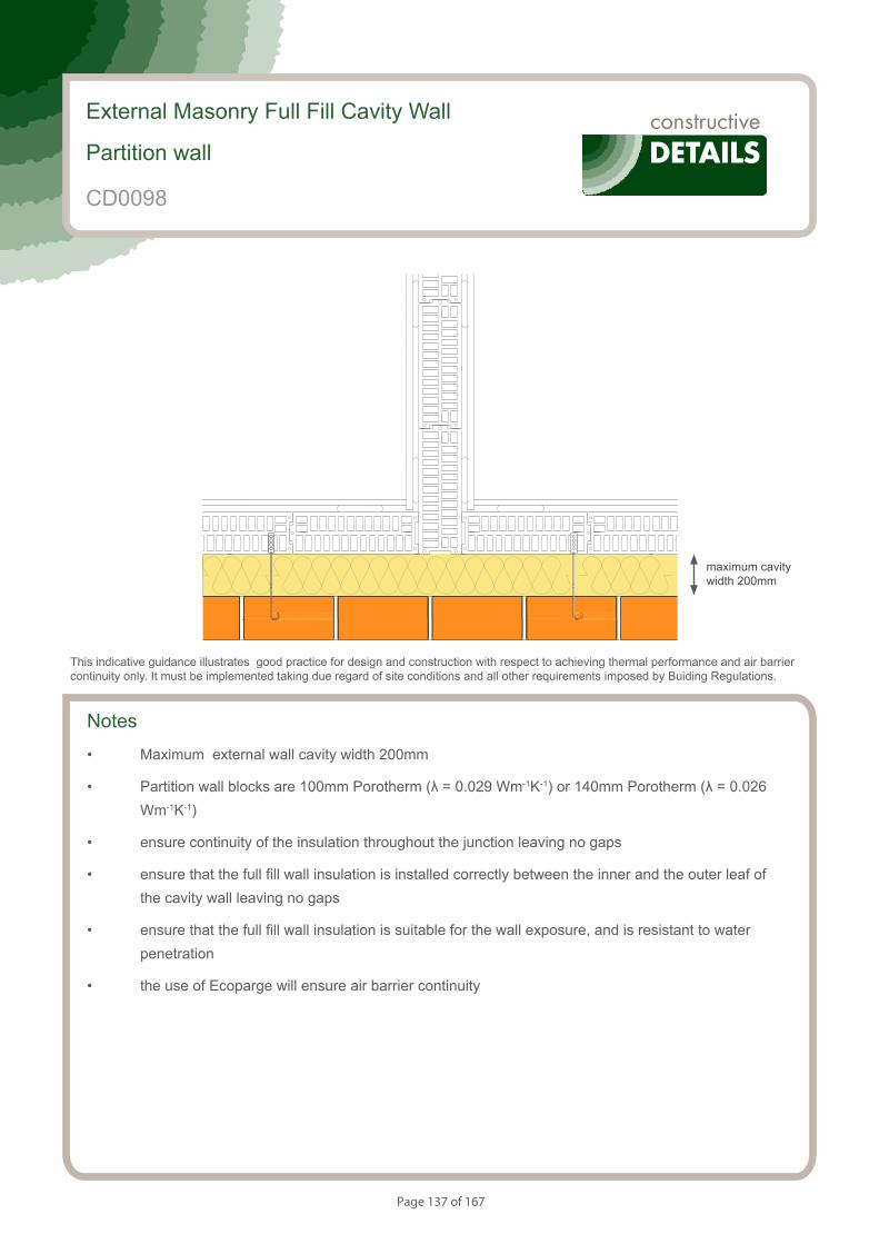
Page 137 of 167
S153084_CD40-1
Partition wall within a dwelling
Notes
• Maximum external wall cavity width 200mm
• Partition wall blocks are 100mm Porotherm (λ = 0.029 Wm-1K-1) or 140mm Porotherm (λ = 0.026 Wm-1K-1)
• ensure continuity of the insulation throughout the junction leaving no gaps
• ensure that the full fill wall insulation is installed correctly between the inner and the outer leaf of the cavity wall leaving no gaps
• ensure that the full fill wall insulation is suitable for the wall exposure, and is resistant to water penetration
• the use of Ecoparge will ensure air barrier continuity
External Masonry Full Fill Cavity Wall
Partition wall
This indicative guidance illustrates good practice for design and construction with respect to achieving thermal performance and air barrier continuity only. It must be implemented taking due regard of site conditions and all other requirements imposed by Buiding Regulations.
maximum cavity width 200mm
CD0098
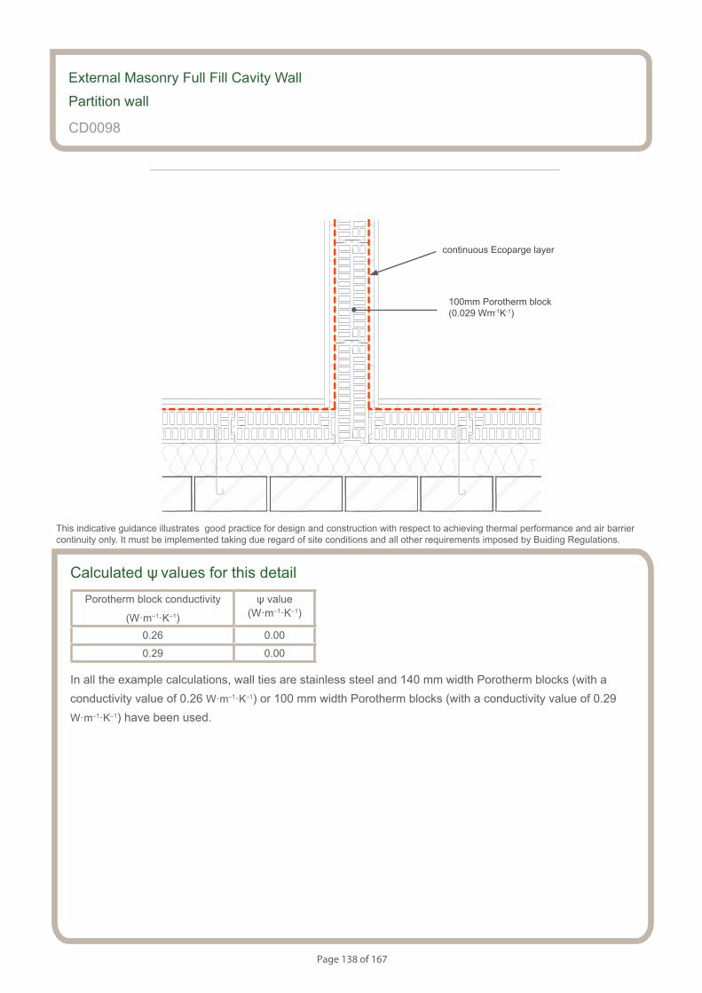
Page 138 of 167
Partition wall within a dwelling
S153084_CD40-2
Calculated ψ values for this detailPorotherm block conductivity
(W·m–1·K–1)
ψ value (W·m–1·K–1)
0.26 0.00
0.29 0.00
In all the example calculations, wall ties are stainless steel and 140 mm width Porotherm blocks (with a conductivity value of 0.26 W·m–1·K–1) or 100 mm width Porotherm blocks (with a conductivity value of 0.29 W·m–1·K–1) have been used.
External Masonry Full Fill Cavity Wall
Partition wall
CD0098
This indicative guidance illustrates good practice for design and construction with respect to achieving thermal performance and air barrier continuity only. It must be implemented taking due regard of site conditions and all other requirements imposed by Buiding Regulations.
continuous Ecoparge layer
100mm Porotherm block (0.029 Wm-1K-1)

Page 139 of 167
Notes (include details of any corrective action)
CD0098
Guidance Checklist
Date: ........................................... Site Manager/Supervisor: ......................................................................................
Site name: ........................................................................................... Plot No: ........................................................
Ref. Item Yes / No Inspected (initials & date)
1. Is the partition wall formed of 100 mm Porotherm blocks?
2. Is the wall full fill insulation installed correctly with no gaps?
3. Is the wall full fill insulation appropriate for moisture and wall exposure?
5. Is the continuity of the air barrier between the floor and the wall
achieved? If not, please provide details.
Copyright is owned by Constructive Details Limited. No copying or reproduction of the contents is permitted without the consent of Constructive Details Limited with the exception of the checklists. The checklists may be copied and used freely.
.......................................
.......................................
.......................................
.......................................
External Masonry Full Fill Cavity Wall
Partition wall
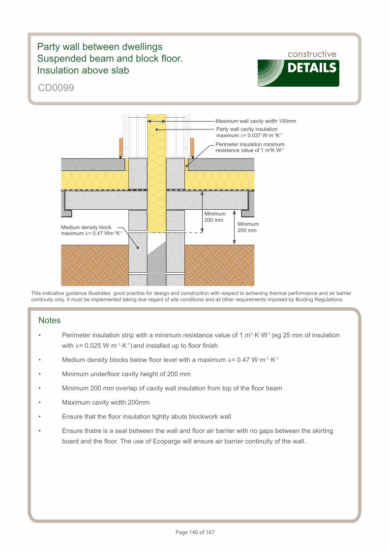
Page 140 of 167
S154083_CD41-1
Party wall. Suspended beam and block Floor. Insulation Above Slab.
Notes
• Perimeter insulation strip with a minimum resistance value of 1 m2·K·W-1 (eg 25 mm of insulation with l= 0.025 W·m-1·K-1) and installed up to floor finish
• Medium density blocks below floor level with a maximum l= 0.47 W·m-1·K-1
• Minimum underfloor cavity height of 200 mm
• Minimum 200 mm overlap of cavity wall insulation from top of the floor beam
• Maximum cavity width 200mm
• Ensure that the floor insulation tightly abuts blockwork wall
• Ensure thatre is a seal between the wall and floor air barrier with no gaps between the skirting board and the floor. The use of Ecoparge will ensure air barrier continuity of the wall.
Party wall between dwellingsSuspended beam and block floor. Insulation above slab
CD0099
This indicative guidance illustrates good practice for design and construction with respect to achieving thermal performance and air barrier continuity only. It must be implemented taking due regard of site conditions and all other requirements imposed by Buiding Regulations.
Maximum wall cavity width 100mm
Minimum 200 mm
Minimum 200 mmMedium density block
maximum l= 0.47 Wm-1K-1
Perimeter insulation minimum resistance value of 1 m2K·W-1
Party wall cavity insulation maximum l= 0.037 W·m-1K-1
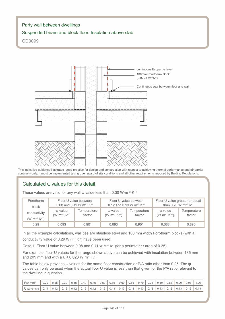
Page 141 of 167
S154083_CD41-2
Party wall. Suspended beam and block Floor. Insulation Above Slab.
Calculated ψ values for this detail
These values are valid for any wall U value less than 0.30 W·m–2·K–1
Porotherm
block
conductivity
(W·m–1·K–1)
Floor U value between 0.08 and 0.11 W·m–2·K–1
Floor U value between 0.12 and 0.19 W·m–2·K–1
Floor U value greater or equal than 0.20 W·m–2·K–1
ψ value (W·m–1·K–1)
Temperaturefactor
ψ value (W·m–1·K–1)
Temperaturefactor
ψ value (W·m–1·K–1)
Temperaturefactor
0.29 0.093 0.901 0.093 0.901 0.088 0.896
In all the example calculations, wall ties are stainless steel and 100 mm width Porotherm blocks (with a conductivity value of 0.29 W·m–1·K–1) have been used.
Case 1: Floor U value between 0.08 and 0.11 W·m–1·K–1 (for a perimteter / area of 0.25)
For example, floor U values for the range shown above can be achieved with insulation between 135 mm and 205 mm and with a l < 0.023 W·m–1·K–1.
The table below provides U values for the same floor construction or P/A ratio other than 0.25. The ψ values can only be used when the actual floor U value is less than that given for the P/A ratio relevant to the dwelling in question.
P/A mm-2 0.20 0.25 0.30 0.35 0.40 0.45 0.50 0.55 0.60 0.65 0.70 0.75 0.80 0.85 0.90 0.95 1.00
U (W·m–1·K–1) 0.11 0.12 0.12 0.12 0.12 0.12 0.13 0.13 0.13 0.13 0.13 0.13 0.13 0.13 0.13 0.13 0.13
Party wall between dwellings
Suspended beam and block floor. Insulation above slab
CD0099
This indicative guidance illustrates good practice for design and construction with respect to achieving thermal performance and air barrier continuity only. It must be implemented taking due regard of site conditions and all other requirements imposed by Buiding Regulations.
continuous Ecoparge layer
Continuous seal between floor and wall
100mm Porotherm block (0.029 Wm-1K-1)
Page 142 of 167
Case 2: Floor U value between 0.12 and 0.19 W·m–1·K–1 (for a perimteter / area of 0.25)
For example, floor U values for the range shown above can be achieved with insulation between 60 mm and 120 mm and with a l < 0.023 W·m–1·K–1.
The table below provides U values for the same floor construction or P/A ratio other than 0.25. The ψ values can only be used when the actual floor U value is less than that given for the P/A ratio relevant to the dwelling in question.
P/A mm-2 0.20 0.25 0.30 0.35 0.40 0.45 0.50 0.55 0.60 0.65 0.70 0.75 0.80 0.85 0.90 0.95 1.00
U (W·m–1·K–1) 0.18 0.19 0.19 0.20 0.21 0.21 0.22 0.22 0.23 0.23 0.23 0.23 0.23 0.23 0.24 0.24 0.24
Case 3: Floor U value > 0.20 W·m–1·K–1 (for a perimteter / area of 0.25)
For example, floor U values for the range shown above can be achieved with 50 mm insulation with a l < 0.023 W·m–1·K–1.
The table below provides U values for the same floor construction or P/A ratio other than 0.25. The ψ values can only be used when the actual floor U value is greater than that given for the P/A ratio relevant to the dwelling in question.
P/A mm-2 0.20 0.25 0.30 0.35 0.40 0.45 0.50 0.55 0.60 0.65 0.70 0.75 0.80 0.85 0.90 0.95 1.00
U (W·m–1·K–1) 0.19 0.20 0.22 0.22 0.23 0.24 0.24 0.25 0.25 0.25 0.26 0.26 0.26 0.26 0.27 0.27 0.27
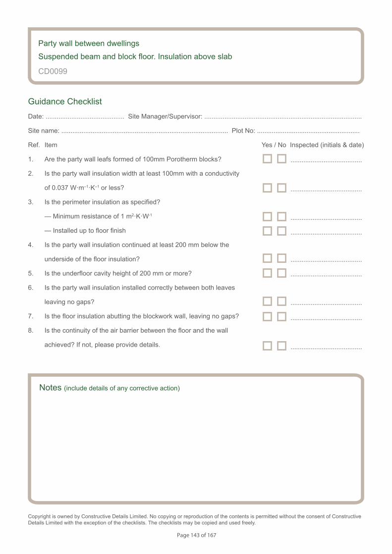
Page 143 of 167
Notes (include details of any corrective action)
CD0099
Guidance Checklist
Date: ........................................... Site Manager/Supervisor: ......................................................................................
Site name: ........................................................................................... Plot No: ........................................................
Ref. Item Yes / No Inspected (initials & date)
1. Are the party wall leafs formed of 100mm Porotherm blocks?
2. Is the party wall insulation width at least 100mm with a conductivity
of 0.037 W·m–1·K–1 or less?
3. Is the perimeter insulation as specified?
— Minimum resistance of 1 m2·K·W-1
— Installed up to floor finish
4. Is the party wall insulation continued at least 200 mm below the
underside of the floor insulation?
5. Is the underfloor cavity height of 200 mm or more?
6. Is the party wall insulation installed correctly between both leaves
leaving no gaps?
7. Is the floor insulation abutting the blockwork wall, leaving no gaps?
8. Is the continuity of the air barrier between the floor and the wall
achieved? If not, please provide details.
Copyright is owned by Constructive Details Limited. No copying or reproduction of the contents is permitted without the consent of Constructive Details Limited with the exception of the checklists. The checklists may be copied and used freely.
.......................................
.......................................
.......................................
.......................................
.......................................
.......................................
.......................................
.......................................
Party wall between dwellings
Suspended beam and block floor. Insulation above slab
.......................................

Page 144 of 167
S154083_CD42-1
Party wall. Beam and Block Floor. Insulation Above Slab. Thermal Block.
Notes
• Perimeter insulation strip with a minimum resistance value of 1 m2·K·W-1 (eg 25 mm of insulation with l = 0.025 W·m-1·K-1) and installed up to floor finish
• Thermal block of a minimum height of 65 mm and a maximum l = 0.078 W·m-1·K-1
• Medium density blocks below floor level with a maximum l = 0.47 W·m-1·K-1
• Minimum underfloor cavity height of 200 mm
• Minimum 200 mm overlap of cavity wall insulation from top of the floor beam
• Maximum cavity width 200mm
• Ensure that the floor insulation tightly abuts blockwork wall
• Ensure thatre is a seal between the wall and floor air barrier with no gaps between the skirting board and the floor. The use of Ecoparge will ensure air barrier continuity of the wall.
Party wall between dwellingsSuspended beam and block floor. Insulation above slab. Thermal block
CD0100
This indicative guidance illustrates good practice for design and construction with respect to achieving thermal performance and air barrier continuity only. It must be implemented taking due regard of site conditions and all other requirements imposed by Buiding Regulations.
Maximum wall cavity width 100mm
Minimum 200 mm
Minimum 200 mmMedium density block
maximum l= 0.47 Wm-1K-1
Perimeter insulation minimum resistance value of 1 m2K·W-1
Party wall cavity insulation maximum l= 0.037 W·m-1K-1
65 mm thermal block maximum l= 0.078 W·m-1·K-1
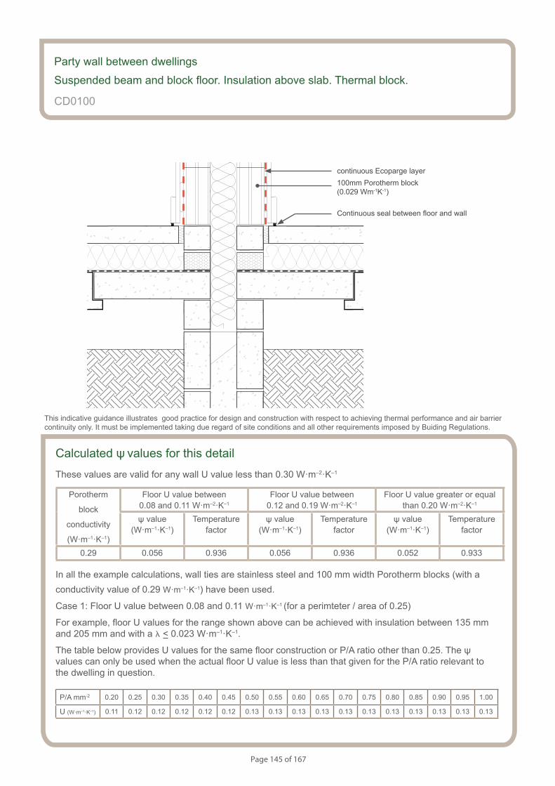
Page 145 of 167
S154083_CD42-2
Party wall. Beam and Block Floor. Insulation Above Slab. Thermal Block.
Calculated ψ values for this detail
These values are valid for any wall U value less than 0.30 W·m–2·K–1
Porotherm
block
conductivity
(W·m–1·K–1)
Floor U value between 0.08 and 0.11 W·m–2·K–1
Floor U value between 0.12 and 0.19 W·m–2·K–1
Floor U value greater or equal than 0.20 W·m–2·K–1
ψ value (W·m–1·K–1)
Temperaturefactor
ψ value (W·m–1·K–1)
Temperaturefactor
ψ value (W·m–1·K–1)
Temperaturefactor
0.29 0.056 0.936 0.056 0.936 0.052 0.933
In all the example calculations, wall ties are stainless steel and 100 mm width Porotherm blocks (with a conductivity value of 0.29 W·m–1·K–1) have been used.
Case 1: Floor U value between 0.08 and 0.11 W·m–1·K–1 (for a perimteter / area of 0.25)
For example, floor U values for the range shown above can be achieved with insulation between 135 mm and 205 mm and with a l < 0.023 W·m–1·K–1.
The table below provides U values for the same floor construction or P/A ratio other than 0.25. The ψ values can only be used when the actual floor U value is less than that given for the P/A ratio relevant to the dwelling in question.
P/A mm-2 0.20 0.25 0.30 0.35 0.40 0.45 0.50 0.55 0.60 0.65 0.70 0.75 0.80 0.85 0.90 0.95 1.00
U (W·m–1·K–1) 0.11 0.12 0.12 0.12 0.12 0.12 0.13 0.13 0.13 0.13 0.13 0.13 0.13 0.13 0.13 0.13 0.13
Party wall between dwellings
Suspended beam and block floor. Insulation above slab. Thermal block.
CD0100
This indicative guidance illustrates good practice for design and construction with respect to achieving thermal performance and air barrier continuity only. It must be implemented taking due regard of site conditions and all other requirements imposed by Buiding Regulations.
continuous Ecoparge layer
Continuous seal between floor and wall
100mm Porotherm block (0.029 Wm-1K-1)
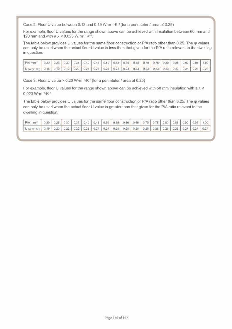
Page 146 of 167
Case 2: Floor U value between 0.12 and 0.19 W·m–1·K–1 (for a perimteter / area of 0.25)
For example, floor U values for the range shown above can be achieved with insulation between 60 mm and 120 mm and with a l < 0.023 W·m–1·K–1.
The table below provides U values for the same floor construction or P/A ratio other than 0.25. The ψ values can only be used when the actual floor U value is less than that given for the P/A ratio relevant to the dwelling in question.
P/A mm-2 0.20 0.25 0.30 0.35 0.40 0.45 0.50 0.55 0.60 0.65 0.70 0.75 0.80 0.85 0.90 0.95 1.00
U (W·m–1·K–1) 0.18 0.19 0.19 0.20 0.21 0.21 0.22 0.22 0.23 0.23 0.23 0.23 0.23 0.23 0.24 0.24 0.24
Case 3: Floor U value > 0.20 W·m–1·K–1 (for a perimteter / area of 0.25)
For example, floor U values for the range shown above can be achieved with 50 mm insulation with a l < 0.023 W·m–1·K–1.
The table below provides U values for the same floor construction or P/A ratio other than 0.25. The ψ values can only be used when the actual floor U value is greater than that given for the P/A ratio relevant to the dwelling in question.
P/A mm-2 0.20 0.25 0.30 0.35 0.40 0.45 0.50 0.55 0.60 0.65 0.70 0.75 0.80 0.85 0.90 0.95 1.00
U (W·m–1·K–1) 0.19 0.20 0.22 0.22 0.23 0.24 0.24 0.25 0.25 0.25 0.26 0.26 0.26 0.26 0.27 0.27 0.27
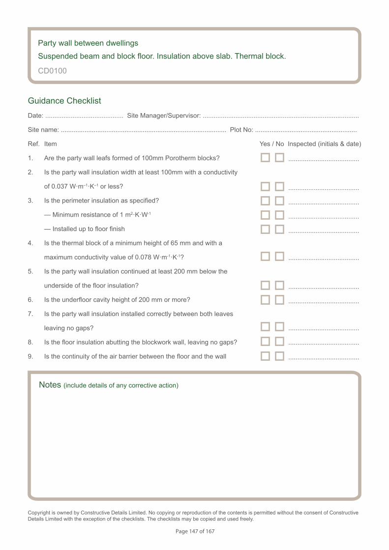
Page 147 of 167
Notes (include details of any corrective action)
CD0100
Guidance Checklist
Date: ........................................... Site Manager/Supervisor: ......................................................................................
Site name: ........................................................................................... Plot No: ........................................................
Ref. Item Yes / No Inspected (initials & date)
1. Are the party wall leafs formed of 100mm Porotherm blocks?
2. Is the party wall insulation width at least 100mm with a conductivity
of 0.037 W·m–1·K–1 or less?
3. Is the perimeter insulation as specified?
— Minimum resistance of 1 m2·K·W-1
— Installed up to floor finish
4. Is the thermal block of a minimum height of 65 mm and with a
maximum conductivity value of 0.078 W·m-1·K-1?
5. Is the party wall insulation continued at least 200 mm below the
underside of the floor insulation?
6. Is the underfloor cavity height of 200 mm or more?
7. Is the party wall insulation installed correctly between both leaves
leaving no gaps?
8. Is the floor insulation abutting the blockwork wall, leaving no gaps?
9. Is the continuity of the air barrier between the floor and the wall
Copyright is owned by Constructive Details Limited. No copying or reproduction of the contents is permitted without the consent of Constructive Details Limited with the exception of the checklists. The checklists may be copied and used freely.
.......................................
.......................................
.......................................
.......................................
.......................................
.......................................
.......................................
.......................................
.......................................
Party wall between dwellings
Suspended beam and block floor. Insulation above slab. Thermal block.
.......................................
.......................................
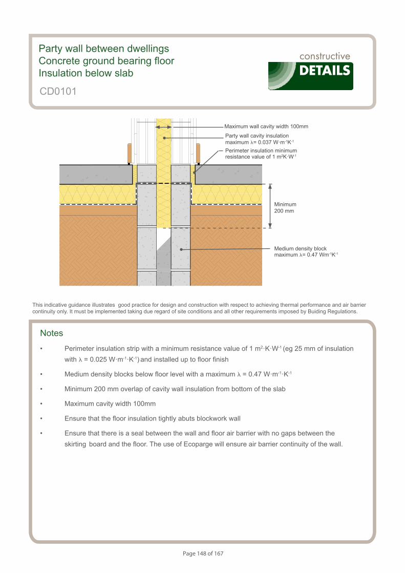
Page 148 of 167
S154083_CD43-1
Party wall. Ground Bearing Floor. Insulation Below Slab.
Notes
• Perimeter insulation strip with a minimum resistance value of 1 m2·K·W-1 (eg 25 mm of insulation with l = 0.025 W·m-1·K-1) and installed up to floor finish
• Medium density blocks below floor level with a maximum l = 0.47 W·m-1·K-1
• Minimum 200 mm overlap of cavity wall insulation from bottom of the slab
• Maximum cavity width 100mm
• Ensure that the floor insulation tightly abuts blockwork wall
• Ensure that there is a seal between the wall and floor air barrier with no gaps between the skirting board and the floor. The use of Ecoparge will ensure air barrier continuity of the wall.
Party wall between dwellingsConcrete ground bearing floor Insulation below slab
CD0101
This indicative guidance illustrates good practice for design and construction with respect to achieving thermal performance and air barrier continuity only. It must be implemented taking due regard of site conditions and all other requirements imposed by Buiding Regulations.
Maximum wall cavity width 100mm
Minimum 200 mm
Medium density block maximum l= 0.47 Wm-1K-1
Perimeter insulation minimum resistance value of 1 m2K·W-1
Party wall cavity insulation maximum l= 0.037 W·m-1K-1
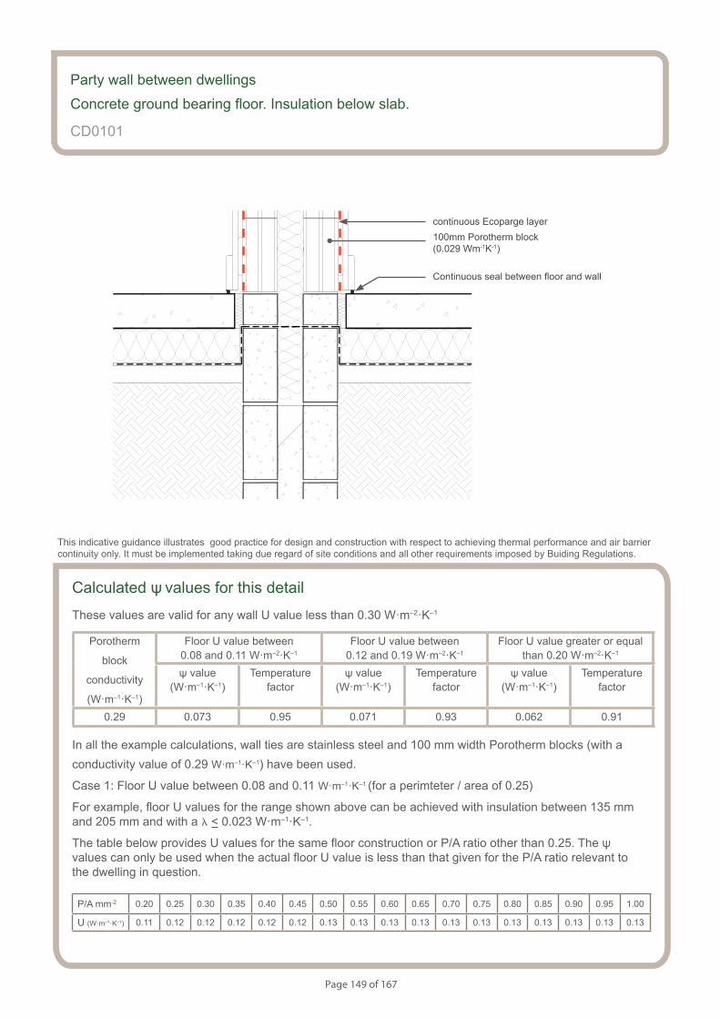
Page 149 of 167
Party wall. Ground Bearing Floor. Insulation Below Slab.
S154083_CD43-2
Calculated ψ values for this detail
These values are valid for any wall U value less than 0.30 W·m–2·K–1
Porotherm
block
conductivity
(W·m–1·K–1)
Floor U value between 0.08 and 0.11 W·m–2·K–1
Floor U value between 0.12 and 0.19 W·m–2·K–1
Floor U value greater or equal than 0.20 W·m–2·K–1
ψ value (W·m–1·K–1)
Temperaturefactor
ψ value (W·m–1·K–1)
Temperaturefactor
ψ value (W·m–1·K–1)
Temperaturefactor
0.29 0.073 0.95 0.071 0.93 0.062 0.91
In all the example calculations, wall ties are stainless steel and 100 mm width Porotherm blocks (with a conductivity value of 0.29 W·m–1·K–1) have been used.
Case 1: Floor U value between 0.08 and 0.11 W·m–1·K–1 (for a perimteter / area of 0.25)
For example, floor U values for the range shown above can be achieved with insulation between 135 mm and 205 mm and with a l < 0.023 W·m–1·K–1.
The table below provides U values for the same floor construction or P/A ratio other than 0.25. The ψ values can only be used when the actual floor U value is less than that given for the P/A ratio relevant to the dwelling in question.
P/A mm-2 0.20 0.25 0.30 0.35 0.40 0.45 0.50 0.55 0.60 0.65 0.70 0.75 0.80 0.85 0.90 0.95 1.00
U (W·m–1·K–1) 0.11 0.12 0.12 0.12 0.12 0.12 0.13 0.13 0.13 0.13 0.13 0.13 0.13 0.13 0.13 0.13 0.13
Party wall between dwellings
Concrete ground bearing floor. Insulation below slab.
CD0101
This indicative guidance illustrates good practice for design and construction with respect to achieving thermal performance and air barrier continuity only. It must be implemented taking due regard of site conditions and all other requirements imposed by Buiding Regulations.
continuous Ecoparge layer
Continuous seal between floor and wall
100mm Porotherm block (0.029 Wm-1K-1)
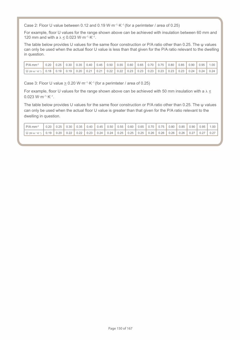
Page 150 of 167
Case 2: Floor U value between 0.12 and 0.19 W·m–1·K–1 (for a perimteter / area of 0.25)
For example, floor U values for the range shown above can be achieved with insulation between 60 mm and 120 mm and with a l < 0.023 W·m–1·K–1.
The table below provides U values for the same floor construction or P/A ratio other than 0.25. The ψ values can only be used when the actual floor U value is less than that given for the P/A ratio relevant to the dwelling in question.
P/A mm-2 0.20 0.25 0.30 0.35 0.40 0.45 0.50 0.55 0.60 0.65 0.70 0.75 0.80 0.85 0.90 0.95 1.00
U (W·m–1·K–1) 0.18 0.19 0.19 0.20 0.21 0.21 0.22 0.22 0.23 0.23 0.23 0.23 0.23 0.23 0.24 0.24 0.24
Case 3: Floor U value > 0.20 W·m–1·K–1 (for a perimteter / area of 0.25)
For example, floor U values for the range shown above can be achieved with 50 mm insulation with a l < 0.023 W·m–1·K–1.
The table below provides U values for the same floor construction or P/A ratio other than 0.25. The ψ values can only be used when the actual floor U value is greater than that given for the P/A ratio relevant to the dwelling in question.
P/A mm-2 0.20 0.25 0.30 0.35 0.40 0.45 0.50 0.55 0.60 0.65 0.70 0.75 0.80 0.85 0.90 0.95 1.00
U (W·m–1·K–1) 0.19 0.20 0.22 0.22 0.23 0.24 0.24 0.25 0.25 0.25 0.26 0.26 0.26 0.26 0.27 0.27 0.27

Page 151 of 167
Notes (include details of any corrective action)
CD0101
Guidance Checklist
Date: ........................................... Site Manager/Supervisor: ......................................................................................
Site name: ........................................................................................... Plot No: ........................................................
Ref. Item Yes / No Inspected (initials & date)
1. Are the party wall leafs formed of 100mm Porotherm blocks?
2. Is the party wall insulation width at least 100mm with a conductivity
of 0.037 W·m–1·K–1 or less?
3. Is the perimeter insulation as specified?
— Minimum resistance of 1 m2·K·W-1
— Installed up to floor finish
4. Is the party wall insulation continued at least 200 mm below the
top of the floor insulation?
5. Is the party wall insulation installed correctly between both leaves
leaving no gaps?
6. Is the floor insulation abutting the blockwork wall, leaving no gaps?
7. Is the continuity of the air barrier between the floor and the wall
achieved? If not, please provide details.
Copyright is owned by Constructive Details Limited. No copying or reproduction of the contents is permitted without the consent of Constructive Details Limited with the exception of the checklists. The checklists may be copied and used freely.
.......................................
.......................................
.......................................
.......................................
.......................................
.......................................
.......................................
Party wall between dwellings
Concrete ground bearing floor. Insulation below slab.
.......................................
.......................................
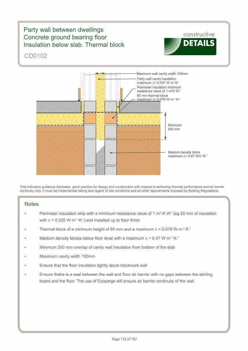
Page 152 of 167
S154083_CD44-1
Party wall. Ground Bearing Floor. Insulation Below Slab. Thermal block
Notes
• Perimeter insulation strip with a minimum resistance value of 1 m2·K·W-1 (eg 25 mm of insulation with l = 0.025 W·m-1·K-1) and installed up to floor finish
• Thermal block of a minimum height of 65 mm and a maximum l = 0.078 W·m-1·K-1
• Medium density blocks below floor level with a maximum l = 0.47 W·m-1·K-1
• Minimum 200 mm overlap of cavity wall insulation from bottom of the slab
• Maximum cavity width 100mm
• Ensure that the floor insulation tightly abuts blockwork wall
• Ensure thatre is a seal between the wall and floor air barrier with no gaps between the skirting board and the floor. The use of Ecoparge will ensure air barrier continuity of the wall.
Party wall between dwellingsConcrete ground bearing floorInsulation below slab. Thermal block
CD0102
This indicative guidance illustrates good practice for design and construction with respect to achieving thermal performance and air barrier continuity only. It must be implemented taking due regard of site conditions and all other requirements imposed by Buiding Regulations.
Minimum 200 mm
Medium density block maximum l= 0.47 Wm-1K-1
Maximum wall cavity width 100mm
Perimeter insulation minimum resistance value of 1 m2K·W-1
Party wall cavity insulation maximum l= 0.037 W·m-1K-1
65 mm thermal block maximum l= 0.078 W·m-1·K-1
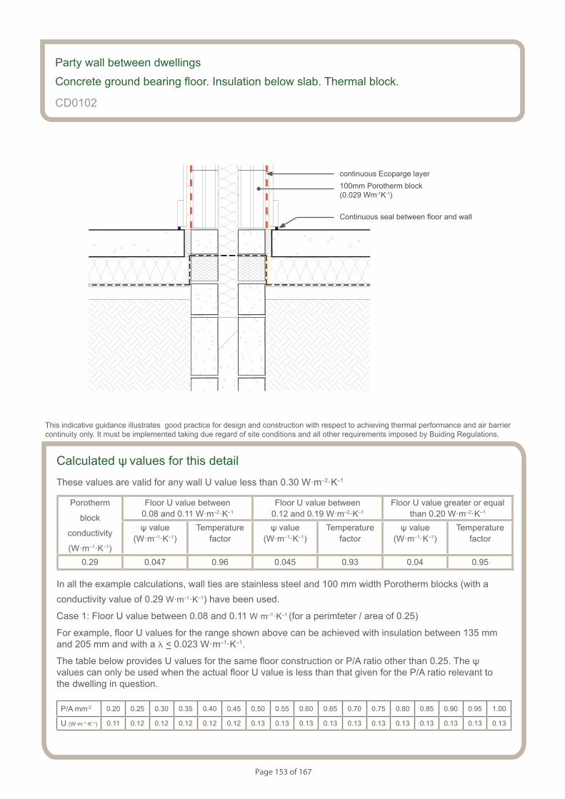
Page 153 of 167
S154083_CD44-2
Party wall. Ground Bearing Floor. Insulation Below Slab. Thermal block
Calculated ψ values for this detail
These values are valid for any wall U value less than 0.30 W·m–2·K–1
Porotherm
block
conductivity
(W·m–1·K–1)
Floor U value between 0.08 and 0.11 W·m–2·K–1
Floor U value between 0.12 and 0.19 W·m–2·K–1
Floor U value greater or equal than 0.20 W·m–2·K–1
ψ value (W·m–1·K–1)
Temperaturefactor
ψ value (W·m–1·K–1)
Temperaturefactor
ψ value (W·m–1·K–1)
Temperaturefactor
0.29 0.047 0.96 0.045 0.93 0.04 0.95
In all the example calculations, wall ties are stainless steel and 100 mm width Porotherm blocks (with a conductivity value of 0.29 W·m–1·K–1) have been used.
Case 1: Floor U value between 0.08 and 0.11 W·m–1·K–1 (for a perimteter / area of 0.25)
For example, floor U values for the range shown above can be achieved with insulation between 135 mm and 205 mm and with a l < 0.023 W·m–1·K–1.
The table below provides U values for the same floor construction or P/A ratio other than 0.25. The ψ values can only be used when the actual floor U value is less than that given for the P/A ratio relevant to the dwelling in question.
P/A mm-2 0.20 0.25 0.30 0.35 0.40 0.45 0.50 0.55 0.60 0.65 0.70 0.75 0.80 0.85 0.90 0.95 1.00
U (W·m–1·K–1) 0.11 0.12 0.12 0.12 0.12 0.12 0.13 0.13 0.13 0.13 0.13 0.13 0.13 0.13 0.13 0.13 0.13
Party wall between dwellings
Concrete ground bearing floor. Insulation below slab. Thermal block.
CD0102
This indicative guidance illustrates good practice for design and construction with respect to achieving thermal performance and air barrier continuity only. It must be implemented taking due regard of site conditions and all other requirements imposed by Buiding Regulations.
continuous Ecoparge layer
Continuous seal between floor and wall
100mm Porotherm block (0.029 Wm-1K-1)
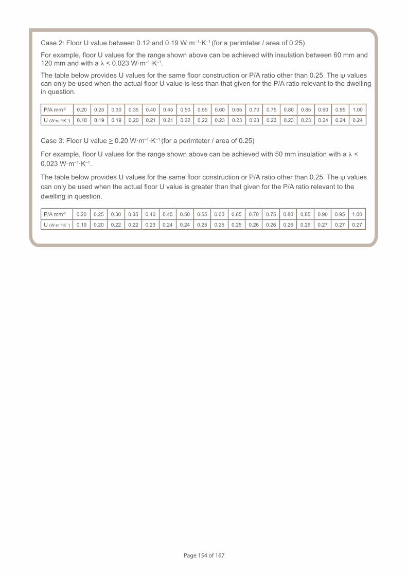
Page 154 of 167
Case 2: Floor U value between 0.12 and 0.19 W·m–1·K–1 (for a perimteter / area of 0.25)
For example, floor U values for the range shown above can be achieved with insulation between 60 mm and 120 mm and with a l < 0.023 W·m–1·K–1.
The table below provides U values for the same floor construction or P/A ratio other than 0.25. The ψ values can only be used when the actual floor U value is less than that given for the P/A ratio relevant to the dwelling in question.
P/A mm-2 0.20 0.25 0.30 0.35 0.40 0.45 0.50 0.55 0.60 0.65 0.70 0.75 0.80 0.85 0.90 0.95 1.00
U (W·m–1·K–1) 0.18 0.19 0.19 0.20 0.21 0.21 0.22 0.22 0.23 0.23 0.23 0.23 0.23 0.23 0.24 0.24 0.24
Case 3: Floor U value > 0.20 W·m–1·K–1 (for a perimteter / area of 0.25)
For example, floor U values for the range shown above can be achieved with 50 mm insulation with a l < 0.023 W·m–1·K–1.
The table below provides U values for the same floor construction or P/A ratio other than 0.25. The ψ values can only be used when the actual floor U value is greater than that given for the P/A ratio relevant to the dwelling in question.
P/A mm-2 0.20 0.25 0.30 0.35 0.40 0.45 0.50 0.55 0.60 0.65 0.70 0.75 0.80 0.85 0.90 0.95 1.00
U (W·m–1·K–1) 0.19 0.20 0.22 0.22 0.23 0.24 0.24 0.25 0.25 0.25 0.26 0.26 0.26 0.26 0.27 0.27 0.27
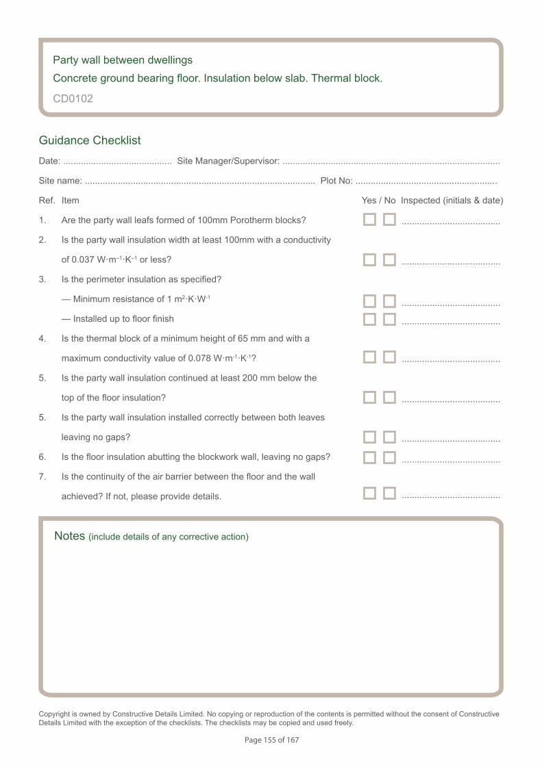
Page 155 of 167
Notes (include details of any corrective action)
CD0102
Guidance Checklist
Date: ........................................... Site Manager/Supervisor: ......................................................................................
Site name: ........................................................................................... Plot No: ........................................................
Ref. Item Yes / No Inspected (initials & date)
1. Are the party wall leafs formed of 100mm Porotherm blocks?
2. Is the party wall insulation width at least 100mm with a conductivity
of 0.037 W·m–1·K–1 or less?
3. Is the perimeter insulation as specified?
— Minimum resistance of 1 m2·K·W-1
— Installed up to floor finish
4. Is the thermal block of a minimum height of 65 mm and with a
maximum conductivity value of 0.078 W·m-1·K-1?
5. Is the party wall insulation continued at least 200 mm below the
top of the floor insulation?
5. Is the party wall insulation installed correctly between both leaves
leaving no gaps?
6. Is the floor insulation abutting the blockwork wall, leaving no gaps?
7. Is the continuity of the air barrier between the floor and the wall
achieved? If not, please provide details.
Copyright is owned by Constructive Details Limited. No copying or reproduction of the contents is permitted without the consent of Constructive Details Limited with the exception of the checklists. The checklists may be copied and used freely.
.......................................
.......................................
.......................................
.......................................
.......................................
.......................................
.......................................
.......................................
Party wall between dwellings
Concrete ground bearing floor. Insulation below slab. Thermal block.
.......................................
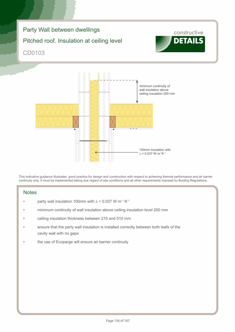
Page 156 of 167
S154083_CD45-1
Party Wall. Ventilated loft (Insulation at ceiling level)
Notes
• party wall insulation 100mm with l = 0.037 W·m-1·K-1
• minimum continuity of wall insulation above ceiling insulation level 200 mm
• ceiling insulation thickness between 210 and 510 mm
• ensure that the party wall insulation is installed correctly between both leafs of the cavity wall with no gaps
• the use of Ecoparge will ensure air barrier continuity
Party Wall between dwellings
Pitched roof. Insulation at ceiling level
CD0103
This indicative guidance illustrates good practice for design and construction with respect to achieving thermal performance and air barrier continuity only. It must be implemented taking due regard of site conditions and all other requirements imposed by Buiding Regulations.
minimum continuity of wall insulation above ceiling insulation 200 mm
100mm insulation with l = 0.037 W·m-1K-1
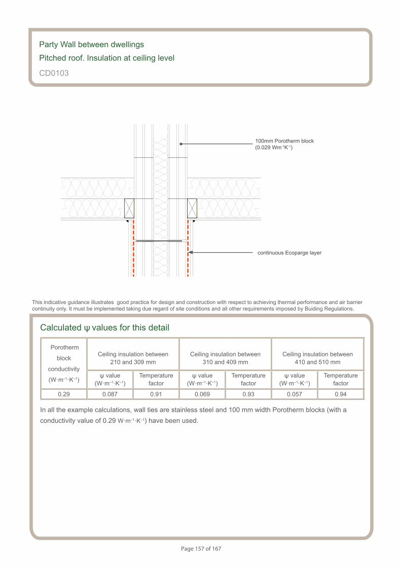
Page 157 of 167
S154083_CD45-2
Party Wall. Ventilated loft (Insulation at ceiling level)
Calculated ψ values for this detail
Porotherm
block
conductivity
(W·m–1·K–1)
Ceiling insulation between 210 and 309 mm
Ceiling insulation between 310 and 409 mm
Ceiling insulation between410 and 510 mm
ψ value (W·m–1·K–1)
Temperaturefactor
ψ value (W·m–1·K–1)
Temperaturefactor
ψ value (W·m–1·K–1)
Temperaturefactor
0.29 0.087 0.91 0.069 0.93 0.057 0.94
In all the example calculations, wall ties are stainless steel and 100 mm width Porotherm blocks (with a conductivity value of 0.29 W·m–1·K–1) have been used.
Party Wall between dwellings
Pitched roof. Insulation at ceiling level
CD0103
This indicative guidance illustrates good practice for design and construction with respect to achieving thermal performance and air barrier continuity only. It must be implemented taking due regard of site conditions and all other requirements imposed by Buiding Regulations.
continuous Ecoparge layer
100mm Porotherm block (0.029 Wm-1K-1)

Page 158 of 167
Notes (include details of any corrective action)
CD0103
Guidance Checklist
Date: ........................................... Site Manager/Supervisor: ......................................................................................
Site name: ........................................................................................... Plot No: ........................................................
Ref. Item Yes / No Inspected (initials & date)
1. Are the party wall leafs formed of 100mm Porotherm blocks?
2. Is the party wall insulation width at least 100mm with a conductivity
of 0.037 W·m–1·K–1 or less?
3. Is the ceiling insulation thickness between 210 and 510mm thickness?
4. Is the party wall insulation continued above the ceiling insulation level
at least 200 mm?
5. Is the party wall insulation installed correctly between both leaves
leaving no gaps?
6. Is the continuity of the air barrier achieved? If not, please provide
details.
Copyright is owned by Constructive Details Limited. No copying or reproduction of the contents is permitted without the consent of Constructive Details Limited with the exception of the checklists. The checklists may be copied and used freely.
.......................................
.......................................
.......................................
.......................................
.......................................
.......................................
Party Wall between dwellings
Pitched roof. Insulation at ceiling level
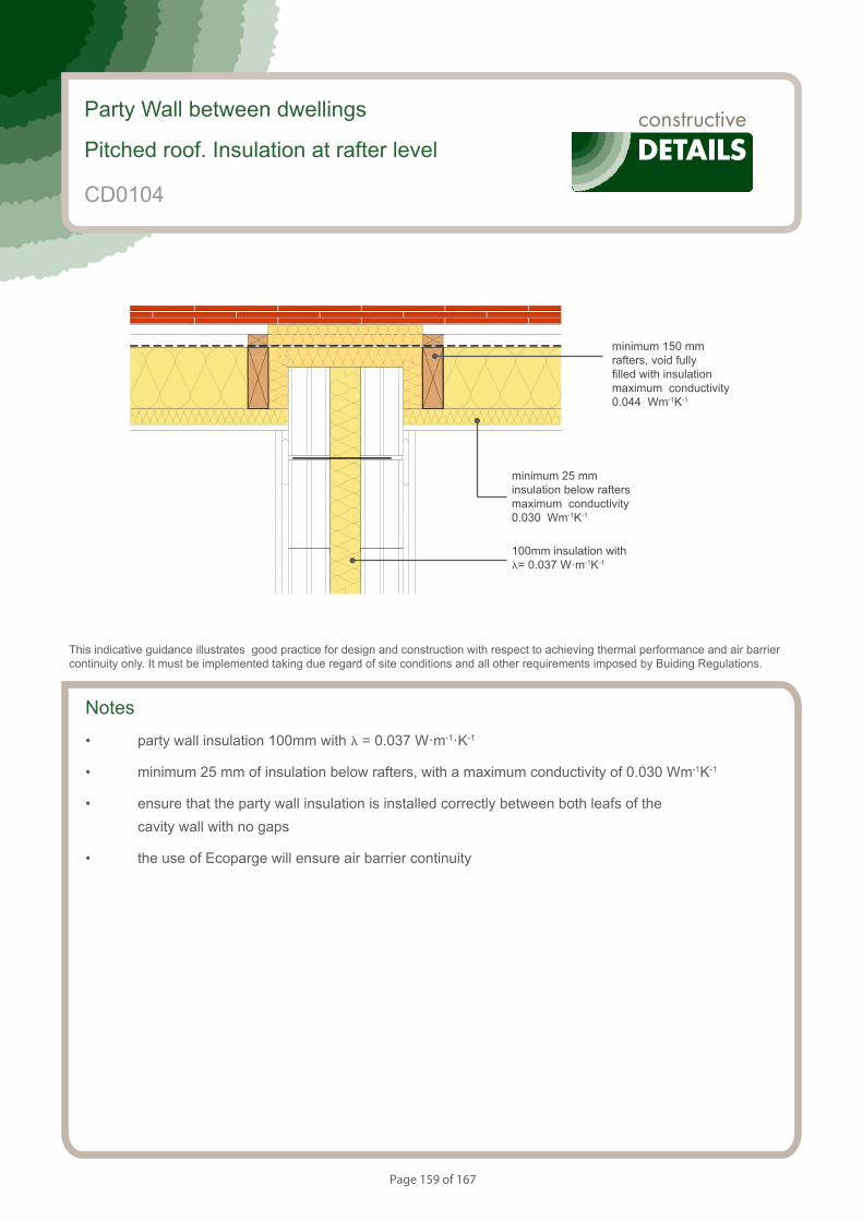
Page 159 of 167
S154083_CD46-1
Party Wall. Unventilated loft (Insulation at ceiling level)
Notes
• party wall insulation 100mm with l = 0.037 W·m-1·K-1
• minimum 25 mm of insulation below rafters, with a maximum conductivity of 0.030 Wm-1K-1
• ensure that the party wall insulation is installed correctly between both leafs of the cavity wall with no gaps
• the use of Ecoparge will ensure air barrier continuity
Party Wall between dwellings
Pitched roof. Insulation at rafter level
CD0104
This indicative guidance illustrates good practice for design and construction with respect to achieving thermal performance and air barrier continuity only. It must be implemented taking due regard of site conditions and all other requirements imposed by Buiding Regulations.
100mm insulation with l= 0.037 W·m-1K-1
minimum 25 mm insulation below rafters maximum conductivity 0.030 Wm-1K-1
minimum 150 mm rafters, void fully filled with insulation maximum conductivity 0.044 Wm-1K-1
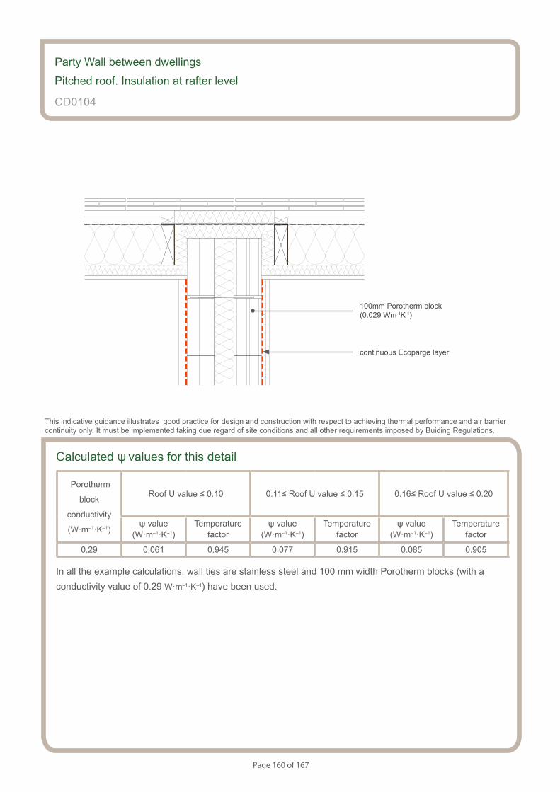
Page 160 of 167
S154083_CD46-2
Party Wall. Unventilated loft (Insulation at ceiling level)
Calculated ψ values for this detail
Porotherm
block
conductivity
(W·m–1·K–1)
Roof U value ≤ 0.10 0.11≤ Roof U value ≤ 0.15 0.16≤ Roof U value ≤ 0.20
ψ value (W·m–1·K–1)
Temperaturefactor
ψ value (W·m–1·K–1)
Temperaturefactor
ψ value (W·m–1·K–1)
Temperaturefactor
0.29 0.061 0.945 0.077 0.915 0.085 0.905
In all the example calculations, wall ties are stainless steel and 100 mm width Porotherm blocks (with a conductivity value of 0.29 W·m–1·K–1) have been used.
Party Wall between dwellings
Pitched roof. Insulation at rafter level
CD0104
This indicative guidance illustrates good practice for design and construction with respect to achieving thermal performance and air barrier continuity only. It must be implemented taking due regard of site conditions and all other requirements imposed by Buiding Regulations.
continuous Ecoparge layer
100mm Porotherm block (0.029 Wm-1K-1)
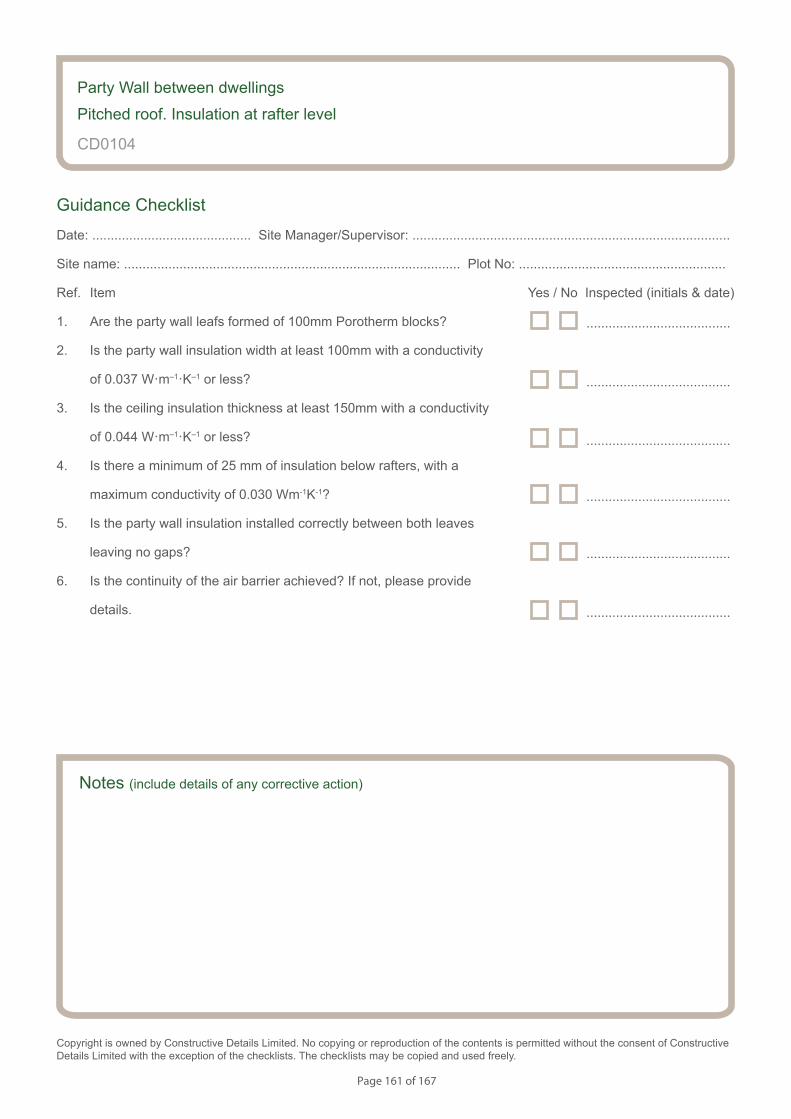
Page 161 of 167
Notes (include details of any corrective action)
CD0104
Guidance Checklist
Date: ........................................... Site Manager/Supervisor: ......................................................................................
Site name: ........................................................................................... Plot No: ........................................................
Ref. Item Yes / No Inspected (initials & date)
1. Are the party wall leafs formed of 100mm Porotherm blocks?
2. Is the party wall insulation width at least 100mm with a conductivity
of 0.037 W·m–1·K–1 or less?
3. Is the ceiling insulation thickness at least 150mm with a conductivity
of 0.044 W·m–1·K–1 or less?
4. Is there a minimum of 25 mm of insulation below rafters, with a
maximum conductivity of 0.030 Wm-1K-1?
5. Is the party wall insulation installed correctly between both leaves
leaving no gaps?
6. Is the continuity of the air barrier achieved? If not, please provide
details.
Copyright is owned by Constructive Details Limited. No copying or reproduction of the contents is permitted without the consent of Constructive Details Limited with the exception of the checklists. The checklists may be copied and used freely.
.......................................
.......................................
.......................................
.......................................
.......................................
.......................................
Party Wall between dwellings
Pitched roof. Insulation at rafter level
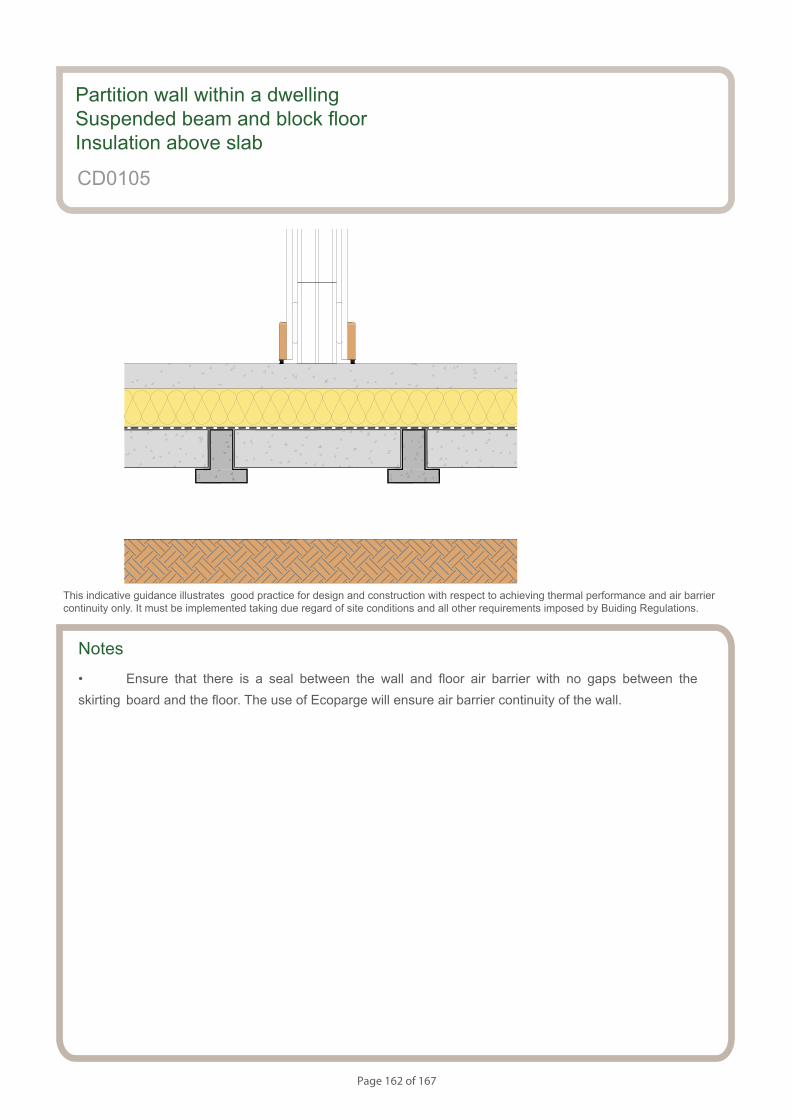
Page 162 of 167
S154083_CD47-1
Partition wall. Beam and Block Floor. Insulation Above Slab.
Notes
• Ensure that there is a seal between the wall and floor air barrier with no gaps between the skirting board and the floor. The use of Ecoparge will ensure air barrier continuity of the wall.
Partition wall within a dwellingSuspended beam and block floorInsulation above slab
CD0105
This indicative guidance illustrates good practice for design and construction with respect to achieving thermal performance and air barrier continuity only. It must be implemented taking due regard of site conditions and all other requirements imposed by Buiding Regulations.
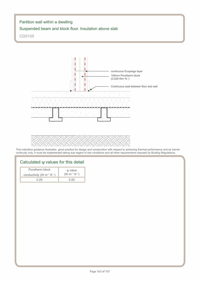
Page 163 of 167
S154083_CD47-2
Partition wall. Beam and Block Floor. Insulation Above Slab.
Partition wall within a dwelling
Suspended beam and block floor. Insulation above slab
CD0105
This indicative guidance illustrates good practice for design and construction with respect to achieving thermal performance and air barrier continuity only. It must be implemented taking due regard of site conditions and all other requirements imposed by Buiding Regulations.
continuous Ecoparge layer
Continuous seal between floor and wall
100mm Porotherm block (0.029 Wm-1K-1)
Calculated ψ values for this detailPorotherm block
conductivity (W·m–1·K–1)ψ value
(W·m–1·K–1)
0.29 0.00
Page 164 of 167
CD0105
Guidance Checklist
Date: ........................................... Site Manager/Supervisor: ......................................................................................
Site name: ........................................................................................... Plot No: ........................................................
Ref. Item Yes / No Inspected (initials & date)
1. Is the partition wall formed of 100mm Porotherm blocks?
2. Is the continuity of the air barrier achieved? If not, please provide
details.
Partition wall within a dwelling
Suspended beam and block floor. Insulation above slab
.......................................
.......................................
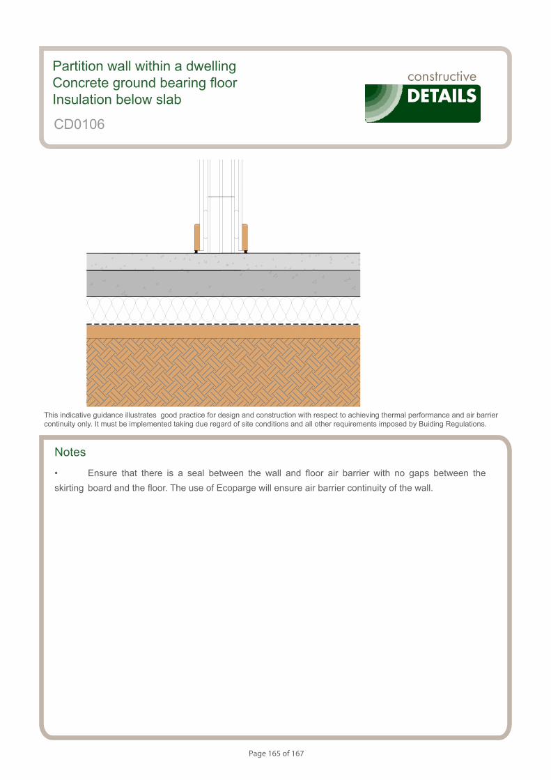
Page 165 of 167
S154083_CD49-1
Partition wall. Concrete Ground Bearing Floor. Insulation Below Slab.
Notes
• Ensure that there is a seal between the wall and floor air barrier with no gaps between the skirting board and the floor. The use of Ecoparge will ensure air barrier continuity of the wall.
Partition wall within a dwellingConcrete ground bearing floor Insulation below slab
CD0106
This indicative guidance illustrates good practice for design and construction with respect to achieving thermal performance and air barrier continuity only. It must be implemented taking due regard of site conditions and all other requirements imposed by Buiding Regulations.
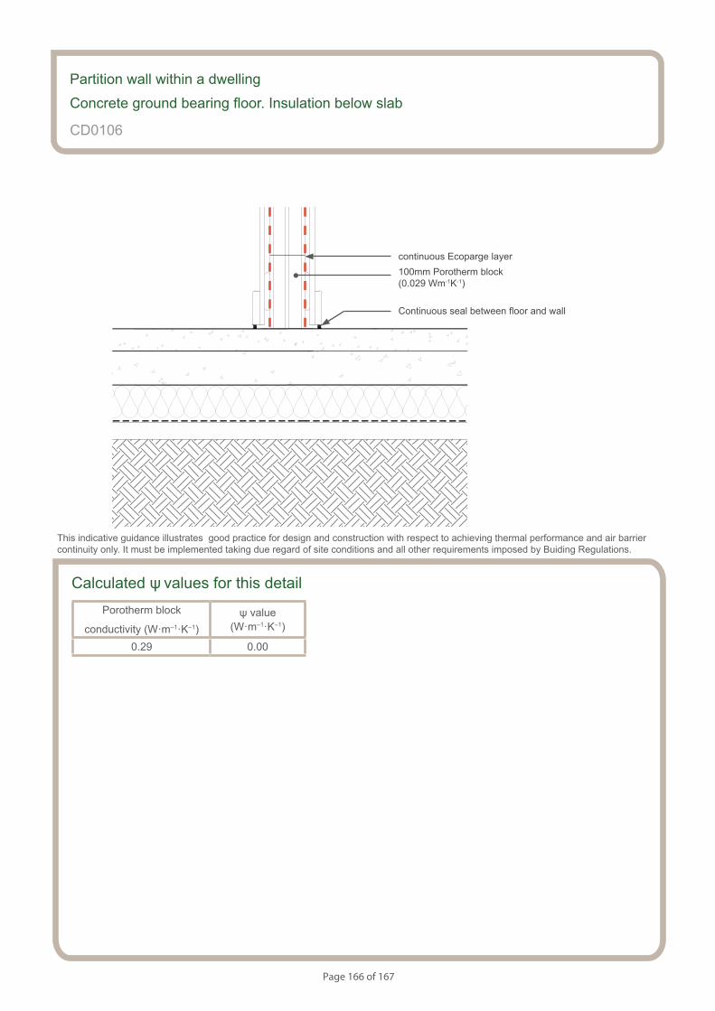
Page 166 of 167
S154083_CD49-2
Partition wall. Concrete Ground Bearing Floor. Insulation Below Slab.
Partition wall within a dwelling
Concrete ground bearing floor. Insulation below slab
CD0106
This indicative guidance illustrates good practice for design and construction with respect to achieving thermal performance and air barrier continuity only. It must be implemented taking due regard of site conditions and all other requirements imposed by Buiding Regulations.
continuous Ecoparge layer
Continuous seal between floor and wall
100mm Porotherm block (0.029 Wm-1K-1)
Calculated ψ values for this detailPorotherm block
conductivity (W·m–1·K–1)ψ value
(W·m–1·K–1)
0.29 0.00
Page 167 of 167
CD0106
Guidance Checklist
Date: ........................................... Site Manager/Supervisor: ......................................................................................
Site name: ........................................................................................... Plot No: ........................................................
Ref. Item Yes / No Inspected (initials & date)
1. Is the partition wall formed of 100mm Porotherm blocks?
2. Is the continuity of the air barrier achieved? If not, please provide
details.
Partition wall within a dwelling
Concrete ground bearing floor. Insulation below slab
.......................................
.......................................