Embed Size (px)
Citation preview
ABSTRACTdex of ~0.13, a flow zone indicator of ~0.73 and a net to grossratio of ~0.62. This reservoir is heterogeneous with clay-richlimestone/dolomite, having permeability in the range of 1 mill-idarcy (md) to 15 md and porosity ranging between 5% and20%. Production in the LF formation is expected to be morechallenging than in common reservoirs due to its low kh, ahigh hydrogen sulfide (H2S) content of ~7% and its crude oilquality.
The wells in this reservoir are drilled as horizontal multilat-eral wells and completed as open hole completions. Severalwells have been acidized using treatments based on adjacentfield recipes, but acidizing in these cases resulted in completeloss of production. To discover the cause, the LF oil was testedand found to have a tendency to precipitate asphaltene. Thecalculated colloidal instability index (CII) for the LF oil wasfound to be above 0.9, indicating that the LF oil is unstable,and as noted, tends to precipitate asphaltenes1. The LF forma-tion was drilled with oil-based mud (OBM), which created anOBM cake that acted as an impermeable barrier on the forma-tion face; the subsequent mud cake removal required acidtreatment. While hydrochloric (HCl) and organic acids havebeen extensively used in acid stimulation treatments and acidwashes to enhance well productivity or injectivity, one mainpotential problem associated with these acids is incompatibil-ity issues with the reservoir's oil — which appeared to be afactor with these wells. Acid-oil incompatibility causes precipi-tation of asphaltene particles, forming a thick sludge that canplug the formation, resulting in severe formation damage2-4.
Emulsion Formation and Asphaltene Precipitation
Asphaltenes are negatively charged particles, composed mainlyof condensed aromatic ring structures containing oxygen, sul-fur and nitrogen atoms. Asphaltenes exist in heavy crude oil asdispersed colloidal particles that are stabilized by adsorbedresin “maltene” particles. Both asphaltenes and resins formstabilized micelles in heavy crude oil2. When these stabilizedmicelles are disrupted by acid contact, the result is asphalteneprecipitation, triggered by two main mechanisms: dissolutionof resins and neutralization of asphaltenes. Following the dis-solution of resins and neutralization of asphaltenes by protonions, H+, the destabilized colloidal asphaltene particles form
The increasing demand for energy has extended the develop-ment horizon toward relatively tighter formations all over theworld. In Saudi Arabia, hydrochloric (HCl) and organic acidshave been used extensively to enhance well productivity or injectivity in low permeability formations. The use of theseacids, however, is associated with severe formation damage,which is attributed to acid-oil emulsion formation and/or as-phaltene precipitation in some of the low permeability carbon-ate reservoirs. Consequently, a detailed study of differentfactors that influence the mechanisms of acid-oil emulsion for-mation and asphaltene precipitation was carried out for thesereservoirs. Several compatibility studies were conducted usingrepresentative crude samples and different acid systems, suchas HCl and formic acid. The experiments were conducted atvarious temperatures up to 240 °F using high-pressure/hightemperature (HPHT) aging cells for both live and spent acidsamples; some of the experiments also included anti-sludge,iron control and demulsifier chemical additives. In addition,another set of experiments was performed in the presence offerric ions (Fe3+). The total iron concentration in these experi-ments varied between 0 ppm and 1,000 ppm.
The results obtained from this study revealed that the acidsystems were not compatible with several representative oilfield samples. The amount of asphaltene precipitation and thestability of the emulsions created increased significantly in thepresence of Fe3+. Several wells that had already been acidizedtherefore showed major damage.
This article discusses different tests conducted to identify,quantify and treat acid-oil emulsion formation and/or asphal-tene precipitation in tight carbonate reservoirs. It also providesdetails of a special solvent treatment fluid recommended to re-vive dead wells that were damaged by acid-induced emulsionformation and asphaltene precipitation.
INTRODUCTION
The Lower Fadhili (LF) formation is the deepest of the UpperJurassic limestone reservoirs in field F. Underlying two othercarbonate reservoirs, the LF formation has been appraised as arelatively lower quality formation, with a reservoir quality in-
Investigation of Acid-Induced EmulsionFormation and Asphaltene Precipitationin Low Permeability CarbonateReservoirs Authors: Tariq A. Al-Mubarak, Dr. Mohammed H. Al-Khaldi, Hussain A. Al-Ibrahim, Majid M. Rafie and Omar Al-Dajani
FALL 2015 SAUDI ARAMCO JOURNAL OF TECHNOLOGY
SAUDI ARAMCO JOURNAL OF TECHNOLOGY FALL 2015
DIF mud cake. Chemical means include acids, oxidizers,chelating agents, enzymes or a combination of these chemicals,which are used to dissolve the CaCO3 bridging materials in themud cake. Achieving uniform mud cake removal across longhorizontal sections with open hole completions using rapid reacting chemicals, such as HCl acid, is a challenging task8. Although the use of harsh chemicals, such as HCl acid, iswidespread, there are many concerns and limitations associ-ated with their use, especially in high temperature formationssince strong acids have high corrosion rates that are difficult toinhibit at high temperatures9. In addition, their high reactionrates with CaCO3 result in the degradation of mud cakemainly at the point of acid introduction. This promotes a rapidand localized reaction, which results in uneven removal of themud cake, leaving the rest of the formation untreated.
The main objectives of this study are to: (1) evaluate severalsystems for the removal of OBM mud cake, (2) explore thecompatibility of LF reservoir oil with HCl acid, and (3) designan effective non-damaging acid recipe to stimulate the acid-sensitive LF formation.
PROCEDURE AND EXPERIMENTAL WORK
Materials
Representative heavy oil samples from the LF reservoir wereused to conduct all the acid-oil sludge and emulsion experi-ments. Solutions of 20 wt% HCl acid were prepared using an-alytical grade 37 wt% HCl acid and distilled water with aresistivity greater than 18�.cm at room temperature. The anti-sludge, iron control and demulsifier additives were supplied bya service company and were used as received for the sludgeand emulsion tests. Preflush, surfactants and micro-emulsionchemicals were used as received for the mud cake removaltests. The surfactants were supplied by a second service com-pany, while the micro-emulsion chemical system was suppliedby a third service company. The micro-emulsion system con-tains solvents, surfactants and acetic acid, Table 1. A mixtureof two solvents — paraffin dissolver and tar dissolver — sur-factant and diesel was supplied by a fourth service companyand was used for the sludge and emulsion removal tests. Table2 shows the conventional asphaltene/sludge removal treatmentrecipe.
large aggregates, which precipitate out of heavy crude oils andform deposits at the formation pore throats. The precipitationtherefore plugs the formation and causes severe damage5. Thedegree of acid-induced sludge accumulation is affected by sev-eral factors. Two main factors that can increase the degree ofasphaltene precipitation are the type/strength of the acid usedand the presence of contaminants, such as iron. Generally, as-phaltene precipitation is relatively higher when heavy oil con-tacts high strength HCl acid; compared to live HCl acid,organic and spent HCl acids have less potential for causingsludge in asphaltic crudes. The presence of ferric ions (Fe3+),though, can aggravate the asphaltene precipitation. It results inflocculation of asphaltene particles following their coordina-tion with different functional groups present in heavy oil, suchas phenolic hydroxyl3, 4. Acid-oil sludge can be reduced or pre-vented by minimizing the acid’s contact with the oil. One wayto achieve this is by using a preflush ahead of the main acidstage, which acts as a barrier between the reservoir’s heavy oiland the injected acid. This preflush fluid contains mainly mu-tual solvents, such as ethylene glycol monobutyl ether. Anothercost-effective method is to add surfactants to the injected acid.The surfactant additive acts as an anti-sludging agent to pre-vent asphaltene precipitation5.
Another potential problem associated with acid-oil interac-tions is the formation of emulsions. Generally, the formationof emulsions in oil is due to the presence of polar compounds,“resins,” and heterocyclic compounds, such as acids, bases,phenolics, asphaltenes and high molecular weight complexcompounds, which act like a surfactant. They trap droplets ofwater — 1 µm to 20 µm — in the oil phase. Volatile aromaticcompounds, mono-aromatics and polycyclic aromatics incrude oils, such as benzene and ethylbenzene, dissolve as-phaltenes and resins. Therefore, crude oils containing higherquantities of these volatile compounds have a lower tendencyto form emulsions when they come in contact with water6, 7.
Drill-in Fluids and Mud Cake Removal
Drill-in fluids (DIFs) are commonly used in drilling the payzone of many horizontal/multilateral wells. DIF systems aretypically designed by incorporating xanthan gum, starch orpolyanionic cellulose with bridging agents, such as calciumcarbonate (CaCO3). Compared to regular mud systems, DIFsystems are relatively clean and cause less formation damageto the target zone. They are designed to form a thin, imperme-able mud cake on the borehole wall in permeable formationsvia filtration into the rock pores. The formed mud cake sealsthe wellbore and prevents both the fluid filtrate and thedrilling solids from invading and damaging the pay zone whilethe well is drilled.
Once drilling activities are completed, effective mud cake re-moval is essential to restore the well productivity or injectivityand to reduce DIF associated skin factors. Both mechanicaland chemical means have been used in the field to clean up
Component Amount (vol%)
Fresh Water 63
Surfactant 21
Solvent 5
Acid Corrosion Control 1
Acetic Acid 10
Table 1. Micro-emulsion recipe for mud cake removal
solutions. Accumulators with floating pistons rated up to3,000 psi and 250 °F were used to store and deliver the fluids.A set of valves was used to control the injected fluid into thecore sample. The core holder can accommodate a core plugwith a diameter of 1½” and a length up to 3”. Pressure trans-ducers were used to measure the pressure drop across the core.A back pressure regulator was used to control the flowingpressure downstream of the core, and a second back pressureregulator was used to control the confining pressures on thecore plug. A convection oven was used to provide a tempera-ture controlled environment. A data acquisition system wasused to collect data from the pressure transducers. Below arethe procedures used to prepare the core for the corefloodingexperiments:
1. The core samples were dried overnight at a temperature of 212 °F in an oven.
2. The core samples were saturated with formation brine ina vacuum, then centrifuged to initial water saturation.
3. The core samples were loaded into the core holder, and confining pressure was applied.
4. A 6% potassium chloride brine was injected in the core to establish ~100% water saturation.
5. The base permeability to water was measured using a flow rate of 1 cm3/min.
6. Distilled water was then pumped to test the sensitivity to clay swelling and migration at flow rates of 2 and 4 cm3/min.
Formation Water/Mixing Water Compatibility
The high-pressure/high temperature (HPHT) aging cell wasused to investigate the mixing water/formation water scalingtendency. The experiments were performed at a temperature of240 °F. The pressure was maintained at 500 psi using nitrogengas. The duration of the water compatibility test was 24 hours.The ratios of the mixing water/formation water were 10/90,25/75, 40/60, 50/50, 75/25 and 90/10. In addition to the labexperiments, a scale simulation was run to predict the scalingtendency of the two water types. The simulation included water compositions and reservoir properties.
SARA Analysis
The four SARA fractions are: (1) saturates — iso- and cyclo-paraffins, (2) aromatics — containing one or more aromaticrings, (3) resins — polar substituents miscible with heptanes orpentane, and (4) asphaltenes — polar substituents insoluble inan excess of heptanes or pentane. The SARA analysis is amethod for characterizing heavy oil based on fractionation,where a heavy oil sample is separated into smaller quantities,or fractions, with each fraction having a different composition.Fractionation was based on the solubility of hydrocarbon com-ponents in the various solvents used in this test, with each frac-
Component Amount (vol%)
Paraffi n Dissolver 30
Tar Dissolver 30
Diesel 38
Surfactant 2
T
Table 2. Typical paraffin dissolver and tar dissolver sludge treatment
X-Ray Diffraction
X-ray diffraction (XRD) was performed on core samples togain knowledge about the mineralogy of the reservoir rock.The samples were crushed to fine powder using a mill. Theclay-size fractions of the sample were separated and air driedon a glass slide. The air-dried glass slide was glycolated in adesiccator containing ethylene glycol at 140 °F in the oven.The identification of the crystalline phases was analyzed. Sub-sequent semi-quantification of XRD data was done using theRietveld Refinement method. The clay-size material, < 2 mi-crons equivalent spherical diameter, was separated from thelarger size particles by sedimentation techniques.
Environmental Scanning Electron Microscope (ESEM)
Micro-structural characterizations, in terms of porosity, poresize and the presence of clay and foreign materials in the pores,are important in understanding the behavior of reservoirs. Inaddition, such investigations help in selecting the right acidiz-ing treatment for the formation.
In this test, the environmental scanning electron microscope(ESEM) analytical techniques were utilized with an integratedultra-thin window energy dispersive X-ray detector to performcomprehensive micro-structural characterizations of the coresamples in this reservoir.
The ESEM data are used to identify the minerals in the core,any materials blocking the pore space, the type of cementingmaterials present and also the elemental compositions of thecore plug samples. In addition, the ESEM can indicate any claysettlement close to the pore throats, which would potentiallyblock the fluid flow pathways.
The primary goal in this test was to identify the main com-ponents of the reservoir core samples and to correlate themwith the XRD results to have a better understanding of theacid-rock interactions in this reservoir.
Coreflood
A coreflood apparatus was designed and built to simulate fluidflow in porous media in the reservoir. A positive displacementpump, equipped with a programmable controller, was used todeliver fluids at constant flow rates at variable speeds up to200 cm3/min and at pressures up to 10,000 psi. The pump wasconnected to two accumulators to deliver brine or chemical
FALL 2015 SAUDI ARAMCO JOURNAL OF TECHNOLOGY
tion consisting of a solubility class containing a range of differ-ent molecular weight species. Gravity-driven chromatographicseparation (adsorption chromatography) was used to deter-mine the fractions of the reservoir’s oil10.
Gravity-driven chromatographic separation is conducted asfollows:
1. Prepare the crude oil sample.2. Use n-hexane to separate the asphaltenes.3. Use two columns to separate the rest:
• An attapulgite clay-packed column adsorbs the resins.• A column packed with activated silica gel separates
the aromatics from the saturate fraction.4. Use a 1:1 mixture of toluene and acetone to recover the
resin fraction from the clay packing.5. Recover the aromatics by Soxhlet extraction of the silica
gel in hot toluene.6. Calculate the amount of the volatile components lost
during the process by calculating the weight difference.
Acid-Oil Compatibility
The HPHT aging cell was used to investigate the sludging ten-dency of the LF oil after it contacted both live and spent 20wt% HCl acids. The experiments were performed at tempera-tures ranging from 140 °F to 240 °F. The pressure was main-tained at 500 psi using nitrogen gas. Another set of experi-ments was conducted using the anti-sludge, iron control anddemulsifier additives. The duration of each acid-oil sludge testvaried between 2 to 24 hours. The acid-oil ratio was kept con-stant for all conducted tests at mixing volume ratios of 1:1.Each oil sample was filtered, using 100 µm mesh size, beforeand after the sludging test. For the spent acid sludging experi-ments, a HCl acid solution was neutralized with CaCO3 untilthe pH reached 3. Another set of sludging experiments wasconducted in the presence of Fe3+. The total iron concentrationin the experiments varied between 0 ppm and 1,000 ppm.
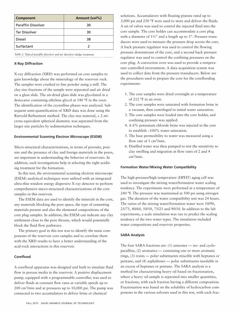
Several tests were conducted to determine the effect of H2Son the sludge/asphaltene precipitation and its stability. TheH2S tests were conducted using a closed system loop. H2S wasgenerated by reacting iron sulfide (FeS) with 10 wt% HCl acidin an erlenmeyer flask; the generated H2S gas was then di-verted to a second flask containing live 20 wt% HCl acid andthe LF oil at a 1:1 ratio with iron concentrations ranging from0 ppm to 1,000 ppm. After exposing the solution to H2S gas,the H2S was then diverted to a third flask containing cadmiumsulfate (CdSO4) where the H2S was scavenged completely intocadmium sulfide (CdS). The setup is shown in Fig. 1. The H2Sexperiments lasted 2 to 4 hours and the acid-oil was then fil-tered through 100 µm mesh size to determine the severity ofthe sludge/asphaltene.
Removal of Acid-Induced Sludge
The effectiveness of different mixtures of two solvents —
paraffin dissolver and tar dissolver — surfactant and diesel inremoving the acid-induced sludging material from the LF for-mation was explored. The sludge/asphaltene removal experi-ments were performed at a temperature of 140 °F andatmospheric pressure. The ratio of dissolver/sludging materialwas kept at 10:1 (mL:g). The duration of all conducted sludg-ing removal experiments was 4 hours.
Mud Cake Removal
The mud cake removal experiments were performed using anHPHT filter press cell. A nearly 200 mL representative sampleof the oil-based DIF used during LF drilling operations was in-troduced into the fluid loss cell. Using 3 µm ceramic disks as amedium, the filtration process was initiated by applying a dif-ferential pressure of 300 psi. This filtration process was con-tinued at 240 °F until the fluid loss reached a constant volume,indicating that a mud filter cake had been built on top of theceramic disk. The mud filter cake was then soaked in the acidtreatment for 4 hours under 240 °F and 300 psi. The weight ofthe formed mud cake was measured before and after it wassoaked in the clean out treatment acid. The recorded valueswere used to calculate the percentage of the cake weight lostdue to its interaction with the clean out treatment acid.
RESULTS AND DISCUSSION
Mineralogical and Rock Analysis
XRD analysis is necessary to screen the rock to eliminate anypossibility of acid-sensitive clays being present, such as excessamounts of chlorite or illite. The XRD results showed that thesamples consisted of carbonate minerals — calcite and ankerite— with minor quantities of clay minerals — kaolinite, I-S andillite — as well as sand — quartz — in some of the samples.Table 3 gives the chemical compounds of these minerals andothers common in the oil industry. Table 4 shows the bulkmineralogical composition of several core plugs from thisreservoir. The data indicated that calcite was the most domi-
Fig. 1. H2S generation setup used in testing the effect of H2S on sludge/asphaltene precipitation.
SAUDI ARAMCO JOURNAL OF TECHNOLOGY FALL 2015
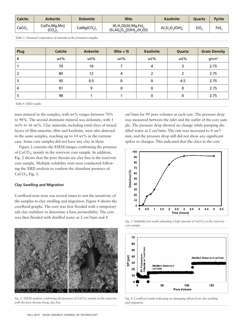
nant mineral in the samples, with wt% ranges between 70% to 98%. The second dominant mineral was dolomite, with 1wt% to 16 wt%. Clay minerals, including total clays of mixedlayers of illite-smectite, illite and kaolinite, were also detectedin the same samples, reaching up to 14 wt% in the extremecase. Some core samples did not have any clay in them.
Figure 2 contains the ESEM images confirming the presenceof CaCO3, mainly in the reservoir core sample. In addition,Fig. 2 shows that the pore throats are clay free in the reservoircore sample. Multiple solubility tests were conducted follow-ing the XRD analysis to confirm the abundant presence ofCaCO3, Fig. 3.
Clay Swelling and Migration
Coreflood tests were run several times to test the sensitivity ofthe samples to clay swelling and migration. Figure 4 shows thecoreflood graphs. The core was first flooded with a temporarysalt clay stabilizer to determine a base permeability. The corewas then flooded with distilled water at 2 cm3/min and 4
cm3/min for 90 pore volumes at each rate. The pressure dropwas measured between the inlet and the outlet of the core sam-ple. The pressure drop showed no change while pumping dis-tilled water at 2 cm3/min. The rate was increased to 4 cm3/min, and the pressure drop still did not show any significantspikes or changes. This indicated that the clays in the core
Fig. 2. ESEM analysis confirming the presence of CaCO3 mainly in the reservoir,with the pore throats being clay free.
Fig. 3. Solubility test result indicating a high amount of CaCO3 in the reservoircore sample.
Calcite Ankerite Dolomite Illite Kaolinite Quartz Pyrite
CaCO3
Ca(Fe,Mg,Mn)(CO3)2
CaMg(CO3)2
(K,H3O)(Al,Mg,Fe)2(Si,Al)4O10[(OH)2,(H2O)] Al2Si2O5(OH)4 SiO4 FeS2
Table 3. Chemical composition of minerals in the formation samples
Plug Calcite Ankerite Illite + IS Kaolinite Quartz Grain Density
# wt% wt% wt% wt% wt% g/cm3
1 70 16 7 4 3 2.75
2 80 12 4 2 2 2.75
3 95 0.5 0 0 4.5 2.75
4 91 9 0 0 0 2.75
5 98 1 1 0 0 2.75
T
Table 4. XRD results
Fig. 4. Coreflood results indicating no damaging effects from clay swellingand migration.
FALL 2015 SAUDI ARAMCO JOURNAL OF TECHNOLOGY
samples didn’t have major swelling or migrating effects thatwould hinder the flow of hydrocarbons.
Scale Analysis
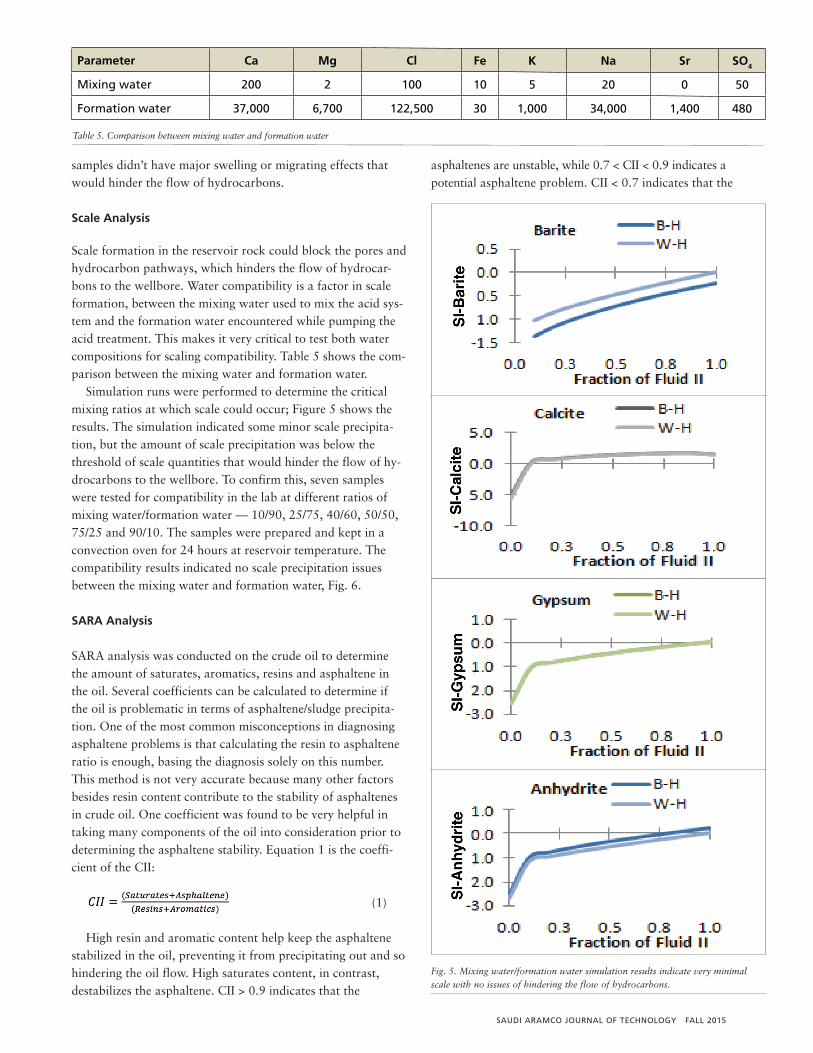
Scale formation in the reservoir rock could block the pores andhydrocarbon pathways, which hinders the flow of hydrocar-bons to the wellbore. Water compatibility is a factor in scaleformation, between the mixing water used to mix the acid sys-tem and the formation water encountered while pumping theacid treatment. This makes it very critical to test both watercompositions for scaling compatibility. Table 5 shows the com-parison between the mixing water and formation water.
Simulation runs were performed to determine the criticalmixing ratios at which scale could occur; Figure 5 shows theresults. The simulation indicated some minor scale precipita-tion, but the amount of scale precipitation was below thethreshold of scale quantities that would hinder the flow of hy-drocarbons to the wellbore. To confirm this, seven sampleswere tested for compatibility in the lab at different ratios ofmixing water/formation water — 10/90, 25/75, 40/60, 50/50,75/25 and 90/10. The samples were prepared and kept in aconvection oven for 24 hours at reservoir temperature. Thecompatibility results indicated no scale precipitation issues between the mixing water and formation water, Fig. 6.
SARA Analysis
SARA analysis was conducted on the crude oil to determinethe amount of saturates, aromatics, resins and asphaltene inthe oil. Several coefficients can be calculated to determine ifthe oil is problematic in terms of asphaltene/sludge precipita-tion. One of the most common misconceptions in diagnosingasphaltene problems is that calculating the resin to asphalteneratio is enough, basing the diagnosis solely on this number.This method is not very accurate because many other factorsbesides resin content contribute to the stability of asphaltenesin crude oil. One coefficient was found to be very helpful intaking many components of the oil into consideration prior todetermining the asphaltene stability. Equation 1 is the coeffi-cient of the CII:
(1)
High resin and aromatic content help keep the asphaltenestabilized in the oil, preventing it from precipitating out and sohindering the oil flow. High saturates content, in contrast,destabilizes the asphaltene. CII > 0.9 indicates that the
asphaltenes are unstable, while 0.7 < CII < 0.9 indicates a potential asphaltene problem. CII < 0.7 indicates that the
Parameter Ca Mg Cl Fe K Na Sr SO4
Mixing water 200 2 100 10 5 20 0 50
Formation water 37,000 6,700 122,500 30 1,000 34,000 1,400 480
Table 5. Comparison between mixing water and formation water
Fig. 5. Mixing water/formation water simulation results indicate very minimalscale with no issues of hindering the flow of hydrocarbons.
SAUDI ARAMCO JOURNAL OF TECHNOLOGY FALL 2015
asphaltenes are stable in the oil11. The CII calculated for theLF oil is 1.6, which indicates problematic oil in terms ofsludge/asphaltene precipitation. Table 6 shows the SARAanalysis results and CII calculation.
Acid-Oil Compatibility
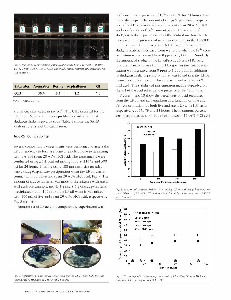
Several compatibility experiments were performed to assess theLF oil tendency to form a sludge or emulsion due to its mixingwith live and spent 20 wt% HCl acid. The experiments wereconducted using a 1:1 acid-oil mixing ratio at 240 °F and 500psi for 24 hours. Filtering using 100 µm mesh size revealedheavy sludge/asphaltene precipitation when the LF oil was incontact with both live and spent 20 wt% HCl acid, Fig. 7. Theamount of sludge material was more in the mixture with spentHCl acid; for example, nearly 6 g and 8.5 g of sludge materialprecipitated out of 100 mL of the LF oil when it was mixedwith 100 mL of live and spent 20 wt% HCl acid, respectively,Fig. 8 (far left).
Another set of LF acid-oil compatibility experiments was
performed in the presence of Fe3+ at 240 °F for 24 hours. Fig-ure 8 also depicts the amount of sludge/asphaltene precipita-tion after LF oil was mixed with live and spent 20 wt% HClacid as a function of Fe3+ concentration. The amount ofsludge/asphaltene precipitation in the acid-oil mixture clearlyincreased in the presence of iron. For example, in the 100/100mL mixture of LF oil/live 20 wt% HCl acid, the amount ofsludging material increased from 6 g to 8 g when the Fe3+ con-centration was increased from 0 ppm to 1,000 ppm. Similarly,the amount of sludge in the LF oil/spent 20 wt% HCl acidmixture increased from 8.5 g to 12.5 g when the iron concen-tration was increased from 0 ppm to 1,000 ppm. In additionto sludge/asphaltene precipitation, it was found that the LF oilformed a stable emulsion when it was mixed with 20 wt%HCl acid. The stability of this emulsion mainly depended onthe pH of the acid solution, the presence of Fe3+ and time.
Figures 9 and 10 show the percentage of acid separatedfrom the LF oil and acid emulsion as a function of time andFe3+ concentration for both live and spent 20 wt% HCl acid,respectively, at 140 °F and 24 hours. The maximum percent-age of separated acid for both live and spent 20 wt% HCl acid
Fig. 6. Mixing water/formation water compatibility tests 1 through 7 at 10/90,25/75, 40/60, 50/50, 60/40, 75/25 and 90/10 ratios, respectively, indicating noscaling issues.
Fig. 7. Asphaltenes/sludge precipitation after mixing LF oil with both live andspent 20 wt% HCl acid at 240 ºF for 24 hours.
Fig. 8. Amount of sludge/asphaltene after mixing LF oil with live (white bar) andspent (black bar) 20 wt% HCl acid as a function of Fe3+ concentration at 240 ºFfor 24 hours.
Fig. 9. Percentage of acid phase separated out of LF oil/live 20 wt% HCl acidemulsion at 1:1 mixing ratio and 140 ºF.
Saturates Aromatics Resins Asphaltenes CII
60.3 30.4 8.1 1.2 1.6
T
Table 6. SARA analysis
FALL 2015 SAUDI ARAMCO JOURNAL OF TECHNOLOGY
reached only 40% of the present acid amount in the LF oil andHCl acid emulsion. Compared to live 20 wt% HCl acid, theLF oil formed a more stable emulsion with spent 20 wt% HClacid. The maximum percentage of separated acid was reachedafter nearly one hour for the spent 20 wt% HCl acid/LF oilemulsion compared to only 10 minutes for the live 20 wt%HCl acid/LF oil emulsion. In addition to the pH value of theacid solution, it was found that the presence of Fe3+ stabilizedthe LF acid-oil emulsion.
The presence of Fe3+ up to 1,000 ppm had no effect on thestability of the LF oil/spent 20 wt% HCl acid emulsion. Forexample, the percentage of acid separated from the spent 20wt% HCl acid/LF oil emulsion after nearly one hour remainedconstant when the Fe3+ amount was increased from 0 ppm to1,000 ppm. In contrast, the presence of Fe3+ had a significantimpact on the stability of the LF oil emulsion with live 20 wt%HCl acid. The percentage of acid phase separated from thatacid-oil emulsion dropped from 40% to 0 ppm when the Fe3+
concentration increased from 0 ppm to 500 ppm. Furthermore, several H2S experiment results indicated that
a H2S and iron combination stabilized the sludge/asphaltene.Figure 11 shows the result of filtering the acid and oil after ex-posing it to 1,000 ppm iron and low concentrations of H2S for4 hours. The majority of the fluid failed to pass through the100 µm mesh size, which indicated that the sludge thicknessbecame more severe due to the combined effect of the H2S andiron on the sludge/asphaltene.
It is evident from the above results that the LF oil formssludging material and a stable acid emulsion when it is in con-tact with 20 wt% HCl acid, especially in the presence of Fe3+.Therefore, demulsifier, anti-sludge and iron control acid addi-tives were used in further tests. Citric acid, an iron controlagent, was used at 20 lb/gal to chelate nearly 2,500 ppm ofFe3+. The concentrations of both demulsifier and anti-sludgeagents were varied until no sludge/emulsion occurred when 20wt% HCl acid was mixed with the LF oil. Figures 12 and 13show that adding demulsifier agent at 5 gpt, anti-sludge agent
at 5 gpt and iron control agent at 20 lb/gal was effective inpreventing sludge precipitation and emulsion formation whenthe LF oil was mixed with 20 wt% HCl acid at a 1:1 ratio andat 140 °F.
Asphaltene/Sludge Removal
As mentioned, several LF wells had been previously stimulatedwith HCl acid without demulsifier and anti-sludge additives.The wells ceased to flow after the stimulation treatments.
Fig. 10. Percentage of acid phase separated out of LF oil/spent 20 wt% HCl acidemulsion at 1:1 mixing ratio and 140 ºF.
Fig. 11. Oil was run through 100 μm mesh size, then the acid-oil sludge mix thatwas generated in the presence of H2S and 1,000 ppm iron was poured on themesh, following that, hot water was poured on the mesh, and the remainingmaterial is thick sludge precipitation.
Fig. 12. Effect of adding different concentrations of demulsifier agent to the acid-oil mix (0 gpt to 15 gpt).
SAUDI ARAMCO JOURNAL OF TECHNOLOGY FALL 2015
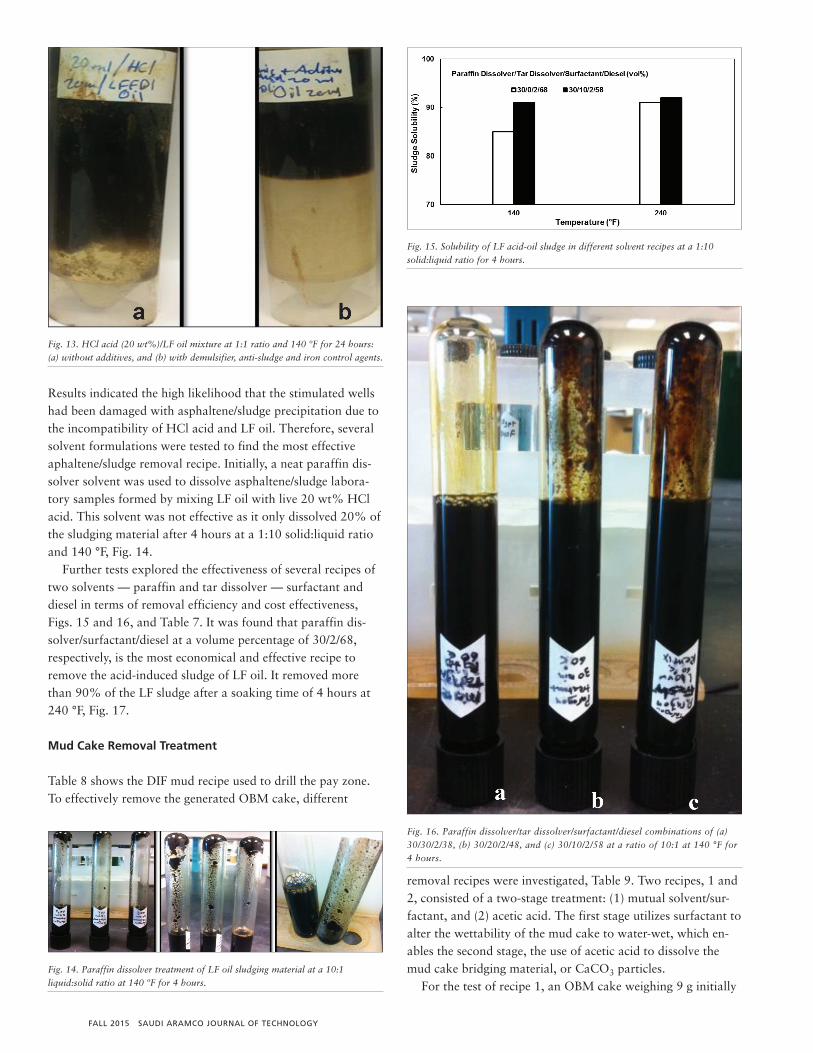
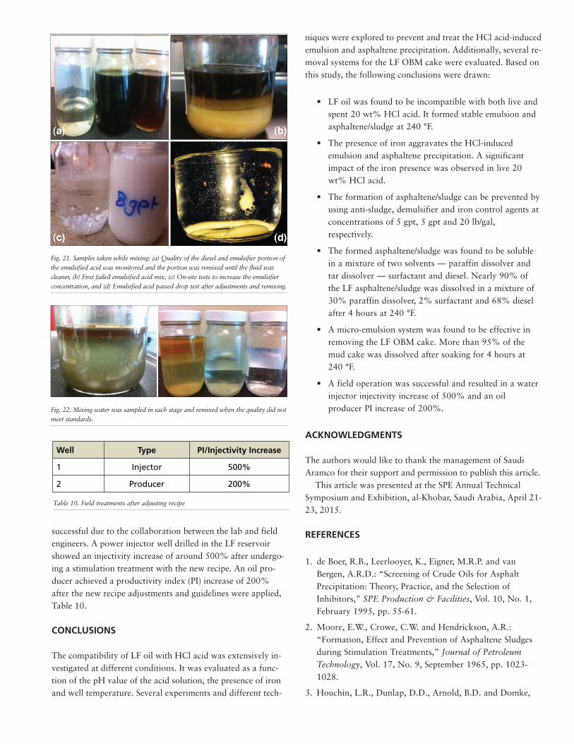
Results indicated the high likelihood that the stimulated wellshad been damaged with asphaltene/sludge precipitation due tothe incompatibility of HCl acid and LF oil. Therefore, severalsolvent formulations were tested to find the most effectiveaphaltene/sludge removal recipe. Initially, a neat paraffin dis-solver solvent was used to dissolve asphaltene/sludge labora-tory samples formed by mixing LF oil with live 20 wt% HClacid. This solvent was not effective as it only dissolved 20% ofthe sludging material after 4 hours at a 1:10 solid:liquid ratioand 140 °F, Fig. 14.
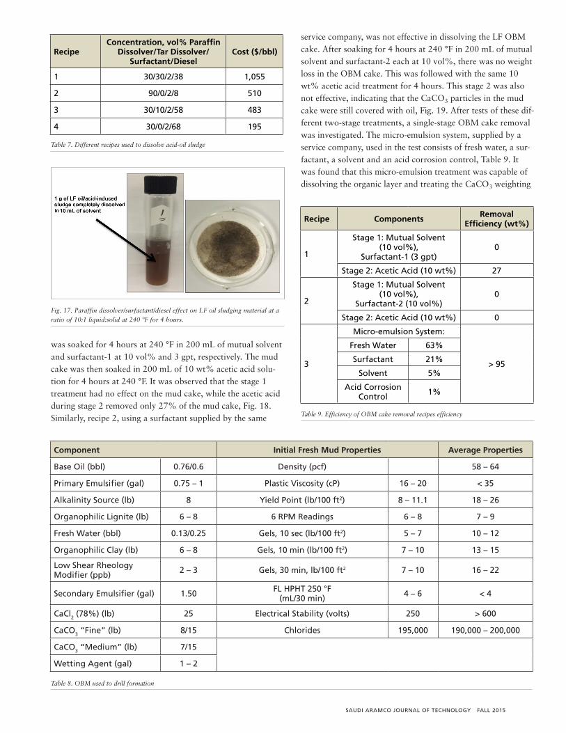
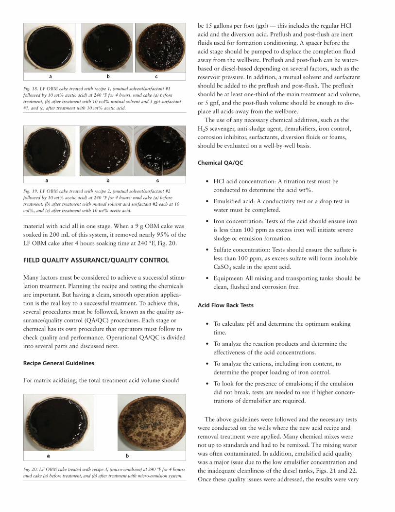
Further tests explored the effectiveness of several recipes oftwo solvents — paraffin and tar dissolver — surfactant anddiesel in terms of removal efficiency and cost effectiveness,Figs. 15 and 16, and Table 7. It was found that paraffin dis-solver/surfactant/diesel at a volume percentage of 30/2/68, respectively, is the most economical and effective recipe to remove the acid-induced sludge of LF oil. It removed morethan 90% of the LF sludge after a soaking time of 4 hours at240 °F, Fig. 17.
Mud Cake Removal Treatment
Table 8 shows the DIF mud recipe used to drill the pay zone.To effectively remove the generated OBM cake, different
removal recipes were investigated, Table 9. Two recipes, 1 and2, consisted of a two-stage treatment: (1) mutual solvent/sur-factant, and (2) acetic acid. The first stage utilizes surfactant toalter the wettability of the mud cake to water-wet, which en-ables the second stage, the use of acetic acid to dissolve themud cake bridging material, or CaCO3 particles.
For the test of recipe 1, an OBM cake weighing 9 g initially
Fig. 13. HCl acid (20 wt%)/LF oil mixture at 1:1 ratio and 140 ºF for 24 hours:(a) without additives, and (b) with demulsifier, anti-sludge and iron control agents.
Fig. 14. Paraffin dissolver treatment of LF oil sludging material at a 10:1liquid:solid ratio at 140 ºF for 4 hours.
Fig. 15. Solubility of LF acid-oil sludge in different solvent recipes at a 1:10solid:liquid ratio for 4 hours.
Fig. 16. Paraffin dissolver/tar dissolver/surfactant/diesel combinations of (a)30/30/2/38, (b) 30/20/2/48, and (c) 30/10/2/58 at a ratio of 10:1 at 140 °F for4 hours.
FALL 2015 SAUDI ARAMCO JOURNAL OF TECHNOLOGY
was soaked for 4 hours at 240 °F in 200 mL of mutual solventand surfactant-1 at 10 vol% and 3 gpt, respectively. The mudcake was then soaked in 200 mL of 10 wt% acetic acid solu-tion for 4 hours at 240 °F. It was observed that the stage 1treatment had no effect on the mud cake, while the acetic acidduring stage 2 removed only 27% of the mud cake, Fig. 18.Similarly, recipe 2, using a surfactant supplied by the same
service company, was not effective in dissolving the LF OBMcake. After soaking for 4 hours at 240 °F in 200 mL of mutualsolvent and surfactant-2 each at 10 vol%, there was no weightloss in the OBM cake. This was followed with the same 10wt% acetic acid treatment for 4 hours. This stage 2 was alsonot effective, indicating that the CaCO3 particles in the mudcake were still covered with oil, Fig. 19. After tests of these dif-ferent two-stage treatments, a single-stage OBM cake removalwas investigated. The micro-emulsion system, supplied by aservice company, used in the test consists of fresh water, a sur-factant, a solvent and an acid corrosion control, Table 9. Itwas found that this micro-emulsion treatment was capable ofdissolving the organic layer and treating the CaCO3 weighting
RecipeConcentration, vol% Paraffi n
Dissolver/Tar Dissolver/Surfactant/Diesel
Cost ($/bbl)
1 30/30/2/38 1,055
2 90/0/2/8 510
3 30/10/2/58 483
4 30/0/2/68 195
T
Table 7. Different recipes used to dissolve acid-oil sludge
Fig. 17. Paraffin dissolver/surfactant/diesel effect on LF oil sludging material at aratio of 10:1 liquid:solid at 240 ºF for 4 hours.
Component Initial Fresh Mud Properties Average Properties
Base Oil (bbl) 0.76/0.6 Density (pcf) 58 – 64
Primary Emulsifi er (gal) 0.75 – 1 Plastic Viscosity (cP) 16 – 20 < 35
Alkalinity Source (lb) 8 Yield Point (lb/100 ft2) 8 – 11.1 18 – 26
Organophilic Lignite (lb) 6 – 8 6 RPM Readings 6 – 8 7 – 9
Fresh Water (bbl) 0.13/0.25 Gels, 10 sec (lb/100 ft2) 5 – 7 10 – 12
Organophilic Clay (lb) 6 – 8 Gels, 10 min (lb/100 ft2) 7 – 10 13 – 15
Low Shear Rheology Modifi er (ppb) 2 – 3 Gels, 30 min, lb/100 ft2 7 – 10 16 – 22
Secondary Emulsifi er (gal) 1.50 FL HPHT 250 °F (mL/30 min) 4 – 6 < 4
CaCl2 (78%) (lb) 25 Electrical Stability (volts) 250 > 600
CaCO3 “Fine” (lb) 8/15 Chlorides 195,000 190,000 – 200,000
CaCO3 “Medium” (lb) 7/15
Wetting Agent (gal) 1 – 2
Table 8. OBM used to drill formation
Recipe Components Removal Effi ciency (wt%)
1
Stage 1: Mutual Solvent (10 vol%),
Surfactant-1 (3 gpt)0
Stage 2: Acetic Acid (10 wt%) 27
2
Stage 1: Mutual Solvent (10 vol%),
Surfactant-2 (10 vol%)0
Stage 2: Acetic Acid (10 wt%) 0
3
Micro-emulsion System:
> 95
Fresh Water 63%
Surfactant 21%
Solvent 5%
Acid Corrosion Control 1%
Table 9. Efficiency of OBM cake removal recipes efficiency
SAUDI ARAMCO JOURNAL OF TECHNOLOGY FALL 2015
material with acid all in one stage. When a 9 g OBM cake wassoaked in 200 mL of this system, it removed nearly 95% of theLF OBM cake after 4 hours soaking time at 240 °F, Fig. 20.
FIELD QUALITY ASSURANCE/QUALITY CONTROL
Many factors must be considered to achieve a successful stimu-lation treatment. Planning the recipe and testing the chemicalsare important. But having a clean, smooth operation applica-tion is the real key to a successful treatment. To achieve this,several procedures must be followed, known as the quality as-surance/quality control (QA/QC) procedures. Each stage orchemical has its own procedure that operators must follow tocheck quality and performance. Operational QA/QC is dividedinto several parts and discussed next.
Recipe General Guidelines
For matrix acidizing, the total treatment acid volume should
be 15 gallons per foot (gpf) — this includes the regular HClacid and the diversion acid. Preflush and post-flush are inertfluids used for formation conditioning. A spacer before theacid stage should be pumped to displace the completion fluidaway from the wellbore. Preflush and post-flush can be water-based or diesel-based depending on several factors, such as thereservoir pressure. In addition, a mutual solvent and surfactantshould be added to the preflush and post-flush. The preflushshould be at least one-third of the main treatment acid volume,or 5 gpf, and the post-flush volume should be enough to dis-place all acids away from the wellbore.
The use of any necessary chemical additives, such as theH2S scavenger, anti-sludge agent, demulsifiers, iron control,corrosion inhibitor, surfactants, diversion fluids or foams,should be evaluated on a well-by-well basis.
Chemical QA/QC
• HCl acid concentration: A titration test must beconducted to determine the acid wt%.
• Emulsified acid: A conductivity test or a drop test inwater must be completed.
• Iron concentration: Tests of the acid should ensure ironis less than 100 ppm as excess iron will initiate severesludge or emulsion formation.
• Sulfate concentration: Tests should ensure the suflate isless than 100 ppm, as excess sulfate will form insolubleCaSO4 scale in the spent acid.
• Equipment: All mixing and transporting tanks should beclean, flushed and corrosion free.
Acid Flow Back Tests
• To calculate pH and determine the optimum soakingtime.
• To analyze the reaction products and determine theeffectiveness of the acid concentrations.
• To analyze the cations, including iron content, todetermine the proper loading of iron control.
• To look for the presence of emulsions; if the emulsiondid not break, tests are needed to see if higher concen-trations of demulsifier are required.
The above guidelines were followed and the necessary testswere conducted on the wells where the new acid recipe and removal treatment were applied. Many chemical mixes werenot up to standards and had to be remixed. The mixing waterwas often contaminated. In addition, emulsified acid qualitywas a major issue due to the low emulsifier concentration andthe inadequate cleanliness of the diesel tanks, Figs. 21 and 22.Once these quality issues were addressed, the results were very
Fig. 18. LF OBM cake treated with recipe 1, (mutual solvent/surfactant #1followed by 10 wt% acetic acid) at 240 ºF for 4 hours: mud cake (a) beforetreatment, (b) after treatment with 10 vol% mutual solvent and 3 gpt surfactant#1, and (c) after treatment with 10 wt% acetic acid.
Fig. 19. LF OBM cake treated with recipe 2, (mutual solvent/surfactant #2followed by 10 wt% acetic acid) at 240 ºF for 4 hours: mud cake (a) beforetreatment, (b) after treatment with mutual solvent and surfactant #2 each at 10vol%, and (c) after treatment with 10 wt% acetic acid.
Fig. 20. LF OBM cake treated with recipe 3, (micro-emulsion) at 240 ºF for 4 hours:mud cake (a) before treatment, and (b) after treatment with micro-emulsion system.
successful due to the collaboration between the lab and fieldengineers. A power injector well drilled in the LF reservoirshowed an injectivity increase of around 500% after undergo-ing a stimulation treatment with the new recipe. An oil pro-ducer achieved a productivity index (PI) increase of 200%after the new recipe adjustments and guidelines were applied,Table 10.
CONCLUSIONS
The compatibility of LF oil with HCl acid was extensively in-vestigated at different conditions. It was evaluated as a func-tion of the pH value of the acid solution, the presence of ironand well temperature. Several experiments and different tech-
niques were explored to prevent and treat the HCl acid-inducedemulsion and asphaltene precipitation. Additionally, several re-moval systems for the LF OBM cake were evaluated. Based onthis study, the following conclusions were drawn:
• LF oil was found to be incompatible with both live andspent 20 wt% HCl acid. It formed stable emulsion andasphaltene/sludge at 240 °F.
• The presence of iron aggravates the HCl-inducedemulsion and asphaltene precipitation. A significantimpact of the iron presence was observed in live 20wt% HCl acid.
• The formation of asphaltene/sludge can be prevented byusing anti-sludge, demulsifier and iron control agents atconcentrations of 5 gpt, 5 gpt and 20 lb/gal,respectively.
• The formed asphaltene/sludge was found to be solublein a mixture of two solvents — paraffin dissolver andtar dissolver — surfactant and diesel. Nearly 90% ofthe LF asphaltene/sludge was dissolved in a mixture of30% paraffin dissolver, 2% surfactant and 68% dieselafter 4 hours at 240 °F.
• A micro-emulsion system was found to be effective inremoving the LF OBM cake. More than 95% of themud cake was dissolved after soaking for 4 hours at240 °F.
• A field operation was successful and resulted in a waterinjector injectivity increase of 500% and an oilproducer PI increase of 200%.
ACKNOWLEDGMENTS
The authors would like to thank the management of SaudiAramco for their support and permission to publish this article.
This article was presented at the SPE Annual TechnicalSymposium and Exhibition, al-Khobar, Saudi Arabia, April 21-23, 2015.
REFERENCES
1. de Boer, R.B., Leerlooyer, K., Eigner, M.R.P. and vanBergen, A.R.D.: “Screening of Crude Oils for AsphaltPrecipitation: Theory, Practice, and the Selection ofInhibitors,” SPE Production & Facilities, Vol. 10, No. 1,February 1995, pp. 55-61.
2. Moore, E.W., Crowe, C.W. and Hendrickson, A.R.:“Formation, Effect and Prevention of Asphaltene Sludgesduring Stimulation Treatments,” Journal of PetroleumTechnology, Vol. 17, No. 9, September 1965, pp. 1023-1028.
3. Houchin, L.R., Dunlap, D.D., Arnold, B.D. and Domke,
Well Type PI/Injectivity Increase
1 Injector 500%
2 Producer 200%
T Table 10. Field treatments after adjusting recipe
Fig. 21. Samples taken while mixing: (a) Quality of the diesel and emulsifier portion ofthe emulsified acid was monitored and the portion was remixed until the fluid wascleaner, (b) First failed emulsified acid mix, (c) On-site tests to increase the emulsifierconcentration, and (d) Emulsified acid passed drop test after adjustments and remixing.
Fig. 22. Mixing water was sampled in each stage and remixed when the quality did notmeet standards.
BIOGRAPHIES
Tariq A. Al-Mubarak is a PetroleumEngineer with the Formation Damageand Stimulation Unit of SaudiAramco’s Exploration and PetroleumEngineering Center – AdvancedResearch Center (EXPEC ARC). Priorto joining this unit, his experience
included work with Saudi Aramco’s Gas ReservoirManagement Department, Schlumberger’s fieldengineering/research lab in Louisiana and theundergraduate research summer program at Texas A&MUniversity. During these years, Tariq participated in manyprojects that included gas field management, matrixacidizing, damage removal, acid fracturing and hydraulicfracturing along with attending many stimulation fieldQA/QC jobs.
He is an active member of the Society of PetroleumEngineers (SPE) and strongly advocates for youngprofessionals to shape the future of the oil and gasindustry. Tariq has published 10 SPE papers and filed oneU.S. patent.
In 2013 and 2014, he received the SPE Best TechnicalPaper award, winning first place in both the 3rd and 4th
SPE-SAS technical paper contests.Tariq received his B.S. degree with honors in Petroleum
Engineering from Texas A&M University, College Station,TX.
Dr. Mohammed H. Al-Khaldi joinedSaudi Aramco in 2001 as a ResearchEngineer working in Saudi Aramco’sExploration and PetroleumEngineering Center – AdvancedResearch Center (EXPEC ARC). Sincethis time, he has been responsible for
evaluating different stimulation treatments, conductingseveral research studies and investigating severalstimulation fluids. In addition, Mohammed was involved inthe design of acid fracturing treatments. As an award forhis efforts, he received the Vice President’s RecognitionAward for significant contributions to the safe andsuccessful completion of the first 100 fracturing treatments.Mohammed’s research interests include well stimulation,formation damage mitigation and conformance control.
He is an active member of the Society of PetroleumEngineers (SPE). Mohammed has published more than 15SPE papers and seven journal articles, and has two patents.In 2011, he received the SPE Best Technical Paper Award,winning first place in the 2nd GCC SPE paper contest.
He received his B.S. degree in Chemical Engineering(with First Class Honors) from King Fahd University ofPetroleum and Minerals (KFUPM), Dhahran, Saudi Arabia.Mohammed also received his M.S. and Ph.D. degrees inPetroleum Engineering (with First Class Honors) fromAdelaide University, Adelaide, Australia.
K.M.: “The Occurrence and Control of Acid-InducedAsphaltene Sludge,” SPE paper 19410, presented at theSPE Formation Damage Control Symposium, Lafayette,Louisiana, February 22-23, 1990.
4. Barker, K.M. and Newberry, M.E.: “Inhibition andRemoval of Low-pH Fluid-Induced Asphaltic SludgeFouling of Formations in Oil and Gas Wells,” SPE paper102738, presented at the International Symposium on OilField Chemistry, Houston, Texas, February 28 - March 2,2007.
5. Strassner, J.E.: “Effect of pH on Interfacial Films andStability of Crude Oil-Water Emulsions,” Journal ofPetroleum Technology, Vol. 20, No. 3, March 1968, pp.303-312.
6. Bobra, M.A.: “A Study of the Formation of Water-in-OilEmulsions,” Proceedings of the 13th Arctic and Marine OilSpill Program Technical Seminar, Edmonton, Alberta,Canada, June 6-8, 1990, 485 p.
7. Fingas, M.F., Fieldhouse, B., Bobra, M.A. and Tennyson,E.J.: “The Physics and Chemistry of Emulsions,”Proceedings of the Workshop on Emulsions, Marine SpillResponse Corporation, Washington, D.C., 1993, 11 p.
8. Mason, S.D., et al.: “e-Methodology for Selection ofWellbore Cleanup Techniques in Open Hole HorizontalCompletions,” SPE paper 68957, presented at the SPEEuropean Formation Damage Conference, The Hague, TheNetherlands, May 21-22, 2001.
9. Crowe, C.W., McGowan, G.R. and Baranet, S.E.:“Investigation of Retarded Acids Provides BetterUnderstanding of Their Effectiveness and PotentialBenefits,” SPE Production Engineering, Vol. 5, No. 2, May1990, pp. 166-170.
10. Fan, T., Wang, J. and Buckley, J.: “Evaluating Crude Oils by SARA Analysis,” SPE paper 75228, presented at the SPE/DOE Improved Oil Recovery Symposium, Tulsa, Oklahoma, April 13-17, 2002.
11. Yen, A., Yin, Y.R. and Asomaning, S.: “Evaluating Asphaltene Inhibitors: Laboratory Tests and Field Studies,” SPE paper 65376, presented at the SPE International Symposium on Oil Field Chemistry, Houston, Texas, February 13-16, 2001.
FALL 2015 SAUDI ARAMCO JOURNAL OF TECHNOLOGY
Omar Al-Dajani is a PetroleumEngineer with the Drilling Technologyteam of Saudi Aramco’s Explorationand Petroleum Engineering Center –Advanced Research Center (EXPECARC). Upon joining Saudi Aramco, hestarted rotating assignments with the
Offshore Drilling Department where he worked as aDrilling Engineer, writing several oil and gas well drillingprograms as well as witnessing critical jobs in the field.Omar also worked as a full-time Tool Pusher in the field,overseeing the safe execution of drilling programs. His nextassignment was with the Northern Area ProductionEngineering and Well Services Department as a ProductionEngineer assigned to the AFK Production Engineering Unit,where he ensured the target rate and API blend were safelyand properly met.
Omar received his B.S. degree with honors in PetroleumEngineering, with a minor in Geology, from Texas A&MUniversity, College Station, TX. Currently, he is pursuinghis M.S. degree in Geotechnical Engineering andGeomechanics at MIT, Cambridge, MA.
Hussain A. Al-Ibrahim is a PetroleumEngineer with the Formation Damageand Stimulation Unit of SaudiAramco’s Exploration and PetroleumEngineering Center – AdvancedResearch Center (EXPEC ARC). He ispassionate about projects related to
drill-in fluid evaluation and filter cake removal evaluation,such as evaluating different acid precursors, chelatingagents, micro-emulsion fluids and organic acids. Hussainhas also worked in the area of evaluating differenttreatments for condensate banking problems, asphaltenedeposition and scaling potential.
He has been an active part for the last 7 years of a teamthat promotes behavioral based safety. Hussain has alsotrained many young professionals and technicians on usingvarious pieces of equipment and conducting differentformation damage-related experiments. He also coauthoredfour Society of Petroleum Engineers (SPE) papers.
Hussain received his B.S. degree in PetroleumEngineering from King Fahd University of Petroleum andMinerals (KFUPM), Dhahran, Saudi Arabia, and iscurrently pursuing an M.S. degree in the same field.
Majid M. Rafie is a Field ProductionEngineer in Saudi Aramco’s SouthernArea Production EngineeringDepartment. Before he joined SaudiAramco, his experience includedworking with Baker Hughes inHouston, TX, as a Field Engineer for
unconventional wells. Majid enjoys working on artificiallift techniques, such as electrical submersible pumps. Healso is interested in the areas of multistage acid fracturingand matrix acidizing.
Majid participates in many Society of PetroleumEngineers (SPE) events and has published three SPE papers.
He received his B.S. degree in Petroleum Engineeringfrom Texas A&M University, College Station, TX.
SAUDI ARAMCO JOURNAL OF TECHNOLOGY FALL 2015


![Chemical Sequestration of CO by CaCO Dissolution...Pacific [CO. 3] Upper Sed. CaCO. 3. The ocean and atmosphere will react to excess CO. 2. emissions by reacting it with CaCO. 3. sediments](https://img.pdfslide.us/doc/110x75/5e9513f96f11a86fd534117d/chemical-sequestration-of-co-by-caco-dissolution-pacific-co-3-upper-sed.jpg)