Embed Size (px)
Citation preview
Energy Procedia 37 ( 2013 ) 1863 – 1870
1876-6102 © 2013 The Authors. Published by Elsevier Ltd.Selection and/or peer-review under responsibility of GHGTdoi: 10.1016/j.egypro.2013.06.066
GHGT-11
A Guide to Evaluate Solvents and Processes for Post-Combustion CO2
Capture
Paul M. Mathias, Satish Reddy, Arnold Smith, Kash Afshar
Fluor Corporation, 3 Polaris Way, Aliso Viejo, CA 92698
Abstract
The CO2-capture literature is difficult to follow because the number of papers and patents has exploded, and the claims of the authors are difficult to substantiate. From a beginning in the early 90s with just a handful of papers each year, the number of yearly papers has grown exponentially, reaching almost 1,000 publications in 2011. If this exponential rate of increase continues – and there is reason to believe that it will do so – the number of yearly publications will exceed 10,000 before 2020! The number of patents shows a similarly explosive growth. We believe that scientists and engineers who follow this important technology will be aided if they had some structure to guide them, and this paper represents our attempt to initiate the development of such guidelines.
© 2013 The Authors. Published by Elsevier Ltd. Selection and/or peer-review under responsibility of GHGT
Keywords: CO2 capture, chemical solvent; heat of solution; solvent evaluation, process innovations
1. Introduction
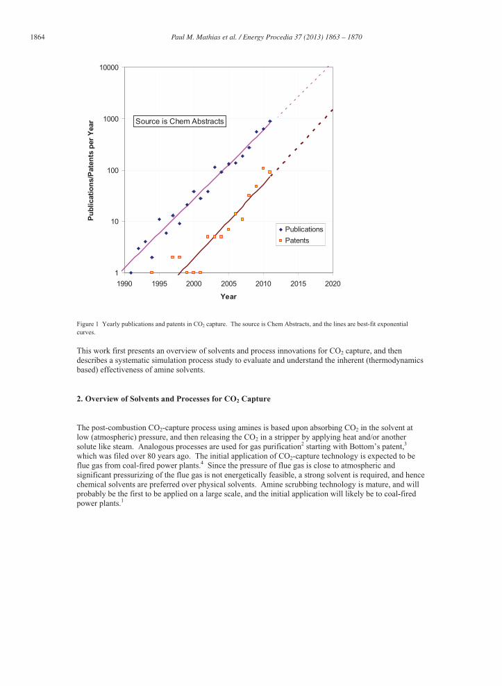
The CO2-capture technical literature began in the early 1990s, and the growth has been exponential over these past two decades. Figure 1 shows that the number of publications was almost 1,000 in 2011, and is projected to exceed 10,000 by 2020 if exponential extrapolation is applicable. The number of patents exhibits similar exponential growth, delayed by a period of about 7-10 years. We believe that scientists and engineers who attempt to follow this important process technology will be aided if they had some guidelines to follow, and this paper represents our attempt to initiate the development of such guidelines. Post-combustion capture of CO2 using amine solvents is likely to be the dominant CO2-capture technology for the medium term,1 and hence we limit our analysis to this process technology.
Available online at www.sciencedirect.com
© 2013 The Authors. Published by Elsevier Ltd.Selection and/or peer-review under responsibility of GHGT
1864 Paul M. Mathias et al. / Energy Procedia 37 ( 2013 ) 1863 – 1870
1
10
100
1000
10000
1990 1995 2000 2005 2010 2015 2020
Year
Pu
blic
atio
ns/
Pat
ents
per
Yea
r
Publications
Patents
Source is Chem Abstracts
Figure 1 Yearly publications and patents in CO2 capture. The source is Chem Abstracts, and the lines are best-fit exponential curves.
This work first presents an overview of solvents and process innovations for CO2 capture, and then describes a systematic simulation process study to evaluate and understand the inherent (thermodynamics based) effectiveness of amine solvents.
2. Overview of Solvents and Processes for CO2 Capture
The post-combustion CO2-capture process using amines is based upon absorbing CO2 in the solvent at low (atmospheric) pressure, and then releasing the CO2 in a stripper by applying heat and/or another solute like steam. Analogous processes are used for gas purification2 starting with Bottom’s patent,3
which was filed over 80 years ago. The initial application of CO2-capture technology is expected to be flue gas from coal-fired power plants.4 Since the pressure of flue gas is close to atmospheric and significant pressurizing of the flue gas is not energetically feasible, a strong solvent is required, and hence chemical solvents are preferred over physical solvents. Amine scrubbing technology is mature, and will probably be the first to be applied on a large scale, and the initial application will likely be to coal-fired power plants.1
Paul M. Mathias et al. / Energy Procedia 37 ( 2013 ) 1863 – 1870 1865
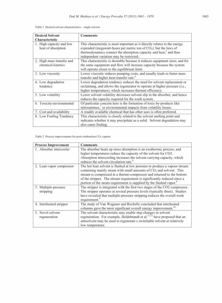
Table 1 Desired solvent characteristics – single solvent
Desired Solvent Characteristic
Comments
1. High capacity and low heat of absorption
This characteristic is most important as it directly relates to the energy expended (megawatt-hours per metric ton of CO2), but the laws of thermodynamics connect the absorption capacity and heat,5 and thus independent variation may be restricted.
2. High mass transfer and chemical kinetics
This characteristic is desirable because it reduces equipment sizes, and for the same equipment and flow will increase capacity because the system will operate closer to the equilibrium limit.
3. Low viscosity Lower viscosity reduces pumping costs, and usually leads to faster mass transfer and higher heat-transfer rate.6
4. Low degradation tendency
Lower degradation tendency reduces the need for solvent replacement or reclaiming, and allows the regenerator to operate at higher pressure (i.e., higher temperature), which increases thermal efficiency.
5. Low volatility Lower solvent volatility decreases solvent slip in the absorber, and hence reduces the capacity required for the wash system.
6. Toxicity/environmental Of particular concern here is the formation of toxic by-products like nitrosamines,7 or environmental impacts from volatility losses.
7. Cost and availability A readily available chemical that has other uses is often preferred. 8. Low Fouling Tendency This characteristic is closely related to the solvent melting point and
indicates whether it may precipitate as a solid. Solvent degradation may also cause fouling.
Table 2 Process improvements for post-combustion CO2 capture
Process Improvement Comments 1. Absorber intercooler The absorber heats up since absorption is an exothermic process, and
higher temperatures reduce the capacity of the solvent for CO2. Absorption intercooling increases the solvent carrying capacity, which reduces the solvent circulation rate.8
2. Lean-vapor compressor The hot lean solvent is flashed at low pressure to produce a vapour stream containing mainly steam with small amounts of CO2 and solvent. This stream is compressed in a thermo-compressor and returned to the bottom of the stripper. The stream requirement is significantly reduced since a portion of the steam requirement is supplied by the flashed vapor.8
3. Multiple-pressure stripping
The stripper is integrated with the first two stages of the CO2 compressor. The stripper operates at several pressure levels (typically three). Studies have revealed that multiple-pressure stripping reduces the overall work requirement.9
4. Interheated stripper The study of Van Wagener and Rochelle concluded that interheated columns gave the most significant overall energy improvement.10
5. Novel solvent regeneration
The solvent characteristic may enable step changes in solvent regeneration. For example, Heldebrandt et al.11,12 have proposed that an antisolvent may be used to regenerate s switchable solvent at relatively low temperature.
1866 Paul M. Mathias et al. / Energy Procedia 37 ( 2013 ) 1863 – 1870
Table 1 lists the desired characteristics of a CO2-capture solvent, and provides a brief comment on each one. In this work we focus on the first characteristic because it is the most important.
Table 2 summarizes key process enhancements that have either improved the efficiency of post-combustion CO2 capture or promise improvements in the future. Most of these enhancements are largely independent of the particular solvent, but other enhancements (e.g., #5) require specific features of the solvent. However, process improvements confuse the evaluation of solvents. In this work, we evaluate solvents by keeping the process specifications constant.
3. Solvent Study: Evaluation of the Effects of CO2 Capacity and Heat of Absorption
Theoretical and experimental approaches have been used to find the “best” solvent for CO2 capture. Xie et al.13 built upon the earlier work of Chakraborty et al.,14 and used ab initio computational chemistry to identify the best balance between chemical reaction extent and the energy of regeneration. Chowdhury et al.15 synthesized nine secondary and tertiary amines to find a target solvent with high absorption and low heat of reaction. Researchers have generally assumed that the goal is to identify solvents with large capacity and low heat of regeneration. We propose and use a third approach, which invents artificial solvents that have a systematic variation in CO2 capacity and heat of solution, and test these solvents in an Aspen Plus simulation model. We hope that our approach will improve the understanding of the performance of proposed solvents, and fine-tune our ability to identify and evaluate new solvents.
Table 3 Solvents used to understand correlation between CO2 capacity and enthalpy of solution
ID Formula Molecular Weight Name MDEA C5H13NO2 119.2 Methyldiethanolamine TEA C6H15NO3 149.2 Triethanolamine AMP C4H11NO 89.1 1-Propanol, 2-amino-2-methyl- NH3 H3N 17.0 Ammonia MEA C2H7NO 61.1 Monoethanolamine PZ C4H10N2 86.1 Piperazine DGA C4H11NO2 105.1 Diglycolamine
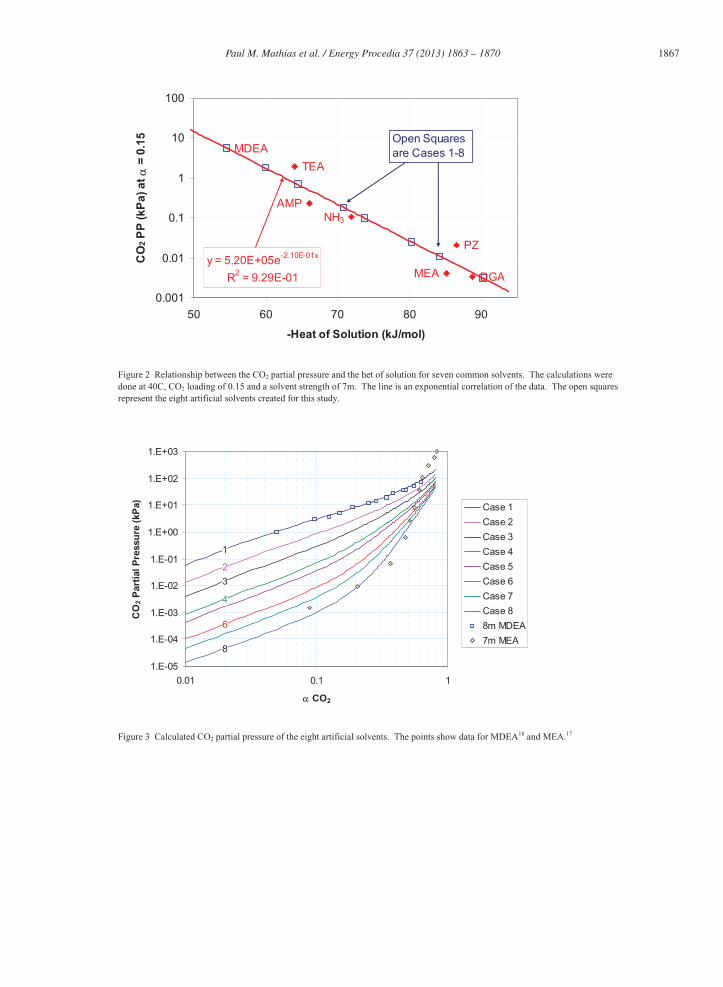
The seven common CO2-capture solvents presented in Table 3 were used to understand and quantify the relationship between the CO2 capacity and the enthalpy of solution; the solvents are listed approximately in the order of increasing magnitude of heat of solution. For the purpose of standardization, a representative condition of 40˚C, CO2 loading of 0.15, and a solvent strength of 7m was chosen. The thermodynamic models for the seven solvents were standard models from the AspenTech support web site,16 or were developed by the present authors through data regression of VLE data. The solvents covered a range of primary to tertiary amines, yet Figure 2 indicates that there appears to be a simple relationship between the solvent strength and its heat of solution, i.e., solvents with a higher CO2 capacity (low CO2 partial pressure) have a larger heat of solution. We have used this relationship to “invent” solvents that can be readily studied in a standardized process model. Primary amines like MEA and DGA form stable carbamates, and hence only half a mole of CO2 is absorbed per mole of amine, whereas tertiary amines (MDEA and TEA) and hindered amines (AMP) do not form stable carbamates, and hence can absorb up to one mol of CO2 per mole of amine.15 The eight artificial solvents shown in Figure 2 were created by modifying the parameters (specifically the enthalpy and Gibbs energy of formation at infinite dilution in water of the amine cation) of the AspenTech MDEA model, and thus they effectively behave as tertiary or hindered mines.
Paul M. Mathias et al. / Energy Procedia 37 ( 2013 ) 1863 – 1870 1867
DGAMEA
PZ
NH3
AMP
TEA
MDEA
y = 5.20E+05e-2.10E-01x
R2 = 9.29E-01
0.001
0.01
0.1
1
10
100
50 60 70 80 90
-Heat of Solution (kJ/mol)
CO
2 P
P (k
Pa)
at �
= 0
.15 Open Squares
are Cases 1-8
Figure 2 Relationship between the CO2 partial pressure and the het of solution for seven common solvents. The calculations were done at 40C, CO2 loading of 0.15 and a solvent strength of 7m. The line is an exponential correlation of the data. The open squares represent the eight artificial solvents created for this study.
1
2
3
4
6
8
1.E-05
1.E-04
1.E-03
1.E-02
1.E-01
1.E+00
1.E+01
1.E+02
1.E+03
0.01 0.1 1
� CO2
CO
2 P
arti
al P
ress
ure
(kP
a) Case 1
Case 2
Case 3
Case 4
Case 5
Case 6
Case 7
Case 8
8m MDEA
7m MEA
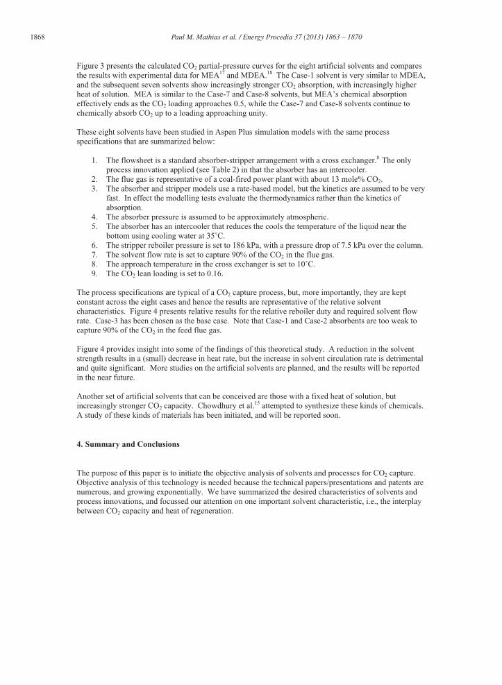
Figure 3 Calculated CO2 partial pressure of the eight artificial solvents. The points show data for MDEA18 and MEA.17
1868 Paul M. Mathias et al. / Energy Procedia 37 ( 2013 ) 1863 – 1870
Figure 3 presents the calculated CO2 partial-pressure curves for the eight artificial solvents and compares the results with experimental data for MEA17 and MDEA.18 The Case-1 solvent is very similar to MDEA, and the subsequent seven solvents show increasingly stronger CO2 absorption, with increasingly higher heat of solution. MEA is similar to the Case-7 and Case-8 solvents, but MEA’s chemical absorption effectively ends as the CO2 loading approaches 0.5, while the Case-7 and Case-8 solvents continue to chemically absorb CO2 up to a loading approaching unity.
These eight solvents have been studied in Aspen Plus simulation models with the same process specifications that are summarized below:
1. The flowsheet is a standard absorber-stripper arrangement with a cross exchanger.8 The only process innovation applied (see Table 2) in that the absorber has an intercooler.
2. The flue gas is representative of a coal-fired power plant with about 13 mole% CO2.3. The absorber and stripper models use a rate-based model, but the kinetics are assumed to be very
fast. In effect the modelling tests evaluate the thermodynamics rather than the kinetics of absorption.
4. The absorber pressure is assumed to be approximately atmospheric. 5. The absorber has an intercooler that reduces the cools the temperature of the liquid near the
bottom using cooling water at 35˚C.6. The stripper reboiler pressure is set to 186 kPa, with a pressure drop of 7.5 kPa over the column. 7. The solvent flow rate is set to capture 90% of the CO2 in the flue gas. 8. The approach temperature in the cross exchanger is set to 10˚C.9. The CO2 lean loading is set to 0.16.
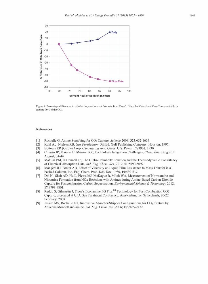
The process specifications are typical of a CO2 capture process, but, more importantly, they are kept constant across the eight cases and hence the results are representative of the relative solvent characteristics. Figure 4 presents relative results for the relative reboiler duty and required solvent flow rate. Case-3 has been chosen as the base case. Note that Case-1 and Case-2 absorbents are too weak to capture 90% of the CO2 in the feed flue gas.
Figure 4 provides insight into some of the findings of this theoretical study. A reduction in the solvent strength results in a (small) decrease in heat rate, but the increase in solvent circulation rate is detrimental and quite significant. More studies on the artificial solvents are planned, and the results will be reported in the near future.
Another set of artificial solvents that can be conceived are those with a fixed heat of solution, but increasingly stronger CO2 capacity. Chowdhury et al.15 attempted to synthesize these kinds of chemicals. A study of these kinds of materials has been initiated, and will be reported soon.
4. Summary and Conclusions
The purpose of this paper is to initiate the objective analysis of solvents and processes for CO2 capture. Objective analysis of this technology is needed because the technical papers/presentations and patents are numerous, and growing exponentially. We have summarized the desired characteristics of solvents and process innovations, and focussed our attention on one important solvent characteristic, i.e., the interplay between CO2 capacity and heat of regeneration.
Paul M. Mathias et al. / Energy Procedia 37 ( 2013 ) 1863 – 1870 1869
Duty
Flow Rate
-70
-60
-50
-40
-30
-20
-10
0
10
20
30
60 65 70 75 80 85 90 95 100
Solvent Heat of Solution (kJ/mol)
% D
iffe
ren
ce in
Rat
e fr
om
Bas
e C
ase
Figure 4 Percentage differences in reboiler duty and solvent flow rate from Case-3. Note that Case-1 and Case-2 were not able to capture 90% of the CO2.
References
[1] Rochelle G, Amine Scrubbing for CO2 Capture. Science 2009; 325:652-1654 [2] Kohl AL, Nielsen RB, Gas Purification, 5th Ed. Gulf Publishing Company: Houston; 1997. [3] Bottoms RR (Girdler Corp.), Separating Acid Gases, U.S. Patent 1783901, 1930 [4] Ciferno JP, Marano JJ, Munson RK, Technology Integration Challenges, Chem. Eng. Prog 2011,
August, 34-44. [5] Mathias PM, O’Connell JP, The Gibbs-Helmholtz Equation and the Thermodynamic Consistency
of Chemical Absorption Data, Ind. Eng. Chem. Res. 2012, 51:5090-5097. [6] Mangers RJ, Ponter AB, Effect of Viscosity on Liquid Film Resistance to Mass Transfer in a
Packed Column, Ind. Eng. Chem. Proc. Des. Dev. 1980, 19:530-537. [7] Dai N, Shah AD, Hu L, Plewa MJ, McKague B, Mitch WA, Measurement of Nitrosamine and
Nitramine Formation from NOx Reactions with Amines during Amine-Based Carbon Dioxide Capture for Postcombustion Carbon Sequestration, Environmental Science & Technology 2012, 17:9793-9801.
[8] Reddy S, Gilmartin J, Fluor’s Econamine FG PlusSM Technology for Post-Combustion CO2 Capture, presented at GPA Gas Treatment Conference, Amsterdam, the Netherlands, 20-22 February, 2008
[9] Jassim MS, Rochelle GT, Innovative Absorber/Stripper Configurations for CO2 Capture by Aqueous Monoethanolamine, Ind. Eng. Chem. Res. 2006; 45:2465-2472.
1870 Paul M. Mathias et al. / Energy Procedia 37 ( 2013 ) 1863 – 1870
[10] Van Wagener DH, Rochelle GT, Stripper Configurations for CO2 Capture by Aqueous
Monoethanolamine, Chem. Eng. Res. Des. 2011; 89:1639-1646. [11] Jessop PG, Mercer SM, Heldebrant GJ, CO2-Triggered Switchable Solvents, Surfactants, and Other
Materials, Energy & Environmental Science 2012; 6:7240-7253. [12] Heldebrant DJ, Zheng F, Koech PK, Zwoster A, Zhang J, Humble P, Howard C, Elliot M, Freeman
C, Tegrotenhuis W, CO2-Binding Organic Liquids, Enhanced CO2 Capture Process with Polarity-Swing-Assisted Regeneration, presented at the 243rd ACS National Meeting & Exposition, San Diego, March 25-29, 2012.
[13] Xie H-B, Johnson JK, Perry RJ, Genovese S, Wood BR, A Computational Study of the Heats of Reaction of Substituted Monoethanolamine with CO2, J. Phys. Chem. 2011, 115:342-350.
[14] Chakraborty AK, Bischoff KB, Astarita G, Damewood, Jr. JR, Molecular Orbital Approach to Substituent Effects in Amine-C02 Interactions, J. Am. Chem. Soc. 1988, 110:6947-6954.
[15] Chowdhury FA, Okabe H, Yamada H, Onoda M, Fujioka Y, Synthesis and Selection of Hindered New Amine Adsorbents for CO2 Capture. Energy Procedia 2011; 4: 201-208.
[16] http://support.aspentech.com/ [17] Jou F-Y, Mather AE, Otto FD, The Solubility of CO2 in 30 Mass Percent Monoethanolamine
Solution. Can. J. Chem. Eng. 1995, 73:140-147. [18] Ermatchkov V, Kamps AA, Maurer G, Solubility of Carbon Dioxide in Aqueous Solutions of N-
Methyldiethanolamine in the Low Gas Loading Region, Ind. Eng. Chem. Res. 2006, 45:6081-6091.