Embed Size (px)
Citation preview

Gas-FACTS project: Gas - Future Advanced Capture Technology SystemsWP 2.1: Gas-Specific Solvents
2nd Post Combustion Capture ConferenceSession 3: 2nd & 3rd Generation
Capture Technologies
Selection and Development of Specific Solvents for CO Capture from Specific Solvents for CO2 Capture from
Natural Gas Power Systems:
monophasic & biphasic monophasic & biphasic
Jiafei Zhang, Paul Fennell, Martin Truslerg
Bergen, 18th Sept. 2013
OutlineOutline
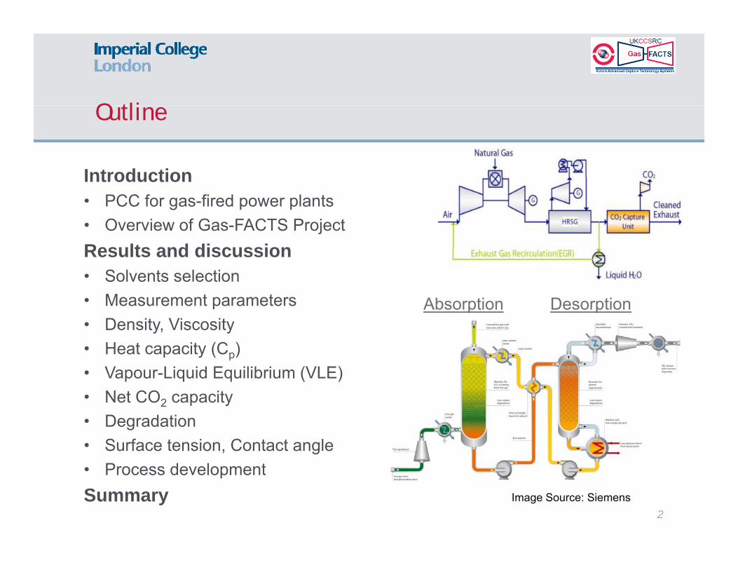
IntroductionIntroduction• PCC for gas-fired power plants• Overview of Gas-FACTS Project Results and discussionResults and discussion • Solvents selection • Measurement parameters
Densit ViscositAbsorption Desorption
• Density, Viscosity • Heat capacity (Cp)• Vapour-Liquid Equilibrium (VLE)
N t CO it• Net CO2 capacity • Degradation • Surface tension, Contact angle
P d l t• Process developmentSummary
2Image Source: Siemens

PCC for Gas fired power plantsPCC for Gas-fired power plants
Natural gas becomes the new Higher O concentration Natural gas becomes the new ‘coal’ for power generation… burns much cleaner than coal but...
Higher O2 concentration Degradable solvents can not be
considered Solvents resisting oxidation
Lower CO2 partial pressure Reduce α-CO2
Seeking specific solvents
g Exhaust Gas Recycle (EGR) to
increase the CO2 concentration Two baseline cases
to reduce: solvent flow column size CapEx & OpEx
to achieve: ~90% of CO2 removal
Without EGR: ~4% CO2, ~12% O2
With EGR: 6-8% CO2, 8-10% O2
CO2 Emissions (kg/MWh)w/o w/ CCS
C l fi d 800 1000 100
After Combustion:CO2 H2O O2 N2 Ar
Coal-fired 13.53 15.17 2.40 68.08 0.82
3
Coal-fired 800-1000 ~100Gas-fired 350-400 ~40 Gas-fired 4.04 8.67 12.09 74.32 0.89
Project overviewProject overview
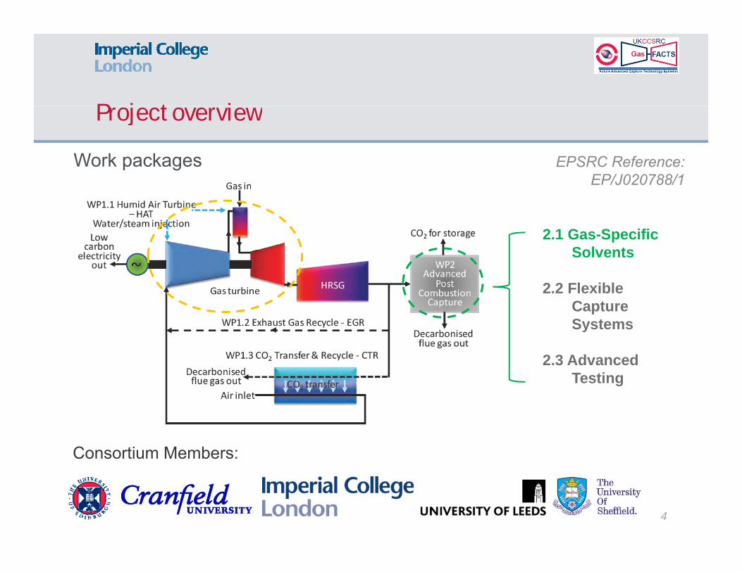
Work packages EPSRC Reference:EP/J020788/1
2.1 Gas-Specific Solvents
EP/J020788/1
Solvents
2.2 Flexible Capture SystemsSystems
2.3 Advanced Testing
Consortium Members:
4
Solvents selectionSolvents selection
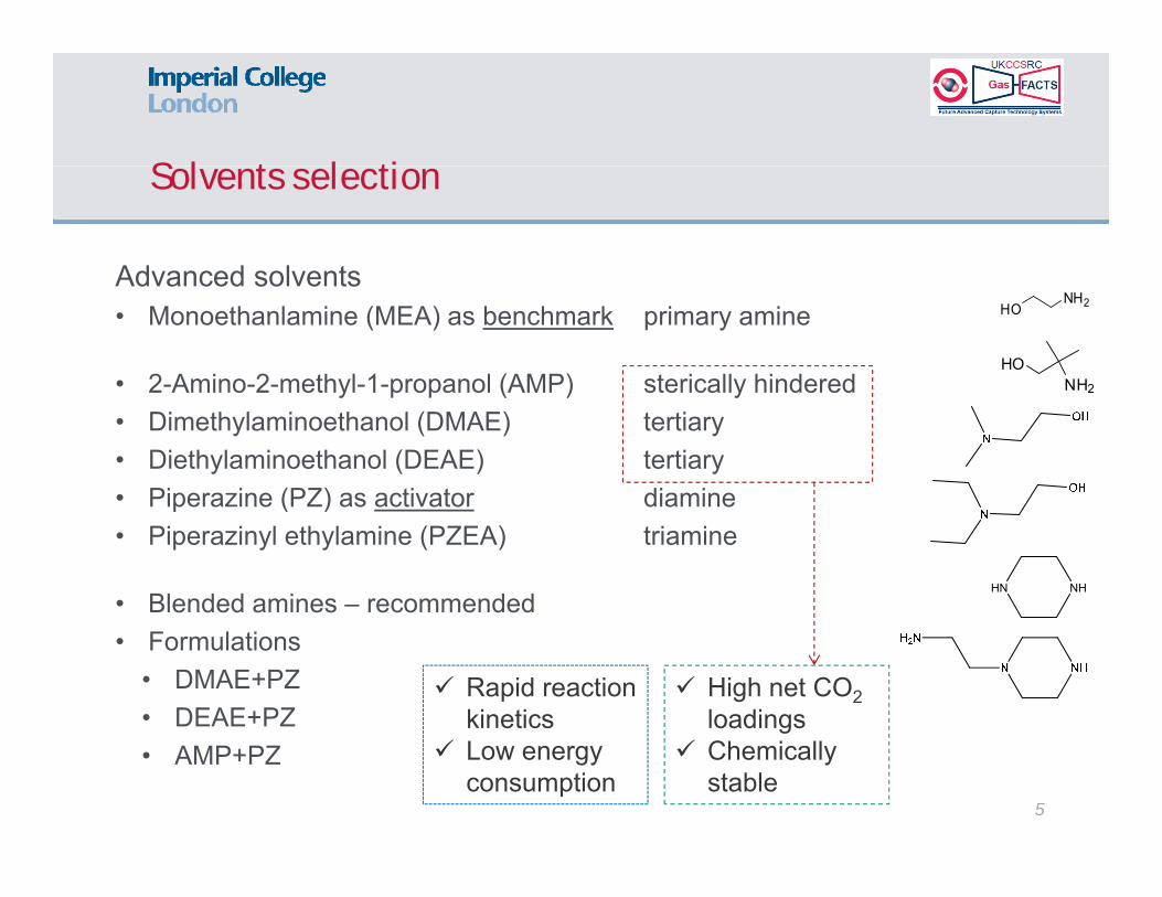
Advanced solventsAdvanced solvents• Monoethanlamine (MEA) as benchmark primary amine
• 2-Amino-2-methyl-1-propanol (AMP) sterically hinderedHO
NH2
NH2HO
2 Amino 2 methyl 1 propanol (AMP) sterically hindered• Dimethylaminoethanol (DMAE) tertiary • Diethylaminoethanol (DEAE) tertiary • Piperazine (PZ) as activator diamine
2
Piperazine (PZ) as activator diamine• Piperazinyl ethylamine (PZEA) triamine
• Blended amines – recommended HN NH
• Formulations• DMAE+PZ• DEAE+PZ
High net CO2loadings
Rapid reaction kinetics
5
• AMP+PZg
Chemically stable
Low energy consumption
Solvents selectionSolvents selection
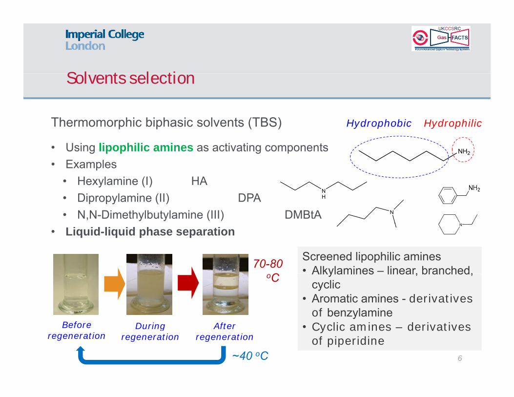
Thermomorphic biphasic solvents (TBS) Hydrophobic HydrophilicThermomorphic biphasic solvents (TBS)
• Using lipophilic amines as activating components • Examples
NH2
Hydrophobic Hydrophilic
• Hexylamine (I) HA• Dipropylamine (II) DPA• N,N-Dimethylbutylamine (III) DMBtA
NH
N
N
• Liquid-liquid phase separation
70-80 C
Screened lipophilic amines• Alkylamines – linear, branched,
N
Before D i Aft
oC Alkylamines linear, branched, cyclic
• Aromatic amines - derivatives of benzylamineC li i d i ti
6
Before regeneration
During regeneration
After regeneration
• Cyclic amines – derivatives of piperidine
~40 oC
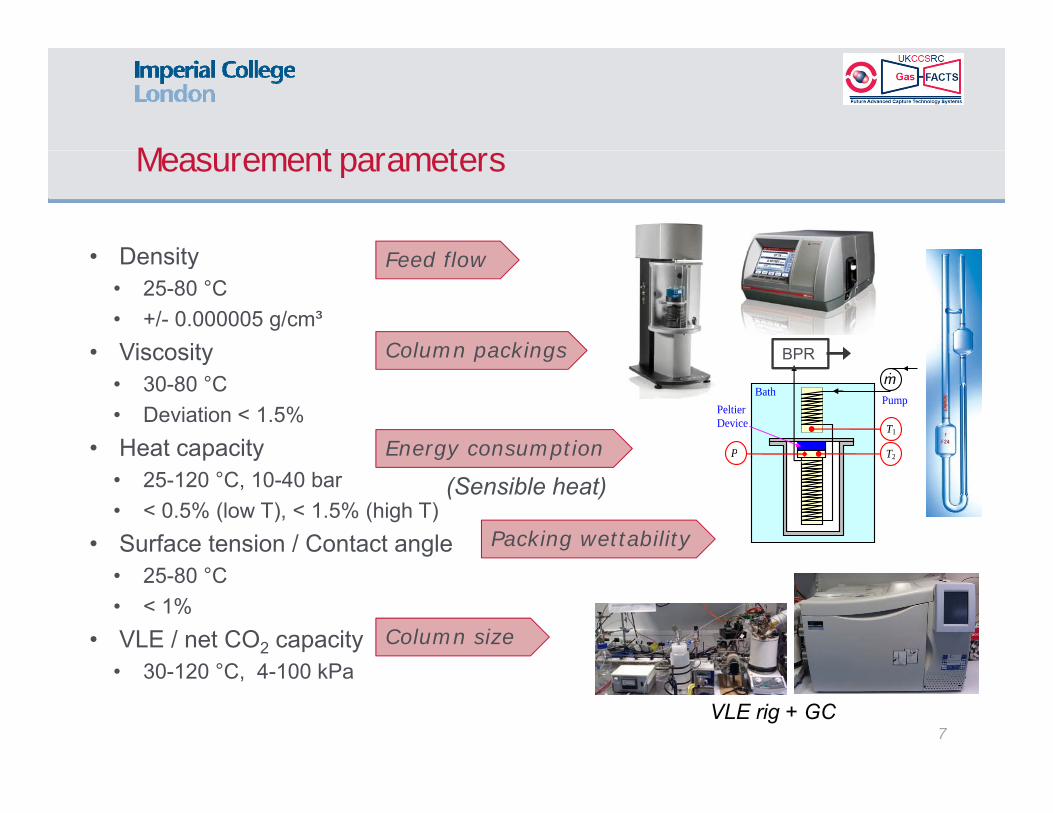
Measurement parametersMeasurement parameters
Density F d fl• Density• 25-80 °C• +/- 0.000005 g/cm³
• Viscosity BPR
Feed flow
Column packingsViscosity • 30-80 °C • Deviation < 1.5%
• Heat capacity T2
m
Peltier Device
Pump Bath
T1
P
BPRColumn packings
Energy consumptionp y• 25-120 °C, 10-40 bar• < 0.5% (low T), < 1.5% (high T)
• Surface tension / Contact angle
2gy p
Packing wettability
(Sensible heat)
• 25-80 °C • < 1%
• VLE / net CO2 capacity°C
Column size
• 30-120 °C, 4-100 kPa
7VLE rig + GC
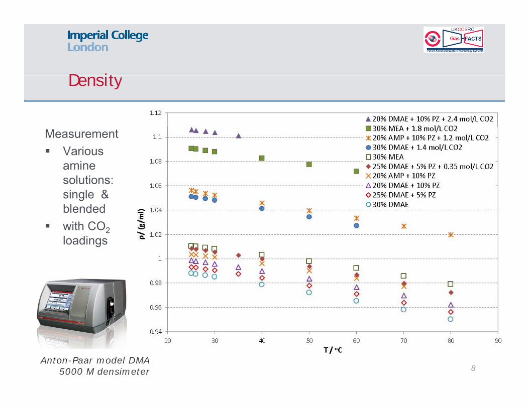
DensityDensity
Measurement Various
amine solutions:solutions: single & blended
with CO2with CO2loadings
8Anton-Paar model DMA
5000 M densimeter
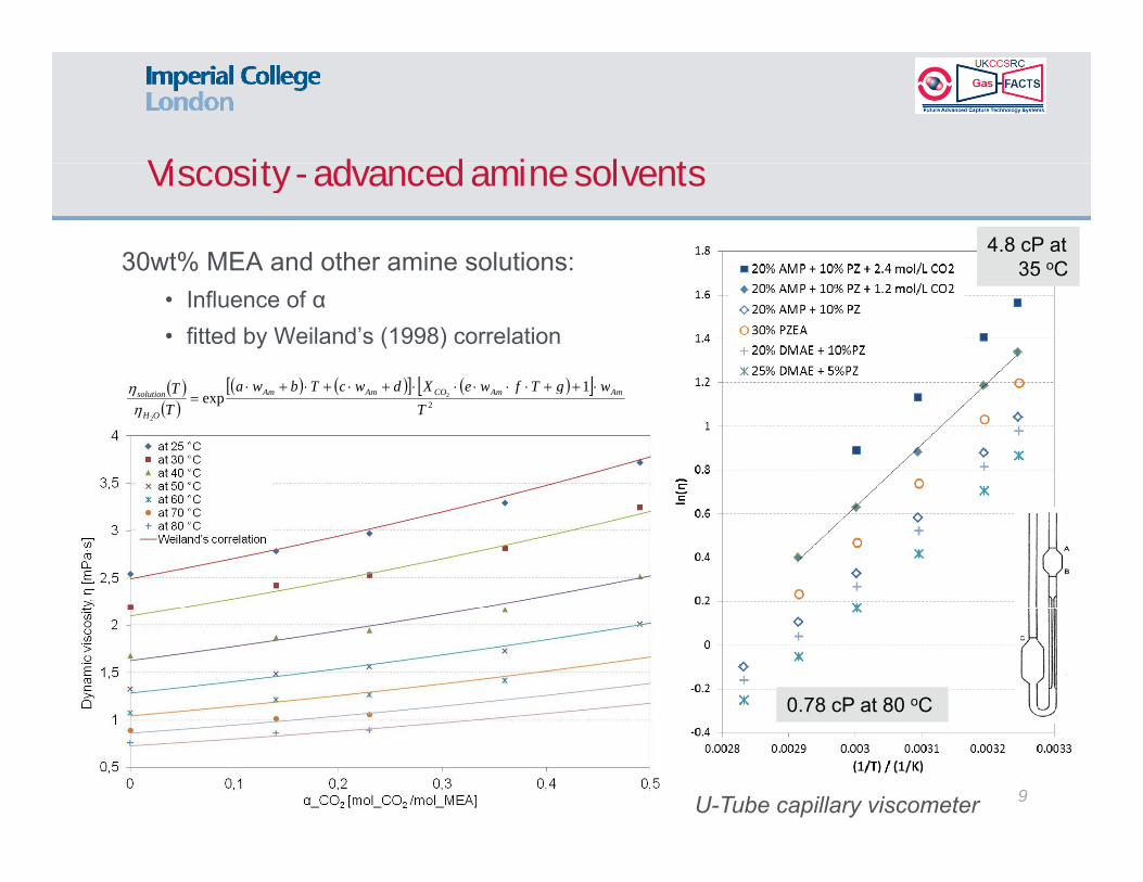
Viscosity advanced amine solvents Viscosity - advanced amine solvents
30wt% MEA and other amine solutions: 4.8 cP at
35 oC• Influence of α• fitted by Weiland’s (1998) correlation
1 wgTfweXdwcTbwaT
35 C
2
1exp 2
2T
wgTfweXdwcTbwaTT AmAmCOAmAm
OH
solution
0.78 cP at 80 oC
9U-Tube capillary viscometer
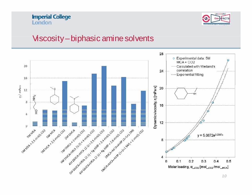
Viscosity biphasic amine solvents Viscosity – biphasic amine solvents N
H2
O
N
NH
NH
HO
10

Heat capacityHeat capacity
Flow calorimeter BPRFlow calorimeterm
Peltier Device
Pump Bath
T1 TmQC net
p
Influence: T ↑ Cp ↑α ↑ C ↓ (/g)
T2 P
α ↑ Cp ↓ (/g)α ↑ Cp ↑ (/ml)
11

Heat capacityHeat capacity
Solvents:
DMAE + PZAMP + PZPZEAetc.
12
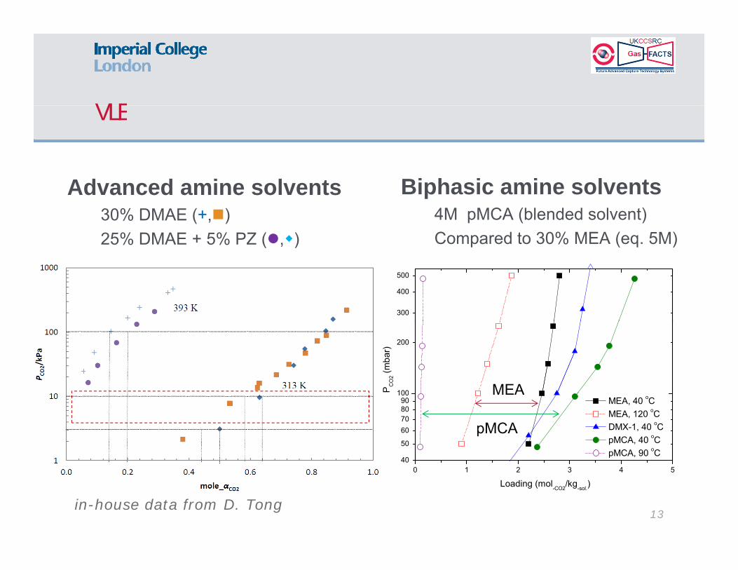
VLEVLE
Advanced amine solvents30% DMAE (+,)25% DMAE + 5% PZ (,)
Biphasic amine solvents4M pMCA (blended solvent)Compared to 30% MEA (eq. 5M)
300
400
500
100
200
P CO
2 (mba
r)
MEA
40
50
60708090
100 MEA, 40 oC MEA, 120 oC DMX-1, 40 oC pMCA, 40 oC pMCA, 90 oC
MEA
pMCA
13in-house data from D. Tong
0 1 2 3 4 5
Loading (mol-CO2/kg-sol.)

Net CO capacity Net CO2 capacity
Higher than benchmarks
40 120 C f40-120oC for alkanolamine
30 80oC for30-80oC for lipophilic amine
14

DegradtionDegradtion
Analysis
N
Analysis • Heat stable salts (HSS): titration• Volatile components: GC-MS
Main reactions N
• Demethylation / Methylation• Ketonisation & Oximation for MCA
6
HN
4
5
6 w/o Fe(II/III) w/ Fe(II/III)
2
3
HS
S /
%
TBS
15AMP Blend DMCA MEA MCA0
1

Surface tension & Contact angleSurface tension & Contact angle
+ CO loading+ CO2 loading • Increase ST• Increase CA
θ
Some plastic materials such as PE-HD: also wettable to lipophilic amines
16α ↑
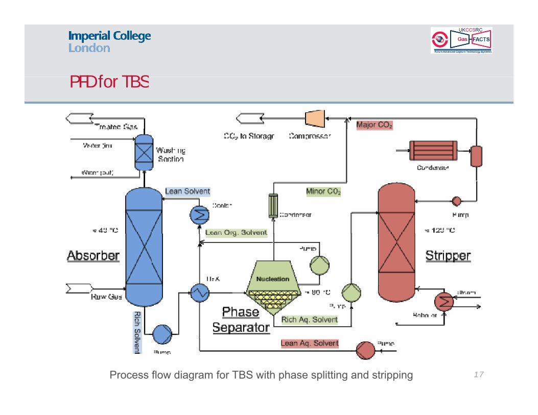
PFD for TBSPFD for TBS
17Process flow diagram for TBS with phase splitting and stripping
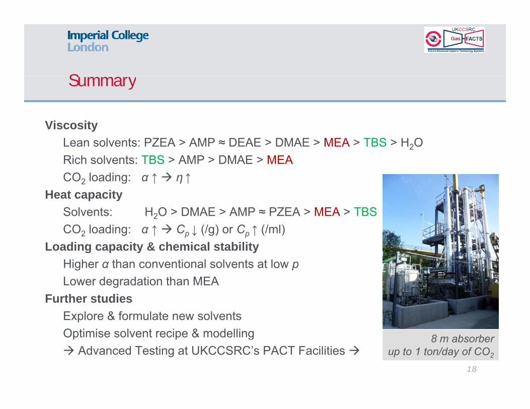
SummarySummary
ViscosityViscosityLean solvents: PZEA > AMP ≈ DEAE > DMAE > MEA > TBS > H2O Rich solvents: TBS > AMP > DMAE > MEACO2 loading: α ↑ η ↑CO2 loading: α ↑ η ↑
Heat capacity Solvents: H2O > DMAE > AMP ≈ PZEA > MEA > TBSCO loading: α ↑ C ↓ (/g) or C ↑ (/ml)CO2 loading: α ↑ Cp ↓ (/g) or Cp ↑ (/ml)
Loading capacity & chemical stability Higher α than conventional solvents at low p Lower degradation than MEALower degradation than MEA
Further studiesExplore & formulate new solventsOptimise solvent recipe & modellingOptimise solvent recipe & modelling Advanced Testing at UKCCSRC’s PACT Facilities
18
8 m absorberup to 1 ton/day of CO2
AcknowledgementAcknowledgement
The gas-specific solvents were studied in the Imperial College London and financial supported by the EPSRC
The biphasic solvent system was studied in the Technical University of Dortmund and supported by the Shell Globalby the EPSRC. supported by the Shell Global Solutions Int. B.V.
Advisors: Prof. Dr. David W. AgarProf. Dr. David W. Agar Dr. Frank Geuzebroek Ir. Mark Senden Dr. Robert Moene
Consortium Members:
Dr. Robert MoeneDr. Xiaohui Zhang
19

Thank you for your attention!
Selection and Development of Specific Solvents for CO2 Capture from
Natural Gas Power Systems:Natural Gas Power Systems:
monophasic & biphasic
Jiafei Zhang
Department of Chemical EngineeringImperial College London UK The Queen's Tower in the
20
Imperial College London, UKTel: +44 (0)20 7594 1185 E-mail: [email protected]
The Queen s Tower in the South Kensington Campus