Embed Size (px)
Citation preview
1
A Generalized Entropic Framework of Damage: Theory and Applications to
Corrosion-Fatigue
Mohammad Modarres Nicole Y. Kim Professor of Engineering
Presented at the Structural Mechanics (TIM 2015), Fall Church, VA
24 June 2015
Center for Risk and Reliability Department of Mechanical Engineering
University of Maryland, College Park, MD 20742, USA
2
Acknowledgments
The Team: 1. Ms. Anahita Imanian (PhD Candidate) 2. Dr. Mehdi Amiri (Postdoc up to 12/31/2014) 3. Dr. Victor Ontiveros (Former PhD candidate, high-cycle fatigue data) 4. Mr. M. Nuhi-Faridani (Experimental support/Lab technician) 5. Prof. C. Wang (Corrosion/electrolysis consultant) 6. Prof. Mohammad Modarres (PI)
Funding and oversight: Office of Naval Research Mr. William C. Nickerson Sea-Based Aviation Structures and Materials, Code 35 --Air Warfare & Weapons Department
3
Objectives
• Description of degradation mechanisms and resulting damages within the irreversible thermodynamics framework
• Improved understanding of the coupled mechanisms • Development of an entropic corrosion-fatigue damage model • Confirmatory testing of the corrosion-fatigue model • Investigation of applications to structural integrity and
reliability assessment • Search for applications to Prognosis and Health Management
(PHM) of structures
4
Motivation
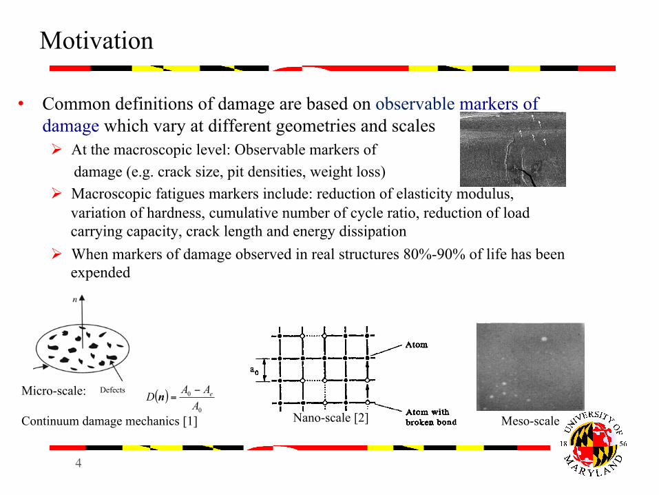
• Common definitions of damage are based on observable markers of damage which vary at different geometries and scales Ø At the macroscopic level: Observable markers of damage (e.g. crack size, pit densities, weight loss) Ø Macroscopic fatigues markers include: reduction of elasticity modulus,
variation of hardness, cumulative number of cycle ratio, reduction of load carrying capacity, crack length and energy dissipation
Ø When markers of damage observed in real structures 80%-90% of life has been expended
[1] J. Lemaitre, “A Course on Damage Mechanics”, Springer, France, 1996. [2] C. Woo & D. Li, “A Universal Physically Consistent Definition of Material Damage”, Int. J. Solids Structure, V30, 1993
Micro-scale: Continuum damage mechanics [1]
( )0
0
AAAD e−
=n
Nano-scale [2] Meso-scale
Defects
A0
5
Entropy and Damage
• Entropy provides a unified and broad measure of damage in terms of energy dissipations of multiple irreversible degradation processes
• Entropy enables us to model multiple competing degradation processes contributing to damage
• Entropy is independent of the path to failure for a system ending at similar total entropy at the time of failure
• Entropy accounts for synergistic effects arising from interactions between multiple degradation processes
• Entropy applies to all scales
6
Damage and Entropy
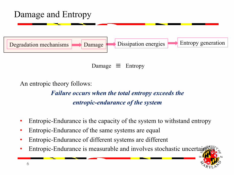
Damage ≡ Entropy An entropic theory follows:
Failure occurs when the total entropy exceeds the entropic-endurance of the system
• Entropic-Endurance is the capacity of the system to withstand entropy • Entropic-Endurance of the same systems are equal • Entropic-Endurance of different systems are different • Entropic-Endurance is measurable and involves stochastic uncertainties
Dissipation energies Damage Entropy generation Degradation mechanisms
7
Total Entropy
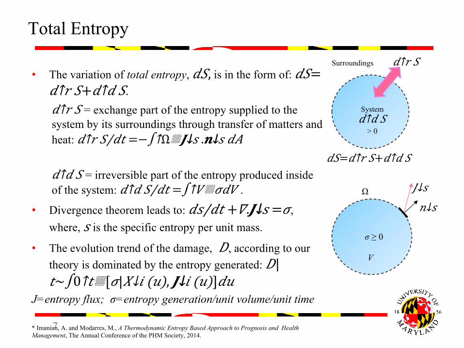
• The variation of total entropy, 𝑑𝑆, is in the form of: 𝑑𝑆= 𝑑↑𝑟 𝑆+ 𝑑↑𝑑 𝑆. 𝑑↑𝑟 𝑆 = exchange part of the entropy supplied to the system by its surroundings through transfer of matters and heat: 𝑑↑𝑟 𝑆/𝑑𝑡 =−∫↑Ω▒𝑱↓𝑠 . 𝒏↓𝑠 𝑑𝐴 𝑑↑𝑑 𝑆 = irreversible part of the entropy produced inside of the system: 𝑑↑𝑑 𝑆/𝑑𝑡 =∫↑𝑉▒𝜎𝑑𝑉 .
• Divergence theorem leads to: 𝑑𝑠/𝑑𝑡 +𝛻.𝑱↓𝑠 =𝜎, where, 𝑠 is the specific entropy per unit mass.
• The evolution trend of the damage, 𝐷, according to our theory is dominated by the entropy generated: 𝐷|𝑡~∫0↑𝑡▒[𝜎| 𝑋↓𝑖 (𝑢), 𝑱↓𝑖 (𝑢)]𝑑𝑢
J=entropy flux; σ=entropy generation/unit volume/unit time * Imanian, A. and Modarres, M., A Thermodynamic Entropy Based Approach to Prognosis and Health Management, The Annual Conference of the PHM Society, 2014.
𝐽↓𝑠 Ω
V
σ ≥ 0
System 𝑑↑𝑑 𝑆
> 0
Surroundings 𝑑↑𝑟 𝑆
𝑑𝑆= 𝑑↑𝑟 𝑆+ 𝑑↑𝑑 𝑆
𝑛↓𝑠
8
Total Entropy Generated (Cont.)
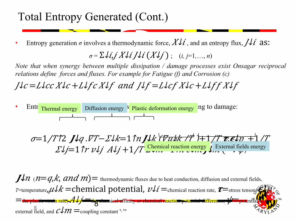
• Entropy generation σ involves a thermodynamic force, 𝑋↓𝑖 , and an entropy flux, 𝐽↓𝑖 as: σ = Σ↓𝑖,𝑗 𝑋↓𝑖 𝐽↓𝑖 ( 𝑋↓𝑗 ) ; (i, j=1,…, n)
Note that when synergy between multiple dissipation / damage processes exist Onsagar reciprocal relations define forces and fluxes. For example for Fatigue (f) and Corrosion (c)
𝐽↓𝑐 = 𝐿↓𝑐𝑐 𝑋↓𝑐 + 𝐿↓𝑓𝑐 𝑋↓𝑓 𝑎𝑛𝑑 𝐽↓𝑓 = 𝐿↓𝑐𝑓 𝑋↓𝑐 + 𝐿↓𝑓𝑓 𝑋↓𝑓
• Entropy generation of important dissipation phenomena leading to damage:
𝜎= 1/𝑇↑2 𝑱↓𝑞 .𝛻𝑇− 𝛴↓𝑘=1↑𝑛 𝑱↓𝑘 (𝛻𝜇↓𝑘 /𝑇 )+ 1/𝑇 𝝉:𝝐↓𝑝 + 1/𝑇 𝛴↓𝑗=1↑𝑟 𝑣↓𝑗 𝐴↓𝑗 + 1/𝑇 𝛴↓𝑚=1↑ℎ 𝑐↓𝑚 𝑱↓𝑚 (−𝛻𝜓)
𝑱↓𝑛 (𝑛=𝑞,𝑘, 𝑎𝑛𝑑 𝑚)= thermodynamic fluxes due to heat conduction, diffusion and external fields,
T=temperature, 𝜇↓𝑘 =chemical potential, 𝑣↓𝑖 =chemical reaction rate, 𝝉=stress tensor, 𝝐↓𝑝 =the plastic strain rate, 𝐴↓𝑗 =the chemical affinity or chemical reaction potential difference, 𝜓=potential of the
external field, and 𝑐↓𝑚 =coupling constant *, ** * D. Kondepudi and I. Prigogine, “Modern Thermodynamics: From Heat Engines to Dissipative Structures, ” Wiley, England, 1998. ** J. Lemaitre and J. L. Chaboche, “Mechanics of Solid Materials, ” 3rd edition; Cambridge University Press: Cambridge, UK, 2000.
Thermal energy Diffusion energy Plastic deformation energy
Chemical reaction energy External fields energy
8
9
Examples of Force and Flux of Dissipative Processes
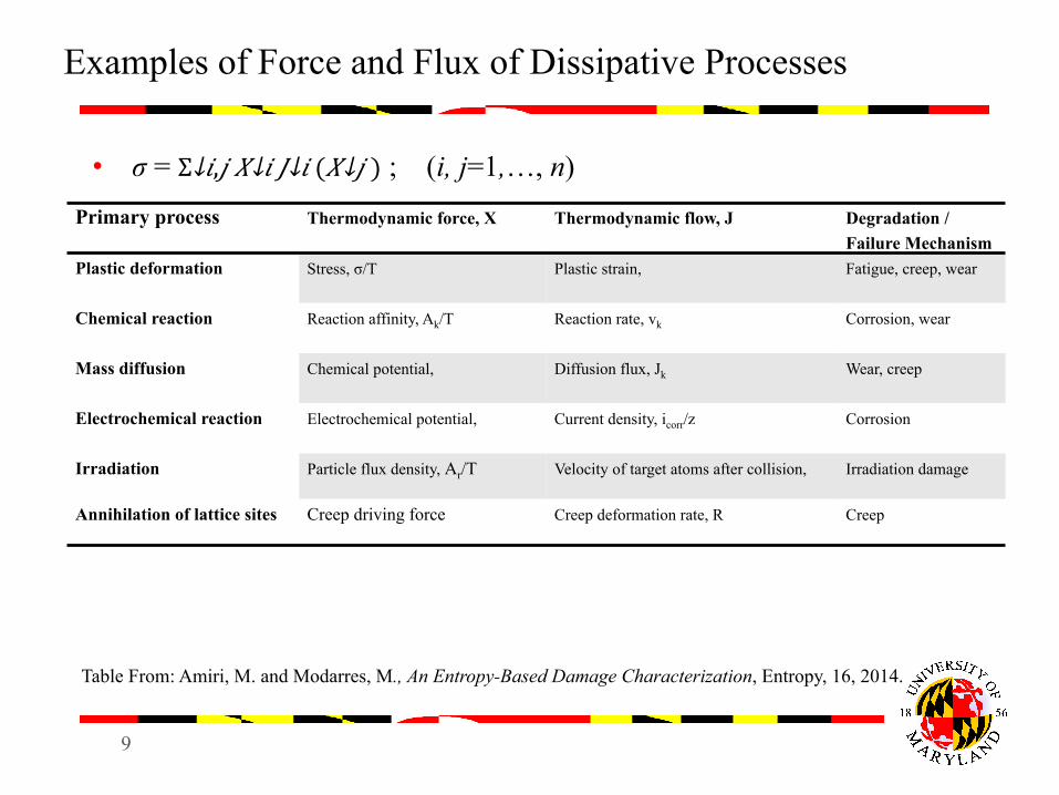
• σ = Σ↓𝑖,𝑗 𝑋↓𝑖 𝐽↓𝑖 ( 𝑋↓𝑗 ) ; (i, j=1,…, n)
Table From: Amiri, M. and Modarres, M., An Entropy-Based Damage Characterization, Entropy, 16, 2014.
Primary process Thermodynamic force, X Thermodynamic flow, J Degradation / Failure Mechanism
Plastic deformation
Stress, σ/T Plastic strain, Fatigue, creep, wear
Chemical reaction
Reaction affinity, Ak/T Reaction rate, vk Corrosion, wear
Mass diffusion Chemical potential,
Diffusion flux, Jk Wear, creep
Electrochemical reaction
Electrochemical potential, Current density, icorr/z Corrosion
Irradiation Particle flux density, Ar/T Velocity of target atoms after collision, Irradiation damage
Annihilation of lattice sites Creep driving force Creep deformation rate, R Creep
10
Entropic-Based Damage from Corrosion-Fatigue (CF)
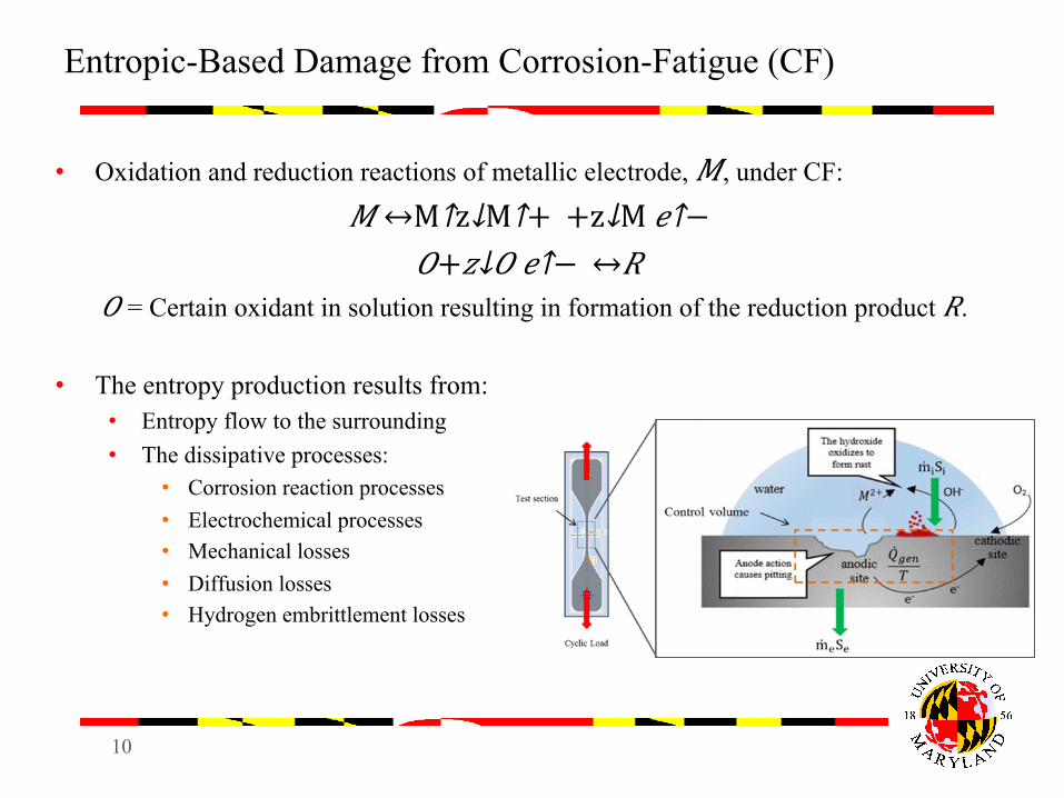
• Oxidation and reduction reactions of metallic electrode, 𝑀, under CF:
𝑀 ↔M↑z↓M↑+ + z↓M 𝑒↑− 𝑂+ 𝑧↓𝑂 𝑒↑− ↔𝑅
𝑂 = Certain oxidant in solution resulting in formation of the reduction product 𝑅.
• The entropy production results from: • Entropy flow to the surrounding • The dissipative processes:
• Corrosion reaction processes • Electrochemical processes • Mechanical losses • Diffusion losses • Hydrogen embrittlement losses
11
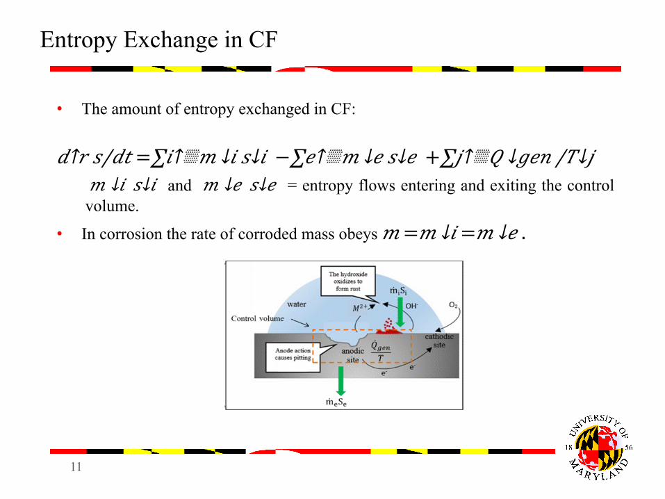
Entropy Exchange in CF
• The amount of entropy exchanged in CF:
𝑑↑𝑟 𝑠/𝑑𝑡 =∑𝑖↑▒𝑚 ↓𝑖 𝑠↓𝑖 −∑𝑒↑▒𝑚 ↓𝑒 𝑠↓𝑒 +∑𝑗↑▒𝑄 ↓𝑔𝑒𝑛 /𝑇↓𝑗 𝑚 ↓𝑖 𝑠↓𝑖 and 𝑚 ↓𝑒 𝑠↓𝑒 = entropy flows entering and exiting the control volume.
• In corrosion the rate of corroded mass obeys 𝑚 = 𝑚 ↓𝑖 = 𝑚 ↓𝑒 .
12
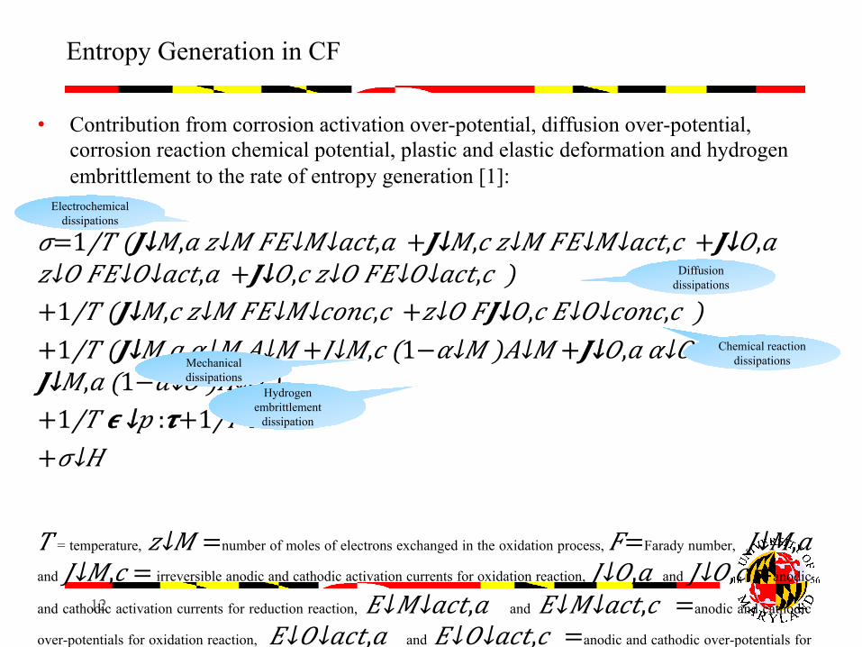
• Contribution from corrosion activation over-potential, diffusion over-potential, corrosion reaction chemical potential, plastic and elastic deformation and hydrogen embrittlement to the rate of entropy generation [1]:
𝜎= 1/𝑇 (𝑱↓𝑀,𝑎 𝑧↓𝑀 𝐹𝐸↓𝑀↓𝑎𝑐𝑡,𝑎 + 𝑱↓𝑀,𝑐 𝑧↓𝑀 𝐹𝐸↓𝑀↓𝑎𝑐𝑡,𝑐 + 𝑱↓𝑂,𝑎 𝑧↓𝑂 𝐹𝐸↓𝑂↓𝑎𝑐𝑡,𝑎 + 𝑱↓𝑂,𝑐 𝑧↓𝑂 𝐹𝐸↓𝑂↓𝑎𝑐𝑡,𝑐 )
+ 1/𝑇 (𝑱↓𝑀,𝑐 𝑧↓𝑀 𝐹𝐸↓𝑀↓𝑐𝑜𝑛𝑐,𝑐 + 𝑧↓𝑂 𝐹𝑱↓𝑂,𝑐 𝐸↓𝑂↓𝑐𝑜𝑛𝑐,𝑐 )
+ 1/𝑇 (𝑱↓𝑀,𝑎 𝛼↓𝑀 𝐴↓𝑀 + 𝐽↓𝑀,𝑐 (1− 𝛼↓𝑀 )𝐴↓𝑀 + 𝑱↓𝑂,𝑎 𝛼↓𝑂 𝐴↓𝑂 + 𝑱↓𝑀,𝑎 (1− 𝛼↓𝑂 )𝐴↓𝑂 )
+ 1/𝑇 𝝐 ↓𝑝 :𝝉+ 1/𝑇 𝑌𝑫 + 𝜎↓𝐻
𝑇 = temperature, 𝑧↓𝑀 =number of moles of electrons exchanged in the oxidation process, 𝐹=Farady number, 𝐽↓𝑀,𝑎 and 𝐽↓𝑀,𝑐 = irreversible anodic and cathodic activation currents for oxidation reaction, 𝐽↓𝑂,𝑎 and 𝐽↓𝑂,𝑐 =anodic
and cathodic activation currents for reduction reaction, 𝐸↓𝑀↓𝑎𝑐𝑡,𝑎 and 𝐸↓𝑀↓𝑎𝑐𝑡,𝑐 =anodic and cathodic
over-potentials for oxidation reaction, 𝐸↓𝑂↓𝑎𝑐𝑡,𝑎 and 𝐸↓𝑂↓𝑎𝑐𝑡,𝑐 =anodic and cathodic over-potentials for
reduction reaction, 𝐸↓𝑀↓𝑐𝑜𝑛𝑐,𝑐 and 𝐸↓𝑂↓𝑐𝑜𝑛𝑐,𝑐 =concentration over-potentials for the cathodic oxidation
and cathodic reduction reactions, 𝛼↓𝑀 and 𝛼↓𝑂 =charge transport coefficient for the oxidation and reduction reactions, 𝐴↓𝑀 and 𝐴↓𝑂 = chemical affinity for the oxidation and reductions, 𝜖 ↓𝑝 =plastic deformation rate, 𝜏 =plastic stress, 𝐷 =dimensionless damage flux, 𝑌 the elastic energy, and 𝜎↓𝐻 =entropy generation due to hydrogen embrittlement. [1] Imanian, A. and Modarres. M, “A Thermodynamic Entropy Based Approach for Prognosis and Health Management with Application to Corrosion-Fatigue,” 2015 IEEE International Conference on Prognostics and Health Management, 22-25 June, 2015, Austin, USA.
Entropy Generation in CF
Electrochemical dissipations
Diffusion dissipations
Chemical reaction dissipations Mechanical
dissipations Hydrogen
embrittlement dissipation
13
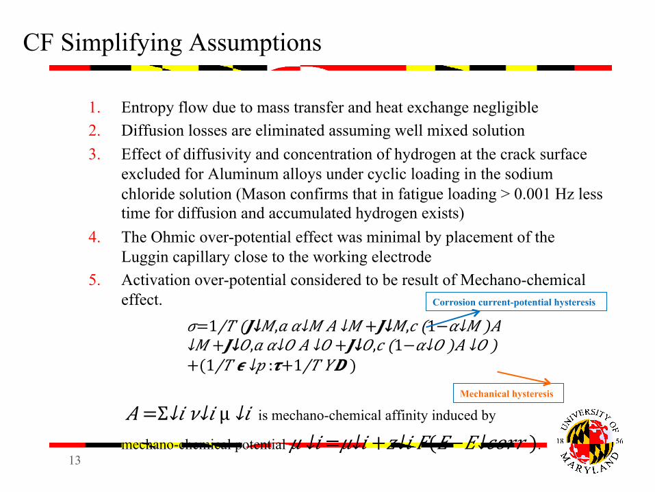
CF Simplifying Assumptions
1. Entropy flow due to mass transfer and heat exchange negligible 2. Diffusion losses are eliminated assuming well mixed solution 3. Effect of diffusivity and concentration of hydrogen at the crack surface
excluded for Aluminum alloys under cyclic loading in the sodium chloride solution (Mason confirms that in fatigue loading > 0.001 Hz less time for diffusion and accumulated hydrogen exists)
4. The Ohmic over-potential effect was minimal by placement of the Luggin capillary close to the working electrode
5. Activation over-potential considered to be result of Mechano-chemical effect.
𝐴 = Σ↓𝑖 𝜈↓𝑖 µ ↓𝑖 is mechano-chemical affinity induced by
mechano-chemical potential 𝜇 ↓𝑖 = 𝜇↓𝑖 + 𝑧↓𝑖 𝐹(𝐸− 𝐸↓𝑐𝑜𝑟𝑟 ).
𝜎= 1/𝑇 (𝑱↓𝑀,𝑎 𝛼↓𝑀 𝐴 ↓𝑀 + 𝑱↓𝑀,𝑐 (1− 𝛼↓𝑀 )𝐴 ↓𝑀 + 𝑱↓𝑂,𝑎 𝛼↓𝑂 𝐴 ↓𝑂 + 𝑱↓𝑂,𝑐 (1− 𝛼↓𝑂 )𝐴 ↓𝑂 )+( 1/𝑇 𝝐 ↓𝑝 :𝝉+ 1/𝑇 𝑌𝑫 )
Corrosion current-potential hysteresis
Mechanical hysteresis
14
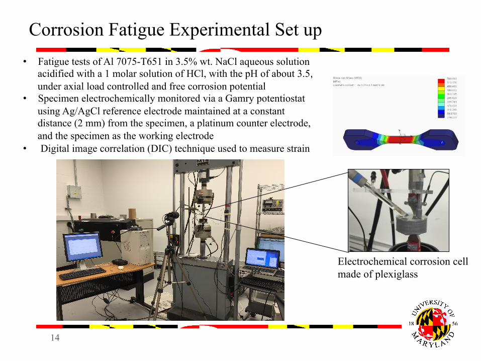
Corrosion Fatigue Experimental Set up • Fatigue tests of Al 7075-T651 in 3.5% wt. NaCl aqueous solution
acidified with a 1 molar solution of HCl, with the pH of about 3.5, under axial load controlled and free corrosion potential
• Specimen electrochemically monitored via a Gamry potentiostat using Ag/AgCl reference electrode maintained at a constant distance (2 mm) from the specimen, a platinum counter electrode, and the specimen as the working electrode
• Digital image correlation (DIC) technique used to measure strain
Electrochemical corrosion cell made of plexiglass
15
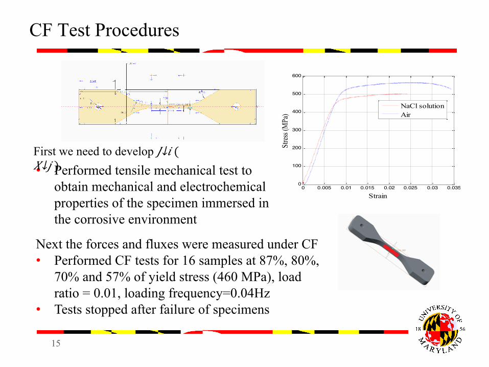
CF Test Procedures
• Performed tensile mechanical test to obtain mechanical and electrochemical properties of the specimen immersed in the corrosive environment
0 0.005 0.01 0.015 0.02 0.025 0.03 0.0350
100
200
300
400
500
600
Strain
Stres
s (M
Pa)
NaCl solutionAir
Next the forces and fluxes were measured under CF • Performed CF tests for 16 samples at 87%, 80%,
70% and 57% of yield stress (460 MPa), load ratio = 0.01, loading frequency=0.04Hz
• Tests stopped after failure of specimens
First we need to develop 𝐽↓𝑖 ( 𝑋↓𝑗 )
16
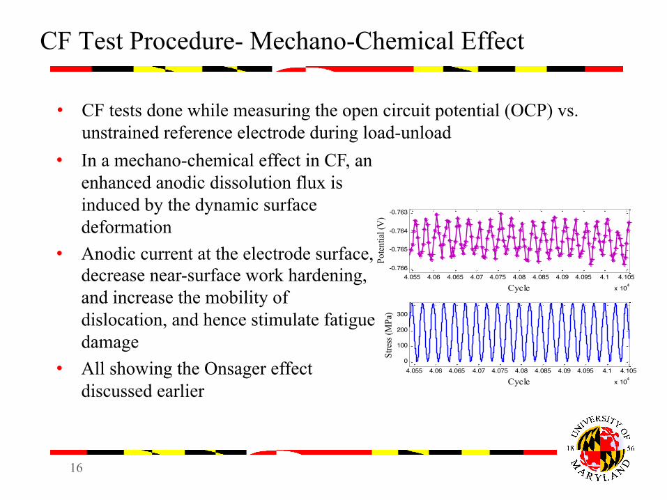
CF Test Procedure- Mechano-Chemical Effect
• CF tests done while measuring the open circuit potential (OCP) vs. unstrained reference electrode during load-unload
4.055 4.06 4.065 4.07 4.075 4.08 4.085 4.09 4.095 4.1 4.105
x 104
-0.766
-0.765
-0.764
-0.763
Cycle
Poten
tial (
V)
4.055 4.06 4.065 4.07 4.075 4.08 4.085 4.09 4.095 4.1 4.105
x 104
0
100
200
300
CycleSt
ress
(MPa
)
• In a mechano-chemical effect in CF, an enhanced anodic dissolution flux is induced by the dynamic surface deformation
• Anodic current at the electrode surface, decrease near-surface work hardening, and increase the mobility of dislocation, and hence stimulate fatigue damage
• All showing the Onsager effect discussed earlier
17
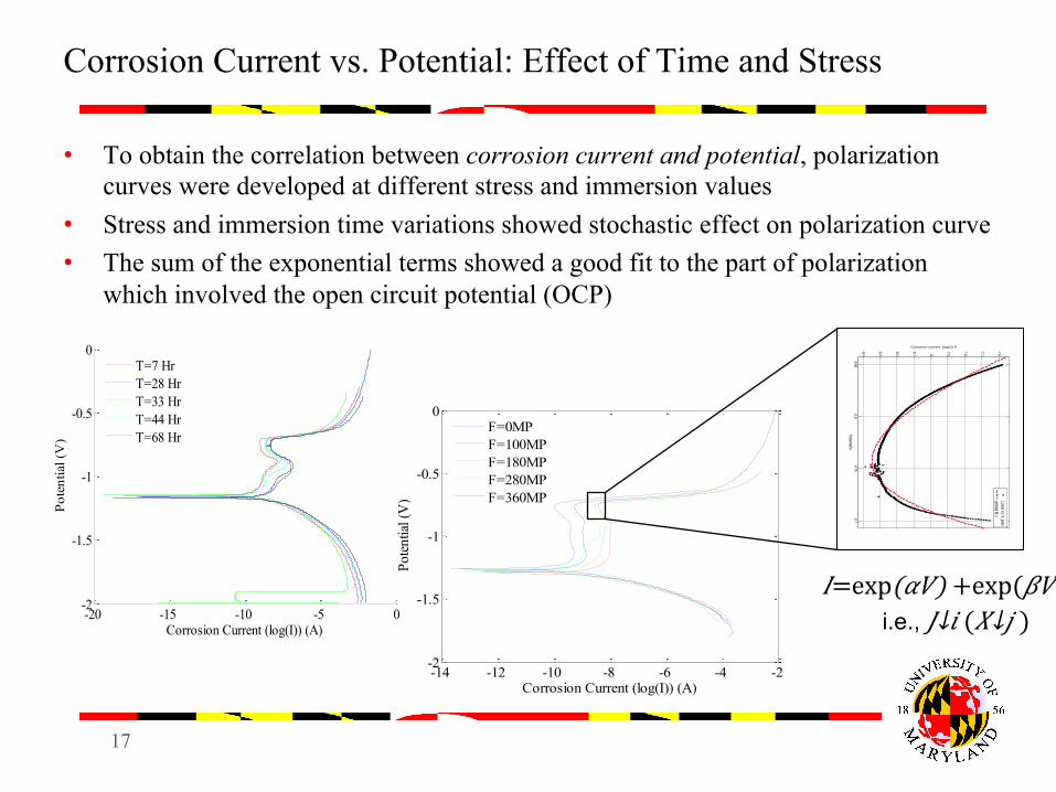
Corrosion Current vs. Potential: Effect of Time and Stress
• To obtain the correlation between corrosion current and potential, polarization curves were developed at different stress and immersion values
• Stress and immersion time variations showed stochastic effect on polarization curve • The sum of the exponential terms showed a good fit to the part of polarization
which involved the open circuit potential (OCP)
-14 -12 -10 -8 -6 -4 -2-2
-1.5
-1
-0.5
0Po
tentia
l (V
)
Corrosion Current (log(I)) (A)
F=0MPF=100MPF=180MPF=280MPF=360MP
-20 -15 -10 -5 0-2
-1.5
-1
-0.5
0
Corrosion Current (log(I)) (A)
Pote
ntia
l (V
)
T=7 HrT=28 HrT=33 HrT=44 HrT=68 Hr
-0.85-0.8
-0.75-0.7
-8.4
-8.3
-8.2
-8.1 -8
-7.9
-7.8
-7.7
-7.6
Potential(V)
Corrosion current (log(I)) A
I_pass vs. V_passuntitled fit 1
𝐼= exp(𝛼𝑉) +exp(𝛽𝑉)
i.e., 𝐽↓𝑖 ( 𝑋↓𝑗 )
18
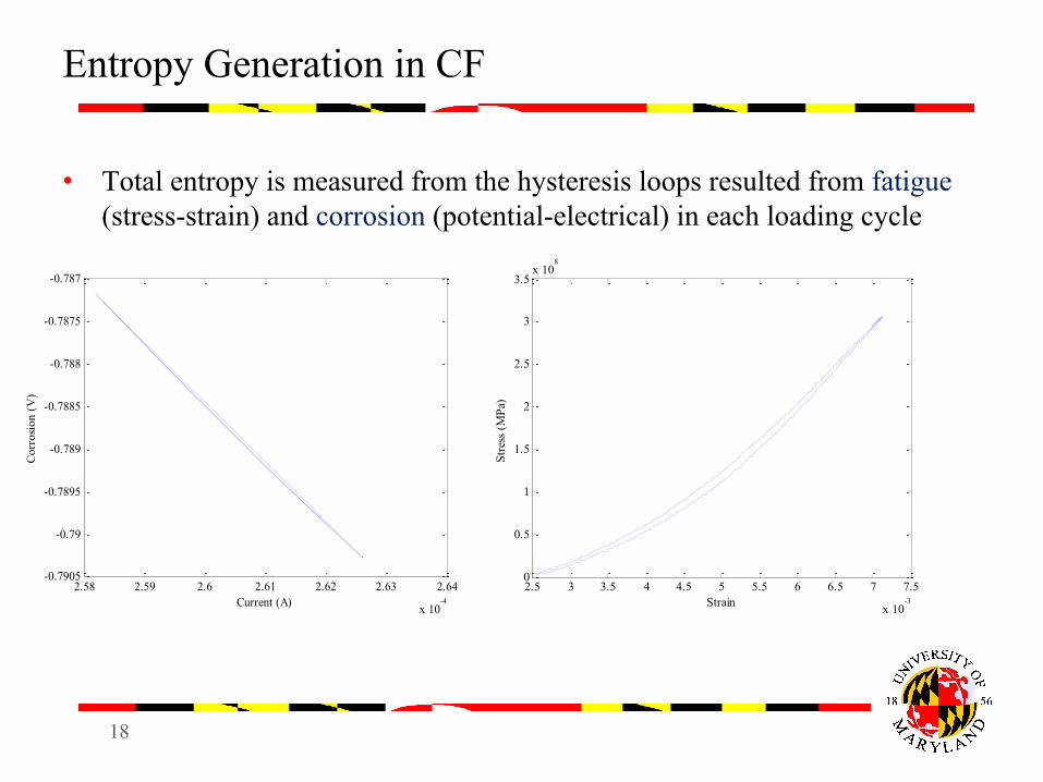
Entropy Generation in CF
• Total entropy is measured from the hysteresis loops resulted from fatigue (stress-strain) and corrosion (potential-electrical) in each loading cycle
2.5 3 3.5 4 4.5 5 5.5 6 6.5 7 7.5
x 10-3
0
0.5
1
1.5
2
2.5
3
3.5x 10
8
Stre
ss (M
Pa)
Strain2.58 2.59 2.6 2.61 2.62 2.63 2.64
x 10-4
-0.7905
-0.79
-0.7895
-0.789
-0.7885
-0.788
-0.7875
-0.787
Cor
rosi
on (
V)
Current (A)
19
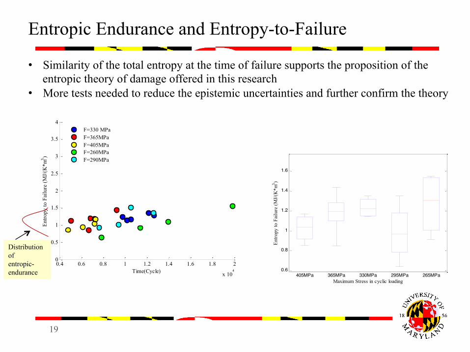
Entropic Endurance and Entropy-to-Failure
0.6
0.8
1
1.2
1.4
1.6
405MPa 365MPa 330MPa 295MPa 265MPaMaximum Stress in cyclic loading
Entro
py to
Fai
lure
(MJ/(
K*m
3 )
0.4 0.6 0.8 1 1.2 1.4 1.6 1.8 2
x 104
0
0.5
1
1.5
2
2.5
3
3.5
4
Entro
py to
Fai
lure
(MJ/(
K*m
3 )
Time(Cycle)
F=330 MPaF=365MPaF=405MPaF=260MPaF=290MPa
• Similarity of the total entropy at the time of failure supports the proposition of the entropic theory of damage offered in this research
• More tests needed to reduce the epistemic uncertainties and further confirm the theory
Distribution of entropic- endurance
20
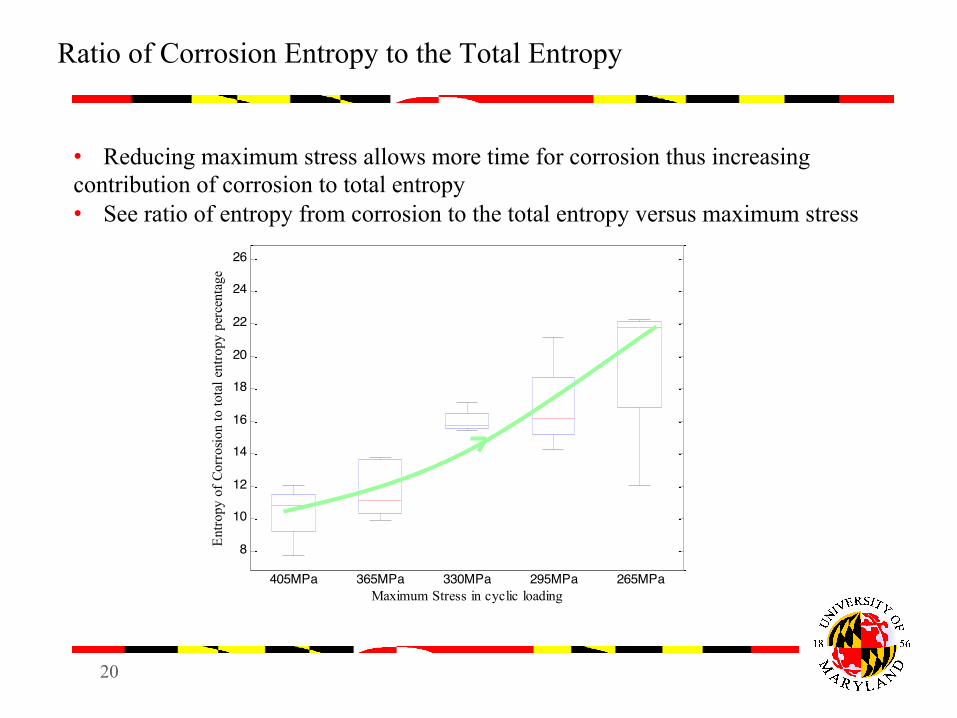
Ratio of Corrosion Entropy to the Total Entropy
• Reducing maximum stress allows more time for corrosion thus increasing contribution of corrosion to total entropy • See ratio of entropy from corrosion to the total entropy versus maximum stress
8
10
12
14
16
18
20
22
24
26
405MPa 365MPa 330MPa 295MPa 265MPaMaximum Stress in cyclic loading
Entro
py o
f Cor
rosio
n to
tota
l ent
ropy
per
cent
age
21
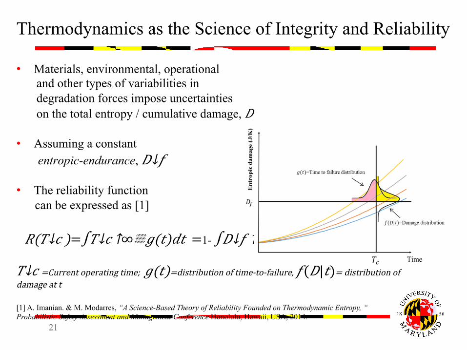
Thermodynamics as the Science of Integrity and Reliability
• Materials, environmental, operational and other types of variabilities in degradation forces impose uncertainties on the total entropy / cumulative damage, 𝐷
• Assuming a constant entropic-endurance, 𝐷↓𝑓 • The reliability function can be expressed as [1]
𝑅(𝑇↓𝑐 )=∫𝑇↓𝑐 ↑∞▒𝑔(𝑡)𝑑𝑡 =1- ∫𝐷↓𝑓 ↑∞▒𝑓(𝐷|𝑡)𝑑𝐷
𝑇↓𝑐 =Current operating time; 𝑔(𝑡)=distribution of time-to-failure, 𝑓(𝐷|𝑡)= distribution of damage at t [1] A. Imanian. & M. Modarres, “A Science-Based Theory of Reliability Founded on Thermodynamic Entropy, “ Probabilistic Safety Assessment and Management Conference Honolulu, Hawaii, USA, 2014.
22
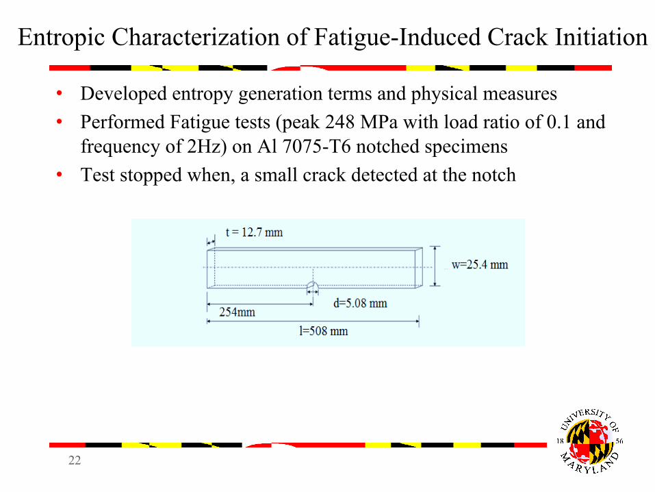
Entropic Characterization of Fatigue-Induced Crack Initiation
• Developed entropy generation terms and physical measures • Performed Fatigue tests (peak 248 MPa with load ratio of 0.1 and
frequency of 2Hz) on Al 7075-T6 notched specimens • Test stopped when, a small crack detected at the notch
23
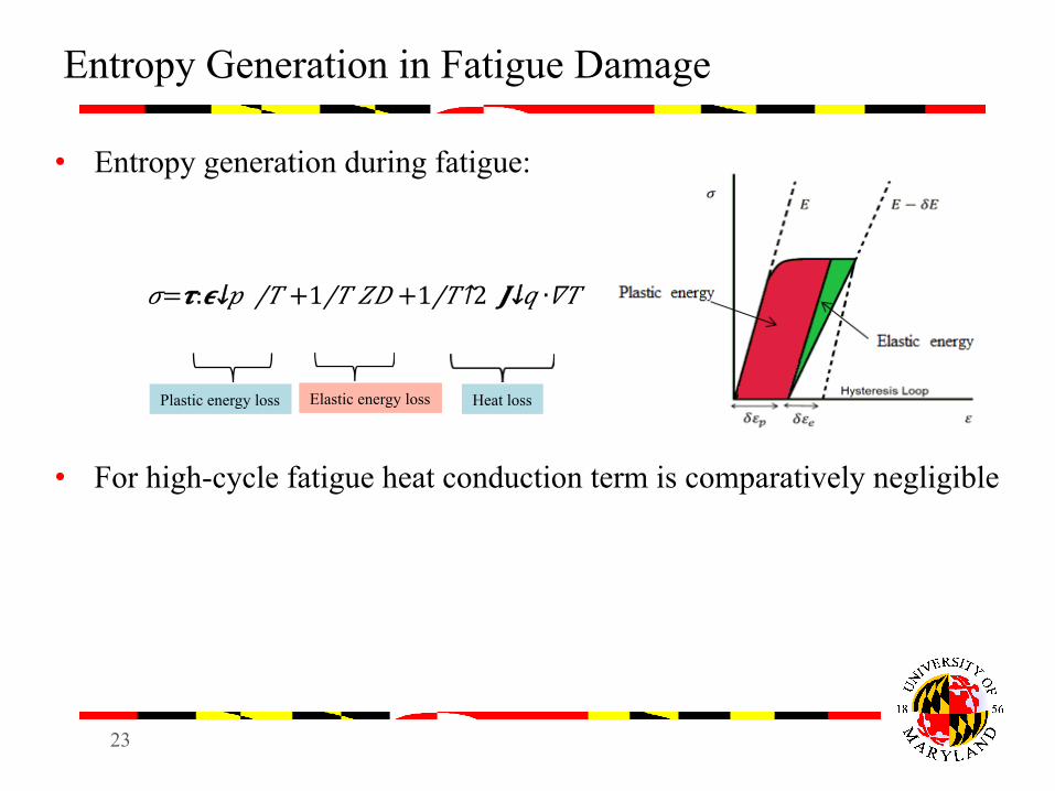
Entropy Generation in Fatigue Damage
• Entropy generation during fatigue:
𝜎= 𝝉:𝝐↓𝑝 /𝑇 + 1/𝑇 𝑍𝐷 + 1/𝑇↑2 𝑱↓𝑞 ∙𝛻𝑇 • For high-cycle fatigue heat conduction term is comparatively negligible
Plastic energy loss Elastic energy loss Heat loss
24
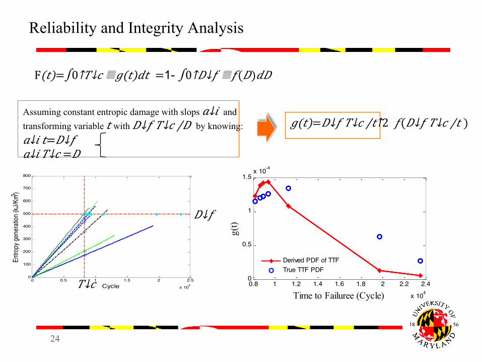
Reliability and Integrity Analysis
0 0.5 1 1.5 2 2.5
x 104
0
100
200
300
400
500
600
700
800
Cycle
Entro
py ge
nera
tion (
kJ/K
m3 )
F(𝑡)=∫0↑𝑇↓𝑐 ▒𝑔(𝑡)𝑑𝑡 =1- ∫0↑𝐷↓𝑓 ▒𝑓(𝐷)𝑑𝐷
Assuming constant entropic damage with slops 𝑎↓𝑖 and transforming variable 𝑡 with 𝐷↓𝑓 𝑇↓𝑐 /𝐷 by knowing: 𝑎↓𝑖 𝑡= 𝐷↓𝑓 𝑎↓𝑖 𝑇↓𝑐 =𝐷
𝑔(𝑡)= 𝐷↓𝑓 𝑇↓𝑐 /𝑡↑2 𝑓( 𝐷↓𝑓 𝑇↓𝑐 /𝑡 )
𝐷↓𝑓
𝑇↓𝑐 0.8 1 1.2 1.4 1.6 1.8 2 2.2 2.4
x 104
0
0.5
1
1.5x 10⁻⁴
Time to Failuree (Cycle)
g(t)
Derived PDF of TTFTrue TTF PDF
25
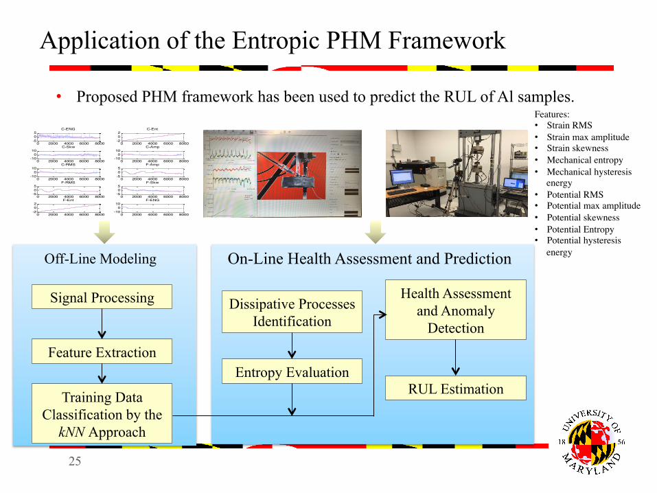
Application of the Entropic PHM Framework
Signal Processing
Feature Extraction
Training Data Classification by the
kNN Approach
Dissipative Processes Identification
Entropy Evaluation
Health Assessment and Anomaly
Detection
RUL Estimation
Off-Line Modeling On-Line Health Assessment and Prediction
0 2000 4000 6000 8000-505
C-ENG
0 2000 4000 6000 8000-202
C-Ent
0 2000 4000 6000 8000-10010
C-Skw
0 2000 4000 6000 8000-10010
C-Amp
0 2000 4000 6000 8000-10010
C-RMS
0 2000 4000 6000 8000-505
F-Amp
0 2000 4000 6000 8000-505
F-RMS
0 2000 4000 6000 8000-505
F-Skw
0 2000 4000 6000 8000-202
F-Ent
0 2000 4000 6000 8000-10010
F-ENG
• Proposed PHM framework has been used to predict the RUL of Al samples. Features:• Strain RMS• Strain max amplitude • Strain skewness • Mechanical entropy• Mechanical hysteresis
energy • Potential RMS• Potential max amplitude • Potential skewness • Potential Entropy• Potential hysteresis
energy
26
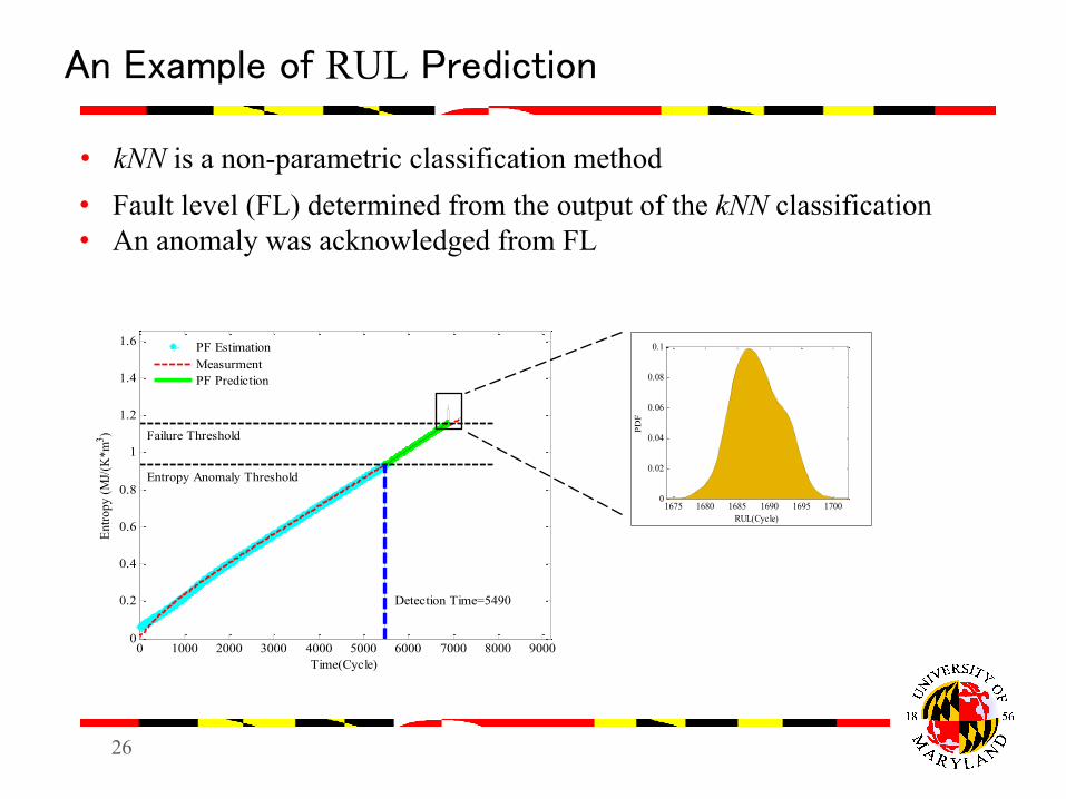
An Example of RUL Prediction
0 1000 2000 3000 4000 5000 6000 7000 8000 90000
0.2
0.4
0.6
0.8
1
1.2
1.4
1.6
Entro
py (M
J/(K
*m3 )
Time(Cycle)
Failure Threshold
Entropy Anomaly Threshold
Detection Time=5490
PF EstimationMeasurmentPF Prediction
1675 1680 1685 1690 1695 17000
0.02
0.04
0.06
0.08
0.1
RUL(Cycle)
• kNN is a non-parametric classification method • Fault level (FL) determined from the output of the kNN classification • An anomaly was acknowledged from FL
27
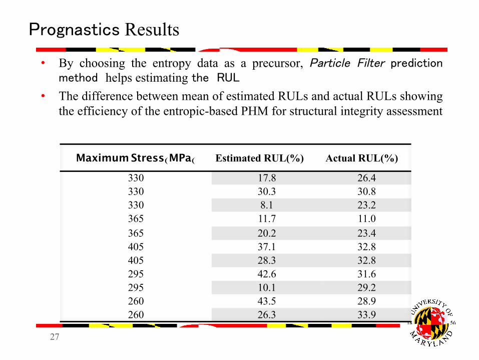
Prognastics Results
• By choosing the entropy data as a precursor, Particle Filter prediction method helps estimating the RUL
• The difference between mean of estimated RULs and actual RULs showing the efficiency of the entropic-based PHM for structural integrity assessment
Maximum Stress(MPa( Estimated RUL(%) Actual RUL(%)
330 17.8 26.4 330 30.3 30.8 330 8.1 23.2 365 11.7 11.0 365 20.2 23.4 405 37.1 32.8 405 28.3 32.8 295 42.6 31.6 295 10.1 29.2 260 43.5 28.9 260 26.3 33.9
28
Ongoing Activities
• More experiments using varied corrosion medium and slower fatigue
• Modeling and simulating the mechanistic damage evolution in the corrosion fatigue mechanism using the multi-physics tools (COMSOL).
• Comparison of the experimental and simulation results.
29
Conclusions
• A thermodynamic theory of damage proposed and tested • Applications to reliability and structural integrity
assessments explored • The proposed theory offered a consistent and science-based
model of damage and allowed for the incorporation of all underlying dissipative processes
• Entropy generation function derived and evaluated for corrosion-fatigue degradation mechanism in terms of leading dissipative processes
• Entropic corrosion-fatigue degradation model experimentally studied and supported the proposed theory
• Proposed a PHM framework based on entropic damage
30
Publications
• Amiri, M. and Modarres. M, “ An Entropy-Based Damage Characterization”, Journal of Entropy, 2014, vol. 16, pp. 6434-6463, 2014.
• Imanian, A. and Modarres. M, “A Science-Based Theory of Reliability Founded on Thermodynamic Entropy,” PSAM 2014 Conference, 22-27 June, 2014, Honolulu, Hawaii, USA.
• Imanian, A. and Modarres. M, “A Thermodynamic Entropy Based Approach for Prognosis and Health Management,” PHM Society Conference, 29 Sep-2 Oct 2014, Texas, USA.
• Imanian, A. and Modarres. M, “Development of a Generalized Entropic Framework for Damage Assessment,” SEM 2015 Annual Conference and Exposition on Experimental and Applied Mechanics, 8-11 June, 2015, ID, USA.
• Imanian, A. and Modarres. M, “A Thermodynamic Entropy Based Approach for Prognosis and Health Management with Application to Corrosion-Fatigue,” 2015 IEEE International Conference on Prognostics and Health Management, 22-25 June, 2015, Austin, USA.
• Imanian, A. and Modarres. M, “A Thermodynamic Entropy Based Approach for Fault Detection and Prognostics of Samples Subjected to Corrosion Fatigue Degradation Mechanism,” ESREL 2015, 7-10 September, 2015, Zurich, Switzerland. (under review)
• Imanian & Modarres. M , “Corrosion-Fatigue Structural Integrity Assessment using a Thermodynamic Entropy Based Approach ” ASME Conference, Nov 13-17, 2015, Huston, Texas, USA (under review).
• Anahita Imanian and Mohammad Modarres, “ An Entropic Theory of Damage with Applications to Corrosion-Fatigue”, Journal paper (in preparation.)
31
Thank you