Embed Size (px)
Citation preview

M588 ANTAKI ET AL.
SLIDE FORUM-PERFUSION AND CIRCULATORY ASSISTANCETECHNIQUES 5
A Gait-Powered Autologous Battery Charging System forArtificial Organs
JAMES F. ANTAKI,* GiNA E. BERTOCCI,t ELIZABETH C. GREEN'; AHMED NADEEM,* THOMAS RINTOUL,§ROBERT L. KORMOS,* AND BARTLEY P. GRIFFITH*
The quality of life of patients relying on electrically poweredartificial organs is currently restricted by the limited energyavailability provided by portable batteries. As these patientsbecome increasingly ambulatory, and are developing moreactive lifestyles, this limitation grows more apparent. Coin-cidentally, these patients may themselves be capable of gen-erating electrical power as a consequence of their physicalactivity. Extraction of this latent autologous energy could, inturn, be used to augment charging of internal batteries-thus untethering the patient from external power for ex-tended periods of time. In this study, the viability of derivingenergy associated with natural human ambulation has beenevaluated. The kinematic components of gait were evalu-ated to identify the largest useful forces and moments thatmay be harnessed as an energy source, while presentingminimal "perceived" work for the patient. It was found thatthe ground reaction forces associated with the heel strikeand toe-off phases of the gait represent the greatest poten-tial for usable energy. This stLidy uses a piezoelectric arraywithin the midsole of the shoe for the conversion of mechan-ical to electric energy. This power could then be easily cou-pled in tandem with existing transcutaneous transformersfor augmenting or temporarily replacing external powersources. ASAIO Journa/1995; 41 :M588-M595.
An ongoing consideration in the development of permanentartificial organs is the choice of energy supply. Although it maybe tolerable to transmit power percutaneously during the in-vestigational stage of these devices via pneumatic tubes orelectrical cables, this limitation must be overcome for systemsto be totally permanent and portable. Implanted artificial or-gans that require significant power (from 5 to 20 W), such ascirculatory support pumps, will therefore demand energy stor-age on the order of 40-160 W-hr to achieve 8 hr of autono-mous operation without intervention. Such a battery pack, builtusing existing nickel-cadmium technology, would result in a 12volt battery system weighing over 1.3 kg (51.6 W-hr) using Do
From the 'Artificial Hear! and Lung Program and the tRehabilita-tion Technology Program, University of Pittsburgh, the :j;Bioengin-eering Department, Carnegie Mellon University, Pittsburgh, Penn-sylvania, and §Nimbus, Inc., Rancho Cordova, California.
Reprint requests: lames F. Antaki, PhD, University of Pittsburgh,Artificial Heart and Lung Program, 420 Cpnter for Biotechnology andBioenginepring, 300 Technology Drive, Pittsburgh, PA 15219.
sizedcells,or 3.9 kg (160.8 W-hr) usingF-sizedcells.Evenwiththe latest battery technology that could potentially reduce thisbattery mass, there remains the desire to miniaturize the bat-teries further,and increase their operating range.Thisneed hasbecome increasingly apparent as artificial heart patients be-come more active. Thus, the perceived limitation imposed bya limited power supply becomes more acute as patients arerehabilitated.
The current study was conducted to evaluate the feasibil-ity of extracting useful energy from ambulation to providesupplemental power for operating electrically powered arti-ficial organs, with particular emphilsis on ventricular assistdevices. The study investigated the most likelymodes of ex-tracting energy, and considers severill design factors for con-verting mechanical energy from ambulation.
Materials and Methods
Power Requirement
The hydrodynamic power supplied by the heart to circu-lation ranges from approximi1tely 1.2 W at basal cardiac out-put for a normotensive subject, to approximately 5 W atmaximum exercise. The efficiency of electric pumps corre-sponding to physiologic pressures and flows is in the rangeof 10-50%. Depending on the flow rate and pump design,these devices can consume between 3 to 40 W of electric
power. Additional inefficiencies associated with power con-ditioning and transcutaneous energy transmission may in-crease this range to 4-65 W. The most efficient systems todate, such as the Nimbus AxiPump, the NASA/Bayloraxialflow ventricular assist device (VAD), 1 the Jarvik 2000/ andthe VADdescribed by Okamoto et aV draw between 7 and13 W. Adding a transcutaneous energy transmission systemwould increase this capacity requirement to 9.5-18.5 W.Based on the speculation that future generation systems willfurther improve their overall efficiency, the ti1rgeted poweroutput for the autologous generator was taken to be lOW ata moderately paced gait.
Analysis or Gait: Recoverable Energy
For a given cadence, the power i1vi1ilabilityis estimatedby the dynamics of the lower extremities. Rangesof motion,forces, and moments associated with a normal gait pi1ttern

GAIT -POWERED BATTERY CHARGING SYSTEM
were evaluated for their potential as power sources. Treatingthe body as linked segments, each of the leg segments andjoints were assessed during the stance and swing phases ofgait. Large moments, forces, or angular displacements thatcould occur were of particular interest because they wouldrepresent the most likely candidates. This analysis was basedon kinematic and dynamic data published by Winter4 for a56.7 kg person walking at a cadence of approximately 1 step/see. These data were used to derive available mechanicalpower associated with each leg segment and joint.
Because mechanisms used to harness mechanical energyoccurring at the joints would most likely be inserted acrossthe joint, relative angles and angular velocities between theleg segments during gait were used to calculate joint externalpower. During the stance phase, the femur passes through arange from 100 extension to 30° flexion at the hip joint,whereas in the swing phase it ranges from 0° to 30° flexion.Similarly, the knee passes through 0° to 40° in the stancephase, and 0-60° in the swing phase. Smaller ranges of mo-tion are found at the ankle, with a range of 15° dorsiflexionto 20° plantarflexion during stance, and 0-20° plantarflexionin the swing phase.
Moments occurring between the thigh and shank at theknee reach a peak of approximately 35 N-m during, and im-mediately after, heel contact. Rotational net muscular powerat the knee instantaneously 'rises to slightly more than lOWduring the swing phase and immediately after the heel con-tact in the stance phase. A similar analysis of the ankle yieldsa peak 90 N-m moment during the stance phase. Net musclemoments at the ankle produce a power profile that resultsin a single peak per cycle of approximately 37 W. Similarcalculations for the hip, possessing a peak moment of 54 N-m, yield an approximate mean power of 77 W. Although thepower associated with the knee and ankle movements dur-ing gait are of the order of magnitude required, harnessingthis power would place the patient at a deficit, requiring ex-tensive exertion to maintain ambulation.
Preconditioning the patient before using the device wouldbe required to offset deficits in joint power or, alternatively,d slower ambulation speed must be accepted by the patient.Furthermore, devices necessary to harness these joint powerSOurces are expected to be cumbersome, adding excessiveweight and external resistance to the patient during ambula-tion. These devices, which may be visually perceived as"special equipment" to aid the patient, will negatively affectpatient acceptance.
In addition to the relatively large increase that would berequired for adequate joint power development, the rota-tional ankle power peak is followed by periods of little or nonet muscle power, because of an extended period of mini-mal or no ankle moment. The power associated with the an-kle and knee was therefore dismissed from further consider-ation as a viable power source for this application.
In contrast to the hip, knee, and ankle, which are typifiedby mechanically efficient movements, the energetics of thefoot are commonly associated with a significant proportionof dissipated energy. The ambulatory patient is already ac-Customed to energy extraction by the shoe (as contrastedto the impediment of wearing a brace crossing a joint, forexample). During foot impact, a portion of the work per-formed by the plantar surface of the sole is transformed into
M589
~~i . r---~
t_\~J
Figure 1. Conceptual shoe generator system. Electricenergy gen-erated in midsole is transmitted to the external battery charging unitthrough a remote port connection.
strain energy that is temporarily stored in the elastically de-formed sole, while the remainder is dissipated as heat due toviscous losses.s With the release of foot loading from thesole, the strain energy is returned by the sole to the foot inelastic recovery, with a portion of the energy again lostthc..ough heat dissipation. A generator situated in the shoeshould therefore aim to recover most of the energy thatwould normally be dissipated, as well as a portion of the re-covered strain energy. With higher levels of power availableat the foot, siphoning off the required power will result ina smaller percent increase in the work input of the patient,compared to using the leg joints. This would thus impose theminimum loss of efficiency toward propulsion, as well as limitthe patient's perception of additional work.
Shoe Generator Design
A shoe generator was designed in consideration of severalmechanical, electric, and ergonomic factors. The principalcomponents of the system, shown schematically in Figure 1,consist of the piezo transducer, mechanical coupling, andpower conditioning.
The potential power output of such a shoe generator isprincipally restricted by the ergonomic factors governing de-liverable power to the midsole. To evaluate further the limitof deliverable power, ground reaction forces occurring at thefoot were analyzed for their use in producing translationalmechanical power. As shown in Figure 2a, the force profilefor a moderately paced walking step is characterized by adouble peak at approximately 1.2 times the body weight, oc-curring as a result of the heel strike and forefoot push-off.4.b

M590 ANT AKI ET AL.
(/)z0
~wZW0<r0...QZ::J0<rCJ-'<C0i=<rw>
800
600
400 ,-'---.-
200
0
A 0.000 0.186 0.372 0.558 0.744 0.930 1.116 1.302 1.488TIME.SEC
150 -,-- - - -
1001 ~-- - - -- - --&-----
; '+ IJ - 7\'-if. 0 .'
\~ -50 I - -- -. .-\1 ..- j---V------
-100 1 -- - - - _n- V h '
I-150 '.""""""."."""""""""""""""""",.""" """"" no," "'" ,n.." onn"n-. on" ,,'
0.000 0.186 0.372 0.558 0.744 0.930 1.116 1.302 1.488TIME, SECB
1-':" RI(3fiT FT POWER LEFTF~PO-~E.R]
Figure 2. (A) Typical ground reaction force for 70 kg subject(adapted from Winter D: Biomechanics and Motor Control of HumanMovement, 2nd ed, New York, John Wiley & Sons, 1990.). (B) Esti-mated power generated at shoe sole, based on 1 cm total displace-ment.
These forces can be used in the production of external workby allowing the sole of the shoe to deform. Accordingly, theaverage power transferred to the midsole is given by:
. 1Wi = -(Fhah+ F,a,).f
2
where Fhand F,are the heel and toe forces, respectively, ahand a, are the associated displacements, and f is the cadence(i.e., frequency of ground strike for each foot). Based on typ-ical measurements observed in running shoe midsoles, it wasassumed that' 0 mm would represent a maximal allowabledisplacement at this pace. The result of this analysis indicatesalternating 6 N-m peaks of work being performed by eachfoot during the stance phase. The dynamic power associatedwith ground reaction forces is shown in Figure 2b, which in-dicates that instantaneous power levels as high as '00 Wareattainable during heel contact. This corresponds to a totalmean power of 8.2 W per foot under moderate gait (1 step/see), for a typical 70 kg person (F, = Fh = 823 N), or a total of16.4 W. A similar calculation for running (FI = Fh = ,500-2000 N, a = 20 mm, f = 3s-1) yields '80-240 W. To achievethe targeted' 0 W of electric power from walking, therefore,a relatively large proportion of this energy must be con-
verted. Thus, the design goal becomes one of maximizingenergy conversion efficiency.
Energy Transduction Alternatives
The alternatives for converting mechanical energy to Use.ful electric energy are few. A typical generator, which relieson electromagnetic coupling between a magnetic field andconductor moving relative to one another, is the most COm-mon approach. Although one can postulate several config-urations of such a generator, rotary and rectilinear, inevitablythese require high relative velocity between the armatureand the stator. Efficient conversion of the relatively slowmovement involved in walking was concluded to be unreal-istic.
An alternate approach, preferred in the current applica-tion, was the use of piezoelectric material for directly con-verting mechanical energy to electrical energy. Piezoelec-tricity arises from the shift in electric polarization producedby mechanical strain in certain crystals, the polarization be-ing proportional to the amount of strain. A certain group ofcrystalline solid materials is known to exhibit the piezoelec-tric effect, wherein an applied electrical field elicits a me-chanical strain. Conversely, when these materials are me-chanically stressed, they produce an electric charge. Thesematerials are most commonly applied to sensors and actua-tors, at relatively high frequency of operation, and are nottypically used for generating significant power. Accordingly,the literature is rather sparse regarding the theory or speci-fications relevant to the latter application. Therefore, the cur-rent feasibility study required additional investigation intothe power generation capabilities of these materials.
Comparison of Piezoelectric Materials
(1 )
Certain asymmetric mineral crystals, such as quartz, tour-maline, and Rochelle salts exhibit the piezoelectric effect toa moderate degree. Other ceramic materials such as lead zir-conate titanate (PZT), barium titanate, and potassium dihy-drogen phosphate exhibit this effect to a more pronounceddegree. The most common piezoelectric materials availableare polycrystalline compositions such as PZT, barium tita-nate, and lead metaniobate. Recently, ferroelectric polymerformulations of polyvinylidene fluoride and polyvinylidenedifluoride (PVDF) have been developed that demonstrate pi-ezoelectric properties.7 The key properties of these materi-als, summarized in Table " involve their electrical character-istics, such as resistivity (P)and permittivity (t); their mechan-ical properties, such as elastic modulus (E), strength (5),anddensity; and their piezoelectric activity, characterized by apiezoelectric strain constant (d) and stress constant (g).
Compared to the ceramic materials, the polymer material,are far more flexible, tough, and lightweight. These proper-ties, in addition to their ease of fabrication into complicatedshapes, would appear to make them ideal for the current ap-plication. These desirable properties, however, are over-shadowed by their poor electromechanical coupling. Their
low quality factor (Q), which makes them desirable frbroadband applications, consequently results in relativerlow electromechanical conversion and renders them lessat-tractive for power generation.
........
"':§Q;ro::0NQJ
0::"'::>0';:ro>'0I:0,~roc.E0u,..:QJ:isroI-
,~N0..
'"'"W-~W->
'"W-0>0..
N1:ro:J
0
N~ MU')-, ,0IDQ)Q)MQ)-,00'> ,co Q)N-MNU')CO
-",0FroII]
M-~q> U')- Q) ,
~II~~~
MM
aOQ)-I'-Q) ,
NN
MM"":'I0'>
' I IDQ) "I" .U')- ,01"1""1"-
M 1 " "U')0'>00--UJO
GAIT -POWERED BATTERY CHARGING SYSTEM M591
I'-"I"
~;::I.!; 'gUJUJ
0'>U')
INU')
'5UJ
a-Ni<;';";MM
"I"N
I
c;j
ID
c;jc?1 I
U')U')-Cloi
i<;';";
MMrJj
'" U')<:Cl"-Q) IU')NNID-Ico
0> IDa IDoQ)-0- "I"ID
-Q) MQ)Q) "I" I "I"M.,r I'-M
Mci-o -0>
::?O'>;::::Q,.!.,.!.'?o~cgQ) 'NID , ,ON Q)OO'>
a Q) I -IDO'>NU')OOM- U')a I " " ::" N "I" IU')/ OO"":00 "5g""o
,...: 1_-O'>UJOUJUJI-0M
cry
MM
M
Q,O'>Q) 0'> Q)
IDNMMU')M
-M
N-Q, M
:!~ Q,~N Q) I N U')CO-U')-ID,"":!lID--M
MM
N C'(I Q)"" 0'>OMM_MM
.!. I I
@)N
M
-Q,M
M- Mcowl Q,~I"-~~M~'i---NNN
"'Ee:-Ez-;::;~'"-E~_E0-~ a.>E ;:::;;:::;E '0 c:' ~
.r::. -"Cro~o~faroo..
"'E ;: E in in ;;O;'~ u:-§ § -§""7ii:Suu'O"'.- c en 0;::~~'ce~E;: ;;~ ~ ~ .en"55E~oo~c.2E~~:JQ)0 Q),- .- 00>0..0..0..>-
aM1aU')NMID" " Q)>. "5a
UJUJN
aU')
U')MU')I100
U')"I"ID"1"--.. ., I>. "5a
UJUJID
c;0..~Q)ro
§"5
-0QjZ:.r::.enc~
U5
-;R0~~~00'>N
~0~~0aN
~ N
~N~I~I"I":2NOCOO~O~O~-~-~@~@)
~~ ~-~~o~""0-::'-:;@~@)0 NU') -
c;0..
~enen~in0>,f;roa;a.0E'"E'xro:2
C'""'0OJ
~""
«z
U')
a
«z
0-~aM
0>.f;roa;a.0E..:::2..'0'2Qj ~;;::: 0E'O",""
E ~,- ....X.Qro ~
:2
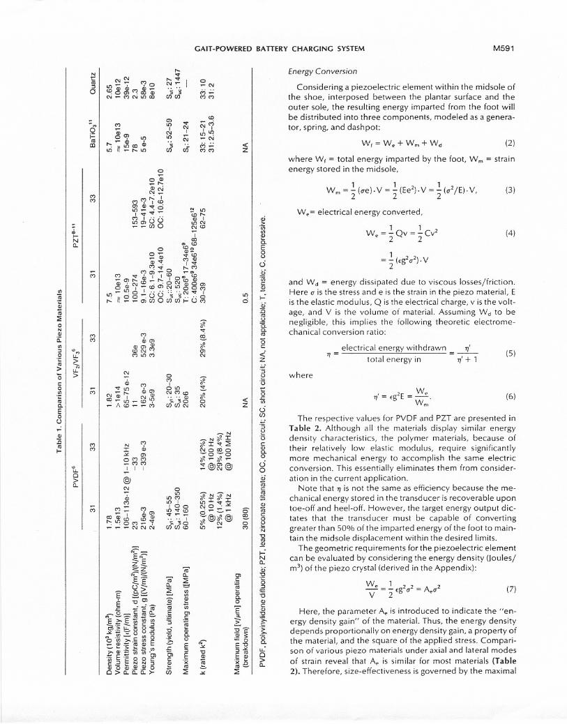
Energy Conversion
Considering a piezoelectric element within the midsole ofthe shoe, interposed between the plantar surface and theouter sole, the resulting energy imparted from the foot willbe distributed into three components, modeled as a genera-tor, spring, and dash pot:
Wf = We + Wm + Wd (2)
where W( = total energy imparted by the foot, Wm = strainenergy stored in the midsole,
1 1 2 1 2
W m = :2 (ue). V = :2 (Ee ). V = :2 (0- /E). V,(3)
cri>'enenQ)a.E0(.)
0
We= electrical energy converted,
1 1W = - Q v = - Cv2
e 2 2(4)
1
= :2 (tg20-2).V.9i'enc~~a.;:!5ro,><15.a.ro
and W d = energy dissipated due to viscous losses/friction.Here 0-is the stress and e is the strain in the piezo material, Eis the elastic modulus, Q is the electrical charge, v is the volt-age, and V is the volume of material. Assuming Wd to benegligible, this implies the following theoretic electrome-chanical conversion ratio:
(5c<iz
electrical energy withdrawn 1]'1]= =-
total energy in 1]'+ 1(5)
'Sf::'(3
0.r::.en
where
We, = tg2E= -w
.1] m
(6)
c5UJ
The respective values for PVDF and PZT are presented inTable 2. Although all the materials display similar energydensity characteristics, the polymer materials, because oftheir relatively low elastic modulus, require significantlymore mechanical energy to accomplish the same electricconversion. This essentially eliminates them from consider-ation in the current application.
Note that 1] is not the same as efficiency because the me-chanical energy stored in the transducer is recoverable upontoe-off and heel-off. However, the target energy output dic-tates that the transducer must be capable of convertinggreater than 50% of the imparted energy of the foot to main-tain the midsole displacement within the desired limits.
The geometric requirements for the piezoelectric elementcan be evaluated by considering the energy density (Joules/m3) of the piezo crystal (derived in the Appendix):
'Sf::'(3cQ)C.0c50a.;rocEQ)
roc0f::'N'0ro~~N0..a.;'0
'§~'6Q)cQ):g>,c';;:>-"6
c.u.:0>0..
We 1-- 22V -:2 tg 0- = Ae0-2
(7)
Here, the parameter Ae is introduced to indicate the "en-ergy density gain" of the material. Thus, the energy densitydepends proportionally on energy density gain, a property ofthe material, and the square of the applied stress. Compari-son of various piezo materials under axial and lateral modesof strain reveal that Ae is similar for most materials (Table2). Therefore, size-effectiveness is governed by the maximal

M592
~
ANT AKI ET Ai.
PVDP
Table 2. Derived Energy Conversion Properties
PZT8-11
Lateral(3') Axial(33)
Energy density grain, Ae [(JfPa2)/m3] (1 /2 , g2)
Maximum energy density [kJ/m3](AeIT2)
Electromechanical conversion
theoretical {2AeE} (rated k2)
VF2/VF36
31 33 BaTiO3" Quartz31 33
251-2%(1.4)
2.47e-12
" Maximum measured energy density: 200 kJ/m3 at ultimate stress.6
sustainable stress of the material, which in turn is governedby piezoelectric degradation, or depolarization, which oc-curs with repeated loading. This stress level depends uponloading rate and operating conditions, rendering it difficult todetermine definitively. Consequently, these specificationsare not commonly reported for most commercially availablepiezoelectric materials. It is in most cases considerably lowerthan the mechanical strength (i.e., yield, or ultimate strength)of the material. For example, energy densities as high as 210kJ/m3 have been reported for PVDF/ but these have beenobtained under single-action conditions wherein the mate-rial was strained to failure. Subjecting this material to cyclicloading, as would be expected in the foot generator, onecould expect to extract 25-61 kJ/m3. Thus, the total volumerequired may be excessive. The comparatively higher energydensity of PZT (as high as 83 kJ/m3) listed in Table 2 is attrib-uted to the higher estimated operating stress level.
The loading mode is an additional design consideration.The current design uses uniaxial loading because this resultsin the maximum energy conversion as compared to lateral,bending, shear, and hydrostatic loading. Because PZT ce-ramics can withstand much higher stress in compressionthan tension, due to their relatively limited fracture tough-ness, the current design uses a compressive column. Foreach heel/toe strike to generate 2.05 J of energy, in light ofthe. maximum recommended stress of approximately 10 X103 psi, 12this will require 8.5 X 10⁻⁷ m3 of PZT material.
Shoe Design
A shoe generator was designed (Figure 3) based on theabove calculations, featuring a double acting mode of oper-ation. Two longitudinal barrels house cylindrical PZT piezo-electric stacks (200 mm length, 16 mm diameter), which areactuated by hydraulic amplifiers at each end. The master pis-tons of the hydraulic amplifiers are located approximatelybeneath the tarsometatarsal joint of the forefoot and calca-neal region of the heel, and are angled to align with the max-imum reaction forces of the heel-strike (-7.80 to normal) andtoe-off (9.50). The total mechanical advantage of the systemis 35:1. Thus, 10 mm of displacement of either the heel or theforefoot translates into 0.29 mm displacement of the stack.
The applied load, which appears at a relatively low fre-quency (Figure 2), can be subdivided into any number ofsmaller "packets" to the transducer. For this purpose, a hy-draulic oscillator is incorporated into the master piston toconvert the constant stroke to a higher frequency (5X)
pulsed excitation of the stack. Although the same total en-ergy will be imparted to the mid sole, the increase in fre-quency has three beneficial effects: a reduction of the overallvolume of the transducer, an increase in the maximum al-lowable stress, and an increase in electromechanical effi-ciency.
Power Conditioning
Power delivery is determined by the relative output of theremote shoe generator to the power drawn by the electricalload. During sedentary operation, power will be transmittedalong the conventional path from the external battery sourceto the internal battery charger of the implanted device.When the shoe generator is activated, its energy will be di-rected via diode switching onto the power bus. In this con-dition its output will partially supply the power demands ofthe VAD, effectively extending the running time of the bat-tery. Should the athletic effort on the shoe generator resultin a sufficiently large power output, it is conceivable that thepower demands of the VAD will be satisfied as the externalbattery is recharged. For the current studies, a simplifiedpower conditioning circuit consisting of a bridge rectifier, abuffer capacitor, and a load resistor was configured as a basiccharge pump. The capacitor can be connected directly tothe external battery by an additional diode to provide acharging current dependent on the power delivery from the
;' l j \..
\;,.J )
('--' /"""'"
./
- == 11
HYDRAULICPULSERIAMPLIFIER
Figure 3. Schematic of shoe generator within midsole. Piezoelec-tric stack is actuated by hydraulic amplifiers coupled to heel and toe.
-"""1IIIIIIII
6.0ge-12 9.18e-13 9.7ge-12 2.1e-12 5.3e-12 1ge-18 6.6e-14
61" 0.4 4 9.5-33 24-83 - 0.32.5-5% 0.6-1% 6% 25-29% 47 -56%(2) (4) 8.4 (10-15%) (43-56%) (0.6-4%) 1%

JIll
GAIT-POWERED BATTERY CHARGING SYSTEM M593
generator. For the current studies, a digital coulombmeter(Mode! 32504; Central Scientific Co, Franklin Park, IL) wasused to measure the developed charge on the buffer capac-itOr.
The potential developed by the piezo stack is proportionalto transducer thickness. For a given volume, a tall, slenderstack will deliver a higher voltage than one with a smalleraspect ratio. By electrically coupling the piezo elements inparallel, any problem caused by high voltage would be obvi-ated. In the current application, high voltage was not a con-cern because the electric load was large enough to preventexcessive charge from building up within the crystals.
ValidationExperiments
Preliminary experiments on the PZT ceramic were con-ducted using a test cell to determine the effect of loadingand electrical impedance matching under simulated walkingdynamics. The apparatus consisted of a mechanical lever ac-tuated by an electric solenoid (Densitron, Torrence, CA)powered by a function generator to simulate various footloading conditions. Power output from the PZT element wasmeasured for different electric loads and frequencies.
A second set of experiments using a 1/17 scale model ofthe prototype midsole assembly, similar to Figure 3, was con-structed to validate the design principles postulated earlier.Thisdevice consisted of a single cylindrical stack of 18 PZTceramic slugs (PZT-5A, 0.31 inch diameter, 0.245 inch thick;Morgan Matroc, Bedford, OH) within an insulated stainlesssteel barrel. Mechanical advantage (r = 7.6) was obtained bya simplified hydraulic amplifier without oscillation.
Power output was measured for four subjects (52 kgwoman, 58 kg woman, 66 kg man, and 75 kg man) for threegaitpatterns: 1) walking at preferred cadence (approximately1 step/sec) with a natural heel contact toe-off pattern; 2)tlatfooted (both heel and toe contacting the ground simulta-neously); and 3) jogging in place (at approximately 2 steps/sec). The subjects walked in shod feet with the generatorattached to the right shoe sole and a passive orthosis at-tached to the left.
Results
The effective power transfer in the test cell was found todepend upon the stress application rate and the load imped-ance. Because the power developed on the piezoelectric el-ement was available at very high open circuit voltages (e.g.,1000V)across a relatively small capacitance (68 pF), at a lowfrequency, it was difficult to match the impedance using aresistive load. Several capacitive loads were tested to deter-minethe optimal match. An inverse relationship between ca-pacitance and developed voltage was observed. Larger ca-pacitances(e.g., 10 JLF)facilitated charge accumulation, atthe expense of power transfer. The coulombmeter providedthe most convenient means to measure charge. The rate ofloading was found to affect the peak voltage directly,whereas it appeared not noticeably to affect the total chargedeveloped.
The power generated through the walking experimentsare listed in Table 3 along with the estimated theoretic out-Put. These represent the greatest outputs observed, which
were obtained with a matched electric load. Walking exper-iments produced an average power of 5.7 :t 2.2 mW /kgbody weight, with jogging providing a higher average powerlevel of 23.6 :t 11.6 mW /kg. These results suggest that thepower generation would reach approximately 6.2 W for the75 kg subject operating a pair of full size midsole generators.
The foot contact pattern appeared minimally to influencethe power generation. Whether the subject walked with atypical heel-toe pattern versus flat-footed, the power gener-ation was not dramatically affected. However, further analy-sis needs to be performed to characterize the efficiency ofpower transfer. The point of contact with the foot was foundto influence the output primarily through its effect on the gaitpattern. When optimally aligned, the gait was most regularand electric output was maximized.
Discussion
The human body is simultaneously a consumer of energyand a power plant for interconverting energy for its contin-ued operation. As remarked by lies, "Another notable caseof efficiency in nature. . . [is] the conversion by the animalframe of fuel-values into mechanical work." B The heart andother tissues receive power from this efficient delivery sys-tem. Only when we seek artificial substitutes for our carbonbased organs must we also pursue additional energy to sup-port life.
The idea of harvesting autologous power from the contrac-tile forces of skeletal muscle is a natural approach to theproblem of limited supply of external power. This hasprompted investigators to consider applying skeletal musclefor direct actuation of ventricular assist devices. To achievecontinuous skeletal muscle power output, 14-17 however, re-quires several weeks of muscle conditioning before continu-ous power can be extracted. A much less ambitious and lessinvasive approach to harnessing power from skeletal muscleis the basis of the current study. Rather than interpose atransducer internally into the force train of the skeletal mus-cle, the current study contemplates extracting power exter-nally. A disadvantage of such an approach is that the powerwould be available only while the patient is ambulating, andonly when the special shoes are donned. Although sedentarypatients will not benefit from this on-board source of power,neither will they need to be untethered from external power.
The theoretic power estimates exceeded the recorded val-ues for moderate gait in these preliminary experiments. Theresults of the test cell experiments would indicate that thediscrepancy is the result of the uncertainties associated withthe rated piezo constants, and with the need for proper elec-trical impedance matching. The piezo characteristics arehighly dependent on experimental conditions, such as fre-quency, electrical impedance, and loading rate. The permit-tivity is also likely to increase as the limiting stress is ap-proached. Mechanical constants, such as the elastic modu-lus, are also variable. For example, as charge is drained off,further deformation in the piezo will occur. The Young'smodulus thus depends on the electric load. The shortagescould also be dramatically reduced by more advancedpower conditioning. Although power levels measured forthe simulated jogging conditions were much higher, theselevels were beyond the operating range of the device, andcould not be sustained without degrading the piezo material.

M594
~
ANTAKI ET AL.
Table 3. Measured Versus Theoretical Power Output From 1/17 Scale Model Midsole Generator
Strain energy diverted to the generator on release of soleloading would theoretically increase the energy expenditureof the patient because the shoe generator would emulateenergy absorbing sole characteristics. As a best case, the en-ergy converted in the shoe generator is analogous to energydissipated in a running shoe,5 wherein energy dissipation isdiminutive with respect to the energetics of the muscles in-volved in ambulation. As shown by Bosco and Rusko,18shoes with energy absorbing or damping soles tend to in-crease the oxygen consumption of treadmill runners. 'n thelimit, the additional perceived work introduced by the elas-ticity of the shoe may be likened to walking on a (stiff) springmattress, whereas the nonelastic component may be(roughly) compared to walking on loose sand, or a shallowstair climbing exercise.
In a conventional shoe, viscoelastic characteristics of thesole material are known to affect the distribution and levels
of strain and dissipated energy during the application andsubsequent release of foot loading. It has been estimated5that work done on the sole of a running shoe having rela-tively low stiffness and damping characteristics can be ashigh as 18 J per step. For the same sale, the elastic work re-covered is approximately 13 L whereas the remaining 5 J isdissipated.
Because the power levels involved in walking and runningdiffer significantly, there is a choice whether to size the gen-erator to accommodate the maximum expected (running)power level versus a lower level baseline. The former wouldresult in an excessively oversized shoe for normal walking. Itwould therefore be more convenient for the subject tochange shoes before running or jogging. Therefore, whenpatients anticipate the need to increase their activity level,and desire to do so without affecting their battery life, theymay choose the appropriate shoe. Besides the added poten-tial for muscle fatigue, additional factors that would influ-ence patient acceptance of this device would include stabil-ity, comfort, noise, weight, and aesthetics. These factorsshould be addressed in the production of the next genera-tion prototype.
Two main criteria for mechanical coupling from the foot tothe transducer are force transmission and loading frequency.One would expect the force to depend on compliancematching of leg to shoe and foundation.19 In fact, the forcesprove to be rather insensitive to compliance. Human feed-back appears to regulate the reaction force to achieve thedesired acceleration. Therefore, the force coupling is gov-erned primarily by the requirements for maximal energy ex-traction by the transducer. The latter requires that the devel-oped stress approximate the maximum operating strength,
and that the frequency of loading also be maximized, withinlimits.
To develop the required stress, the foot force must be Con-centrated over a relatively small area. Direct coupling is themost desirable approach for design simplicity. Unfortu-nately, this would require an extremely small cross-sectionalarea of transducer to be stressed. The consequence wouldbe an infeasible transducer length. This requirement alsoprecludes the use of a distributed transducer array in themidsole. Thus, a concentrated approach requires additionalmechanical advantage between the point of contact of thesole and the transducer. In this case, it is logical to use twocontact points for mechanical coupling. An additional advan-tage of such a concentrated transducer is that a single trans-ducer can be used for both the heel and toe, minimizingdwell time. This design also proves to be relatively insensitiveto variations in the foot contacting pattern (e.g., "heel strik-ing" versus "toe striking").2o
Although the weight of the actual transducers is not verylarge (640 g for the prototype; 40 g for the scaled model), therelated chassis, linkages, and couplings can accrue significantweight: Although the transducers could be located remotelyto the shoe (e.g., on a belt pack) with hydraulic lines couplingthem to a master piston in the midsole, an integrated designis more desirable. The hydraulic amplifiers used in the CUf-rent design allow a dramatic reduction in the axial force ex-erted on the stack housing, thus reducing the required stiff-ness (and thus weight) of the chassis, and limiting the possi-bility of jamming within the mechanical linkage.
Inasmuch as the developed power is directly proportionalto the frequency, any multiplication of frequency would di-rectly benefit an improved energy jsize ratio. In addition, thepiezo conversion characteristics are known to be sensitive tooperating frequency. Very low frequency operation (1 Hz)could impair energy conversion by as much as 50% fromoptimum. Mechanical oscillation could be accomplished inanumber of ways, including a ratchet with overrunning clutchdrive, or with hydraulic valving as in the current design. Analternative to the hydraulic pulser is a mechanical resonatOf.A resonant system would be excited by impact, and would"ring" at the resonant frequency determined by the massand elasticity of the system. This is not a very efficient formof coupling, however, because it transfers only a limited ban-dwidth of the incipient energy. The mechanical energy couldbe buffered, for example in a spring motor or flywheel, yetthese are limited both by size and efficiency loss.
In spite of the discrepancy observed in the current protO-
type between theoretic and measured power output, the refsuits of this feasibility study motivate further development 0
--oil
Measured PowerEstimated Theoretical
Subject No. Weight (kg) Gender Power (mw) Flatfoot Heel-Toe SimulatedJog-1 52 Women 421 306 256 6762 58 Women 521 156 361 9003 66 Man 664 342 225 25004 75 Man 942 625 676 2100

\
GAIT-POWERED BATTERY CHARGING SYSTEM M595
an improved full scale prototype. This will allow experiments10 be conducted to evaluate the extent to which the shoegenerator design affects the kinematics of gait and the asso-ciated energy expenditure (e.g., oxygen cost). Harmonicanalysis of torso acceleration, which has been used as an in-dex to assess relative "smoothness" of walking after limb or
joint immobilization,21 will be applied for this purpose.Because artificial prosthetic organs lack the elegance of
design displayed by the biologic systems they supplant, so100does the device described herein lack the sophistication- and power conversion efficiency of the biologic generator itisattempting to harness. This brings to mind the observationof Petroski that, "We are all engineers of sorts, for we all havethe principles of machines and structure in our bones.. . .We may wonder if human evolution may not have been thegreatestengineering feat of all time." 22
Acknowledgment
The authors thank the McGowan Foundation for their generoussupport of artificial heart and lung research at the authors' institu-tion.
References
1. Damm G, Mizuguchi K, Aber G, et al: Axial flow ventricular as-, sist cievice: system performance considerations. Artif Organs
18: 44-48, 1994.2. jarvik R, vos Savant M, Frazier OH, et al: Progress with the Jarvik
2000 Heart, in Wolner E, Schima H, Wieselthaler G (eds), 2ndCongres.~o( the International Society (or Rotary Blood Pumps,Vienna, September 23-25, 1994, p. 24.
3. Okamoto E, Tomoda K, Yamamoto K, Mitamura Y, Mikami T:1 Development of a compact, highly efficient, totally implant-! able motor-driven assist pump system. Artif Organs 18: 911-: 917, 1994.:4. Winter D: Biomechanics and Motor- Control o( Human Move-i men/, 2nd ed, New York, John Wiley & Sons, 1990.
is. Shorten M: The energetics oi running and running shoes. J Bio-i mech 26(SuppI1): 41 -51, 1993.,6. Crowe A, Schiereck P, De Boer RW, Keessen W: Characteriza-! tion of human gait by means of body center of mass oscilla-I tions derived from ground reaction iorces. IEEETram Biomed
I Eng 42: 293-303, 1995.
1
7. AMP, Inc.: A TOCHEM Sensors Technical Notes, Valley Forge,PA, AMP, Inc.
.
1
8. Morgan Matroc, Inc.: Technical Literature, Bedford, OH, Mor-gan Matroc, Inc.
f
. Piezo Systems, Ine.: Technical Literature, Cambridge, MA, PiezoSystems, Inc.
. American Piezo Ceramics, Inc.: Technical Literature, Mackey-ville, PA, American Piezo Ceramics, Inc.
. Channel Industries, Inc.: Technical Literature, Santa Barbara, CA,Channel Industries, Inc.
\. van Ri1nderi1atJ. Stetterington RE: Piezoelectric Ceramics, Eind-
hoven, The Netherlands, N.Y. Philips Gloeilampernifabrie-kan, 1974.
13. lies, G: Inventors at Work, New York, Doubleday, Page & Co.,1906, p. 263.
14. Chiu RC-J (ed): Biomechanical Cardiac Assist: Cardiomyoplastyand Muscle-Powered Devices, Mount Kisco, NY, Futura,1986.
15. Novoa R, Jacobs G, Sakakibara N, et al: Muscle powered circu-latory assist device for diastolic counterpulsator. ASAIO Trans35: 408-411, 1989.
16. Li C, Odim L Zibaitis A, Desrosiers C, Chiu RC-): Pulmonaryartery counterpulsation with a skeletal muscle power source.ASAtO J 36: M382-M386, 1990.
17. Farrar DJ: In-vivo measurements of skeletal muscle in a linearconfiguration powering a hydraulically actuated VAD. ASAIOJ 40: M309-M313, 1994.
18. Bosco C, Rusko H: The effect of prolonged skeletal musclestretch-shortening cycle on recoil of elastic energy and onenergy expenditure. Acta Physiol Scand 119: 219-224, 1983.
19. Amirouche FML, Xie M, Patwardhan A: Optimization of thecontact damping and stiffness to minimize human body vi-bration.1 Biomech Eng 116: 413-420, 1994.
20. Cavanagh PR, Lafortune MA: Ground reaction forces in distancerunning. J Biomech 13: 397-406, 1980.
21. Smidt GL, Arora JS, Johnston RC: Accelerographic analysis ofseveral types of walking.AmJ PhysMed 50: 285-300, 1971.
22. Petroski H: To Engineer Is Human, New York, St. Martins's Press,1985, p 11.
Appendix: Derivation of Electric Energy Density
The electric energy stored on internal capacitance is givenby the familiar formula:
1 1 2W =- Q v = - Cve 2 2
where the capacitance of the piezo crystal is given by:
(8)
c = E~.t
Here, Eis the permittivity, a is the electrode area, and t isthe plate separation. The potential is found by the productof the electric field density (E)and plate separation:
v = Et
(9)
(10)
where
E= gO' (11)
and g is the characteristic piezo stress constant. Substitutingequations (9), (10), and (11) into equation (8) delivers:
1 0 2
We ='2 (Eg.O')at
which is equivalent to equation (7) in the text.
(12)