Embed Size (px)
Citation preview

A fully integrated optimization framework for designing a complexgeometry offshore wind turbine spar-type floating support structureMareike Leimeister1,2, Maurizio Collu1, and Athanasios Kolios1
1Naval Architecture, Ocean and Marine Engineering, University of Strathclyde, 100 Montrose Street, Glasgow G4 0LZ,United Kingdom2Division System Technology, Fraunhofer IWES, Institute for Wind Energy Systems, Am Luneort 100, 27572 Bremerhaven,Germany
Correspondence: Mareike Leimeister ([email protected])
Abstract. Spar-type platforms for floating offshore wind turbines are considered suitable for commercial wind farm deploy-
ment. To reduce the hurdles of such floating systems to become competitive, a fully integrated optimization framework is
applied to design an advanced spar-type floater for a 5 MW wind turbine. Three cylindrical sections with individual diameters
and heights, as well as the ballast filling height are the modifiable design variables of the optimization problem. Constraints
regarding the geometry, ballast, draft, and system performance are specified. The optimization objective to minimize the floater5
structural material shall represent the overall goal of cost reduction. Preprocessing system simulations are performed to select
a critical design load case, which is used within the iterative optimization algorithm. This itself is executed by means of a
fully integrated framework for automated simulation and optimization and utilizes a genetic algorithm. The presented design
optimization example and approach emphasize the complexity of the optimization problem and lead to the recommendation
to consider safety factors for other more critical and design-driving performance criteria. For the applied methodology and10
conditions it is shown that the required material for an advanced spar-type platform supporting an offshore wind turbine can be
reduced by more than 31% and, at the same time, the performance of the floating system - expressed by the maximum system
inclination, maximum tower top acceleration, and mean translational motion - improved in some respect.
Abbreviations: AEP, Annual Energy Production; ALPSO, Augmented Lagrangian Particle Swarm Optimization; BC, Base Column; BClow, Base
Column lower part; BCmid, Base Column middle part; BCup, Base Column upper part; CapEx, Capital Expenditure; COBYLA, Constrained Optimization
BY Linear Approximation; DLC, Design Load Case; DNV GL, Det Norske Veritas and Germanischer Lloyd; Dymola, Dynamic Modeling Laboratory; IEC,
International Electrotechnical Commission; IWES, Institute for Wind Energy Systems; LCoE, Levelized Cost of Energy; MoWiT, Modelica for Wind Turbines;
NREL, National Renewable Energy Laboratory; NSGAII, Non-dominated Sorting Genetic Algorithm II; NSGAIII, Non-dominated Sorting Genetic Algorithm
III; OC3, Offshore Code Comparison Collaboration; OC4, Offshore Code Comparison Collaboration Continuation; OpEx, Operational Expenditure; Rkfix4,
Runge-Kutta fixed-step and 4th order method; SPEA2, Strength Pareto Evolutionary Algorithm 2; SWL, Still Water Level; TI, Turbulence Intensity; TP,
Tapered Part; UC, Upper Column
1
https://doi.org/10.5194/wes-2020-93Preprint. Discussion started: 26 June 2020c© Author(s) 2020. CC BY 4.0 License.

1 Introduction
With floating support structures for offshore wind turbines, more offshore wind resources can be captured and used for power
generation, as around 60% to 80% of the ocean areas cannot be exploited with bottom-fixed structures, which are limited
to water depths of up to around 50 m (European Wind Energy Association, 2013). The floating offshore wind technology
is no longer in its infancy. Over the last decade, the technology readiness level of floating offshore wind turbine systems20
has significantly increased so that “floating offshore wind is coming of age”, as WindEurope states in its floating offshore
wind vision statement (WindEurope, 2017, p.4). The large number of research studies, research projects, scaled model tests,
prototype developments, and full scale model test phases paved the way towards this current status. More than 30 floating
foundation concepts exist and are under development (Quest Floating Wind Energy, 2020; Future Power Technology, 2019;
James and Ros, 2015; Mast et al., 2015). A few selected milestones are (Löfken, 2019)25
– the Hywind spar-buoy floating system, with a 2.3 MW demonstrator deployed in 2009, the subsequent Hywind Scotland
pilot park of five 6 MW turbines operating since 2017, and another wind farm Hywind Tampen with eleven 8 MW
turbines planned for 2022;
– the WindFloat semi-submersible floating system by Principle Power, with three 2 MW demonstrators since 2011 and
twelve large projects planned for the upcoming years with turbines of up to 8.4 MW;30
– the Damping Pool® (Floatgen) barge floating system by Ideol, with a 2 MW and a 3 MW demonstrator since 2018 and
further large projects with for example 6.2 MW wind turbines planned for the future; and
– the TetraSpar spar, semi-submersible, or tension leg platform floating system by Stiesdal Offshore Technologies, with a
demonstrator supporting a 3.6 MW wind turbine planned for spring 2020.
Despite the great amount of floating offshore wind projects, most of them are under development and currently the Hywind35
Scotland pilot park is the one and only operational floating wind farm (Future Power Technology, 2019). More are planned
as already mentioned above; however, for further speed-up of the market uptake of floating offshore wind farms, significant
cost-reductions are still required. From the survey-based study by Leimeister et al. (2018) the conclusion is drawn that the spar-
buoy concept is the most mature and has the highest technology readiness level. However, in order to enhance its suitability
for multi-MW wind farm deployment, this technology has to be further advanced: The common spar-buoy floater is already40
very convenient for volume production and certification due to its simple geometry, but to facilitate an accelerated and global
market uptake, especially the large floater draft has to be reduced, so that in the end the levelized cost of energy (LCoE) is
reduced and the handling simplified.
To overcome the challenges that the highly promising spar-buoy floating platform type still faces, a few researchers have
already worked on concepts for spar-type floating offshore wind turbine support structures, which have a reduced draft but45
still provide sufficient stability (Wright et al., 2019; Yoshimoto and Kamizawa, 2019; Zhu et al., 2019; Hirai et al., 2018;
Yoshimoto et al., 2018; Yamanaka et al., 2017; Matsuoka and Yoshimoto, 2015; Lee, 2005). However, different approaches
2
https://doi.org/10.5194/wes-2020-93Preprint. Discussion started: 26 June 2020c© Author(s) 2020. CC BY 4.0 License.

for designing the floating platform were followed and it does not seem that a fully integrated optimization approach has been
adopted. Thus, the aim of this paper is to demonstrate that, through a more comprehensive fully integrated design optimization
approach and by allowing design variables out of a wider range of values, more potential solutions for an advanced spar-50
type floater design can be captured. Apart from reducing the floater draft, the main objective is cost reduction - expressed in
terms of the material used - while global system performance criteria have to be fulfilled. All these requirements regarding
design variables and optimization criteria are - together with specific environmental conditions and the fully-coupled aero-
hydro-servo-elastic dynamic characteristics of a floating offshore wind turbine system - incorporated into a fully integrated
optimization framework. By means of this, an advanced spar-type floating offshore wind turbine support structure design is55
aimed to be obtained. The focus of the optimization procedure lies on hydrodynamic and system-level analyses and no further
limitations regarding a high detail structural design are added. This way and by considering different structural realization
approaches for the resulting optimized geometries, new alternatives of potential and innovative floater design solutions are
opened up.
In order to figure out in detail the required characteristics of such a floating platform, first, advanced spar-type floating wind60
turbine support structures are elaborated in detail in Sect. 2 and a reference floating system with corresponding assessment cri-
teria is specified. Based on this, the optimization problem - consisting of design variables, objective function, and constraints -
is defined in Sect. 3. Subsequently, the automated design optimization of the advanced spar-type floating wind turbine system
is performed in Sect. 4, including some preprocessing automated design load case (DLC) simulations, as well as the charac-
terization of the automated optimization framework and the iterative optimization approach. The results of the optimization65
simulations are presented in Sect. 5 and further discussed in Sect. 6. Finally, some conclusions are drawn in Sect. 7.
2 Advanced spar-type floating wind turbine support structures
According to the survey conducted by Leimeister et al. (2018), industry professionals and scientific experts judge the advanced
spar-type floating platform - compared to the common spar-buoy floaters, semi-submersibles, tension leg platforms, barges or
any hybrid, multi-turbine, or mixed-energy floating system - to be the most suitable support structure for wind turbines to be70
deployed in floating offshore wind farms due to their suitability for serial production, possibility of receiving certification, low
LCoE, and little demands on the mooring system.
2.1 Characteristics of advanced spar-type floaters
The common spar-buoy floating platform consists of a long relatively slender cylinder which is filled at the bottom end with
ballast. The resulting deep center of gravity provides stability against overturning. However, this floating system exhibits some75
weaknesses: Due to its deep draft it cannot be deployed in shallow or intermediate waters up to around 100 m (James and Ros,
2015), nor can the entire floating wind turbine system be fully assembled in upright position onshore or at harbor sites. The
latter fact adds to the already expensive floater, as it makes the overall handling of this long and heavy structure, its assembly,
transport, and installation costly. Thus, by
3
https://doi.org/10.5194/wes-2020-93Preprint. Discussion started: 26 June 2020c© Author(s) 2020. CC BY 4.0 License.

– reducing the draft,80
– applying a delta or so called crowfoot connection of the mooring lines to the spar-buoy structure, and/or
– adding damping fins
the advanced spar-type floating system can benefit from
– a wider range of possible installation sites,
– simplified handling (both construction, assembly, transport, and installation),85
– reduced system, as well as construction and transportation costs, as well as
– improved system motion performance. (Leimeister et al., 2018)
In particular, these characteristics of advanced spar-type floating platforms are realized in a few - both research and real -
concepts. The advanced spar floater by the Massachusetts Institute of Technology (Lee, 2005) has a relatively shallow draft
and gets stability support from a two-layered taut-leg mooring system (Butterfield et al., 2007). Both Yamanaka et al. (2017)90
and Hirai et al. (2018) use a three-segmented advanced spar, where a larger diameter column makes up the middle part to allow
for shortening the overall length of the spar and reducing the system cost, while Zhu et al. (2019) utilize the three elements just
in an opposite way, focusing on increased restoring and improved motion performance: the spar element makes up the middle
part and interconnects two columns, one with just a slightly larger diameter at the bottom end and another one with a large
diameter at the upper end.95
Within the Fukushima Floating Offshore Wind Farm Demonstration Project FORWARD an advanced spar-type support
structure, developed by Japan Marine United, is utilized for a floating substation (Fukushima Kizuna) and a 5 MW wind turbine
(Fukushima Hamakaze) (Main(e) International Consulting LLC, 2013; James and Ros, 2015; Yoshimoto and Kamizawa, 2019).
The advanced spar for the floating substation consists of three columns - or so called hulls - placed at the bottom, in the middle,
and at the upper end (intersecting the water line) of the spar, so that the floating system is suitable already at around 110 m100
water depth, the motion performance is improved, and the cost for installation is reduced (Wright et al., 2019; Yoshimoto et al.,
2018; Matsuoka and Yoshimoto, 2015). The Fukushima Hamakaze was initially using a similarly structured advanced spar,
equipped with damping fins for stabilization in sway and heave direction (Main(e) International Consulting LLC, 2013; James
and Ros, 2015); however, after some investigations and studies by Matsuoka and Yoshimoto (2015), finally the advanced spar-
type platform for the 5 MW wind turbine consists of just two large columns/hulls at the bottom and top end of the spar and,105
thus, is optimized with respect to the system restoring and motion performance, as well as the construction cost (Yoshimoto
and Kamizawa, 2019).
2.2 Reference floating offshore wind turbine system
As starting point of the design optimization towards an advanced spar-type floating platform for an offshore wind turbine, a
traditional spar-buoy floating wind turbine system, taken from phase IV of the OC3 (Offshore Code Comparison Collaboration)110
4
https://doi.org/10.5194/wes-2020-93Preprint. Discussion started: 26 June 2020c© Author(s) 2020. CC BY 4.0 License.

project (Jonkman, 2010), is used and modified, as explained in Sect. 2.3, to allow the development of an advanced spar-type
structure.
The OC3 phase IV floating offshore wind turbine system consists of
– the NREL (National Renewable Energy Laboratory) 5 MW reference wind turbine (Jonkman et al., 2009) with a rotor
diameter of 126.0 m, a hub height of 90.0 m, an overall mass of the rotor-nacelle assembly of 350,000 kg, and an115
operating range between 3.0 m/s and 25.0 m/s with rated wind speed at 11.4 m/s;
– an offshore adapted tower (Jonkman, 2010) ranging from 10.0 m elevation above still water level (SWL) up to 87.6 m,
which is tapered from a diameter and wall thickness of 6.5 m and 0.027 m, respectively, at the base to a diameter and
wall thickness of 3.87 m and 0.019 m, respectively, at the top and weighs 249,718 kg;
– the spar-buoy floater (Jonkman, 2010) with a top diameter of 6.5 m at 10.0 m elevation above SWL, which increases120
between 4.0 m below SWL and 12.0 m below SWL up to 9.4 m, which corresponds to the diameter at the base at 120.0 m
below SWL, and an overall mass - including ballast - of 7,466,330 kg; and
– three evenly spaced catenary mooring lines of 902.2 m length each and 0.09 m diameter, which are attached to the spar-
buoy at 70.0 m below SWL and anchored to the seabed at 320.0 m water depth in a radius of 853.87 m from the floater
centerline (Jonkman, 2010).125
2.3 Modifications for defining an advanced spar-type floater
An aero-hydro-servo-elastic coupled model of dynamics for this original OC3 phase IV spar-buoy floating wind turbine sys-
tem is developed and verified by Leimeister et al. (2020a), using the MoWiT (Modelica for Wind Turbines) library (Leimeister
and Thomas, 2017; Thomas et al., 2014; Strobel et al., 2011). The modeling approach in MoWiT utilizes the object-oriented,
equation-based, and component-based modeling language Modelica1 and therefore follows a hierarchical structure with in-130
terconnected main components and subcomponents to represent the complex wind turbine system and fully-coupled system
dynamics. This multibody approach provides high flexibility to model various wind turbine system types, environmental con-
ditions, and simulation settings by simply modifying single model components. The MoWiT library, developed at Fraunhofer
IWES (Institute for Wind Energy Systems), is continuously enhanced and more features and interfaces are added, which opens
up a broad application range, including the integration into a framework for automated simulation and optimization, as utilized135
in this study. (Leimeister et al., 2020b)
This MoWiT model of the OC3 phase IV spar-buoy floating wind turbine system is used as basis and modified so that a
design of an advanced spar-type floater can be obtained through automated optimization. As this work focuses on the design of
the floating platform and not on the mooring system, a shorter, less heavy, and hence cheaper advanced spar-type floater design
shall be obtained by changing the floater geometry. Different characteristic shapes of advanced spar-type floating platforms140
are pointed out in Sect. 2.1. In this study, a similar concept as presented by Zhu et al. (2019) and realized in the Fukushima
1https://www.modelica.org/ (Accessed: 22 January 2020)
5
https://doi.org/10.5194/wes-2020-93Preprint. Discussion started: 26 June 2020c© Author(s) 2020. CC BY 4.0 License.
Hamakaze floating wind turbine system (Matsuoka and Yoshimoto, 2015; Yoshimoto and Kamizawa, 2019) is applied: the
long cylindrical element below the tapered part is divided into three partitions
1. the base column upper part BCup, which shall serve for gaining buoyancy;
2. the base column middle part BCmid, which mainly provides the separation of parts 1 and 3 to deepen the position of part145
3; and
3. the base column lower part BClow, which can be filled with ballast and this way shall shift the center of gravity down-
wards.
Figure 1. Geometrical definitions of the ad-
vanced spar-type floating platform.
This partitioning is schematically represented in Fig. 1, showing the unchanged
geometric parameters and dimensions for the upper column (UC) and tapered part150
(TP) in a light shade (gray) and indicating the three sections of the base column (BC)
together with the ballast filling in the base column lower part BClow. In order to still
represent the original OC3 phase IV floating spar-buoy with the modified MoWiT
model, initially the diameters of all three BC parts are set equal to the original spar
diameter of 9.4 m and - as a ballast filling is just allowed in BClow - the heights of155
BCup and BCmid are set equal to machine epsilon, which corresponds to a value of
10−15 in Modelica, while BClow holds the full original length of 108 m. Regarding
the hydrodynamic coefficients for the three cylindrical partitions, the same as for
the original OC3 phase IV spar-buoy (Jonkman, 2010) are applied.
Apart from these modifications, which are directly related to an advanced spar-160
type floater design, also the material density of the support structure and the wall
thickness of the cylindrical spar-buoy elements are changed. As the material density
of the OC3 phase IV spar-buoy is not explicitly defined in the definition document
(Jonkman, 2010), a value of 10,000 kg/m3 is derived in the model verification study
(Leimeister et al., 2020a). However, to better match the common steel properties of165
offshore structures, a material density of 7,850 kg/m3 is used for the design of the
advanced spar-type floating platform. Furthermore, the wall thickness of the spar
structure2 is changed from the fixed value of 0.0314 m, which is derived by Leimeister et al. (2020a), to a wall thickness
which is adaptable to the specific advanced spar-type floater design. In order to obtain an appropriate wall thickness for a
corresponding floater design, a fixed ratio of the support structure structural mass to the displaced mass of water is deployed,170
which is according to representative values from research designs and academic studies for a spar-type floating platform 0.13
(Bachynski, 2018). Hence, the equivalent structural mass of the advanced spar floater (meaning the mass of the advanced spar-
type steel structure excluding the tower and wind turbine, and as well excluding the ballast mass) with certain outer dimensions2Referring here purely to the circumferential walls of the hollow cylindrical or conical elements, as for base and lid a fixed marginal cap thickness of
0.001 m is applied, according to the implemented model in the verification study (Leimeister et al., 2020a).
6
https://doi.org/10.5194/wes-2020-93Preprint. Discussion started: 26 June 2020c© Author(s) 2020. CC BY 4.0 License.

(diameters Di and heights Hi) and corresponding displaced volume can be determined following Eq. (1).
spar structural massbuoyancy mass
= 0.13 (1)175
With the resulting structural mass of the advanced spar-type floater of 1.070E+06 kg, which is a bit lower than the original
structural mass of 1.150E+06 kg (Leimeister et al., 2020c), the corresponding appropriate wall thickness, which is kept the
same and constant for all parts of the specific advanced spar design, is computed by means of Eq. (2), which is derived from
the expression for the mass of the advanced spar steel structure with a material density of 7,850 kg/m3 as explained above.
In Eq. (2), Hi and Di are the heights and diameters of each element, meaning UC, TP, BCup, BCmid, and BClow, while the180
diameter of the tapered part DTP is determined according to Eq. (3) as mean of the diameters of UC and BCup.
wall thickness =
∑i (HiDi)−
√[∑i (HiDi)]
2− 4π
spar structural massmaterial density
∑iHi
2∑iHi
(2)
DTP =DUC + DBC,up
2(3)
This way, a wall thickness of 0.0372 m is obtained for the original OC3 phase IV spar-buoy with reduced material density
(7,850 kg/m3) and adopted structural mass to displaced mass ratio of 0.13. This wall thickness value lies within the acceptable185
range, based on available data for the semi-submersible floating platform from phase II of OC4 (Offshore Code Comparison
Collaboration Continuation).
As the advanced spar-type floater design (optimization) study does not focus on the mooring system, as mentioned above
and due to the fact that the mooring system itself could be covered in a separate optimization task, any change in the restoring
system characteristics due to shifted fairlead positions is prevented by utilizing constant (the original) resulting mooring sys-190
tem properties. This means that - independent of possible attachment points to the reshaped floating platform - the resulting
mooring stiffness is taken from the system motion, assuming the original fairlead positions as defined in Sect. 2.2. By doing
so, further system performance improvements due to modified mooring system parameters or fairlead positions - in addition to
an optimized support structure design - are limited. This, however, leaves open the possibility of subsequent fine tuning of the
design solution obtained through optimization based on hydrodynamic and system-level analyses.195
2.4 Assessment criteria for designing an optimized advanced spar-type floater
The focus in this study lies on obtaining an advanced spar-type floating platform, which is characterized through a limited draft
and reduced structural cost, but still shows good hydrodynamic performance. Any detailed structural integrity checks are not
addressed in this work, but can be added for a more extensive optimization approach. However, by focusing only on hydro-
dynamics and global system performance without defining any restrictions regarding structural aspects, floater designs, which200
would have been discarded when performing structural integrity checks and as they would be unfeasible to be realized with
conventional structural approaches, can still be captured as potential solutions when considering different structural realization
approaches.
7
https://doi.org/10.5194/wes-2020-93Preprint. Discussion started: 26 June 2020c© Author(s) 2020. CC BY 4.0 License.

The only structural related focus, considered in this approach, is the minimization of the structural cost. This is represented
through the steel volume of the floater, which is finally specified as objective of the optimization problem, as formally declared205
in Sect. 3.2.
In order to achieve the shortened length of the advanced spar-type floater, the allowable draft of the system is limited to the
original draft of the OC3 phase IV floating wind turbine system as maximum value, as well as to a recommended minimum
value of 15.0 m (Ng and Ran, 2016). The resulting allowable total height of the BC has to be distributed to the three partitions.
As, however, this distribution is not restricted, keeping also the option of utilizing not all three BC parts, the minimum allowable210
value for the height of each of the BC parts is machine epsilon - as a zero value is unfeasible from a modeling point of view. For
the ballast height, it additionally has to be guaranteed that it does not exceed the actual BClow height. The resulting allowable
value ranges based on the draft limits are summarized in Table 1.
Table 1. Allowable value ranges addressing the draft limits.
Allowable draft Resulting total height of BC BCup height BCmid height BClow height Ballast height
Min 15.0 m 3.0 m 10−15 10−15 10−15 10−15
Max 120.0 m 108.0 m 108.0 m 108.0 m 108.0 m 108.0 m
The applied concept of a three-segmented advanced spar-type floater with elements for buoyancy, distance, and ballast
shall not only allow different heights but also different diameters of these elements. Thus, the allowable value range for the215
diameter of each of the BC parts is set from machine epsilon - due to the same modeling feasibility reason - to 120.0 m. The
maximum diameter is chosen deliberately large - corresponding to the total maximum draft of the floating system - to ensure
that the border of feasible solutions is well captured. From the manufacturing point of view, cylindrical offshore structures
with diameters of more than 10.0 m are realistic: various sources3,4 state a value of 11.0 m, the reference semi-submersible
floating platform from phase II of OC4 has an upper column diameter of 12.0 m (Robertson et al., 2014), and the diameter220
of the spar-buoy utilized in the Hywind Scotland floating wind farm5,6 is even up to 14.5 m large. However, looking at other
floating platform solutions, such as the Damping Pool® floater by Ideol7 with outer dimensions of 36 m x 36 m and a resulting
diagonal length of almost 51 m or again the OC4 phase II semi-submersible platform (Robertson et al., 2014) with an overall
outer dimension of almost 82 m in diameter, shows that floating structures with a large overall outer diameter can be obtained
without being restricted to the manufacturing feasibility limits for pure cylinders. Thus, from a hydrodynamic point of view,225
a cylindrical offshore structure with very large diameter can be realized as well through several smaller diameter cylinders
3https://sif-group.com/en/wind/foundations (Accessed: 13 August 2019)4https://www.windkraft-journal.de/2019/06/14/steelwind-nordenham-ist-von-wpd-die-gruendungsstrukturen-fuer-den-offshore-wind-park-yunlin-in-
taiwan-zu-fertigen/136551 (Accessed: 13 August 2019)5https://www.equinor.com/content/dam/statoil/documents/newsroom-additional-documents/news-attachments/brochure-hywind-a4.pdf (Accessed: 13
June 2019)6https://www.equinor.com/en/news/worlds-first-floating-wind-farm-started-production.html (Accessed: 13 June 2019)7https://floatgen.eu/ (Accessed: 13 August 2019)
8
https://doi.org/10.5194/wes-2020-93Preprint. Discussion started: 26 June 2020c© Author(s) 2020. CC BY 4.0 License.

being clustered together in a circle, representing similar hydrodynamic behavior and characteristics. Finally, attention has to
be drawn on the minimum possible diameter of the BC parts, which always has to be at least as large as twice the actual wall
thickness corresponding to the specific advanced spar-type floater design.
Having modified the diameters and heights of the three BC parts, as well as the ballast filling height, and having adjusted230
the wall thickness according to the structural mass to displaced mass ratio, as defined in Sect. 2.3, the ballast density has to
be adjusted to match the original floating equilibrium between buoyancy force, system weight, and downward mooring force,
so that the original hub height is maintained. In order to exclude unfeasible system solutions, in which material would have
to be removed from the system (realized for example by reducing the material density) to meet this equilibrium condition, it
has to be ensured that the actual resulting ballast density of the specific advanced spar-type floater design carries a positive235
value. However, in order to account for truly realistic ballast densities, also the uppermost allowable value of the ballast density
has to be constrained. Leimeister et al. (2020c) have explored within a first-stage design optimization application example
densities for common and cheap materials to be used as ballast for a floating spar-buoy. The densest material included is
sandstone (or other rocks) with a density of about 2.6E+03 kg/m3. Apart from sand, sand mixed with water, concrete, or rocks,
MagnaDense (heavyweight concrete) is as well used in industry as high density material8,9,10. With MagnaDense densities240
of up to 5.0E+03 kg/m3 can be obtained11 (LKAB Minerals, 2019). Even if minimization of the structure material volume is
defined as objective function - as stated at the beginning of this section - in order to represent the structural cost, the cost of
the two potential densest ballast materials is elaborated to avoid significant larger ballast costs when utilizing MagnaDense
instead of the common cheap materials pointed out by Leimeister et al. (2020c). However, when comparing the material
prices for sandstone12 (for the ballast density limit of 2.6E+03 kg/m3) and MagnaDense8,13 (for the ballast density limit of245
5.0E+03 kg/m3), it turns out that both ballast materials have a similar cost of around 150 $ per ton, which is less than 20% of
the material cost for structural (raw) steel of about 700 $ per tonne14 (Grogan, 2018; Butcher, 2018). Thus, the ballast density
is constrained to a maximum of 5.0E+03 kg/m3.
Apart from these more geometry related assessment criteria, there are three performance related criteria, which the advanced
spar-type floating offshore wind turbine system has to fulfill. For the global system performance of a floating offshore wind250
turbine maximum allowable values are prescribed for
1. the total inclination angle of the system to the vertical:
for system rotational stability reasons a maximum total inclination angle of 10.0◦ is allowed in operational conditions
(Leimeister et al., 2020c; Katsouris and Marina, 2016; Kolios et al., 2015; Huijs et al., 2013);
8Floating offshore wind project manager at a leading company in offshore industry, personal communication, 6 February 20209https://www.lkabminerals.com/en/industry-uses/offshore-energy/offshore-wind-structures/ (Accessed: 7 June 2020)
10https://www.lkabminerals.com/de/floating-offshore-wind-2018/ (Accessed: 7 June 2020)11https://www.lkabminerals.com/wp-content/uploads/2019/02/MagnaDense-SDS-12-06INT-19-03.pdf (Accessed: 5 February 2020)12https://www.alibaba.com/showroom/sandstone-price-per-ton.html (Accessed: 5 February 2020)13https://german.alibaba.com/product-detail/magnadense-heavy-concrete–172429386.html (Accessed: 5 February 2020)14https://spendonhome.com/structural-steel-fabrication-cost/ (Accessed: 5 February 2020)
9
https://doi.org/10.5194/wes-2020-93Preprint. Discussion started: 26 June 2020c© Author(s) 2020. CC BY 4.0 License.

2. the total horizontal acceleration at the tower top:255
due to sensitive components in the nacelle and to prevent any issues with the lubrication, the nacelle acceleration -
corresponding to the acceleration at the tower top - is limited, depending on the specific wind turbine, to a maximum of
0.2 to 0.3 times the gravitational acceleration constant (Nejad et al., 2017; Huijs et al., 2013; Suzuki et al., 2011); herein
the lower value of 1.962 m/s2 is used following a conservative approach (Leimeister et al., 2020c); as well as
3. the mean translational motion of the floating system:260
based on experience, the static translational displacement of a (non TLP-type) floating offshore wind turbine system,
corresponding to the mean of the translational motion, is restricted to 0.2 times the water depth (320.0 m in the case of
the OC3 phase IV spar-buoy floating system), and hence to 64.0 m in this application (Leimeister et al., 2020c).
3 Definition of the optimization problem
For obtaining an optimized advanced spar-type floater design following the assessment criteria - as outlined in Sect. 2.4 - and265
using the modified floating wind turbine system model - as described in Sect. 2.3 - as basis, an iterative optimization approach
(explained in more detail in Sect. 4.3) is carried out in this study. This optimization approach requires the definition of the
optimization problem - comprising the modifiable design variables xi, the objective functions fi to be minimized, as well as
the equality (hi) and inequality (gi) constraints to be fulfilled - as given in formal expressions in the following:
find X = {x1, ...,xk}
to minimize fi(X,system(X)) , i = 1, ..., l
subject to hi(X,system(X)) = 0 , i = 1, ...,m
subject to gi(X,system(X))≤ 0 , i = 1, ...,n
270
The functions are either directly depend on the design variables or also on the resulting fully-coupled complex floating
offshore wind turbine system, denoted with system(X).
3.1 Design variables of the advanced spar floating wind turbine system
Based on the derivation of the modified spar-buoy floater model for enabling the design of an advanced spar-type floating
platform (Sect. 2.3), the design variables vector X = {x1,x2, ...,x6,x7} with the following seven (k = 7) elements is defined:275
– x1, the diameter of BCup;
– x2, the diameter of BCmid;
– x3, the diameter of BClow;
– x4, the height of BCup;
10
https://doi.org/10.5194/wes-2020-93Preprint. Discussion started: 26 June 2020c© Author(s) 2020. CC BY 4.0 License.

– x5, the height of BCmid;280
– x6, the height of BClow; and
– x7, the ballast height.
3.2 Objective function for the advanced spar floating wind turbine system
As stated in Sect. 2.4, just one objective function (l = 1) is specified, which corresponds to the structure material volume of the
advanced spar-type floating platform. This objective function (f1) is to be minimized, as defined at the beginning of Sect. 3.285
3.3 Constraints for the advanced spar floating wind turbine system
Section 2.4 covers already the assessment criteria for designing an optimized advanced spar-type floating platform. These make
up - apart from the objective function - 25 constraints, which are all specified as inequality constraints - hence, m = 0 (for the
equality constraints hi) and n = 25 (for the inequality constraints gi). These shall all take on values less or equal to zero, as
expressed at the beginning of Sect. 3. The definitions of the inequality constraints are listed in Table2.290
4 Automated design optimization of the advanced spar-type floating wind turbine system
The final automated design optimization of the reference advanced spar-type floating wind turbine system described in Sect. 2.3
consists of
1. preprocessing automated system simulations for identifying the simulation conditions to be considered within the opti-
mization (Sect. 4.1), as well as295
2. the actual iterative optimization approach for obtaining an optimized advanced spar-type floating platform design (Sect. 4.3).
Both utilize a framework for automated simulation and optimization developed at Fraunhofer IWES and presented in Sect. 4.2.
4.1 Preprocessing automated system simulations
Standardization and classification bodies, such as IEC (International Electrotechnical Commission) and DNV GL (Det Norske
Veritas and Germanischer Lloyd), give recommendations on DLCs to be considered when designing floating offshore wind300
turbine systems. Thus, in the technical specification IEC TS 61400-3-2 (International Electrotechnical Commission, 2019b),
based on the international standard IEC 61400-3-1 (International Electrotechnical Commission, 2019a), and in the standard
DNVGL-ST-0119 (DNV GL AS, 2018), building on the standard DNVGL-ST-0437 (DNV GL AS, 2016), a substantial number
of DLCs is listed which cover different operating states at various environmental conditions. When performing an iterative de-
sign optimization approach, however, it is not practical to simulate for each design considered within the iterative optimization305
approach the full set of DLCs. This is not only for reasons of high computational effort, but also due to the fact that not all
DLCs might be relevant and driving the design for the specified optimization problem.
11
https://doi.org/10.5194/wes-2020-93Preprint. Discussion started: 26 June 2020c© Author(s) 2020. CC BY 4.0 License.

Table 2. Definition of the 25 inequality constraints.
Inequality constraint Formal expression Description
g1 10−15 m−x1 Allowable value range of x1
g2 x1 − 120.0 m Allowable value range of x1
g3 10−15 m−x2 Allowable value range of x2
g4 x2 − 120.0 m Allowable value range of x2
g5 10−15 m−x3 Allowable value range of x3
g6 x3 − 120.0 m Allowable value range of x3
g7 10−15 m−x4 Allowable value range of x4
g8 x4 − 108.0 m Allowable value range of x4
g9 10−15 m−x5 Allowable value range of x5
g10 x5 − 108.0 m Allowable value range of x5
g11 10−15 m−x6 Allowable value range of x6
g12 x6 − 108.0 m Allowable value range of x6
g13 10−15 m−x7 Allowable value range of x7
g14 x7 − 108.0 m Allowable value range of x7
g15 max(total inclination angle)− 10.0◦ Maximum total inclination angle
g16 max(horizontal nacelle acceleration)− 1.962 m/s2 Maximum horizontal nacelle acceleration
g17 mean(translational motion)− 64.0 m Mean translational motion
g18 3.0 m− (x4 + x5 + x6) Minimum draft
g19 x4 + x5 + x6 − 108.0 m Maximum draft
g20 x7 −x6 Ballast filling height within BClow
g21 −ballast density Allowable value range of the ballast density
g22 ballast density− 5.0E+03 kg/m3 Allowable value range of the ballast density
g23 0.5 · 10−15 m+ wall thickness− 0.5x1 Wall thickness and diameter of BCup
g24 0.5 · 10−15 m+ wall thickness− 0.5x2 Wall thickness and diameter of BCmid
g25 0.5 · 10−15 m+ wall thickness− 0.5x3 Wall thickness and diameter of BClow
Thus, in this work, the same approach as taken by Leimeister et al. (2020c) in another design optimization application
example is adopted. In this, first, a limited number of DLCs, critical for the considered floating offshore wind turbine system
and design optimization problem, is selected - a common approach in research studies (Leimeister et al., 2020c; Krieger et al.,310
2015; Matha et al., 2014; Huijs et al., 2013; Bachynski et al., 2013; Bachynski and Moan, 2012; Suzuki et al., 2011). For the
considered advanced spar-type floating offshore wind turbine system, described in Sect. 2, and the corresponding optimization
problem stated in Sect. 3, three DLCs according to IEC 61400-3-1 (International Electrotechnical Commission, 2019a) are
selected (Leimeister et al., 2020c):
12
https://doi.org/10.5194/wes-2020-93Preprint. Discussion started: 26 June 2020c© Author(s) 2020. CC BY 4.0 License.

– DLC 1.1 around rated wind speed (explicitly at 10.0 m/s, 11.4 m/s, and 13.0 m/s), as well as315
– DLC 1.3 and
– DLC 1.6, both at 8.0 m/s, 11.4 m/s (rated wind speed), and 25.0 m/s (cut-out wind speed).
These are chosen to cover highest thrust loads and corresponding system inclination and mean translational displacement
at rated wind speeds, as well as maximum dynamic responses in extreme turbulent wind conditions or at severe irregular sea
states, as the maximum total inclination angle, the maximum horizontal nacelle acceleration, and the mean translational motion320
make up three (g15, g16, and g17) of the optimization constraints defined in Sect. 3.3, which need to be checked and adhered to.
From these selected three DLCs, 54 environmental conditions are defined, which correspond to 18 different environmental
settings per DLC as summarized in Table 3. Thus, in each DLC turbulent wind with three different mean wind speeds and cor-
responding longitudinal turbulence intensity (TI) are considered. Per wind speed six different wind seed numbers are accounted
to capture the randomness of turbulent wind. Three different yaw misalignment angles are used and combined with two seeds325
each to reduce the overall number of simulation cases. The irregular sea state, prevailing in all three DLCs, is specified through
the significant wave height and peak period. Furthermore, each realization of the turbulent wind with a different wind seed uses
as well a different wave seed to represent again the randomness of irregular waves. Finally, a current speed is specified for each
wind speed.
Table 3. System parameters for preprocessing simulations of selected DLCs (Leimeister et al., 2020c).
DLCWind conditions Sea conditions*
Wind speed Long. TI Wind seed Yaw misalignment Sign. wave height Peak period Current speed
1.1
10.0 m/s 18.34% 1 ... 6 -8◦, 0◦, 8◦ 1.74 m 6.03 s 0.074 m/s
11.4 m/s 17.38% 7 ... 12 -8◦, 0◦, 8◦ 1.99 m 6.44 s 0.084 m/s
13.0 m/s 16.53% 13 ... 18 -8◦, 0◦, 8◦ 2.30 m 6.92 s 0.096 m/s
1.3
8.0 m/s 35.00% 1 ... 6 -8◦, 0◦, 8◦ 1.44 m 5.48 s 0.059 m/s
11.4 m/s 26.97% 7 ... 12 -8◦, 0◦, 8◦ 1.99 m 6.44 s 0.084 m/s
25.0 m/s 16.68% 13 ... 18 -8◦, 0◦, 8◦ 4.94 m 10.14 s 0.184 m/s
1.6
8.0 m/s 20.30% 1 ... 6 -8◦, 0◦, 8◦ 10.37 m 14.70 s 0.059 m/s
11.4 m/s 17.38% 7 ... 12 -8◦, 0◦, 8◦ 10.37 m 14.70 s 0.084 m/s
25.0 m/s 13.64% 13 ... 18 -8◦, 0◦, 8◦ 10.37 m 14.70 s 0.184 m/s
* Please notice that each realization of the turbulent wind with a different wind seed uses as well a different wave seed.
These 54 system simulations have already been performed by Leimeister et al. (2020c) with the original OC3 spar-buoy float-330
ing offshore wind turbine system and are in this study carried out with the modified reference floating system from Sect. 2.3.
The simulations are executed automatically, utilizing the framework for automated simulation and optimization, which is in-
troduced in Sect. 4.2 in more detail.
13
https://doi.org/10.5194/wes-2020-93Preprint. Discussion started: 26 June 2020c© Author(s) 2020. CC BY 4.0 License.

From the total simulation time of 800 s, the last 600 s (excluding any transients at the beginning) are evaluated with respect
to the system performance criteria. The results, presented by Leimeister et al. (2020c), show that DLC 1.6 at rated wind speed335
(11.4 m/s) with wind seed number 11 and yaw misalignment angle of 8◦ is most critical for the total inclination angle of the
system and yields the second highest value (just less than 1% lower than the maximum value obtained from all DLCs) for the
horizontal nacelle acceleration. The mean translational motion is in general far off the limit value and is just less than 3.5%
of the overall maximum value for the above mentioned critical DLC. For the modified advanced spar-type floating system, the
five highest values for the three performance parameters and corresponding DLC simulation case, as well as the position of the340
above described most critical DLC for the original OC3 phase IV floating wind turbine system are presented in Table 4. This
shows that DLC 1.6 at rated wind speed with wind seed number 11 and yaw misalignment angle of 8◦ is still of high criticality
for the modified reference advanced spar-type floating system. It scores not the highest for the performance criteria; however,
the total inclination angle of the system is almost 96% of the highest value obtained in the 54 DLC simulations, the horizontal
nacelle acceleration is even almost 99% of the highest value occurring, and the mean translational motion is just less than 1%345
lower than the maximum value obtained.
Thus, this DLC (1.6 at 11.4 m/s wind speed with wind seed number 11 and yaw misalignment angle of 8◦) is used - as
already deployed in the other first-stage design optimization application example (Leimeister et al., 2020c) - for defining
the environmental conditions for the system simulations throughout the subsequent iterative optimization approach, which
is specified in detail in Sect. 4.3. As, however, it is not ensured that the outcome of the DLC results comparison - based350
on the reference advanced spar-type floating wind turbine system - does not change for the optimized floater design, the 54
environmental conditions will be simulated subsequent to the design optimization process and the criticality of the DLCs will
be assessed again, as covered in Sect. 5.4.
4.2 Automated optimization framework
The preprocessing DLC simulations mentioned in Sect. 4.1, as well as the actual iterative optimization approach covered in355
Sect. 4.3 are executed in an automated manner by means of a Python-Modelica framework for automated simulation and
optimization developed at Fraunhofer IWES (Leimeister et al., 2020b; Leimeister, 2019).
The structure and components of this framework are presented in Fig. 2. The framework consists of three modules: a mod-
eling environment, a simulation tool, and a programming framework.
1. The modeling environment is the MoWiT library, which is already introduced in Sect. 2.3. By means of the component-360
based MoWiT library a computational model for fully-coupled aero-hydro-servo-elastic wind turbine load calculations
of the system of interest (any state-of-the-art onshore or offshore (bottom-fixed or floating) wind turbine - in this study
the advanced spar-type floating offshore wind turbine system described in Sects. 2.2 and 2.3) is programmed in the open-
source object-oriented and equation-based modeling language Modelica. Thus, system and environmental parameters,
as well as the underlying physical equations and relations are specified. From the aero-, hydro-, control, and structural365
dynamic approaches available within the MoWiT library and covered in detail by Leimeister et al. (2020a), blade-
14
https://doi.org/10.5194/wes-2020-93Preprint. Discussion started: 26 June 2020c© Author(s) 2020. CC BY 4.0 License.

Table 4. The highest values for the three performance parameters and corresponding DLC simulation case, based on the modified reference
advanced spar-type floating system.
Position DLC Wind speed Wind seed Yaw misalignment Max(total inclination angle)
1 1.6 11.4 m/s 8 -8◦ 3.924◦
2 1.6 11.4 m/s 10 0◦ 3.876◦
3 1.6 11.4 m/s 7 -8◦ 3.859◦
4 1.6 11.4 m/s 11 8◦ 3.761◦
5 1.6 11.4 m/s 12 8◦ 3.632◦
Position DLC Wind speed Wind seed Yaw misalignment Max(horizontal nacelle acceleration)
1 1.6 25.0 m/s 16 0◦ 2.339 m/s2
2 1.6 25.0 m/s 14 -8◦ 2.322 m/s2
3 1.6 8.0 m/s 5 8◦ 2.313 m/s2
4 1.6 11.4 m/s 7 -8◦ 2.312 m/s2
5 1.6 11.4 m/s 11 8◦ 2.311 m/s2
Position DLC Wind speed Wind seed Yaw misalignment Mean(translational motion)
1 1.6 11.4 m/s 9 0◦ 19.533 m
2 1.1 11.4 m/s 9 0◦ 19.455 m
3 1.3 11.4 m/s 9 0◦ 19.455 m
4 1.6 11.4 m/s 12 8◦ 19.430 m
5 1.6 11.4 m/s 8 -8◦ 19.351 m
6 1.6 11.4 m/s 11 8◦ 19.345 m
element-momentum theory including dynamic stall and dynamic wake; linear Airy wave theory, Wheeler stretching, and
MacCamy-Fuchs approach; built-in operating control; as well as modal reduced anisotropic beams for blades and rigid
bodies for tower and floating structure are utilized in this application.
2. Dymola (Dynamic Modeling Laboratory) by Dassault Systèmes15, capable of time-domain simulations of complex Mod-370
elica models, is used as simulation tool. Herein, simulation and output intervals, integration settings, such as solver type,
fixed integrator step size, or tolerance, as well as further specifications for translation, output, and debugging are defined.
3. The programming framework is developed in Python. The implemented scripts follow a four-step process. First, the
interface between the three modules is established so that the provided wind turbine system model can be processed and
15http://www.dymola.com/ (Accessed: 4 February 2020)
15
https://doi.org/10.5194/wes-2020-93Preprint. Discussion started: 26 June 2020c© Author(s) 2020. CC BY 4.0 License.

new values can be assigned to system variables and simulation settings. This is for example done based on additional375
scripts for specifying the considered DLCs, so that for each of the 54 DLC simulations defined in Sect. 4.1 the respective
environmental conditions (as presented in Table 3) are assigned to the corresponding model variables. Similar modifica-
tions of values of system variables are made within the iterative optimization algorithm, as explained in Sect. 4.3.3. In
the second step, the model simulations are managed, as both parallel and successive execution is possible, depending on
the user’s preferences and the available processors. The main step is then the execution of the simulations, as well as ad-380
ditional post-processing scripts and documentation tasks. At this point also any iterative optimization algorithm, defined
through the optimization problem, the optimizer, and the final optimization algorithm, (covered in Sect. 4.3) takes effect.
Finally, the simulation results and any further specified results file are the output from the programming framework.
Figure 2. The Python-Modelica framework for automated simulation and optimization, adapted from Leimeister et al. (2020b).
More detailed information on the Python-Modelica framework, both regarding the theory and structure, as well as its capa-
bilities and some application examples, can be found in the publications by Leimeister et al. (2020b) and Leimeister (2019).385
16
https://doi.org/10.5194/wes-2020-93Preprint. Discussion started: 26 June 2020c© Author(s) 2020. CC BY 4.0 License.

4.3 Specification and execution of the iterative optimization approach
As displayed in Fig. 2, the iterative optimization algorithm (Sect. 4.3.3) coupled to the Python-Modelica framework requires in
addition to the model and simulation information also the definition of the optimization problem (Sect. 4.3.1) and specification
of the optimizer (Sect. 4.3.2).
4.3.1 Optimization problem390
The optimization problem comprises the specification of design variables, objective functions, as well as constraints. This is
defined and described in detail in Sect. 3 and, hence, consists of seven design variables (diameters and heights of each of
the three BC parts, as well as height of the ballast), one objective function for the structure material volume of the advanced
spar-type floater, and 25 inequality constraints (14 for the allowable value ranges of each of the design variables, three for
the floating system performance, two for the draft requirements, and six for compliance checks regarding the filling capacity395
and actual ballast height, feasible ballast densities, as well as the cylinder diameters and wall thicknesses). These are directly
implemented in the Python-Modelica framework, based on the definitions given in Sect. 3.
4.3.2 Optimizer
From the broad range of available algorithms and methods (Leimeister et al., 2020b), only gradient-free optimization algorithms
can be chosen for the application to complex fully-coupled wind energy systems modeled by means of the MoWiT library. From400
the implemented and tested multi-objective optimizers NSGAII (Non-dominated Sorting Genetic Algorithm II), NSGAIII
(Non-dominated Sorting Genetic Algorithm III), and SPEA2 (Strength Pareto Evolutionary Algorithm 2) - all from Platypus16
- NSGAII was found to be the most suitable optimizer for the multi-objective optimization problem in the first-stage design
optimization application example on a common floating offshore spar-buoy wind turbine system (Leimeister et al., 2020c). Two
further optimization algorithms ALPSO (Augmented Lagrangian Particle Swarm Optimization) and COBYLA (Constrained405
Optimization BY Linear Approximation), which are both single-objective optimizers from OpenMDAO17, are deployed in
other application examples on wind turbine systems (Leimeister et al., 2020b). Due to the fact that the optimization problem
considered in this study holds only one objective function, as defined in Sect. 3.2, a single-objective optimizer could be adopted;
however, as the parallelization of the system simulations within the iterative optimization algorithm is not viable due to the
consecutive approach adopted by these optimizers, and due to the fact that a huge number of iterations is demanded for such410
a complex system with such a sophisticated and heavily constrained optimization problem, the single-objective optimizers
are discarded due to reasons of inefficiency with respect to the required computational time. Thus, in this work it is stuck
to the well-performing - both with respect to the convergence speed and the compliance rate concerning the constraints -
multi-objective optimizer NSGAII.
16https://platypus.readthedocs.io/en/latest/ (Accessed: 6 April 2020)17http://openmdao.org/ (Accessed: 6 April 2020).
17
https://doi.org/10.5194/wes-2020-93Preprint. Discussion started: 26 June 2020c© Author(s) 2020. CC BY 4.0 License.

For the genetic algorithm NSGAII, which follows the principle of Darwin’s theory of evolution - meaning having indi-415
viduals which develop further and further each generation towards performing better with respect to the fitness (objective)
function -, the number of individuals in each generation (the population size) and the stop criterion for terminating the iterative
optimization algorithm have to be defined.
– Due to the complex optimization problem with seven design variables and 25 constraints, the population size is set equal
to the maximum possible number of processors, on which simulations can be run simultaneously. On an AMD Ryzen420
Threadripper 2990WX 32-Core Processor with 64-bit system and 64 virtual processors 60 processors could be used for
parallel simulations. Hence, 60 individuals are considered in each generation.
– The stop criterion for terminating the iterative optimization algorithm is defined through the total number of simula-
tions to be performed, while the convergence is checked separately when post-processing the simulation results. As the
convergence speed is not known ahead of the execution of the specific optimization problem, the experience from the425
first-stage design optimization application example (Leimeister et al., 2020c) is used and the total number of simulations
is increased to account for the much more complex optimization problem considered in this study. Hence, the resulting
number of generations being simulated is roughly tripled, so that a total number of simulations of 10,000 is chosen,
corresponding to more than 166 full generations with 60 individuals each.
4.3.3 Optimization algorithm430
Now, having defined and modeled the floating offshore wind energy system as described in Sects. 2.2 and 2.3, stating the
simulation settings as given in Table 5, and having specified the optimization problem (see Sects. 3 and 4.3.1) and selected the
optimizer and corresponding parameter values as outlined in Sect. 4.3.2, the iterative optimization algorithm can be executed
by means of the Python-Modelica framework for automated simulation and optimization.
Table 5. Simulation settings.
Simulation variable Value Note
simulation interval from 0 s to 800 s the first 200 s are accounted for as pre-simulation time to exclude any transients
output interval length 0.05 s
solver Rkfix4 (Runge-Kutta fixed-step and 4th order method)
fixed integrator step-size 0.01 s
Within the iterative optimization algorithm, the values of the design variables for the 60 individuals of the first generation435
(number 0) are selected by the optimizer based on the specified allowable value ranges. All individuals are simulated in parallel
on the available 60 processors and analyzed afterwards by the optimizer with respect to their fitness - meaning the objective
function - and their compliance with the constraints based on the resulting time series, evaluated between 200 s and 800 s. As
also simulations may have failed (due to too bad performance or instability of the considered floating wind turbine system), the
18
https://doi.org/10.5194/wes-2020-93Preprint. Discussion started: 26 June 2020c© Author(s) 2020. CC BY 4.0 License.
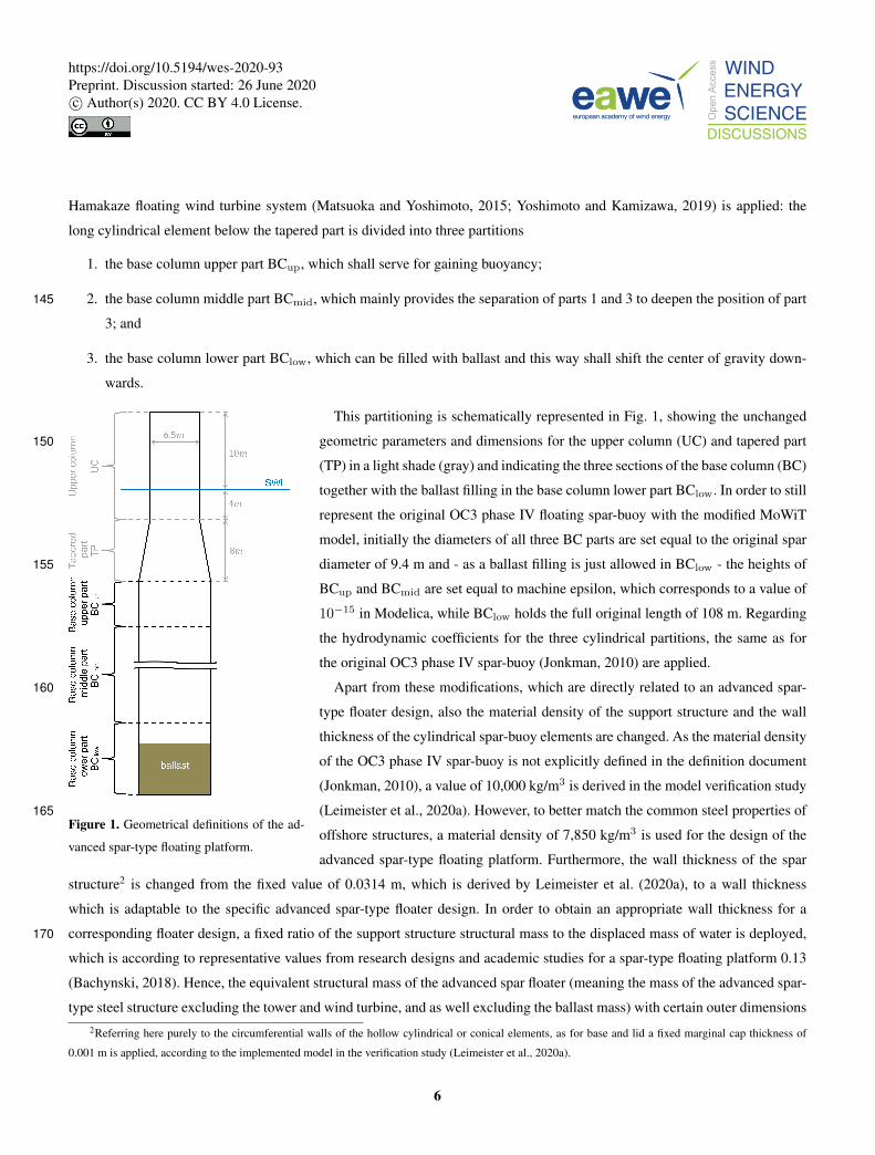
simulated time is checked against the specified simulation stop time (800 s according to Table 5). In case of an unsuccessful440
simulation and hence incomplete time series, the parameters of interest addressed in the constraints g15 to g17 for the system
performance are not taken by evaluating the time series but are set equal to twice the maximum allowable value, meaning
– max(total inclination angle)|failing system = 2 · 10.0◦ = 20.0◦
⇒ g15(system(X)|failed) = 20.0◦− 10.0◦ = 10.0◦ � 0
– max(horizontal nacelle acceleration)|failing system = 2 · 1.962 m/s2 = 3.924 m/s2445
⇒ g16(system(X)|failed) = 3.924 m/s2− 1.962 m/s2 = 1.962 m/s2 � 0
– mean translational motion|failing system = 2 · 64.0 m = 128 m
⇒ g17(system(X)|failed) = 128 m− 64.0 m = 64.0 m � 0
This way, it can be ensured that unsuccessful simulations do not comply with all constraints and hence are undesirable design
solutions, which the optimizer then discards from further selection of well-performing individuals.450
Having evaluated the simulated individuals of generation 0, the optimizer selects the design variables for the individuals of
the next generation (number 1), again in accordance with the specified allowable value ranges, but also based on the fitness
and constraints compliance rate of each of the previous individuals. Then, the loop of simulating the individuals, evaluating
each system with respect to the objective function and constraints, and re-selecting values (from the allowable value ranges)
for the design variables of the individuals of the next generation based on the performance of the individuals in the previous455
generation is repeated as long as the number of executed simulations is still below the specified total number of simulations of
10,000. This iterative optimization algorithm ends when the stop criterion is reached - the final results are now available.
5 Results
The optimization algorithm with the specified optimization settings is executed, however, the simulation run has to be inter-
rupted due to a required system restart. At that time already 8,133 individuals have been simulated. To complete the specified460
10,000 simulations without having any disruptive effects on the final results, the optimization is continued by providing the in-
dividuals of the last wholly simulated generation 133 as start population of the subsequent optimization execution, utilizing the
operator InjectedPopulation available in Platypus. Thus, the optimization run takes effectively about 31 days and eleven hours
and comprises 10,011 individuals simulated in total, ranging from generation 0 up to generation 166, with full populations up
to and including generation 165.465
5.1 Developments throughout the iterative optimization process
Figure 3 shows in light blue for all simulated individuals of the optimization run the values for the design variables x1 to x7,
as defined in Sect. 3.1. The values of the design variables of the reference advanced spar-type floating wind turbine system,
19
https://doi.org/10.5194/wes-2020-93Preprint. Discussion started: 26 June 2020c© Author(s) 2020. CC BY 4.0 License.

covered in Sect. 2.3, are plotted additionally as red lines for comparative purposes. Post-processing of the simulation results
and checking the constraints yield the dark blue recolored individuals which comply with all specified constraints. The finally470
selected optimum, which is presented in Sect. 5.3, is marked with a yellow filled circle framed in orange.
Figure 3. Development of the design variables throughout the iterative optimization process.
The developments of the design variables throughout the iterative optimization process show that in the first generations, the
optimizer selects individuals covering the entire design space; however, none of the first is meeting all requirements. With more
generations, the compliance rate is significantly increased, while it slightly decreases again when the focus of minimizing the
objective function is coming more to the fore again. Overall, the spread in the design variables is decreased for more generations475
being simulated and for some design variables the change in their values is even very limited for the individuals which comply
20
https://doi.org/10.5194/wes-2020-93Preprint. Discussion started: 26 June 2020c© Author(s) 2020. CC BY 4.0 License.

with all constraints. This indicates that the optimization algorithm is converging, though it has not yet fully converged, which
is underlined by the fact that the optimum originates from the last generation.
Similarly, the developments of the constraints g15 to g25 throughout the iterative optimization process are analyzed and
presented in Fig. 4. The first 14 constraints for the allowable value ranges of the design variables are excluded, as they are480
not constraints that are evaluated after the simulation, but are taken into account ahead of the simulations when the optimizer
selects the design variables for the new individuals, and hence are never violated. This can clearly be seen in Fig. 3, where all
Figure 4. Development of the constraints throughout the iterative optimization process.
21
https://doi.org/10.5194/wes-2020-93Preprint. Discussion started: 26 June 2020c© Author(s) 2020. CC BY 4.0 License.
individuals lie within the allowable value ranges of the design variables. In Fig. 4, the light cyan crosses indicate the results for
all simulated individuals, while the individuals which simultaneously comply with all constraints are recolored in dark bluish
green. The limits of the inequality constraints, which should all be less or equal to zero, are indicated in red and the finally485
selected optimum is marked again with a yellow filled circle framed in orange. For g21 and g22 it has to be noted that the
ordinate is limited to [-1E+4, 1E+4] for reasons of clarity, as a few more individuals yield values in the order of magnitude of
six.
For g18 to g20 and g23 to g25, which are directly related to and dependent on the design variables, the developments of
the constraints show a similar behavior as the developments of the corresponding design variables throughout the iterative490
optimization process. For the other constraints, the trend is rather different, having a large spread in the results throughout the
simulated generations. The fact that for g15 to g17 only a few distinguishable individuals are plotted in the first generations is
caused by the large number of unsuccessful simulations in the first trials of the optimizer, for which reason the performance
variables are set to the undesired values, as explained in Sect. 4.3.3, and hence are all the same for all failing systems. This is
as well visible throughout the generations, as there is a line at the specified undesired value formed by the individuals that do495
not complete the simulations successfully.
5.2 Advanced spar floater geometries in the design space
As presented and mentioned in Sect. 5.1, the individuals of the first generations cover the entire design space, specified through
the set allowable value ranges as prescribed by means of the constraints g1 to g14. The individuals that comply with all
constraints, however, are in a much more narrow area of the design space. The geometric design variables x1 to x6 of these500
individuals, setting height and diameter of each BC part in correlation, are plotted in light blue unfilled circles in Fig. 5. The
original and optimum designs are highlighted by red and blue, respectively, filled circles. From these individuals, which comply
with all constraints, seven examples are selected to demonstrate the diversity of potential (meaning successful but maybe
not yet optimum) advanced spar-type floater geometries. These examples are schematically drawn with black lines in Fig. 5
together with the original shape in red and having represented the ballast heights in dashed lines. The corresponding figures505
for design variables, performance parameters, objective function, and further resulting geometrical and structural parameters
of the presented examples are outlined in Table 6. These numbers also underline that - when evaluating g1 to g25 - none of the
inequality constraints is violated.
Looking at the floater geometries presented in Fig. 5, it becomes clear that not all of these shapes can be realized with
conventional structural solutions, where cylindrical sections are welded together. It has to be emphasized that these results are510
solely based on the hydrodynamic and system-level analyses, as specified within the optimization problem. Other additional
types of analyses - addressing structural integrity, manufacturability, and localized design - can, hence, deem some of the
presented potential design solutions unfeasible, which is discussed in some more detail in Sect. 6. However, the advantage
of this methodology by focusing only on the hydrodynamics is that a new range of potential floater designs is opened up and
shapes like these presented in Fig. 5 can still be considered as feasible solutions when different structural realization approaches515
are applied. These approaches can range from truss structures or tendons to realize large diameter changes as well as very thin
22
https://doi.org/10.5194/wes-2020-93Preprint. Discussion started: 26 June 2020c© Author(s) 2020. CC BY 4.0 License.

Figure 5. Exemplary potential advanced spar-type floater geometries selected from the individuals complying with all constraints.
elements without utilizing tapered sections or having issues with the structural integrity. Idea and impulse provider for such
different structural realization approaches can be for example innovative floating platform concepts such as the TetraSpar by
Stiesdal A/S (Stiesdal, 2019) or the pendulum-stabilized Hexafloat floater by Saipem and realized in the AFLOWT project
(Richard, 2019).520
23
https://doi.org/10.5194/wes-2020-93Preprint. Discussion started: 26 June 2020c© Author(s) 2020. CC BY 4.0 License.

Table 6. Key figures of the exemplary potential advanced spar-type floater geometries.
Ex. Gen. Ind.x1 x2 x3 x4 x5 x6 x7 Ballast density Wall thickness Draft
[m] [m] [m] [m] [m] [m] [m] [kg/m3] [m] [m]
1 115 45 0.116 13.410 16.612 6.930 0.002 25.903 4.573 4.585E+03 0.0578 44.836
2 14 15 8.899 1.528 31.100 5.551 1.183 19.518 17.774 1.003E+03 0.1052 38.252
3 78 32 15.253 0.164 16.612 0.018 1.109 25.033 10.709 2.156E+03 0.0580 38.160
4 8 6 14.755 0.172 20.090 6.970 4.665 91.993 84.016 1.037E+03 0.0797 115.628
5 9 45 10.550 43.919 33.605 13.896 1.798 89.776 84.684 1.008E+03 0.1344 117.470
6 10 8 5.158 2.331 34.015 6.997 46.270 25.683 22.727 1.022E+03 0.1135 90.950
7 9 57 0.523 2.331 33.154 6.159 62.944 25.683 22.727 1.013E+03 0.1106 106.786
Ex.Max(tot. inclination angle) Max(hor. nacelle acceleration) Mean(transl. motion) f1 Steel mass Ballast mass
[◦] [m/s2] [m] [m3] [kg] [kg]
1 9.9 1.337 28.155 99.1 7.778E+05 4.544E+06
2 5.0 1.231 22.241 266.2 2.090E+06 1.355E+07
3 9.3 1.724 27.308 107.7 8.455E+05 5.004E+06
4 2.6 1.955 17.503 530.1 4.162E+06 2.761E+07
5 1.6 1.664 21.089 1428.6 1.121E+07 7.570E+07
6 3.9 1.447 21.109 407.9 3.202E+06 2.111E+07
7 4.6 1.159 22.138 384.8 3.021E+06 1.987E+07
5.3 The optimized advanced spar-type floater
Due to the single-objective nature of the optimization problem, the selection of the optimum solution happens directly through
evaluating the one and only objective function. This means that from all individuals that comply with all constraints, this is
chosen as optimum which exhibits the lowest value for the structure material volume of its advanced spar-type floating platform
design.525
First, looking at the development of the objective function f1 throughout the iterative optimization process, as presented in
Fig. 6, the trend of all simulated individuals (plotted in light green) shows a significant minimization of the objective function
- clearly below the original value of 136.3 m3, indicated in Fig. 6 by a red line - after a large spread in the first generations.
Zooming into the objective function results from generation 40 on, as included in Fig. 6, provides a much clearer indication
of the development of the minimum structure material volume for the individuals which comply with all constraints (recolored530
in dark green): they aggregate to an asymptote. This is already visible in early generations; however, the spread in the objective
function results of the individuals complying with all constraints is decreasing with more generations being simulated. This
asymptotic clustering of the individuals which comply with all constraints to a minimum objective function value on the one
24
https://doi.org/10.5194/wes-2020-93Preprint. Discussion started: 26 June 2020c© Author(s) 2020. CC BY 4.0 License.

Figure 6. Development of the objective function throughout the iterative optimization process.
hand states the convergence of the iterative optimization process and on the other hand portends that there will be several -
more or less similar (elaborated in the following) - design solutions, which yield comparable low structure material volumes535
that are all very close to the minimum value observed.
The individual with the minimum structure material volume is pointed out in Fig. 6 by means of a yellow filled circle
framed in orange. This design solution yields a reduction of the structure material volume of more than 31% compared to the
original (modified) advanced spar-type floating platform. The fact that this optimum solution is just found in the last generation
simulated states that full convergence is not yet reached, despite the converging trend in most of the design variables and540
constraints, as well as in the objective function. Nevertheless, due to the asymptotic aggregation of the individuals mentioned
above, the first ten minimum objective function results from the individuals which comply with all constraints are evaluated.
This results - as some individuals yield the same objective function value - into 16 individuals with a just by 2.84E-4% increased
structure material volume, comparing the tenth lowest with the minimum value, and shapes that are difficult to distinguish from
each other. This proves the above mentioned anticipation that - due to the convergence of the iterative optimization process and545
the aggregation of the individuals’ objective function results to an asymptote - several very similar advanced spar-type floater
design solutions of comparable low structure material volumes are found.
The geometry of the optimized advanced spar-type floater shape (black line) is shown schematically in Fig. 7 in comparison
to the original floating platform drawn in red. The key figures of the optimized advanced spar-type floater geometry are
presented in Table 7. The found design solution is - as already mentioned - out of the last generation, indicating that the550
optimizer is still searching for individuals with lower structure material volume; however, the improvement within the last
25
https://doi.org/10.5194/wes-2020-93Preprint. Discussion started: 26 June 2020c© Author(s) 2020. CC BY 4.0 License.

simulated generations is negligible as outlined above. Both Fig. 7 and Table 7 indicate the following design development trend
within the iterative optimization process: to reduce the structure material volume
– the overall length of the floating platform is significantly decreased compared to the original geometry - the draft of the
advanced spar-type floater is, however, still significantly away from the minimum allowable draft of 15 m,555
– the width of the bottom part of the support structure is enlarged, while
– the upper and middle parts are almost left out, leading to this significant constriction in the tapered part, and
– a very low ballast volume is obtained through a significantly increased ballast density.
Figure 7. The optimized advanced spar-type floater geometry in
comparison with the original shape.
Table 7. Key figures of the optimized advanced spar-type floater.
Key figure Value
Generation 166
Individual 51
x1 0.115 m
x2 2.653 m
x3 16.525 m
x4 0.001 m
x5 3.0E-8 m
x6 24.761 m
x7 4.098 m
Ballast density 4.855E+03 kg/m3
Wall thickness 0.0571 m
Draft 36.762 m
Max(tot. inclination angle) 10.000◦
Max(hor. nacelle acceleration) 1.426 m/s2
Mean(transl. motion) 28.394 m
f1 93.9 m3
Steel mass 7.373E+05 kg
Ballast mass 4.267E+06 kg
The system performance - maximum total inclination angle, maximum horizontal nacelle acceleration, and mean transla-
tional motion - points out that the maximum total inclination angle is the most critical performance criterion, as the obtained560
value from the optimized design is equal to the specified upper limit of 10◦.
Overall, the shape of the optimized advanced spar-type floater design resembles rather a submerged thick barge-type floater,
hanging below the upper column element. This constriction in the tapered part is significant and would not directly be tech-
26
https://doi.org/10.5194/wes-2020-93Preprint. Discussion started: 26 June 2020c© Author(s) 2020. CC BY 4.0 License.

nically feasible, both from a manufacturing point of view and with respect to structural integrity. The reason for the current
shape obtained is the connection of the upper column to the upper BC part, which, however, is as well as the middle BC565
part negligible. Thus, the tapered part could directly connect the end of the upper column with the top of the lower BC part,
which is mainly purely the base column of the advanced spar-type floater. The change in required structure material would be
not that significant; however, the related change in the displaced water volume has to be taken into account by adjusting the
structure mass and by carefully evaluating the system performance due to the shifted center of buoyancy. This realization by
means of a tapered section, however, comes with a large diameter change and corresponding large taper angle, which may be570
critical for both hydrodynamic load calculations and manufacturing, as discussed in more detail in Sect. 6. However, the struc-
tural issues due to the geometrical configuration of the optimized floater as presented in Fig. 7, or as well as due to the large
diameter change when utilizing a tapered section, become void when eliminating the negligible upper and middle BC parts
and connecting the upper column and lower BC part by means of a number of rigid slender braces or some tendons instead
of a tapered segment. These manufacturing solutions go beyond the conventional structural realization approach of welding575
cylindrical sections together, but they make the found optimized floater design solution feasible and are expected to represent
similar system performance. The fitness of the floater solution proposed by the optimizer is underlined due to its similarity to
the most novel and alternative solutions suggested by the research community, such as the Stiesdal’s TetraSpar (Stiesdal, 2019)
or the Hexafloat by Saipem (Richard, 2019).
5.4 Performance of the optimized system in different environmental conditions580
With the design solution for the advanced spar-type floating offshore wind turbine platform obtained from the optimization
run, finally, the DLCs that are selected for the preprocessing automated system simulations for choosing the most critical DLC
(as presented in Sect. 4.1) are rerun to check whether a shift in the most critical DLC happens. The criticality is again assessed
by evaluating the fully-coupled system performance criteria (maximum total inclination angle, maximum horizontal nacelle
acceleration, and mean translational motion) and analyzing the corresponding constraints g15 to g17. The highest values and585
corresponding DLC simulation cases, as well as the values obtained with the selected DLC 1.6 at rated wind speed with wind
seed number 11 and yaw misalignment angle of 8◦, are presented in Table 8.
For the design solution from the optimization run, there is a shift in the criticality of the DLCs observed. The smallest change
in the order of criticality of the 54 environmental conditions happens in the horizontal nacelle acceleration. Still the cases from
DLC 1.6 at cut-out wind speed, as well as around rated wind speed, are most critical, but the DLC used within the iterative590
optimization algorithm is still among the first ten with an acceleration value that is almost 12% lower compared to the maximum
obtained from all simulated DLCs. This, however, is itself still more than 17% below the maximum allowable horizontal nacelle
acceleration and, hence, uncritical, which - on a side note - is not the case for the original floating spar-buoy wind turbine
system. A significant increase in the resulting performance values and considerable change in the order of criticality of the
environmental conditions is obtained for the mean translational motion. Here, the selected DLC for the optimization process595
drops down from the originally sixth position to the 22nd, while it is just 10% below the highest value achieved, which is still
less than half of the maximum allowable value and, hence, again uncritical. However, the most sever shift in the criticality
27
https://doi.org/10.5194/wes-2020-93Preprint. Discussion started: 26 June 2020c© Author(s) 2020. CC BY 4.0 License.

Table 8. The highest values for the three performance parameters and corresponding DLC simulation case, based on the optimized advanced
spar-type floating system.
Position DLC Wind speed Wind seed Yaw misalignment Max(total inclination angle)
1 1.1 13.0 m/s 18 8◦ 12.061◦
2 1.1 11.4 m/s 10 0◦ 12.011◦
3 1.3 11.4 m/s 10 0◦ 12.011◦
4 1.1 11.4 m/s 7 -8◦ 11.903◦
5 1.3 11.4 m/s 7 -8◦ 11.903◦
30 1.6 11.4 m/s 11 8◦ 10.000◦
Position DLC Wind speed Wind seed Yaw misalignment Max(horizontal nacelle acceleration)
1 1.6 25.0 m/s 17 8◦ 1.620 m/s2
2 1.6 25.0 m/s 18 8◦ 1.618 m/s2
3 1.6 25.0 m/s 13 -8◦ 1.550 m/s2
4 1.6 25.0 m/s 16 0◦ 1.521 m/s2
5 1.6 25.0 m/s 15 0◦ 1.480 m/s2
10 1.6 11.4 m/s 11 8◦ 1.426 m/s2
Position DLC Wind speed Wind seed Yaw misalignment Mean(translational motion)
1 1.1 13.0 m/s 15 0◦ 31.564 m
2 1.1 11.4 m/s 9 0◦ 31.375 m
3 1.3 11.4 m/s 9 0◦ 31.375 m
4 1.1 13.0 m/s 17 8◦ 30.631 m
5 1.1 11.4 m/s 12 8◦ 30.337 m
22 1.6 11.4 m/s 11 8◦ 28.394 m
of the DLCs happens for the total inclination angle of the system. As indicated in Sect. 5.3, the maximum allowable value
is already reached in the environmental condition considered for the optimization approach. This DLC, however, is for the
obtained optimized design solution no longer prevailing but just on the 30th position, meaning that 29 other environmental600
conditions (mostly from DLC 1.1 and DLC 1.3, as well as some others from DLC 1.6) exceed the specified upper limit by up
to more than 20%. In these environmental conditions, the floater designs obtained from the optimization run would have to
stop operation, while the overall system stability is not expected to be critical, as commonly much higher values for a parked
floating wind turbine system in extreme environmental states are acceptable, such as 15◦ considered by Hegseth et al. (2020).
However, to avoid reduced system availability, the occurring changed criticality of the DLCs has to be addressed already during605
28
https://doi.org/10.5194/wes-2020-93Preprint. Discussion started: 26 June 2020c© Author(s) 2020. CC BY 4.0 License.

the optimization - by for example considering safety factors for such critical and design-driving performance criteria - and the
performance in all environmental conditions can be further improved by subsequent optimization of the currently unaltered
mooring system. These options are discussed in more detail in Sect. 6.
6 Discussion
In addition to the presented, analyzed, and discussed results in Sect. 5, these are addressed in more detail and further aspects610
are discussed in the following.
Based on the results and findings from the DLC simulations with the optimized advanced spar-type floating wind turbine
system design, it is recommended to take some safety factors for the maximum allowable performance values into account. If
the horizontal nacelle acceleration would have been exceeded in some of the 54 environmental conditions, it would not have
been that critical, as a maximum allowable value of up to 0.3 times the gravitational acceleration constant - and not only 0.2615
times as applied - is often accepted, as already mentioned in Sect. 2.4. The specific maximum allowable values for an operating
floating offshore wind turbine system have to be provided by the turbine manufacturer or operator. Thus, maybe a higher
inclination angle is still acceptable; however, if 10◦ are really the uppermost tolerated angle, a value of 8◦ or maximum 9◦
shall be used for the optimization constraint. A reduced maximum allowable total inclination angle can as well afterwards be
applied in the post-processing of the results and this way an in all 54 environmental conditions well-performing floater design620
can be obtained, with the downside that a larger structure material volume is required and that this design does not represent an
optimized solution. A profitable option, hence, is to adjust the - currently excluded and unchanged - mooring system properties
and layout design. By modifying these in a subsequent optimization task, the optimized floater design can be retained and at the
same time the performance of the floating offshore wind turbine system in all considered environmental conditions improved -
in this case especially the system inclination.625
Considering the wide design space - especially the broad allowable value ranges for the structural diameters - and the extreme
environmental conditions, included in the DLC simulations, some refinements in the model with respect to the hydrodynamic
calculations are suggested:
– For an accurate representation of the hydrodynamic loads on the floating structure, the hydrodynamic coefficients have
to be recalculated for each specific diameter. While the horizontal added mass coefficient, as well as the total inertia630
force are already determined in dependency of the actual structural diameter and wave number, as the MacCamy-Fuchs
approach is applied for each column element separately, the horizontal drag coefficient is currently not altered from
the original value 0.6. This is a valid assumption for large diameters already at low flow velocities; however, for small
diameter structures, which can occur within the optimization algorithm, an around twice as large horizontal drag coeffi-
cient might be applicable (Clauss et al., 1992). In the vertical (heave) direction, both added-mass and drag coefficients635
are currently unchanged, while a vertical Froude-Krylov excitation force is considered, accounting for the difference
between UC diameter and the diameter at the floater base. Especially for geometries with large diameter changes, as
well as with large diameters, which can be regarded as heave plates, the hydrodynamic coefficients will differ from
29
https://doi.org/10.5194/wes-2020-93Preprint. Discussion started: 26 June 2020c© Author(s) 2020. CC BY 4.0 License.

the original values for a continuous cylinder as the OC3 phase IV spar-buoy. Furthermore, the vertical Froude-Krylov
excitation force would have to be adjusted to the specific geometry, when the lower BC part is connected by means640
of trusses or tendons to the upper column, to account for the differences between each upper and lower surfaces. This
both - changes in the hydrodynamic coefficients in heave direction and adjusted vertical Froude-Krylov excitation force
- will mainly affect the heave motion of the floating system, as well as the roll and pitch motions in some respect. With
the geometry obtained from the optimization, however, it is expected to experience less strong system responses if the
hydrodynamic coefficients are adjusted accordingly - which would benefit for example the system inclination - while645
the system responses will increase slightly if the vertical Froude-Krylov excitation force is determined accurately for the
considered geometry.
– For more extreme environmental conditions with extreme waves and similar structures as obtained with the optimization
run, which tend to have a large diameter directly at or close to the top of the BC, the event that the upper surface of
such a large diameter cylinder becomes dry has to be accounted for when calculating the added mass and damping650
coefficients in order to not overestimate the heave and pitch added mass and, thus, to not underestimate the horizontal
nacelle acceleration in case of more energetic sea states. Furthermore, having a horizontal surface close to the water
surface - in the presented settings with a minimum distance of 12 m - could be as well critical structurally or maybe
due to the impossibility of common service vessels to approach the wind turbine. However, it has to be noted that it is
aimed to establish a floating platform optimized with respect to the hydrodynamics. This, then, needs to be compromised655
imposing other prevailing constraints, such as structural limits - as discussed later in more detail again - or accessibility,
for which for example walk-to-work solutions with a gangway can be exploited.
– The applied MacCamy-Fuchs approach is in principle just valid for cylinders with vertical walls and not for cylinders
with abrupt changes of diameters, leading to conical sections or even large horizontal surfaces anywhere along the
column (the latter one, however, is considered again by means of the vertical Froude-Krylov excitation force, as discussed660
previously). If the MacCamy-Fuchs approach is applied to conical structures, the wave load from especially waves
with low periods will be underestimated. This could be in the order of magnitude of up to 8% or 14% for a cone
angle of around 6.7◦ or 12.2◦, respectively, and could affect wave periods of 3 s to 6 s or 3.5 s to 7 s, according to
investigations on a tapered bottom-fixed offshore wind turbine support structure (Leimeister et al., 2019). Thus, this
potential underestimation of the hydrodynamic loading is mostly relevant for the environmental conditions of DLC 1.1,665
as well as for the below and at rated wind speed cases of DLC 1.3. For the design solution proposed in Sect. 5.3, in which
the bottom end of the upper column is directly connected with the large diameter lower BC part, the taper angle would
amount 32◦. Any hydrodynamic calculations based on the MacCamy-Fuchs approach would no longer be meaningful if
the design solution is realized by means of a solid tapered part. Thus, the alternative suggestion of having a number of
rigid slender braces instead would be favored. In order to ensure valid computation of the hydrodynamics already within670
the optimization approach, another constraint on the maximum taper angle shall be added, as implemented with a limit
30
https://doi.org/10.5194/wes-2020-93Preprint. Discussion started: 26 June 2020c© Author(s) 2020. CC BY 4.0 License.

of 10◦ by Hegseth et al. (2020). This aspect is, however, less critical when allowing for different structural solutions,
where trusses or tendons prevent any utilization of strongly tapered sections.
As addressed and discussed in Sects. 5.2 and 5.3, the geometrical configuration of the potential and optimized advanced spar-
type floaters as presented in Figs. 5 and 7 may not be technically feasible from a structural integrity and manufacturability point675
of view, adopting the standard manufacturing solutions. For obtaining a high detail structural design, further localized analyses
and assessments regarding the manufacturability have to be performed subsequently. However, structural integrity checks for
buckling or stress concentration and for accounting for a realistic and adjustable base and lid thickness, which is currently just
set to a fixed marginal value, can as well directly be integrated in the definition of the optimization problem. Nonetheless, based
on the assumptions and focus of this study, which is on hydrodynamic and system-level analyses, a significantly improved and680
more cost-efficient floater can be achieved. This is as well feasible when considering different structural realization approaches,
such as braces and truss structures, or tendons as utilized in innovative floater concepts (Richard, 2019; Stiesdal, 2019), instead
of following purely the conventional structural approach of welding cylindrical and tapered sections together.
Finally and admittedly, for really considering an optimization of the wind turbine system cost, the ratio of CapEx (Capital
Expenditure) to AEP (Annual Energy Production) or even the LCoE, which additionally takes OpEx (Operational Expenditure)685
- and sometimes also costs of decommissioning - into account, would have to be considered to be minimized. This way, a
real trade-off between saved material costs, changed expenditure of manufacturing and maintaining the system, and different
system performance, and hence affected AEP can be found. However, this requires a more holistic and complex approach,
considering annual environmental distributions at the location of interest, calculations for the full life-time of the system, as
well as knowledge of possible manufacturing processes and related costs. The present work can be further expanded in the690
future to take into account these steps and aspects.
7 Conclusions
In this paper, an automated optimization approach is applied to a floating offshore wind turbine system in order to design
an advanced spar-type floating platform, which is optimized with respect to the change in hydrodynamics and their impact
on the main system performance, while structural, manufacturability, or other constraints are not considered. This approach695
is taken in order to be able to explore novel design spaces which can be better from an hydrodynamic point of view, but
that may require novel structural solutions approaches, as actively investigated by the community (e.g. Stiesdal’s TetraSpar
and Saipem’s Hexafloat). The application is based on the OC3 phase IV spar-buoy floating offshore wind turbine system.
This, however, is modified by dividing the spar-buoy base column into three distinct partitions, so that sufficient buoyancy,
as well as a deep center of gravity can be obtained. Furthermore, the wall thickness is adjusted based on a common ratio of700
the support structure’s structural mass to the displaced mass of water. The optimization focuses on the minimization of the
steel volume of the floater, which represents an approximation of the CapEx of the support platform. In addition, constraints
regarding the outer dimensions (meaning the allowable value ranges of the design variables), the global fully-coupled system
performance, the system draft, the ballast, and the geometric integrity are defined. Having selected, based on preprocessing
31
https://doi.org/10.5194/wes-2020-93Preprint. Discussion started: 26 June 2020c© Author(s) 2020. CC BY 4.0 License.

automated system simulations, one DLC which is most critical for the constrained system performance criteria, the iterative705
optimization algorithm run is performed, utilizing the Python-Modelica framework for automated simulation and optimization,
as well as using the genetic algorithm NSGAII as optimizer. The analysis of the optimization simulation results shows that the
individuals which comply with all prescribed constraints aggregate as for their objective function values to an asymptote. The
results from the optimization run emphasize the complexity of the optimization problem and indicate that - despite the large
number of simulations and the asymptotic clustering to a minimum objective function - full convergence is not yet obtained.710
Nevertheless, the applied iterative optimization algorithm presented in this study yields an advanced spar-type floating support
structure design, which
– has a by more than 31% reduced structure material volume compared to the original floating platform,
– meets all global performance criteria for the considered critical DLC,
– has an overall draft of 36.8 m,715
– utilizes MagnaDense or high density concrete as ballast material, and
– resembles a submerged thick barge-type floater.
The operability is - taking the maximum allowable system performance values as strict obligation for operating ability -
limited to 46.3% of the considered 54 environmental conditions. This, however, can be much more extended when modifying
subsequently the currently unchanged mooring system properties and layout. Based on the applied hydrodynamic and system-720
level analyses an optimized initial advanced spar-type floater design is obtained, which has to be further refined by incorporating
structural checks into the optimization process, but can be realized by means of innovative structural approaches, which utilize
trusses or tendons instead of solely welding cylindrical sections together.
Author contributions. ML: Conceptualization, Data curation, Methodology, Software, Validation, Formal analysis, Investigation, Project
administration, Visualization, Writing - original draft, Writing - review; MC: Conceptualization, Methodology, Supervision, Writing - review725
& editing; AK: Supervision, Writing - review & editing, Funding acquisition.
Competing interests. The authors declare that they have no conflict of interest.
Acknowledgements. This work was partially supported by grant EP/L016303/1 for Cranfield University, University of Oxford and University
of Strathclyde, Centre for Doctoral Training in Renewable Energy Marine Structures - REMS (http://www.remscdt.ac.uk/) from the UK
Engineering and Physical Sciences Research Council (EPSRC) and the German Fraunhofer Institute for Wind Energy Systems (Fraunhofer730
IWES).
32
https://doi.org/10.5194/wes-2020-93Preprint. Discussion started: 26 June 2020c© Author(s) 2020. CC BY 4.0 License.

References
Bachynski, E. E.: Fixed and Floating Offshore Wind Turbine Support Structures, in: Offshore Wind Energy Technology, edited by Anaya-
Lara, O., Tande, J. O., Uhlen, K., and Merz, K., pp. 103–142, Wiley, Hoboken, NJ, https://doi.org/10.1002/9781119097808.ch4, 2018.
Bachynski, E. E. and Moan, T.: Design considerations for tension leg platform wind turbines, Marine Structures, 29, 89–114,735
https://doi.org/10.1016/j.marstruc.2012.09.001, 2012.
Bachynski, E. E., Etemaddar, M., Kvittem, M. I., Luan, C., and Moan, T.: Dynamic Analysis of Floating Wind Turbines During Pitch
Actuator Fault, Grid Loss, and Shutdown, Energy Procedia, 35, 210–222, https://doi.org/10.1016/j.egypro.2013.07.174, 2013.
Butcher, N.: The Steel Tariff and Construction Cost: Putting It Into Context, Archinect, News, https://archinect.com/news/article/150058852/
the-steel-tariff-and-construction-cost-putting-it-into-context, 2018.740
Butterfield, S., Musial, W., Jonkman, J., and Sclavounos, P.: Engineering Challenges for Floating Offshore Wind Turbines: Conference Paper
NREL/CP-500-38776, Proceedings of the European Offshore Wind Conference 2005, 26-28 October, Copenhagen, Denmark, 2007.
Clauss, G., Lehmann, E., and Östergaard, C.: Offshore Structures: Volume I: Conceptual Design and Hydromechanics, Springer London,
London, https://doi.org/10.1007/978-1-4471-3193-9, 1992.
DNV GL AS: Loads and site conditions for wind turbines, vol. DNVGL-ST-0437, DNV GL AS, november 2016 edn., 2016.745
DNV GL AS: Floating wind turbine structures, vol. DNVGL-ST-0119, DNV GL AS, july 2018 edn., 2018.
European Wind Energy Association: Deep Water: The next step for offshore wind energy, EWEA, Brussels, Belgium, www.ewea.org/report/
deep-water, 2013.
Future Power Technology: Floating foundations are the future of deeper offshore wind, Future Power Technology, Comment, 2019.
Grogan, T.: Steel, Aluminum Tariffs Will Hit Prices Hard Through Year End, Engineering News-Record, https://www.enr.com/articles/750
44200-steel-aluminum-tariffs-will-hit-prices-hard-through-year-end?v=preview, 2018.
Hegseth, J. M., Bachynski, E. E., and Martins, J. R.: Integrated design optimization of spar floating wind turbines, Marine Structures, 72,
102 771, https://doi.org/10.1016/j.marstruc.2020.102771, 2020.
Hirai, T., Sou, A., and Nihei, Y.: Wave Load Acting on Advanced Spar in Regular Waves, in: Proceedings of the ASME 37th In-
ternational Conference on Ocean, Offshore and Arctic Engineering, American Society of Mechanical Engineers, New York, N.Y.,755
https://doi.org/10.1115/OMAE2018-77821, 2018.
Huijs, F., Mikx, J., Savenije, F., and de Ridder, E.-J.: Integrated design of floater, mooring and control system for a semi-submersible floating
wind turbine, in: Proceedings of the EWEA Offshore, 2013.
International Electrotechnical Commission: Wind energy generation systems - Part 3-1: Design requirements for fixed offshore wind turbines,
vol. IEC 61400-3-1:2019-04(en), International Electrotechnical Commission, Geneva, 1.0 edn., 2019a.760
International Electrotechnical Commission: Wind energy generation systems - Part 3-2: Design requirements for floating offshore wind
turbines, vol. IEC TS 61400-3-2:2019-04(en), International Electrotechnical Commission, Geneva, 1.0 edn., 2019b.
James, R. and Ros, M. C.: Floating Offshore Wind: Market and Technology Review, Carbon Trust, UK, 2015.
Jonkman, J.: Definition of the Floating System for Phase IV of OC3, NREL/TP-500-47535, National Renewable Energy Laboratory, Golden,
Colorado, https://doi.org/10.2172/979456, 2010.765
Jonkman, J., Butterfield, S., Musial, W., and Scott, G.: Definition of a 5-MW Reference Wind Turbine for Offshore System Development,
NREL/TP-500-38060, National Renewable Energy Laboratory, Golden, Colorado, https://doi.org/10.2172/947422, 2009.
Katsouris, G. and Marina, A.: Cost Modelling of Floating Wind Farms, ECN-E-15-078, 2016.
33
https://doi.org/10.5194/wes-2020-93Preprint. Discussion started: 26 June 2020c© Author(s) 2020. CC BY 4.0 License.

Kolios, A., Borg, M., and Hanak, D.: Reliability analysis of complex limit states of floating wind turbines, Journal of Energy Challenges and
Mechanics, 2, 6–9, 2015.770
Krieger, A., Ramachandran, G. K. V., Vita, L., Alonso, P. G., Almería, G. G., Berque, J., and Aguirre, G.: Deliverable D7.2 Design Basis:
LIFES50+, 2015.
Lee, K. H.: Responses of floating wind turbines to wind and wave excitation, Master thesis, Massachusetts Institute of Technology, http:
//hdl.handle.net/1721.1/33564, 2005.
Leimeister, M.: Python-Modelica Framework for Automated Simulation and Optimization, in: Proceedings of the 13th Interna-775
tional Modelica Conference, Linköping Electronic Conference Proceedings, pp. 51–58, Linköping University Electronic Press,
https://doi.org/10.3384/ecp1915751, 2019.
Leimeister, M. and Thomas, P.: The OneWind Modelica Library for Floating Offshore Wind Turbine Simulations with Flexible Structures,
in: Proceedings of the 12th International Modelica Conference, Linköping Electronic Conference Proceedings, pp. 633–642, Linköping
University Electronic Press, https://doi.org/10.3384/ecp17132633, 2017.780
Leimeister, M., Kolios, A., and Collu, M.: Critical review of floating support structures for offshore wind farm deployment, Journal of
Physics: Conference Series, 1104, 012 007, https://doi.org/10.1088/1742-6596/1104/1/012007, 2018.
Leimeister, M., Spill, S., Dose, B., Foglia, A., Siegl, K., Karch, M., Heins, E., Schümann, B., Dührkop, J., and Hartmann, H.: TANDEM
- Towards an Advanced Design of Large Monopiles: Schlussbericht, Technische Informationsbibliothek (TIB), Hannover, Germany,
https://doi.org/10.2314/KXP:1678117404, 2019.785
Leimeister, M., Kolios, A., and Collu, M.: Development and Verification of an Aero-Hydro-Servo-Elastic Coupled Model of Dynamics for
FOWT, Based on the MoWiT Library, Energies, 13, 1974, https://doi.org/10.3390/en13081974, 2020a.
Leimeister, M., Kolios, A., Collu, M., and Thomas, P.: Development of a framework for wind turbine design and optimization: (to be
published), Engineering Science and Technology, an International Journal, 2020b.
Leimeister, M., Kolios, A., Collu, M., and Thomas, P.: Design optimization of the OC3 phase IV floating spar-buoy, based on global limit790
states, Ocean Engineering, 202, 107 186, https://doi.org/10.1016/j.oceaneng.2020.107186, 2020c.
LKAB Minerals: Non-hazardous material safety data sheet for MagnaDense, https://www.lkabminerals.com/wp-content/uploads/2019/02/
MagnaDense-SDS-12-06INT-19-03.pdf, 2019.
Löfken, J. O.: Das nächste große Ding auf See, Neue Energie, pp. 34–37, 2019.
Main(e) International Consulting LLC: Floating Offshore Wind Foundations: Industry Consortia and Projects in the United States, Europe795
and Japan: An Overview, 2013.
Mast, E., Rawlinson, R., and Sixtensson, C.: TKI Wind op Zee: Potential of floating offshore wind: Market study floating wind in the
Netherlands, RVO (Netherlands Enterprise Agency), 2015.
Matha, D., Sandner, F., and Schlipf, D.: Efficient critical design load case identification for floating offshore wind turbines with a reduced
nonlinear model, Journal of Physics: Conference Series, 555, 012 069, https://doi.org/10.1088/1742-6596/555/1/012069, 2014.800
Matsuoka, R. and Yoshimoto, H.: Verification of Precision Concerning the Design of Advanced Spar Type Structure, Conference Proceedings
The Japan Society of Naval Architects and Ocean Engineers, 20, 2015S–OS1–1, 2015.
Nejad, A. R., Bachynski, E. E., and Moan, T.: On Tower Top Axial Acceleration and Drivetrain Responses in a Spar-Type Floating Wind
Turbine, in: Proceedings of the ASME 36th International Conference on Ocean, Offshore and Arctic Engineering, American Society of
Mechanical Engineers, New York, N.Y., https://doi.org/10.1115/OMAE2017-62314, 2017.805
34
https://doi.org/10.5194/wes-2020-93Preprint. Discussion started: 26 June 2020c© Author(s) 2020. CC BY 4.0 License.

Ng, C. and Ran, L., eds.: Offshore wind farms: Technologies, design and operation, vol. number 92 of Woodhead Publishing series in energy,
Elsevier WP Woodhead Publishing, Amsterdam and Boston and Cambridge and Heidelberg and London and New York and Oxford and
Paris and San Diego and San Francisco, 2016.
Quest Floating Wind Energy: The Definitive Guide to Floating Wind Concepts, Quest Floating Wind Energy, 2020.
Richard, C.: Funds for Ireland’s first floating demonstrator, Windpower Monthly, https://www.windpowermonthly.com/article/1579762/810
funds-irelands-first-floating-demonstrator, 2019.
Robertson, A., Jonkman, J., Masciola, M., Song, H., Goupee, A., Coulling, A., and Luan, C.: Definition of the Semisubmersible Floating
System for Phase II of OC4, NREL/TP-5000-60601, National Renewable Energy Laboratory, Golden, Colorado, 2014.
Stiesdal, H.: TetraSpar and TetraBase: Industrialized Offshore Wind Turbine Foundations, https://www.stiesdal.com/material/2019/02/
Stiesdal-Tetra-01.02.19.pdf, 2019.815
Strobel, M., Vorpahl, F., Hillmann, C., Gu, X., Zuga, A., and Wihlfahrt, U.: The OnWind Modelica Library for OffshoreWind Turbines
- Implementation and first results, in: Proceedings from the 8th International Modelica Conference, Linköping Electronic Conference
Proceedings, pp. 603–609, Linköping University Electronic Press, https://doi.org/10.3384/ecp11063603, 2011.
Suzuki, K., Yamaguchi, H., Akase, M., Imakita, A., Ishihara, T., Fukumoto, Y., and Oyama, T.: Initial Design of Tension Leg Platform for
Offshore Wind Farm, Journal of Fluid Science and Technology, 6, 372–381, https://doi.org/10.1299/jfst.6.372, 2011.820
Thomas, P., Gu, X., Samlaus, R., Hillmann, C., and Wihlfahrt, U.: The OneWind Modelica Library for Wind Turbine Simulation with Flexible
Structure - Modal Reduction Method in Modelica, in: Proceedings of the 10th International Modelica Conference, Linköping Electronic
Conference Proceedings, pp. 939–948, Linköping University Electronic Press, https://doi.org/10.3384/ECP14096939, 2014.
WindEurope: Floating Offshore Wind Vision Statement, vol. June 2017, WindEurope, Brussels, Belgium, 2017.
Wright, C., Yoshimoto, H., Wada, R., and Takagi, K.: Numerical Modelling of a Relatively Small Floating Body’s Wave and Low Frequency825
Motion Response, Compared With Observational Data, in: Proceedings of the ASME 38th International Conference on Ocean, Offshore
and Arctic Engineering, American Society of Mechanical Engineers, https://doi.org/10.1115/OMAE2019-96443, 2019.
Yamanaka, S., Hirai, T., Nihei, Y., and Sou, A.: Interaction Between Advanced Spar and Regular Waves, in: Proceedings of the ASME
36th International Conference on Ocean, Offshore and Arctic Engineering, American Society of Mechanical Engineers, New York, N.Y.,
https://doi.org/10.1115/OMAE2017-61788, 2017.830
Yoshimoto, H. and Kamizawa, K.: Validation of the Motion Analysis Method of Floating Offshore Wind Turbines Using Observation Data
Acquired by Full Scale Demonstration Project, in: Proceedings of the ASME 38th International Conference on Ocean, Offshore and Arctic
Engineering, American Society of Mechanical Engineers, https://doi.org/10.1115/OMAE2019-95828, 2019.
Yoshimoto, H., Yoshida, H., and Kamizawa, K.: Validation of Applicability of Low Frequency Motion Analysis Theory Using Observa-
tion Data of Floating Offshore Substation, in: Proceedings of the ASME 37th International Conference on Ocean, Offshore and Arctic835
Engineering, American Society of Mechanical Engineers, New York, N.Y., https://doi.org/10.1115/OMAE2018-77201, 2018.
Zhu, H., Sueyoshi, M., Hu, C., and Yoshida, S.: A study on a floating type shrouded wind turbine: Design, modeling and analysis, Renewable
Energy, 134, 1099–1113, https://doi.org/10.1016/j.renene.2018.09.028, 2019.
35
https://doi.org/10.5194/wes-2020-93Preprint. Discussion started: 26 June 2020c© Author(s) 2020. CC BY 4.0 License.