Embed Size (px)
Citation preview
Cadence Payne1
Mentors: Ganesh Rajapopalan2, Chris Eckert2, Berhanu Bulcha2
Morehead State University1
MIT Haystack Observatory2
A Fully Automated Scanning RFI Monitoring System for VGOS Site Surveys
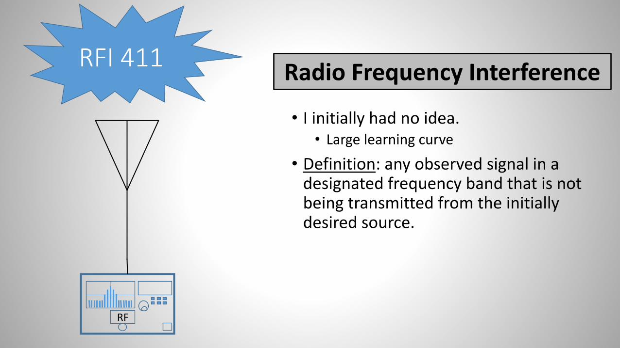
RFI 411
• I initially had no idea.• Large learning curve
• Definition: any observed signal in a designated frequency band that is not being transmitted from the initially desired source.
RF
Radio Frequency Interference
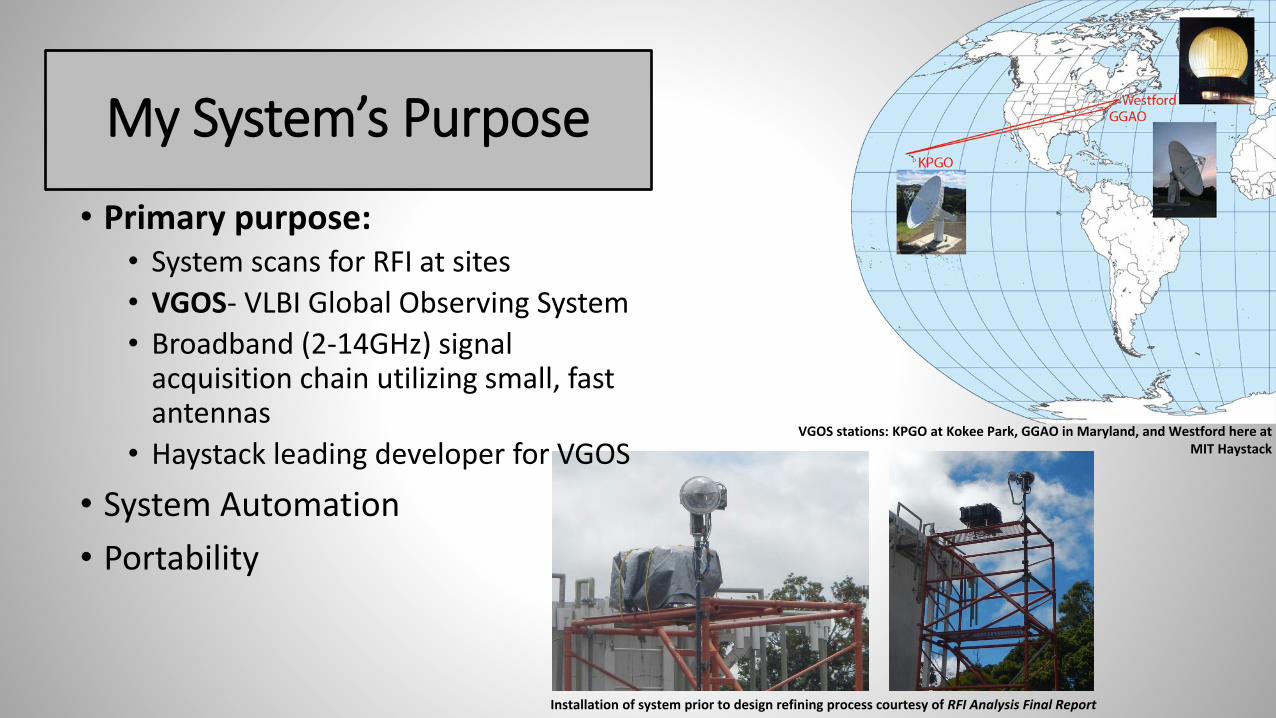
My System’s Purpose
• Primary purpose:• System scans for RFI at sites
• VGOS- VLBI Global Observing System
• Broadband (2-14GHz) signal acquisition chain utilizing small, fast antennas
• Haystack leading developer for VGOS
• System Automation
• Portability
Installation of system prior to design refining process courtesy of RFI Analysis Final Report
VGOS stations: KPGO at Kokee Park, GGAO in Maryland, and Westford here at MIT Haystack

How does it all work?
• System Layout
• Motional capabilities
• Data acquisition instrumentation
• Underlying software
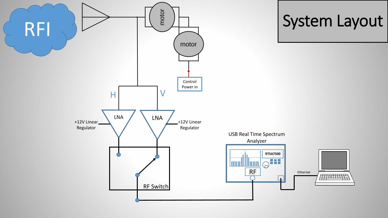
Control Power in
RTSA7500
RF Ethernet
RFI moto
r
H V
LNA LNA
motor
+12V Linear Regulator
+12V Linear Regulator
RF Switch
System Layout
USB Real Time Spectrum Analyzer
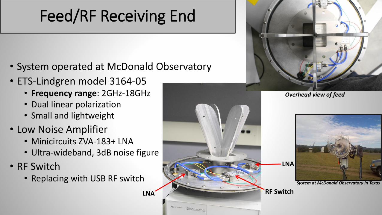
Feed/RF Receiving End
• System operated at McDonald Observatory
• ETS-Lindgren model 3164-05• Frequency range: 2GHz-18GHz• Dual linear polarization• Small and lightweight
• Low Noise Amplifier • Minicircuits ZVA-183+ LNA• Ultra-wideband, 3dB noise figure
• RF Switch• Replacing with USB RF switch
Overhead view of feed
LNA
LNA
RF Switch
System at McDonald Observatory in Texas

Motional Instrumentation
• Class 5 IP65 Rated M-style SmartMotor• Functions in harsh/wet weather• Ideal operating temperature range: 0°C - 85°C• Small size• Two modes of functionality: relative and absolute position moves
or velocity moves• SMI Software (SmartMotor Interface)
• Bill of Materials (BOM) Experience• ICD (Interface Control Document)• Parts list
• Mounting plan• 2 motors required
Image courtesy of Manufacturer’s specs

360° azimuthal rotation
90° elevational rotation
Feed facing head on.
Zeroed out at this position using limit switches.
SmartMotorMounting Layout
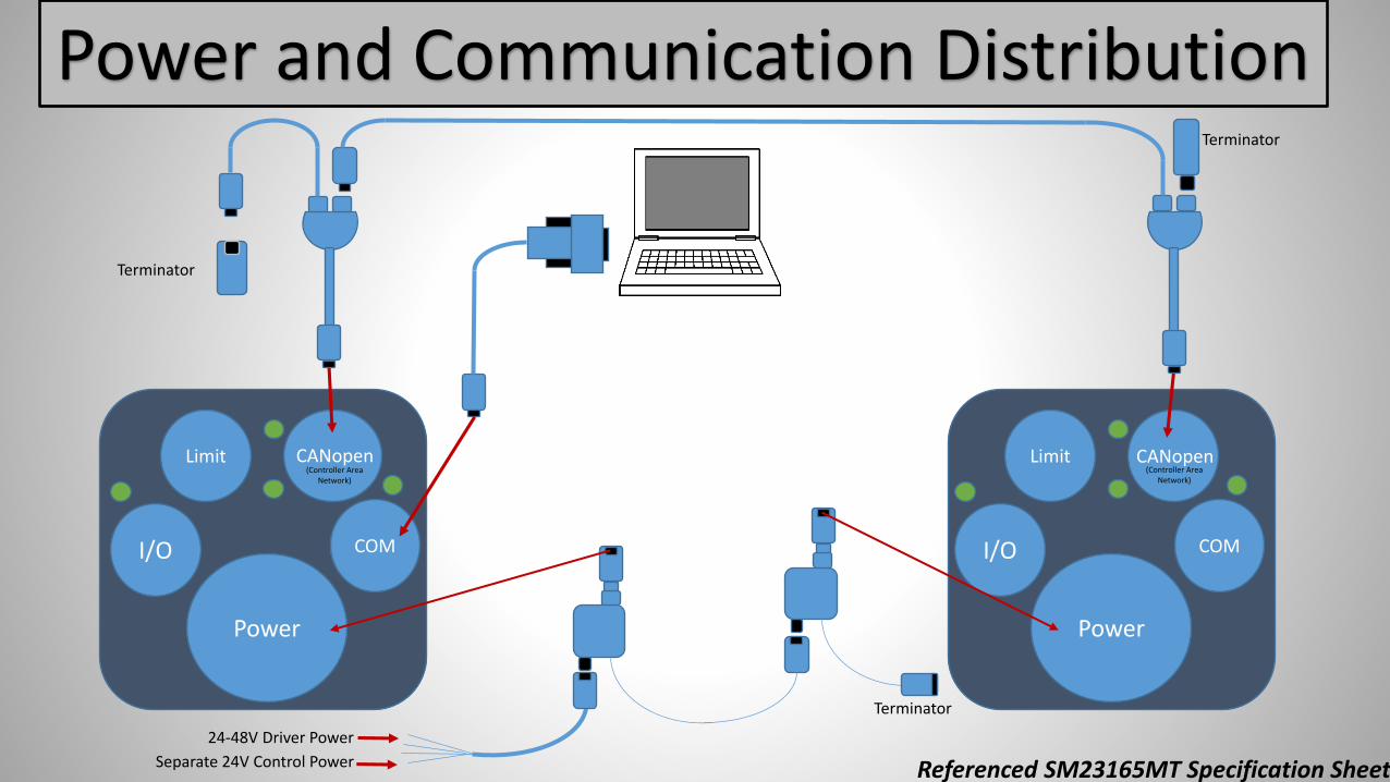
Power and Communication Distribution
Power
I/O
Limit
COM
Power
I/O
Limit
COM
CANopen CANopen
Terminator
Terminator
24-48V Driver Power
Separate 24V Control Power
Terminator
Referenced SM23165MT Specification Sheet
(Controller Area Network)
(Controller Area Network)

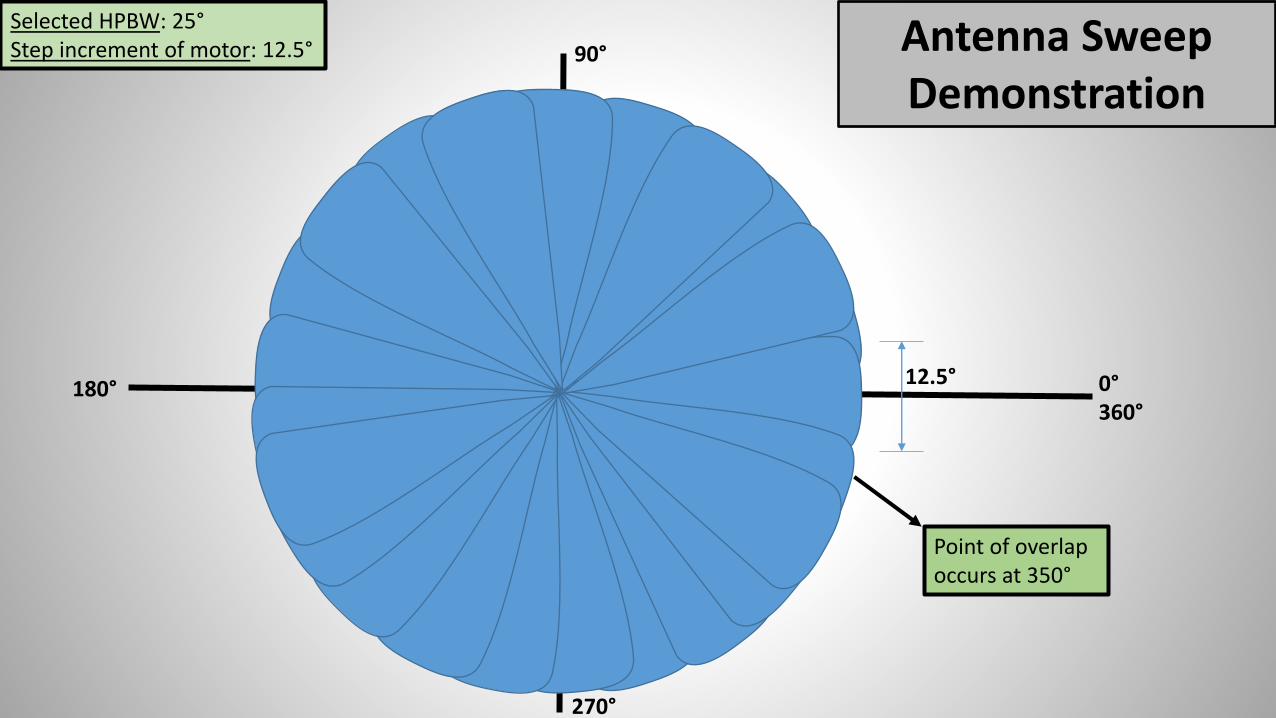
Determining Increments of Motion
• Beam patterns• 3dB Half-Power Beamwidth with line of best fit
• E-plane
• H-plane
• 25° HPBW selected• Motor steps in increments of 12.5°
Image courtesy of manufacturer specs.
The step increments that the motor will be programmed to implement.
90°
0°360°
180°
270°
Selected HPBW: 25°Step increment of motor: 12.5°
12.5°
Point of overlap occurs at 350°
Antenna Sweep Demonstration

Evolution of Spectrum Analyzers
• Out with the old, in with the new
Not spectrum analyzer
BB60C—SignalHoundRTSA7500—Berkeley
NucleonicsMXA—AgilentHewlett Packard 8563A
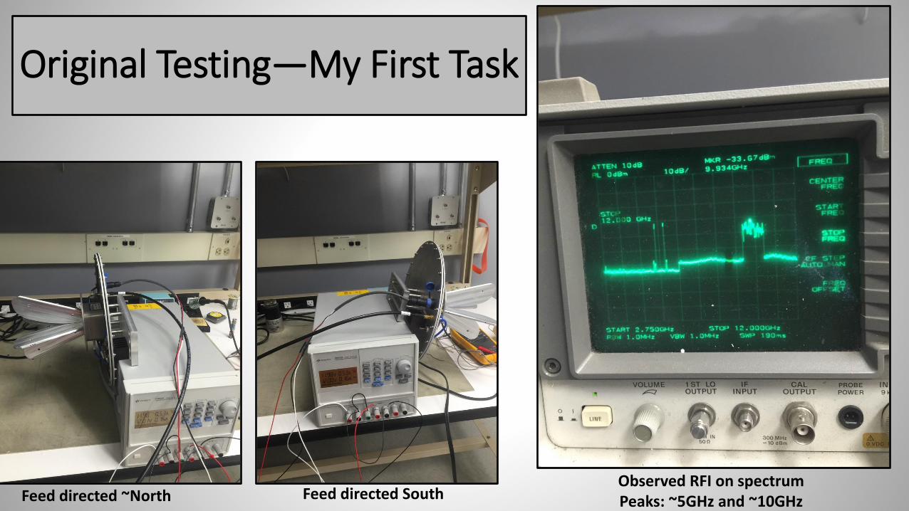
Original Testing—My First Task
Feed directed ~North Feed directed SouthObserved RFI on spectrumPeaks: ~5GHz and ~10GHz

• Spectrum analyzer for system design
• Frequency range:100kHz-18GHz
• Real-time Bandwidth: 100MHz
• Good quality for price
• Size: 10.58 x 6.81 x 2.15 inches
• Real-time Spectrum Analyzer Capabilities:
• Discovery of rare, short duration events
• Detection of transient/dynamic events
• Weak signals masked by noise
• Testing for Berkeley Nucleonics
Berkeley Nucleonics—RTSA7500

Underlying Software
• LabVIEW• Not too friendly• Plan: Morgan Goodrich’s code for VLBI system modified and simplified • Capable of controlling motors for system motion and USB RF switch for data
acquisition• Leaving behind beneficial documentation
• Berkeley RTSA7500• GUI-Graphical User Interface
• SmartMotor• Personal SMI software• Codes: hard stop, on/off command, and recording location
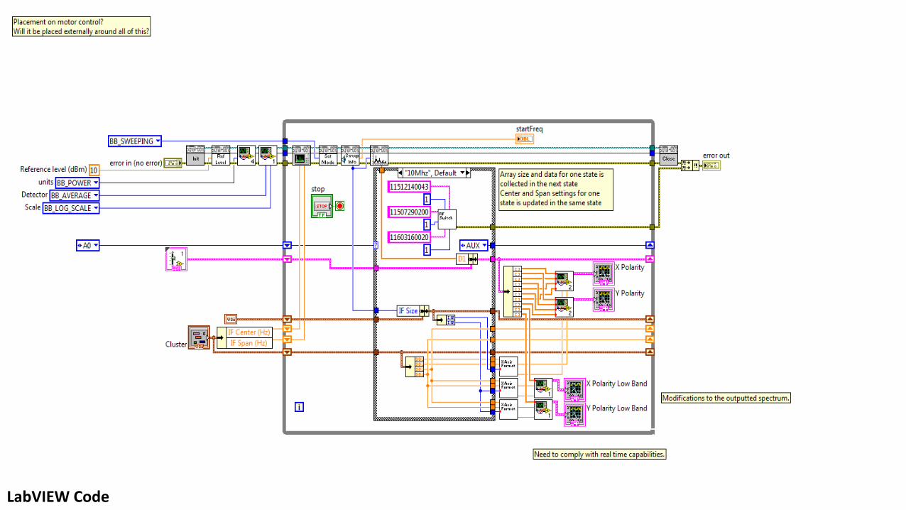
LabVIEW Code

Overview of System Improvements
• First and foremost, we needed a new radome
• Smarter motor
• Spectrum Analyzer
• No longer using benchtop—more portable
• More powerful
• Real time capabilities
• Capable of doing full sweep
• Frequency sweep band1: 1-2.9 GHz; 601 points
• Frequency sweep band2: 2.9-14 GHz; 601 points
• USB RF switch
• LabVIEW compatible, eliminates use of Arduino Image of a portion of the old system’s configuration

Future Work
• Continuing improvements to system design
• Minimizing cost
• Further modifications to LabVIEW code
• Refined understanding of motor control via SMI software
• Better means of system storage
• Big Goal: Deploying system to every VGOS site for continuous RFI scanning

Secondary Projects
• Hydrogen MASER (poster)
• VLBI work
• SRT Plans (Thanks Alan!)
Small radio telescope VLBI Mark 5 recording stationTesting Morgan’s system for VLBI
VLG-10 Hydrogen Maser
Glow from the dissociator bulb

Thank you!• Endless help, guidance, and advice from my mentors and everyone
else here at Haystack
• Unbelievable hospitality
• Mary Reynolds
• The opportunity
• Fellow REUs
• NASA Kentucky