Embed Size (px)
Citation preview
978-1-7281-3637-0/19/$31.00 ©2019 IEEE
A framework for interpreting experimental errors in VISIR
Javier García-Zubía Facultad de Ingeniería University of Deusto
Bilbao, Spain [email protected]
Jordi Cuadros
IQS University Ramón Llull
Barcelona, Spain [email protected]
Gustavo R. Alves Polytechnic of Porto
School of Engineering Porto, Portugal [email protected]
Vanessa Serrano
IQS University Ramón Llull
Barcelona, Spain [email protected]
Unai Hernández-Jayo Facultad de Ingeniería University of Deusto
Bilbao, Spain [email protected]
André Fidalgo
Polytechnic of Porto School of Engineering
Porto, Portugal [email protected]
Abstract—Students usually do errors while performing experiments. In traditional, hands-on labs, instructors are able to help students surpass those errors. In non-traditional labs, like virtual labs or simulations, the support is usually provided by built-in mechanisms that prevent erroneous actions or that provide some sort of online assistance. In remote labs, like the Virtual Instruments Systems in Reality (VISIR) remote lab, the same principle applies. This paper describes the very initial stage of a framework for interpreting experimental errors done in VISIR. It considers the course syllabus of electrical circuits and situates the work done till the moment, in relation to that syllabus. Future work is also addressed.
Keywords—remote experiments, remote lab, VISIR, electric and electronic circuits, circuit diagrams, physical circuits, errors
I. INTRODUCTION A traditional approach to teaching electric circuits is to
start with theoretical concepts and then have students doing experiments, either in the form of simulations or with real components, to consolidate the acquired knowledge. In the first case (simulations), students usually face the same graphical representations, in the form of circuit diagrams, that are used in theoretical or exercise solving classes. In the second case, i.e. experiments with real components, which can either be performed locally (in a so-called traditional laboratory) or remotely (in a so-called remote – or non-traditional – laboratory), students need to understand how to build a real physical circuit, described by a given circuit diagram [1–3]. Furthermore, they also need to conduct the experimental procedure, in particular setting up the test & measurement equipment and performing measurements [4]. While doing so, sometimes students show procedural errors or conceptual misconceptions, which may lead to hazard situations in a traditional lab [2, 3]. Doing this sort of actions in a real, remote lab provides a first opportunity for error detection, in a controlled environment, which may be quite useful to students, in particular if automated feedback is provided to them [5]. This paper addresses this particular scenario, by discussing a framework for interpreting
experimental errors done in a remote lab named Virtual Instruments Systems in Reality (VISIR).
The remainder of this paper is organized as follows: section II situates the addressed scenario in an introductory course of electrical circuits at the undergraduate level; section III describes the VISIR remote lab and the sort of experiments students and teachers may do with real electrical components and test & measurement equipment; section IV provides an initial specification of the proposed framework for interpreting experimental errors in VISIR, and; section V concludes the paper.
II. THE EDUCATIONAL SCENARIO
A. Electrical circuits theory All electrical engineering degrees include, at least, one
introductory course about electrical circuits. Moreover, many related engineering degrees, like electronics, computers, mechatronics, or even mechanical engineering, also include some level of knowledge about electrical circuits. The variety of course names is quite large, so one may preferably look into the course syllabus and look for the following contents:
• Voltage, electrical current, and resistance
• Electrical components
• Ohm’s law
• Electrical power and energy
• Joule’s law
• Voltage and current sources
• Serial, parallel and serial-parallel circuits
• Y-Δ transform
• Kirchhoff’s laws and circuit analysis methods
Usually, these contents are first delivered considering a steady electrical current delivery state, named as Direct Current (DC). Furthermore, the usual sequence is 1:1; 1:n; n:1, and n:n, where the first term corresponds to the number of Partially supported by the European Commission, through grant
561735-EPP-1-2015-1-PT-EPPKA2-CBHE-JP, and by the Foundation for Science and Technology Project, FCT UID/EQU/04730/2013.
2019 5th Experiment@ International Conference (exp.at’19)
June 12th – 14th, 2019, University of Madeira, Funchal, Madeira, Portugal
31
Authorized licensed use limited to: b-on: Instituto Politecnico do Porto. Downloaded on February 08,2021 at 16:44:54 UTC from IEEE Xplore. Restrictions apply.
power sources (usually starting with a voltage source and then with a current source) and the second term corresponds to the number of power-consuming elements (resistances). To state it clearly, the simplest circuit students start with is a single voltage source connected in series (or parallel) with a single resistor.
Notice the particularity of saying series or parallel. This is a most important concept that usually confuses students. In fact, when considering the initial and simplest 1:1 scenario, the two concepts apply. Two (or more) elements are said to be connected in series when the electrical current travelling both elements is the same. Two (or more) elements are said to connected in parallel when the voltage applied to both end terminals is the same. This means that the only situation where the two concepts overlap is precisely the simplest 1:1 circuit, and so sometimes students get confused at this very early stage.
After introducing all the formulas and laws in a DC mode, two additional elements are brought in, namely capacitors and coils. In permanent DC mode, these two elements behave as an open (infinite resistance) or short (zero resistance) circuit, if one considers its ideal characteristics. Changing the current mode to Alternate Current (AC) will cause these two elements to exhibit an impedance. Understanding that all the previously introduced laws also apply to circuits with capacitors and coils is precisely the following learning objective(s).
At an introductory level, the syllabus usually stops here, i.e. the AC mode is considered to be a pure sine wave (although some courses may also consider a DC level super-imposed to the sine wave). More advanced courses will continue with an analysis of the transient-mode, which imply differential equations. In addition, some courses will also include semiconductor elements, starting with a simple diode, then transistors, and finally operational amplifiers.
The major question, to the purpose of this contribution, is that all these concepts can be taught without performing one single hands-on experiment, using for instance simulations (or a virtual lab). In such case, there will be no room for introducing measurement equipment such as voltmeters, ammeters, or ohmmeters, and how these devices impact the circuit behavior.
B. Experiments with electrical circuits Including hands-on experiments with electrical circuits,
using real components, in a course, implies the introduction of new learning goals. In particular, and at the simplest level, describing the test & measurement equipment, how they are used, what is their impact on the circuit behavior, and understanding different representational forms, i.e. circuit diagrams vs. physical circuits [1], among others. Notice also, that hands-on experiments can be done in traditional laboratories, where students are able to directly manipulate the components and test & measurement equipment, or remotely, through remote labs [2–3, 5]. In the former case, the educational scenario may be enriched with an analysis of the differences between simulated results and real-world measurements [6–9].
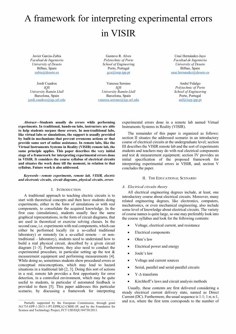
Fig. 1. A simple circuit with one voltage source connected in series / parallel with one resistor (left side); measuring the electrical current flowing through the resistor (middle); and measuring the voltage applied to the resistor (right side).
As a complementary note, one should refer the situation resulting from the Bologna process, which led to a decrease in the number of contact hours and, inevitably, to a reorganization of engineering curriculums. In many Engineering Education institutions, this led to a merging process of some courses, resulting, in particular and for instance, in the disappearance of test & measurement related courses, which were merged with courses covering electrical circuits. This merging resulted in a reduction of time needed to explore and consolidate important aspects related to the experimental procedure, e.g. the impact of test & measurement equipment in a circuit behavior.
Coming back to the sequence for introducing electrical circuits, i.e. 1:1, 1:n, n:1 and n:n, the addition of a voltmeter or an ammeter for measuring the voltage or the electrical current, respectively, will change the circuit topology. In ideal terms, these two measuring devices can be considered to have a null effect in the circuit, i.e. a voltmeter has an infinite resistance, hence the current flowing through it is zero and hence the dissipated power is also zero, according to (1). In the case of an ammeter, its internal resistance is zero and so the voltage drop at its terminals is zero, and, again according to (1) the power dissipated by the ammeter will be zero. But, in reality, these two measuring devices have a non-infinite / non-zero resistance and hence should be considered as power-dissipating elements.
P = U . I (1)
Fig. 1 illustrates the problem, by depicting the situation where no measuring instrument is used (left); an ammeter is used to measure the current flowing through the resistor (middle); and a voltmeter is used to measure the voltage applied to the resistor (right).
While the circuit depicted on the left shows a simple voltage source connected in series / parallel with the resistor, the experimental procedure to measure the current flowing through the resistor requires the introduction of one ammeter connected in series with the resistor (which cannot be said to be in parallel with the voltage source, in this situation) and the experimental procedure to measure the voltage applied to the resistor requires the introduction of one voltmeter connected in parallel with the resistor (which cannot be said to be in series with the voltage source, in this situation). With this basic experimental procedure, one shows how a simple 1:1 circuit is transformed into an 1:n circuit by simply asking a student to measure the electrical current or voltage.
2019 5th Experiment@ International Conference (exp.at’19)
June 12th – 14th, 2019, University of Madeira, Funchal, Madeira, Portugal
32
Authorized licensed use limited to: b-on: Instituto Politecnico do Porto. Downloaded on February 08,2021 at 16:44:54 UTC from IEEE Xplore. Restrictions apply.
III. THE VISIR REMOTE LAB The VISIR remote lab was first developed by Ingvar
Gustavsson, at the Blekinge Institute of Technology (BTH), Sweden [10]. Presently it is the most disseminated remote lab in the world with instances installed in Spain, Portugal, Austria, Brazil, Argentina, India, Georgia, Morocco, Costa Rica, and in Germany, more recently. Furthermore, it is the most studied remote lab in terms of didactical approaches to its insertion in engineering and also secondary school level courses [11].
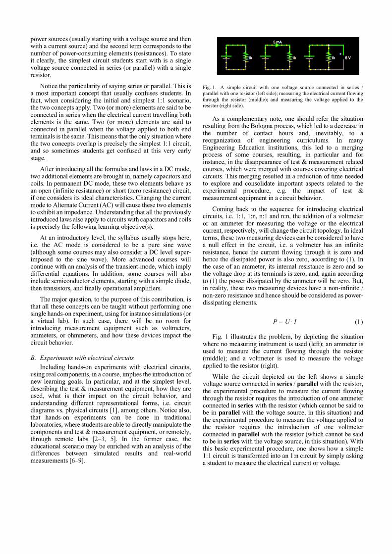
For the purpose of this submission, the main aspect to highlight about VISIR is that it includes all the basic test & measurement equipment found in a traditional workbench for doing experiments with electrical circuits, i.e.: a triple DC power source, a signal generator (AC), a multimeter, and an oscilloscope, plus a remotely controlled switching matrix that allows configuring the circuit under experimentation. The VISIR user interface includes a virtual breadboard that mimics a typical solderless breadboard also found in a traditional workbench. To understand how much it resembles a physical circuit mounted in a real breadboard, in a traditional lab, Fig. 2 illustrates the same circuit depicted by the diagram presented in Fig. 1 (right), now built in the VISIR virtual breadboard.
Fig. 2. Mesauring the voltage applied to an 1k resistor, in VISIR.
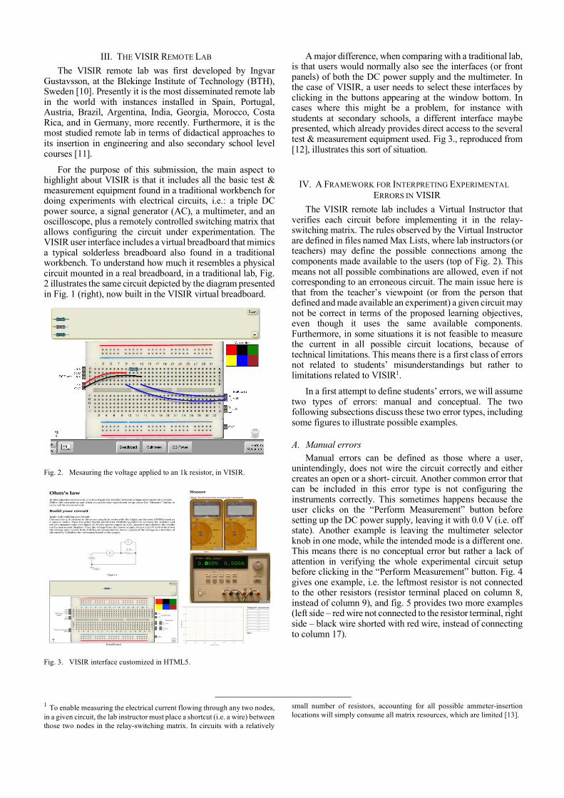
Fig. 3. VISIR interface customized in HTML5.
1 To enable measuring the electrical current flowing through any two nodes, in a given circuit, the lab instructor must place a shortcut (i.e. a wire) between those two nodes in the relay-switching matrix. In circuits with a relatively
A major difference, when comparing with a traditional lab, is that users would normally also see the interfaces (or front panels) of both the DC power supply and the multimeter. In the case of VISIR, a user needs to select these interfaces by clicking in the buttons appearing at the window bottom. In cases where this might be a problem, for instance with students at secondary schools, a different interface maybe presented, which already provides direct access to the several test & measurement equipment used. Fig 3., reproduced from [12], illustrates this sort of situation.
IV. A FRAMEWORK FOR INTERPRETING EXPERIMENTAL ERRORS IN VISIR
The VISIR remote lab includes a Virtual Instructor that verifies each circuit before implementing it in the relay-switching matrix. The rules observed by the Virtual Instructor are defined in files named Max Lists, where lab instructors (or teachers) may define the possible connections among the components made available to the users (top of Fig. 2). This means not all possible combinations are allowed, even if not corresponding to an erroneous circuit. The main issue here is that from the teacher’s viewpoint (or from the person that defined and made available an experiment) a given circuit may not be correct in terms of the proposed learning objectives, even though it uses the same available components. Furthermore, in some situations it is not feasible to measure the current in all possible circuit locations, because of technical limitations. This means there is a first class of errors not related to students’ misunderstandings but rather to limitations related to VISIR1.
In a first attempt to define students’ errors, we will assume two types of errors: manual and conceptual. The two following subsections discuss these two error types, including some figures to illustrate possible examples.
A. Manual errors Manual errors can be defined as those where a user,
unintendingly, does not wire the circuit correctly and either creates an open or a short- circuit. Another common error that can be included in this error type is not configuring the instruments correctly. This sometimes happens because the user clicks on the “Perform Measurement” button before setting up the DC power supply, leaving it with 0.0 V (i.e. off state). Another example is leaving the multimeter selector knob in one mode, while the intended mode is a different one. This means there is no conceptual error but rather a lack of attention in verifying the whole experimental circuit setup before clicking in the “Perform Measurement” button. Fig. 4 gives one example, i.e. the leftmost resistor is not connected to the other resistors (resistor terminal placed on column 8, instead of column 9), and fig. 5 provides two more examples (left side – red wire not connected to the resistor terminal, right side – black wire shorted with red wire, instead of connecting to column 17).
small number of resistors, accounting for all possible ammeter-insertion locations will simply consume all matrix resources, which are limited [13].
2019 5th Experiment@ International Conference (exp.at’19)
June 12th – 14th, 2019, University of Madeira, Funchal, Madeira, Portugal
33
Authorized licensed use limited to: b-on: Instituto Politecnico do Porto. Downloaded on February 08,2021 at 16:44:54 UTC from IEEE Xplore. Restrictions apply.
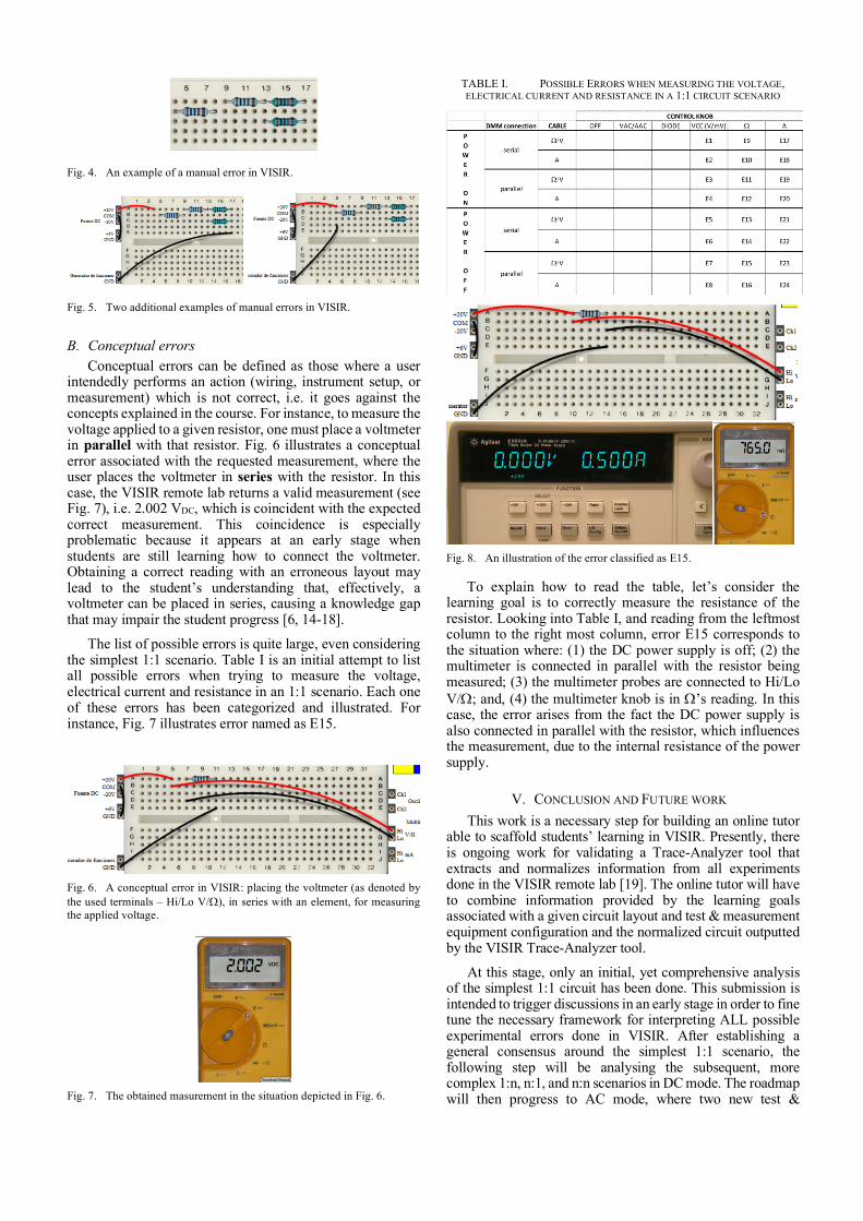
Fig. 4. An example of a manual error in VISIR.
Fig. 5. Two additional examples of manual errors in VISIR.
B. Conceptual errors Conceptual errors can be defined as those where a user
intendedly performs an action (wiring, instrument setup, or measurement) which is not correct, i.e. it goes against the concepts explained in the course. For instance, to measure the voltage applied to a given resistor, one must place a voltmeter in parallel with that resistor. Fig. 6 illustrates a conceptual error associated with the requested measurement, where the user places the voltmeter in series with the resistor. In this case, the VISIR remote lab returns a valid measurement (see Fig. 7), i.e. 2.002 VDC, which is coincident with the expected correct measurement. This coincidence is especially problematic because it appears at an early stage when students are still learning how to connect the voltmeter. Obtaining a correct reading with an erroneous layout may lead to the student’s understanding that, effectively, a voltmeter can be placed in series, causing a knowledge gap that may impair the student progress [6, 14-18].
The list of possible errors is quite large, even considering the simplest 1:1 scenario. Table I is an initial attempt to list all possible errors when trying to measure the voltage, electrical current and resistance in an 1:1 scenario. Each one of these errors has been categorized and illustrated. For instance, Fig. 7 illustrates error named as E15.
Fig. 6. A conceptual error in VISIR: placing the voltmeter (as denoted by the used terminals – Hi/Lo V/W), in series with an element, for measuring the applied voltage.
Fig. 7. The obtained masurement in the situation depicted in Fig. 6.
TABLE I. POSSIBLE ERRORS WHEN MEASURING THE VOLTAGE, ELECTRICAL CURRENT AND RESISTANCE IN A 1:1 CIRCUIT SCENARIO
Fig. 8. An illustration of the error classified as E15.
To explain how to read the table, let’s consider the learning goal is to correctly measure the resistance of the resistor. Looking into Table I, and reading from the leftmost column to the right most column, error E15 corresponds to the situation where: (1) the DC power supply is off; (2) the multimeter is connected in parallel with the resistor being measured; (3) the multimeter probes are connected to Hi/Lo V/W; and, (4) the multimeter knob is in W’s reading. In this case, the error arises from the fact the DC power supply is also connected in parallel with the resistor, which influences the measurement, due to the internal resistance of the power supply.
V. CONCLUSION AND FUTURE WORK This work is a necessary step for building an online tutor
able to scaffold students’ learning in VISIR. Presently, there is ongoing work for validating a Trace-Analyzer tool that extracts and normalizes information from all experiments done in the VISIR remote lab [19]. The online tutor will have to combine information provided by the learning goals associated with a given circuit layout and test & measurement equipment configuration and the normalized circuit outputted by the VISIR Trace-Analyzer tool.
At this stage, only an initial, yet comprehensive analysis of the simplest 1:1 circuit has been done. This submission is intended to trigger discussions in an early stage in order to fine tune the necessary framework for interpreting ALL possible experimental errors done in VISIR. After establishing a general consensus around the simplest 1:1 scenario, the following step will be analysing the subsequent, more complex 1:n, n:1, and n:n scenarios in DC mode. The roadmap will then progress to AC mode, where two new test &
2019 5th Experiment@ International Conference (exp.at’19)
June 12th – 14th, 2019, University of Madeira, Funchal, Madeira, Portugal
34
Authorized licensed use limited to: b-on: Instituto Politecnico do Porto. Downloaded on February 08,2021 at 16:44:54 UTC from IEEE Xplore. Restrictions apply.
measurement instruments, i.e. the signal generator and the oscilloscope will be added. Considering the number of control knobs exhibited by these two more complex test & measurement instruments, it will be quite difficult to represent all possible errors in a page-sized table. This means the framework will have to evolve to a machine-readable table, accounting for all possible combinations. At that stage, it will be more difficult to perform a manual validation and therefore computational techniques will have to be applied.
ACKNOWLEDGMENTS The authors would like to acknowledge the support of all
students who contributed anonymously to this work. Furthermore, the authors would like to acknowledge the support of the VISIR Special Interest Group (VISIR SIG) as well as the financial support provided by the European Commission through grant 561735-EPP-1-2015-1-PT-EPPKA2-CBHE-JP. Finally, the authors would also like to acknowledge the financial support provided by the Foundation for Science and Technology Project, FCT UID/EQU/04730/2013.
REFERENCES [1] K. DesPortes, A. Anupam, N. Pathak and B. DiSalvo, "Circuit
diagrams vs. physical circuits: The effect of representational forms during assessment," 2016 IEEE Frontiers in Education Conference (FIE), Erie, PA, USA, 2016, pp. 1-9.
[2] J. Ma and J. V. Nickerson, “Hands-on, simulated, and remote laboratories: A comparative literature review,” ACM Computing Surveys (CSUR), vol. 38, no. 3, p. 7, 2006.
[3] J. R. Brinson, "Learning outcome achievment in non-traditional (virtual and remote) versus traditional (hands-on) laboratories: A review of the empirical reserach," Computers & Education, vol. 87, pp. 218-237, 2015.
[4] L. D. Feisel and A. J. Rose, “The role of the laboratory in undergraduate engineering education,” Engineering Education, vol. 94, no. 1, pp. 121-130, 2005.
[5] I. Gustavsson et al., “On Objectives of Instructional Laboratories, Individual Assessment, and Use of Collaborative Remote Laboratories,” IEEE Trans. Learning Technologies, 2(4), 263 – 274, 2009.
[6] Zacharias C. Zacharia, “Comparing and combining real and virtual experimentation: an effort to enhance students’ conceptual understanding of electric circuits,” Journal of Computer Assisted Learning, vol. 23, no. 2, pp. 120-132, 2007.
[7] C. Viegas, N. Lima, G. R. Alves and I. Gustavsson, “Improving students experimental competences using simultaneous methods in class and in assessments”, TEEM’14 Proceedings of the 2nd International Conference on Technological Ecosystems for Enhancing Multiculturality, ACM New York, pp. 125-132, 2014.
[8] M. V. Branco, L. A. Coelho, L. Schlichting and G. R. Alves, "Differentiating simulations and remote (real) experiments", 5th Technological Ecosystems for Enhancing Multiculturality (TEEM’17), Cádiz, Spain, October 18-20, 2017.
[9] N. Lima et al., "Do Students Really Understand the Difference Between Simulation and Remote Labs?", 5th Technological Ecosystems for Enhancing Multiculturality (TEEM’17), Cádiz, Spain, October 18-20, 2017.
[10] I. Gustavsson, “A remote access laboratory for electrical circuit experiments,” International Journal of Engineering Education, vol. 19, 2003.
[11] N. Lima, C. Viegas, G. R. Alves and F. J. García-Peñalvo; "VISIR’s Usage as a Learning Resource: a Review of the Empirical Research", 4th Technological Ecosystems for Enhancing Multiculturality (TEEM’16), Salamanca, Spain, November 2-4, 2016.
[12] L. Claesson, I. Khan, J. Zachrisson, K. Nilsson, I. Gustavsson, L. Håkansson, Chapter 7 – “Using a VISIR laboratory to supplement teaching and learning processes in physics courses in a Swedish Upper Secondary School” in IT Innovative Practices in Secondary Schools: Remote Experiments, O. Dziabenko and J. García Zubía (ed.), University of Deusto, Bilbao, Spain, 2013, ISBN: 978-84-15759-16-4.
[13] A. V. Fidalgo et al., "Using Remote Labs to Serve Different Teacher’s Needs - A Case Study with VISIR and RemotElectLab”, International Journal of Online Engineering (iJOE), ISSN 1861-2121, Vol. 8, Special Issue: REV2012 (1), pp. 36-41, 2012.
[14] Clara Viegas et al., "Impact of a Remote Lab on Teaching Practices and Students Learning", Computers & Education, 2018.
[15] Gustavo R. Alves, M. C. Viegas, N. Lima, and I. Gustavsson, “Simultaneous Usage of Methods for the Development of Experimental Competences”, International Journal of Human Capital and Information Technology Professionals, 7(1), 54-73, January-March, 2016.
[16] M. A. Marques, M. C. Viegas, M. C. Costa-Lobo, A. V. Fidalgo, G. R. Alves, J. S. Rocha, J.S.; Gustavsson, I., "How Remote Labs Impact on Course Outcomes: Various Practices Using VISIR," Education, IEEE Transactions on, vol. 57, no. 3, pp. 151-159, Aug. 2014.
[17] Natércia Lima, Clara Viegas, Maria Arcelina Marques, Gustavo R. Alves, and Francisco José García Peñalvo, "Macro Analysis on how to Potentiate Experimental Competences Using VISIR", Proceedings of the 6th Technological Ecosystems for Enhacing Multiculturality (TEEM), Salamanca, Spain, 24-26 October 2018.
[18] Alexandre Gonçalves, Gustavo R. Alves, Lucas Soares, Juarez B. Silva, and João B. Alves, "Remote Experimentation supported by Learning Analytics and Recommender Systems", Proceedings of the 6th Technological Ecosystems for Enhacing Multiculturality (TEEM), Salamanca, Spain, 24-26 October 2018.
[19] https://github.com/vanessaserrano/visirTR, accessed March 9th, 2019.
2019 5th Experiment@ International Conference (exp.at’19)
June 12th – 14th, 2019, University of Madeira, Funchal, Madeira, Portugal
35
Authorized licensed use limited to: b-on: Instituto Politecnico do Porto. Downloaded on February 08,2021 at 16:44:54 UTC from IEEE Xplore. Restrictions apply.