Embed Size (px)
Citation preview
BIG-IP® TMOS®: Tunneling and IPsec
Version 12.1

Table of Contents
Creating IP Tunnels....................................................................................................................7
About IP tunnels.................................................................................................................7
About point-to-point tunnels...............................................................................................7
Creating a point-to-point IP tunnel...........................................................................8
Assigning a self IP address to an IP tunnel endpoint..............................................8
Routing traffic through an IP tunnel interface..........................................................9
Example of a point-to-point IP tunnel configuration.................................................9
About tunnels between the BIG-IP system and other devices.........................................10
Creating an encapsulation tunnel between a BIG-IP device and multiple
devices.............................................................................................................10
About transparent tunnels................................................................................................11
Creating a transparent tunnel................................................................................11
About the traffic group setting for tunnels........................................................................12
Configuring Network Virtualization Tunnels..........................................................................13
Overview: Configuring network virtualization tunnels......................................................13
About network virtualization tunnels on the BIG-IP system..................................14
Virtualized network terminology............................................................................14
Centralized vs. decentralized models of network virtualization.............................15
About network virtualization tunnel types..............................................................16
About statically configured network virtualization tunnels................................................17
Considerations for statically configured network virtualization tunnels.................17
Examples for manually populating L2 location records.........................................17
Sample NVGRE configuration using tmsh.............................................................19
Sample VXLAN unicast configuration using tmsh.................................................20
Sample command for virtual server to listen on a VXLAN tunnel.........................21
Commands for viewing tunnel statistics................................................................21
About VXLAN multicast configuration..............................................................................21
About bridging VLAN and VXLAN networks.........................................................21
Considerations for configuring multicast VXLAN tunnels......................................22
Task summary.......................................................................................................22
About configuring VXLAN tunnels on high availability BIG-IP device pairs...........24
About configuring VXLAN tunnels using OVSDB.............................................................25
Setting up the OVSDB management component..................................................25
About configuring VXLAN-GPE tunnels...........................................................................26
Creating a multicast VXLAN-GPE tunnel..............................................................26
Configuring NVGRE Tunnels for HA-Paired Devices.............................................................29
Overview: Configuring NVGRE tunnels for HA-paired devices........................................29
3
Table of Contents
About Microsoft Hyper-V representation of tunnels...............................................30
About configuration of NVGRE tunnels in an HA pair...........................................30
Creating an NVGRE tunnel in an HA configuration...............................................30
Configuring the BIG-IP System as an HNV Gateway.............................................................33
Overview: Using the BIG-IP system as a Hyper-V Network Virtualization gateway.........33
Creating per-subnet tunnels for Hyper-V Network Virtualization routing
domains............................................................................................................33
Configuring an EtherIP Tunnel................................................................................................35
Overview: Preserving BIG-IP connections during live virtual machine migration............35
Illustration of EtherIP tunneling in a VMotion environment....................................35
Task summary..................................................................................................................36
Creating a VLAN...................................................................................................36
Creating an EtherIP tunnel object.........................................................................37
Creating a VLAN group.........................................................................................37
Creating a self IP address.....................................................................................38
Creating a self IP for a VLAN group......................................................................38
Creating a Virtual Location monitor.......................................................................39
Syncing the BIG-IP configuration to the device group...........................................40
Implementation result.......................................................................................................40
Securing EtherIP Tunnel Traffic with IPsec............................................................................41
Overview: Securing EtherIP tunnel traffic with IPsec.......................................................41
Creating a VLAN...................................................................................................41
Creating an EtherIP tunnel object.........................................................................42
Creating a VLAN group.........................................................................................42
Creating a self IP address.....................................................................................43
Creating a self IP for a VLAN group......................................................................44
Creating a custom IPsec policy for EtherIP tunnel traffic......................................44
Creating an IPsec traffic selector for EtherIP traffic...............................................45
Implementation result.......................................................................................................45
Configuring IPsec in Tunnel Mode between Two BIG-IP Systems.......................................47
Overview: Configuring IPsec between two BIG-IP systems.............................................47
About negotiation of security associations............................................................47
About IPsec Tunnel mode.....................................................................................47
About BIG-IP components of the IPsec protocol suite..........................................48
About IP Payload Compression Protocol (IPComp)..............................................48
Task summary..................................................................................................................48
Creating a forwarding virtual server for IPsec.......................................................49
Creating a custom IPsec policy.............................................................................49
Creating a bidirectional IPsec traffic selector........................................................50
4
Table of Contents
Creating an IKE peer.............................................................................................52
Verifying IPsec connectivity for Tunnel mode........................................................53
Implementation result.......................................................................................................57
Configuring IPsec in Transport Mode between Two BIG-IP Systems..................................59
Overview: Configuring IPsec in Transport mode between two BIG-IP systems...............59
About negotiation of security associations............................................................59
About IPsec Transport mode.................................................................................59
About BIG-IP components of the IPsec protocol suite..........................................60
About IP Payload Compression Protocol (IPComp)..............................................60
Task summary..................................................................................................................60
Creating a forwarding virtual server for IPsec.......................................................61
Creating an IKE peer.............................................................................................61
Creating a bidirectional IPsec policy.....................................................................63
Creating a bidirectional IPsec traffic selector........................................................63
Verifying IPsec connectivity for Transport mode....................................................64
Implementation result.......................................................................................................68
Configuring IPsec in Interface Mode between Two BIG-IP Systems...................................69
Overview: Configuring IPsec in Interface mode between two BIG-IP systems................69
Task summary..................................................................................................................69
Creating a forwarding virtual server for IPsec.......................................................70
Creating a custom IPsec policy for Interface mode...............................................70
Creating an IPsec traffic selector..........................................................................70
Specifying an IPsec tunnel interface traffic selector..............................................71
Creating an IPsec interface tunnel........................................................................71
Assigning a self IP address to an IP tunnel endpoint............................................72
Assigning a self IP address to an IP tunnel endpoint............................................72
Configuring IPsec between a BIG-IP System and a Third-Party Device..............................75
Overview: Configuring IPsec between a BIG-IP system and a third-party device...........75
About negotiation of security associations............................................................75
About IPsec Tunnel mode.....................................................................................76
About BIG-IP components of the IPsec protocol suite..........................................76
Task summary..................................................................................................................76
Creating a forwarding virtual server for IPsec.......................................................77
Creating an IKE peer.............................................................................................77
Creating a custom IPsec policy.............................................................................79
Creating a bidirectional IPsec traffic selector........................................................80
Verifying IPsec connectivity for Tunnel mode........................................................81
Implementation result.......................................................................................................85
Configuring IPsec Using Manually Keyed Security Associations........................................87
5
Table of Contents
Overview: Configuring IPsec using manually keyed security associations......................87
About IPsec Tunnel mode.....................................................................................88
Task summary..................................................................................................................88
Creating a forwarding virtual server for IPsec.......................................................88
Creating custom IPsec policies for manual security associations.........................89
Manually creating IPsec security associations for inbound and outbound
traffic.................................................................................................................90
Creating IPsec traffic selectors for manually keyed security associations............91
Verifying IPsec connectivity for Tunnel mode........................................................92
Setting Up IPsec To Use NAT Traversal on Both Sides of the WAN.....................................95
Overview: Setting up IPsec to use NAT traversal on both sides of the WAN...................95
Before you begin IPsec configuration...............................................................................95
Task summary..................................................................................................................95
Creating a forwarding virtual server for IPsec.......................................................96
Creating an IPsec tunnel with NAT-T on both sides..............................................96
Verifying IPsec connectivity for Tunnel mode........................................................99
Setting Up IPsec To Use NAT Traversal on One Side of the WAN......................................105
Overview: Setting up IPsec to use NAT traversal on one side of the WAN....................105
Before you begin IPsec configuration.............................................................................105
Task summary................................................................................................................105
Creating a forwarding virtual server for IPsec.....................................................106
Creating an IPsec tunnel with NAT-T on one side...............................................106
Verifying IPsec connectivity for Tunnel mode......................................................110
Diagnosing IPsec Tunnel Issues...........................................................................................115
Overview: Diagnosing IPsec tunnel issues....................................................................115
Viewing the IPsec diagnostics.............................................................................115
IPsec Diagnostics Example............................................................................................115
Legal Notices..........................................................................................................................117
Legal notices..................................................................................................................117
6
Table of Contents
Creating IP Tunnels
About IP tunnels
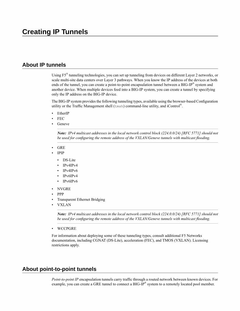
Using F5® tunneling technologies, you can set up tunneling from devices on different Layer 2 networks, orscale multi-site data centers over Layer 3 pathways. When you know the IP address of the devices at bothends of the tunnel, you can create a point-to-point encapsulation tunnel between a BIG-IP® system andanother device. When multiple devices feed into a BIG-IP system, you can create a tunnel by specifyingonly the IP address on the BIG-IP device.
The BIG-IP system provides the following tunneling types, available using the browser-based Configurationutility or the Traffic Management shell (tmsh) command-line utility, and iControl®.
• EtherIP• FEC• Geneve
Note: IPv4 multicast addresses in the local network control block (224.0.0/24) [RFC 5771] should notbe used for configuring the remote address of the VXLAN/Geneve tunnels with multicast flooding.
• GRE• IPIP
• DS-Lite• IPv4IPv4• IPv4IPv6• IPv6IPv4• IPv6IPv6
• NVGRE• PPP• Transparent Ethernet Bridging• VXLAN
Note: IPv4 multicast addresses in the local network control block (224.0.0/24) [RFC 5771] should notbe used for configuring the remote address of the VXLAN/Geneve tunnels with multicast flooding.
• WCCPGRE
For information about deploying some of these tunneling types, consult additional F5 Networksdocumentation, including CGNAT (DS-Lite), acceleration (FEC), and TMOS (VXLAN). Licensingrestrictions apply.
About point-to-point tunnels
Point-to-point IP encapsulation tunnels carry traffic through a routed network between known devices. Forexample, you can create a GRE tunnel to connect a BIG-IP® system to a remotely located pool member.
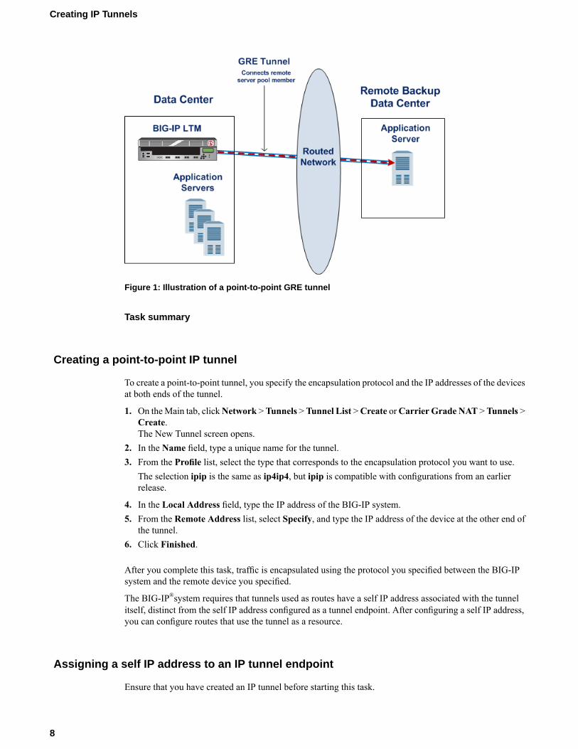
Figure 1: Illustration of a point-to-point GRE tunnel
Task summary
Creating a point-to-point IP tunnel
To create a point-to-point tunnel, you specify the encapsulation protocol and the IP addresses of the devicesat both ends of the tunnel.
1. On theMain tab, clickNetwork >Tunnels >Tunnel List >Create orCarrier Grade NAT >Tunnels >Create.The New Tunnel screen opens.
2. In the Name field, type a unique name for the tunnel.3. From the Profile list, select the type that corresponds to the encapsulation protocol you want to use.
The selection ipip is the same as ip4ip4, but ipip is compatible with configurations from an earlierrelease.
4. In the Local Address field, type the IP address of the BIG-IP system.5. From the Remote Address list, select Specify, and type the IP address of the device at the other end of
the tunnel.6. Click Finished.
After you complete this task, traffic is encapsulated using the protocol you specified between the BIG-IPsystem and the remote device you specified.
The BIG-IP®system requires that tunnels used as routes have a self IP address associated with the tunnelitself, distinct from the self IP address configured as a tunnel endpoint. After configuring a self IP address,you can configure routes that use the tunnel as a resource.
Assigning a self IP address to an IP tunnel endpoint
Ensure that you have created an IP tunnel before starting this task.
8
Creating IP Tunnels
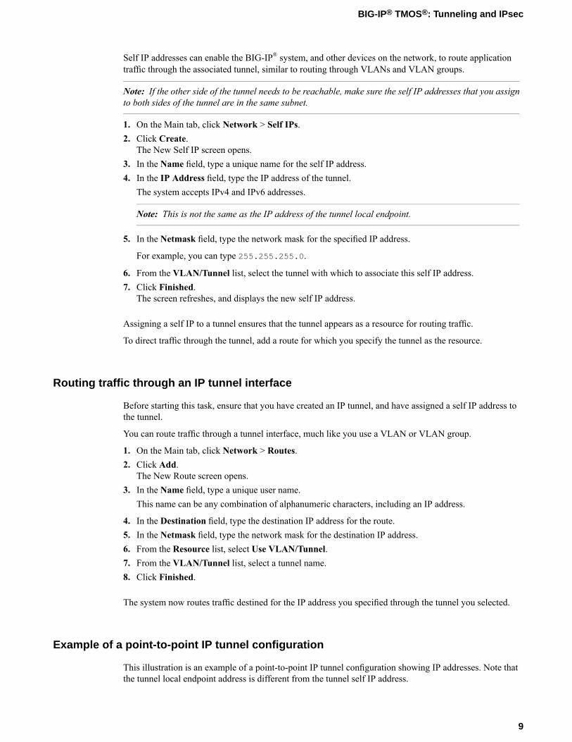
Self IP addresses can enable the BIG-IP® system, and other devices on the network, to route applicationtraffic through the associated tunnel, similar to routing through VLANs and VLAN groups.
Note: If the other side of the tunnel needs to be reachable, make sure the self IP addresses that you assignto both sides of the tunnel are in the same subnet.
1. On the Main tab, click Network > Self IPs.2. Click Create.
The New Self IP screen opens.3. In the Name field, type a unique name for the self IP address.4. In the IP Address field, type the IP address of the tunnel.
The system accepts IPv4 and IPv6 addresses.
Note: This is not the same as the IP address of the tunnel local endpoint.
5. In the Netmask field, type the network mask for the specified IP address.
For example, you can type 255.255.255.0.
6. From the VLAN/Tunnel list, select the tunnel with which to associate this self IP address.7. Click Finished.
The screen refreshes, and displays the new self IP address.
Assigning a self IP to a tunnel ensures that the tunnel appears as a resource for routing traffic.
To direct traffic through the tunnel, add a route for which you specify the tunnel as the resource.
Routing traffic through an IP tunnel interface
Before starting this task, ensure that you have created an IP tunnel, and have assigned a self IP address tothe tunnel.
You can route traffic through a tunnel interface, much like you use a VLAN or VLAN group.
1. On the Main tab, click Network > Routes.2. Click Add.
The New Route screen opens.3. In the Name field, type a unique user name.
This name can be any combination of alphanumeric characters, including an IP address.
4. In the Destination field, type the destination IP address for the route.5. In the Netmask field, type the network mask for the destination IP address.6. From the Resource list, select Use VLAN/Tunnel.7. From the VLAN/Tunnel list, select a tunnel name.8. Click Finished.
The system now routes traffic destined for the IP address you specified through the tunnel you selected.
Example of a point-to-point IP tunnel configuration
This illustration is an example of a point-to-point IP tunnel configuration showing IP addresses. Note thatthe tunnel local endpoint address is different from the tunnel self IP address.
9
BIG-IP® TMOS®: Tunneling and IPsec
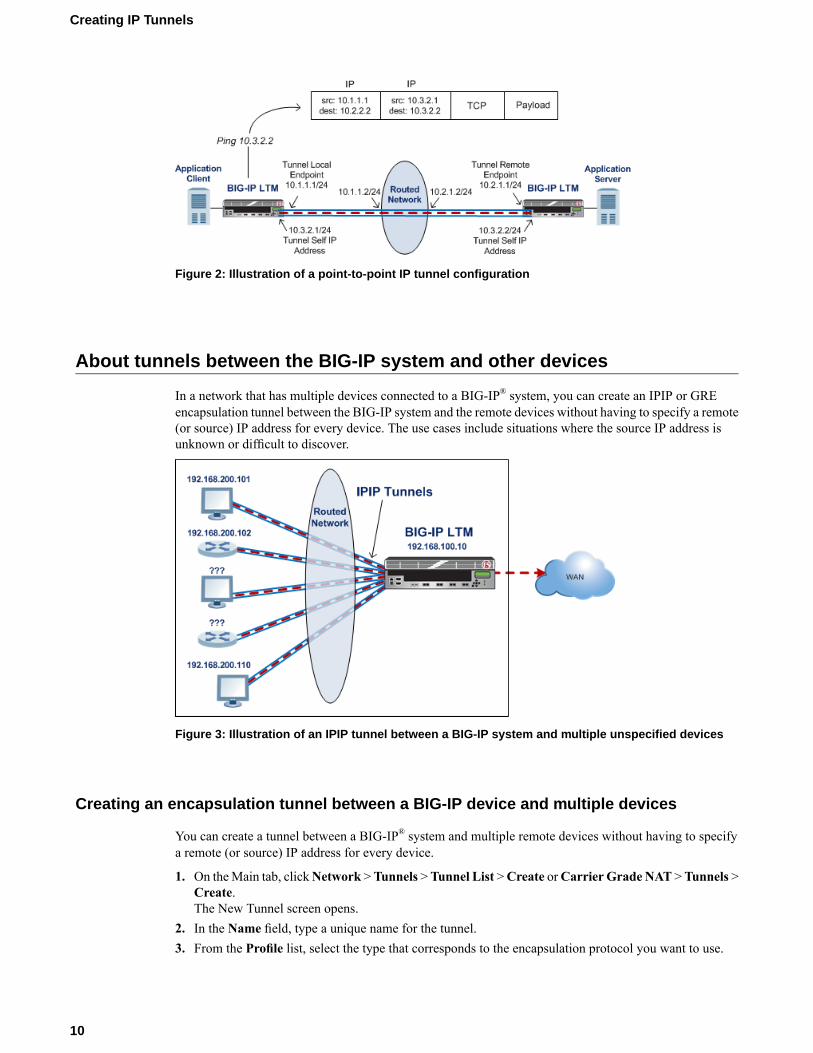
Figure 2: Illustration of a point-to-point IP tunnel configuration
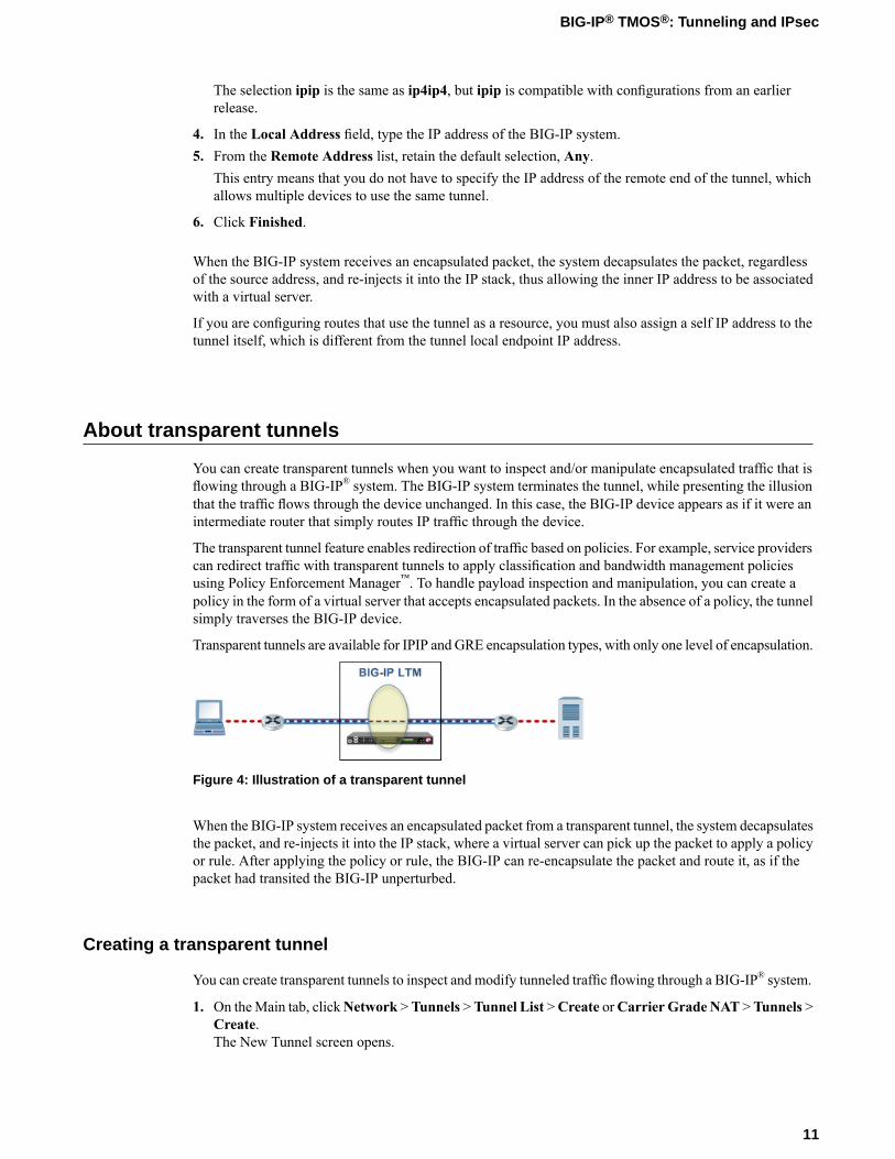
About tunnels between the BIG-IP system and other devices
In a network that has multiple devices connected to a BIG-IP® system, you can create an IPIP or GREencapsulation tunnel between the BIG-IP system and the remote devices without having to specify a remote(or source) IP address for every device. The use cases include situations where the source IP address isunknown or difficult to discover.
Figure 3: Illustration of an IPIP tunnel between a BIG-IP system and multiple unspecified devices
Creating an encapsulation tunnel between a BIG-IP device and multiple devices
You can create a tunnel between a BIG-IP® system and multiple remote devices without having to specifya remote (or source) IP address for every device.
1. On theMain tab, clickNetwork >Tunnels >Tunnel List >Create orCarrier Grade NAT >Tunnels >Create.The New Tunnel screen opens.
2. In the Name field, type a unique name for the tunnel.3. From the Profile list, select the type that corresponds to the encapsulation protocol you want to use.
10
Creating IP Tunnels
The selection ipip is the same as ip4ip4, but ipip is compatible with configurations from an earlierrelease.
4. In the Local Address field, type the IP address of the BIG-IP system.5. From the Remote Address list, retain the default selection, Any.
This entry means that you do not have to specify the IP address of the remote end of the tunnel, whichallows multiple devices to use the same tunnel.
6. Click Finished.
When the BIG-IP system receives an encapsulated packet, the system decapsulates the packet, regardlessof the source address, and re-injects it into the IP stack, thus allowing the inner IP address to be associatedwith a virtual server.
If you are configuring routes that use the tunnel as a resource, you must also assign a self IP address to thetunnel itself, which is different from the tunnel local endpoint IP address.
About transparent tunnels
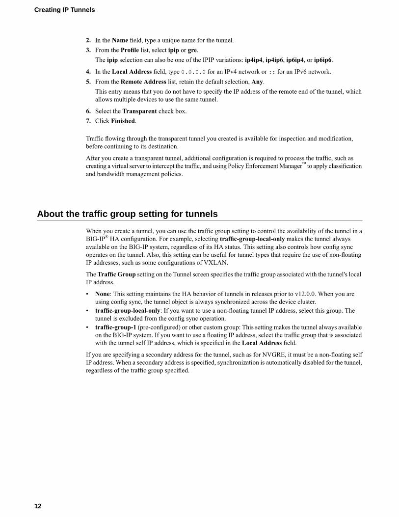
You can create transparent tunnels when you want to inspect and/or manipulate encapsulated traffic that isflowing through a BIG-IP® system. The BIG-IP system terminates the tunnel, while presenting the illusionthat the traffic flows through the device unchanged. In this case, the BIG-IP device appears as if it were anintermediate router that simply routes IP traffic through the device.
The transparent tunnel feature enables redirection of traffic based on policies. For example, service providerscan redirect traffic with transparent tunnels to apply classification and bandwidth management policiesusing Policy Enforcement Manager™. To handle payload inspection and manipulation, you can create apolicy in the form of a virtual server that accepts encapsulated packets. In the absence of a policy, the tunnelsimply traverses the BIG-IP device.
Transparent tunnels are available for IPIP and GRE encapsulation types, with only one level of encapsulation.
Figure 4: Illustration of a transparent tunnel
When the BIG-IP system receives an encapsulated packet from a transparent tunnel, the system decapsulatesthe packet, and re-injects it into the IP stack, where a virtual server can pick up the packet to apply a policyor rule. After applying the policy or rule, the BIG-IP can re-encapsulate the packet and route it, as if thepacket had transited the BIG-IP unperturbed.
Creating a transparent tunnel
You can create transparent tunnels to inspect and modify tunneled traffic flowing through a BIG-IP® system.
1. On theMain tab, clickNetwork >Tunnels >Tunnel List >Create orCarrier Grade NAT >Tunnels >Create.The New Tunnel screen opens.
11
BIG-IP® TMOS®: Tunneling and IPsec
2. In the Name field, type a unique name for the tunnel.3. From the Profile list, select ipip or gre.
The ipip selection can also be one of the IPIP variations: ip4ip4, ip4ip6, ip6ip4, or ip6ip6.
4. In the Local Address field, type 0.0.0.0 for an IPv4 network or :: for an IPv6 network.5. From the Remote Address list, retain the default selection, Any.
This entry means that you do not have to specify the IP address of the remote end of the tunnel, whichallows multiple devices to use the same tunnel.
6. Select the Transparent check box.7. Click Finished.
Traffic flowing through the transparent tunnel you created is available for inspection and modification,before continuing to its destination.
After you create a transparent tunnel, additional configuration is required to process the traffic, such ascreating a virtual server to intercept the traffic, and using Policy EnforcementManager™ to apply classificationand bandwidth management policies.
About the traffic group setting for tunnels
When you create a tunnel, you can use the traffic group setting to control the availability of the tunnel in aBIG-IP® HA configuration. For example, selecting traffic-group-local-only makes the tunnel alwaysavailable on the BIG-IP system, regardless of its HA status. This setting also controls how config syncoperates on the tunnel. Also, this setting can be useful for tunnel types that require the use of non-floatingIP addresses, such as some configurations of VXLAN.
The Traffic Group setting on the Tunnel screen specifies the traffic group associated with the tunnel's localIP address.
• None: This setting maintains the HA behavior of tunnels in releases prior to v12.0.0. When you areusing config sync, the tunnel object is always synchronized across the device cluster.
• traffic-group-local-only: If you want to use a non-floating tunnel IP address, select this group. Thetunnel is excluded from the config sync operation.
• traffic-group-1 (pre-configured) or other custom group: This setting makes the tunnel always availableon the BIG-IP system. If you want to use a floating IP address, select the traffic group that is associatedwith the tunnel self IP address, which is specified in the Local Address field.
If you are specifying a secondary address for the tunnel, such as for NVGRE, it must be a non-floating selfIP address. When a secondary address is specified, synchronization is automatically disabled for the tunnel,regardless of the traffic group specified.
12
Creating IP Tunnels
Configuring Network Virtualization Tunnels
Overview: Configuring network virtualization tunnels
Large data centers and cloud service providers are benefiting from large scale network virtualization.Network Virtualization provides connectivity in cloud environments by overlaying Layer 2 segments overa Layer 3 infrastructure. The overlay network can be dynamically extendedwithmultiple virtualized networkswithout affecting the Layer 3 infrastructure. This number of virtualized networks is typically much largerthan the number of VLANS the infrastructure can support.
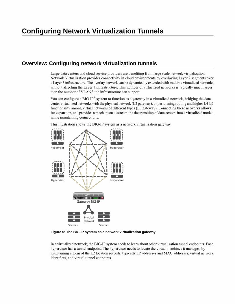
You can configure a BIG-IP® system to function as a gateway in a virtualized network, bridging the datacenter virtualized networks with the physical network (L2 gateway), or performing routing and higher L4-L7functionality among virtual networks of different types (L3 gateway). Connecting these networks allowsfor expansion, and provides a mechanism to streamline the transition of data centers into a virtualized model,while maintaining connectivity.
This illustration shows the BIG-IP system as a network virtualization gateway.
Figure 5: The BIG-IP system as a network virtualization gateway
In a virtualized network, the BIG-IP system needs to learn about other virtualization tunnel endpoints. Eachhypervisor has a tunnel endpoint. The hypervisor needs to locate the virtual machines it manages, bymaintaining a form of the L2 location records, typically, IP addresses and MAC addresses, virtual networkidentifiers, and virtual tunnel endpoints.
About network virtualization tunnels on the BIG-IP system
When you configure a BIG-IP® system as a network virtualization gateway, the system represents theconnection as a tunnel, which provides a Layer 2 interface on the virtual network. You can use the tunnelinterface in both Layer 2 and Layer 3 configurations. After you create the network virtualization tunnels,you can use the tunnels like you use VLANs on a BIG-IP system, such as for routing, assigning self IPaddresses, and associating with virtual servers.
Creating a network virtualization tunnel
Creating a network virtualization tunnel on a BIG-IP® system provides an L2 gateway to connect the physicalunderlay network with a virtual overlay network.
1. On theMain tab, clickNetwork >Tunnels >Tunnel List >Create orCarrier Grade NAT >Tunnels >Create.The New Tunnel screen opens.
2. In the Name field, type a unique name for the tunnel.3. From the Profile list, select the tunnel profile you created for network virtualization.
This selection must be a profile based on either the gre or vxlan parent profile, depending on yourvirtualized network environment.
4. In the Local Address field, type the self IP address of the VLAN through which the remote hypervisoris reachable.
5. For the Remote Address list, retain the default selection, Any.6. In the Key field, type the VNI (Virtual Network Identifier) to use for a VXLAN tunnel or the Virtual
Subnet Identifier (VSID) to use for a NVGRE tunnel.This field appears above the Profile field when you select a profile that requires this setting.
7. Click Finished.
This tunnel is now available to use in virtualized network routing configurations, depending on how youconfigure your network.
Virtualized network terminology
These terms are associated with virtualized networks.
forwarding database (FDB)The FDB is the database that contains mappings between the MAC address of each virtual machine andthe IP address of the hypervisor machine on which it resides.
L2 gatewayThe Layer 2 gateway performs the bridge functionality between VLAN and virtual segments in avirtualized network.
L3 gatewayThe Layer 3 gateway performs routing and higher L4-L7 functionality among virtualized networksegments of different types.
overlay networkThe overlay network is a virtual network of VMs built on top of a stable L2-L3 structure. The view fromone VM to another is as if they were on the same switch, but, in fact, they could be far afield.
14
Configuring Network Virtualization Tunnels
tunnel endpointA tunnel endpoint originates or terminates a tunnel. In a virtualized network environment, the tunnelIP addresses are part of the L2 underlay network. The same local IP address can be used for multipletunnels.
underlay networkThe underlay network is the L2 or L3 routed physical network, a mesh of tunnels.
virtualized networkA virtualized network is when you create a virtual L2 or L3 topology on top of a stable physical L2 orL3 network. Connectivity in the virtual topology is provided by tunneling Ethernet frames in IP overthe physical network.
VNIThe Virtual Network Identifier (VNI) is also called the VXLAN segment ID. The system uses the VNIto identify the appropriate tunnel.
VSIDThe Virtual Subnet Identifier (VSID) is a 24-bit identifier used in an NVGRE environment that representsa virtual L2 broadcast domain, enabling routes to be configured between virtual subnets.
VTEPThe VXLAN Tunnel Endpoint (VTEP) originates or terminates a VXLAN tunnel. The same local IPaddress can be used for multiple tunnels.
VXLANVirtual eXtended LAN (VXLAN) is a network virtualization scheme that overlays Layer 2 over Layer 3.VLXAN uses Layer 3 multicast to support the transmission of multicast and broadcast traffic in thevirtual network, while decoupling the virtualized network from the physical infrastructure.
VXLAN gatewayA VXLAN gateway bridges traffic between VXLAN and non-VXLAN environments. The BIG-IP®system uses a VXLAN gateway to bridge a traditional VLAN and a VXLAN network, by becoming anetwork virtualization endpoint.
VXLAN headerIn addition to the UDP header, encapsulated packets include a VXLAN header, which carries a 24-bitVNI to uniquely identify Layer 2 segments within the overlay.
VXLAN segmentA VXLAN segment is a Layer 2 overlay network over which VMs communicate. Only VMs within thesame VXLAN segment can communicate with each other.
Centralized vs. decentralized models of network virtualization
Using the BIG-IP® system as a network virtualization gateway, you can set up virtualized network segmentsusing either a centralized or decentralized model.
Centralized model
In a centralized model, a network orchestrator or controller manages the virtualized network segments. Theorchestrator has full view of VTEPs, L2, and L3 information in the overlay, and is responsible for pushingthis information to hypervisors and gateways. Microsoft Hyper-V and VMware NSX environments use thismodel.
15
BIG-IP® TMOS®: Tunneling and IPsec
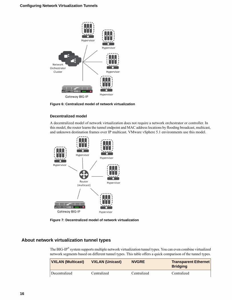
Figure 6: Centralized model of network virtualization
Decentralized model
A decentralized model of network virtualization does not require a network orchestrator or controller. Inthis model, the router learns the tunnel endpoint andMAC address locations by flooding broadcast, multicast,and unknown destination frames over IP multicast. VMware vSphere 5.1 environments use this model.
Figure 7: Decentralized model of network virtualization
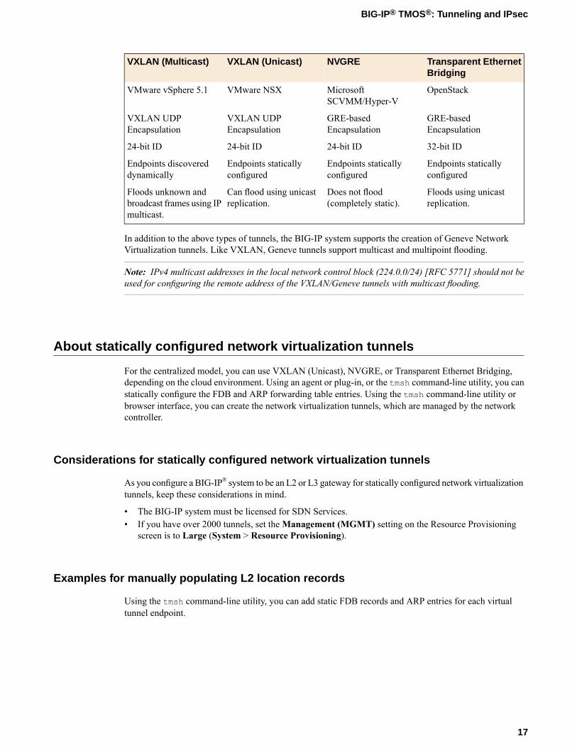
About network virtualization tunnel types
The BIG-IP® system supports multiple network virtualization tunnel types. You can even combine virtualizednetwork segments based on different tunnel types. This table offers a quick comparison of the tunnel types.
Transparent EthernetBridging
NVGREVXLAN (Unicast)VXLAN (Multicast)
CentralizedCentralizedCentralizedDecentralized
16
Configuring Network Virtualization Tunnels
Transparent EthernetBridging
NVGREVXLAN (Unicast)VXLAN (Multicast)
OpenStackMicrosoftSCVMM/Hyper-V
VMware NSXVMware vSphere 5.1
GRE-basedEncapsulation
GRE-basedEncapsulation
VXLAN UDPEncapsulation
VXLAN UDPEncapsulation
32-bit ID24-bit ID24-bit ID24-bit ID
Endpoints staticallyconfigured
Endpoints staticallyconfigured
Endpoints staticallyconfigured
Endpoints discovereddynamically
Floods using unicastreplication.
Does not flood(completely static).
Can flood using unicastreplication.
Floods unknown andbroadcast frames using IPmulticast.
In addition to the above types of tunnels, the BIG-IP system supports the creation of Geneve NetworkVirtualization tunnels. Like VXLAN, Geneve tunnels support multicast and multipoint flooding.
Note: IPv4 multicast addresses in the local network control block (224.0.0/24) [RFC 5771] should not beused for configuring the remote address of the VXLAN/Geneve tunnels with multicast flooding.
About statically configured network virtualization tunnels
For the centralized model, you can use VXLAN (Unicast), NVGRE, or Transparent Ethernet Bridging,depending on the cloud environment. Using an agent or plug-in, or the tmsh command-line utility, you canstatically configure the FDB and ARP forwarding table entries. Using the tmsh command-line utility orbrowser interface, you can create the network virtualization tunnels, which are managed by the networkcontroller.
Considerations for statically configured network virtualization tunnels
As you configure a BIG-IP® system to be an L2 or L3 gateway for statically configured network virtualizationtunnels, keep these considerations in mind.
• The BIG-IP system must be licensed for SDN Services.• If you have over 2000 tunnels, set theManagement (MGMT) setting on the Resource Provisioning
screen is to Large (System > Resource Provisioning).
Examples for manually populating L2 location records
Using the tmsh command-line utility, you can add static FDB records and ARP entries for each virtualtunnel endpoint.
17
BIG-IP® TMOS®: Tunneling and IPsec
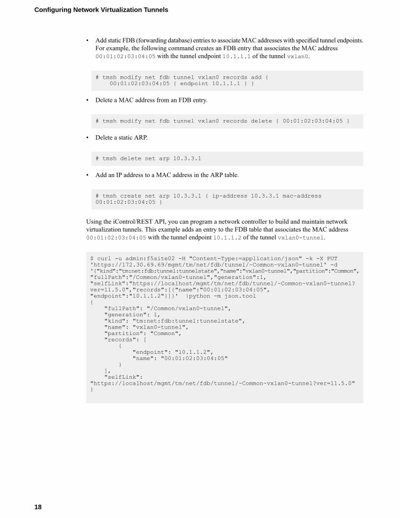
• Add static FDB (forwarding database) entries to associateMAC addresses with specified tunnel endpoints.For example, the following command creates an FDB entry that associates the MAC address00:01:02:03:04:05 with the tunnel endpoint 10.1.1.1 of the tunnel vxlan0.
# tmsh modify net fdb tunnel vxlan0 records add {00:01:02:03:04:05 { endpoint 10.1.1.1 } }
• Delete a MAC address from an FDB entry.
# tmsh modify net fdb tunnel vxlan0 records delete { 00:01:02:03:04:05 }
• Delete a static ARP.
# tmsh delete net arp 10.3.3.1
• Add an IP address to a MAC address in the ARP table.
# tmsh create net arp 10.3.3.1 { ip-address 10.3.3.1 mac-address00:01:02:03:04:05 }
Using the iControl/REST API, you can program a network controller to build and maintain networkvirtualization tunnels. This example adds an entry to the FDB table that associates the MAC address00:01:02:03:04:05 with the tunnel endpoint 10.1.1.2 of the tunnel vxlan0-tunnel.
$ curl -u admin:f5site02 -H "Content-Type:=application/json" -k -X PUT'https://172.30.69.69/mgmt/tm/net/fdb/tunnel/~Common~vxlan0-tunnel' -d'{"kind":"tm:net:fdb:tunnel:tunnelstate","name":"vxlan0-tunnel","partition":"Common","fullPath":"/Common/vxlan0-tunnel","generation":1,"selfLink":"https://localhost/mgmt/tm/net/fdb/tunnel/~Common~vxlan0-tunnel?ver=11.5.0","records":[{"name":"00:01:02:03:04:05","endpoint":"10.1.1.2"}]}' |python -m json.tool{
"fullPath": "/Common/vxlan0-tunnel","generation": 1,"kind": "tm:net:fdb:tunnel:tunnelstate","name": "vxlan0-tunnel","partition": "Common","records": [
{"endpoint": "10.1.1.2","name": "00:01:02:03:04:05"
}],"selfLink":
"https://localhost/mgmt/tm/net/fdb/tunnel/~Common~vxlan0-tunnel?ver=11.5.0"}
18
Configuring Network Virtualization Tunnels
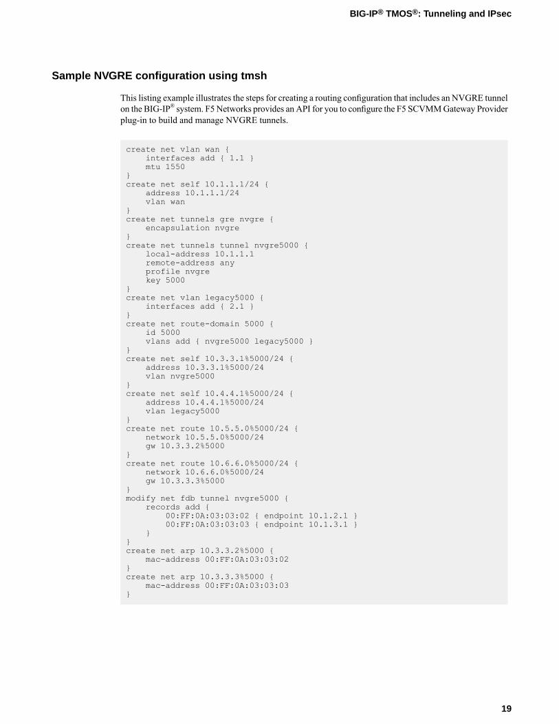
Sample NVGRE configuration using tmsh
This listing example illustrates the steps for creating a routing configuration that includes an NVGRE tunnelon the BIG-IP® system. F5Networks provides an API for you to configure the F5 SCVMMGateway Providerplug-in to build and manage NVGRE tunnels.
create net vlan wan {interfaces add { 1.1 }mtu 1550
}create net self 10.1.1.1/24 {
address 10.1.1.1/24vlan wan
}create net tunnels gre nvgre {
encapsulation nvgre}create net tunnels tunnel nvgre5000 {
local-address 10.1.1.1remote-address anyprofile nvgrekey 5000
}create net vlan legacy5000 {
interfaces add { 2.1 }}create net route-domain 5000 {
id 5000vlans add { nvgre5000 legacy5000 }
}create net self 10.3.3.1%5000/24 {
address 10.3.3.1%5000/24vlan nvgre5000
}create net self 10.4.4.1%5000/24 {
address 10.4.4.1%5000/24vlan legacy5000
}create net route 10.5.5.0%5000/24 {
network 10.5.5.0%5000/24gw 10.3.3.2%5000
}create net route 10.6.6.0%5000/24 {
network 10.6.6.0%5000/24gw 10.3.3.3%5000
}modify net fdb tunnel nvgre5000 {
records add {00:FF:0A:03:03:02 { endpoint 10.1.2.1 }00:FF:0A:03:03:03 { endpoint 10.1.3.1 }
}}create net arp 10.3.3.2%5000 {
mac-address 00:FF:0A:03:03:02}create net arp 10.3.3.3%5000 {
mac-address 00:FF:0A:03:03:03}
19
BIG-IP® TMOS®: Tunneling and IPsec
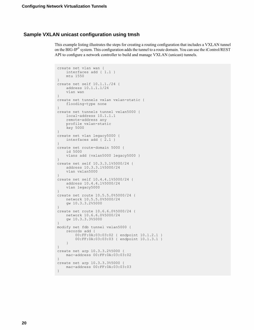
Sample VXLAN unicast configuration using tmsh
This example listing illustrates the steps for creating a routing configuration that includes a VXLAN tunnelon the BIG-IP® system. This configuration adds the tunnel to a route domain. You can use the iControl/RESTAPI to configure a network controller to build and manage VXLAN (unicast) tunnels.
create net vlan wan {interfaces add { 1.1 }mtu 1550
}create net self 10.1.1./24 {
address 10.1.1.1/24vlan wan
}create net tunnels vxlan vxlan-static {
flooding-type none}create net tunnels tunnel vxlan5000 {
local-address 10.1.1.1remote-address anyprofile vxlan-statickey 5000
}create net vlan legacy5000 {
interfaces add { 2.1 }}create net route-domain 5000 {
id 5000vlans add {vxlan5000 legacy5000 }
}create net self 10.3.3.1%5000/24 {
address 10.3.3.1%5000/24vlan vxlan5000
}create net self 10.4.4.1%5000/24 {
address 10.4.4.1%5000/24vlan legacy5000
}create net route 10.5.5.0%5000/24 {
network 10.5.5.0%5000/24gw 10.3.3.2%5000
}create net route 10.6.6.0%5000/24 {
network 10.6.6.0%5000/24gw 10.3.3.3%5000
}modify net fdb tunnel vxlan5000 {
records add {00:FF:0A:03:03:02 { endpoint 10.1.2.1 }00:FF:0A:03:03:03 { endpoint 10.1.3.1 }
}}create net arp 10.3.3.2%5000 {
mac-address 00:FF:0A:03:03:02}create net arp 10.3.3.3%5000 {
mac-address 00:FF:0A:03:03:03}
20
Configuring Network Virtualization Tunnels
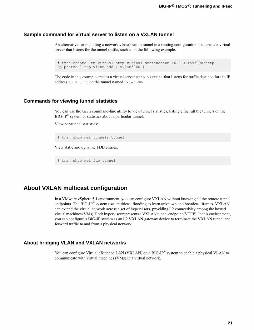
Sample command for virtual server to listen on a VXLAN tunnel
An alternative for including a network virtualization tunnel in a routing configuration is to create a virtualserver that listens for the tunnel traffic, such as in the following example.
# tmsh create ltm virtual http_virtual destination 10.3.3.15%5000:httpip-protocol tcp vlans add { vxlan5000 }
The code in this example creates a virtual server http_virtual that listens for traffic destined for the IPaddress 10.3.3.15 on the tunnel named vxlan5000.
Commands for viewing tunnel statistics
You can use the tmsh command-line utility to view tunnel statistics, listing either all the tunnels on theBIG-IP® system or statistics about a particular tunnel.
View per-tunnel statistics:
# tmsh show net tunnels tunnel
View static and dynamic FDB entries:
# tmsh show net fdb tunnel
About VXLAN multicast configuration
In a VMware vSphere 5.1 environment, you can configure VXLAN without knowing all the remote tunnelendpoints. The BIG-IP® system uses multicast flooding to learn unknown and broadcast frames. VXLANcan extend the virtual network across a set of hypervisors, providing L2 connectivity among the hostedvirtual machines (VMs). Each hypervisor represents a VXLAN tunnel endpoint (VTEP). In this environment,you can configure a BIG-IP system as an L2 VXLAN gateway device to terminate the VXLAN tunnel andforward traffic to and from a physical network.
About bridging VLAN and VXLAN networks
You can configure Virtual eXtended LAN (VXLAN) on a BIG-IP® system to enable a physical VLAN tocommunicate with virtual machines (VMs) in a virtual network.
21
BIG-IP® TMOS®: Tunneling and IPsec
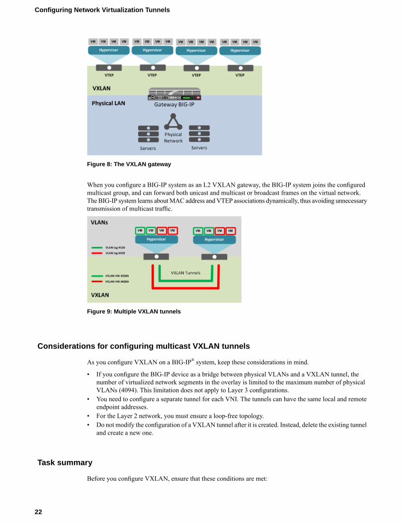
Figure 8: The VXLAN gateway
When you configure a BIG-IP system as an L2 VXLAN gateway, the BIG-IP system joins the configuredmulticast group, and can forward both unicast and multicast or broadcast frames on the virtual network.The BIG-IP system learns aboutMAC address andVTEP associations dynamically, thus avoiding unnecessarytransmission of multicast traffic.
Figure 9: Multiple VXLAN tunnels
Considerations for configuring multicast VXLAN tunnels
As you configure VXLAN on a BIG-IP® system, keep these considerations in mind.
• If you configure the BIG-IP device as a bridge between physical VLANs and a VXLAN tunnel, thenumber of virtualized network segments in the overlay is limited to the maximum number of physicalVLANs (4094). This limitation does not apply to Layer 3 configurations.
• You need to configure a separate tunnel for each VNI. The tunnels can have the same local and remoteendpoint addresses.
• For the Layer 2 network, you must ensure a loop-free topology.• Do not modify the configuration of a VXLAN tunnel after it is created. Instead, delete the existing tunnel
and create a new one.
Task summary
Before you configure VXLAN, ensure that these conditions are met:
22
Configuring Network Virtualization Tunnels
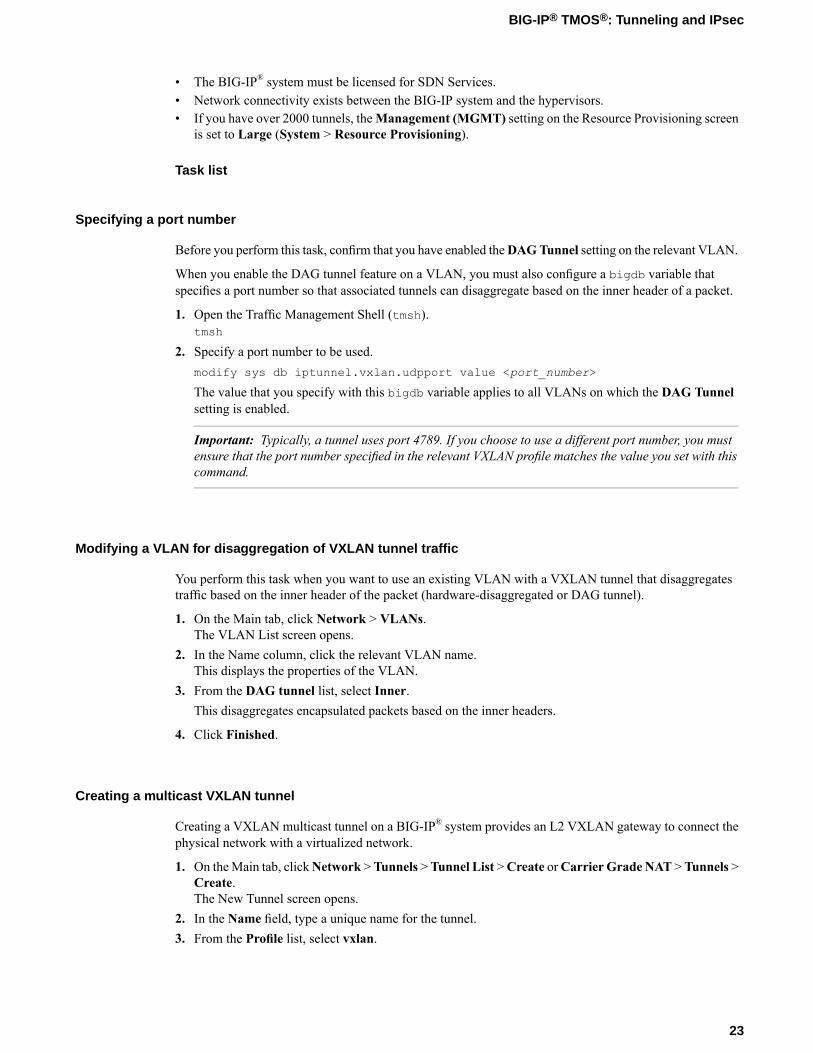
• The BIG-IP® system must be licensed for SDN Services.• Network connectivity exists between the BIG-IP system and the hypervisors.• If you have over 2000 tunnels, theManagement (MGMT) setting on the Resource Provisioning screen
is set to Large (System > Resource Provisioning).
Task list
Specifying a port number
Before you perform this task, confirm that you have enabled theDAGTunnel setting on the relevant VLAN.
When you enable the DAG tunnel feature on a VLAN, you must also configure a bigdb variable thatspecifies a port number so that associated tunnels can disaggregate based on the inner header of a packet.
1. Open the Traffic Management Shell (tmsh).tmsh
2. Specify a port number to be used.modify sys db iptunnel.vxlan.udpport value <port_number>
The value that you specify with this bigdb variable applies to all VLANs on which the DAG Tunnelsetting is enabled.
Important: Typically, a tunnel uses port 4789. If you choose to use a different port number, you mustensure that the port number specified in the relevant VXLAN profile matches the value you set with thiscommand.
Modifying a VLAN for disaggregation of VXLAN tunnel traffic
You perform this task when you want to use an existing VLAN with a VXLAN tunnel that disaggregatestraffic based on the inner header of the packet (hardware-disaggregated or DAG tunnel).
1. On the Main tab, click Network > VLANs.The VLAN List screen opens.
2. In the Name column, click the relevant VLAN name.This displays the properties of the VLAN.
3. From the DAG tunnel list, select Inner.This disaggregates encapsulated packets based on the inner headers.
4. Click Finished.
Creating a multicast VXLAN tunnel
Creating a VXLAN multicast tunnel on a BIG-IP® system provides an L2 VXLAN gateway to connect thephysical network with a virtualized network.
1. On theMain tab, clickNetwork >Tunnels >Tunnel List >Create orCarrier Grade NAT >Tunnels >Create.The New Tunnel screen opens.
2. In the Name field, type a unique name for the tunnel.3. From the Profile list, select vxlan.
23
BIG-IP® TMOS®: Tunneling and IPsec
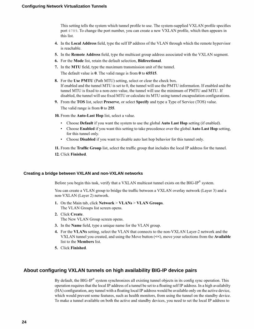
This setting tells the system which tunnel profile to use. The system-supplied VXLAN profile specifiesport 4789. To change the port number, you can create a new VXLAN profile, which then appears inthis list.
4. In the Local Address field, type the self IP address of the VLAN through which the remote hypervisoris reachable.
5. In the Remote Address field, type the multicast group address associated with the VXLAN segment.6. For theMode list, retain the default selection, Bidirectional.7. In theMTU field, type the maximum transmission unit of the tunnel.
The default value is 0. The valid range is from 0 to 65515.
8. For the Use PMTU (Path MTU) setting, select or clear the check box.If enabled and the tunnel MTU is set to 0, the tunnel will use the PMTU information. If enabled and thetunnel MTU is fixed to a non-zero value, the tunnel will use the minimum of PMTU and MTU. Ifdisabled, the tunnel will use fixedMTU or calculate its MTU using tunnel encapsulation configurations.
9. From the TOS list, select Preserve, or select Specify and type a Type of Service (TOS) value.The valid range is from 0 to 255.
10. From the Auto-Last Hop list, select a value.
• Choose Default if you want the system to use the global Auto Last Hop setting (if enabled).• Choose Enabled if you want this setting to take precedence over the global Auto Last Hop setting,
for this tunnel only.• Choose Disabled if you want to disable auto last hop behavior for this tunnel only.
11. From the Traffic Group list, select the traffic group that includes the local IP address for the tunnel.12. Click Finished.
Creating a bridge between VXLAN and non-VXLAN networks
Before you begin this task, verify that a VXLAN multicast tunnel exists on the BIG-IP® system.
You can create a VLAN group to bridge the traffic between a VXLAN overlay network (Layer 3) and anon-VXLAN (Layer 2) network.
1. On the Main tab, click Network > VLANs > VLAN Groups.The VLAN Groups list screen opens.
2. Click Create.The New VLAN Group screen opens.
3. In the Name field, type a unique name for the VLAN group.4. For the VLANs setting, select the VLAN that connects to the non-VXLAN Layer-2 network and the
VXLAN tunnel you created, and using the Move button (<<), move your selections from the Availablelist to theMembers list.
5. Click Finished.
About configuring VXLAN tunnels on high availability BIG-IP device pairs
By default, the BIG-IP® system synchronizes all existing tunnel objects in its config sync operation. Thisoperation requires that the local IP address of a tunnel be set to a floating self IP address. In a high availabilty(HA) configuration, any tunnel with a floating local IP address would be available only on the active device,which would prevent some features, such as health monitors, from using the tunnel on the standby device.To make a tunnel available on both the active and standby devices, you need to set the local IP address to
24
Configuring Network Virtualization Tunnels

a non-floating self IP address, which then requires that you exclude tunnels from the config sync operation.To disable the synchronization of tunnel objects, you can set a bigdb variable on both devices.
Disabling config sync for tunnels
In certain cases, you might want to disable config sync behavior for tunnels, such as when you need to makeVXLAN tunnels functional on all devices in a BIG-IP® device group configured for high availability. Thetunnel config sync setting applies to all tunnels created on the BIG-IP device.
Important: Disable config sync on both the active and standby devices before you create any tunnels.
1. Log in to thetmsh command-line utility for the BIG-IP system.2. Determine whether the variable is already disabled, by typing this command.
tmsh list sys db iptunnel.configsync value
3. Disable the variable.tmsh modify sys db iptunnel.configsync value disable
4. Save the configuration.tmsh save sys config
5. F5 recommends that you reboot both the active and standby devices.
Now you can create tunnels with non-floating local IP addresses on both the active and standby devices.
About configuring VXLAN tunnels using OVSDB
You can configure the OVSDB management component of the BIG-IP® system to create VXLAN tunnelsusing an SDN controller. SDNControllers use the OVSDB (Open vSwitch Database) management protocolto pass overlay configuration information to hypervisors and gateways. The BIG-IP system supports usingthe Hardware VTEP schemawith the OVSDBmanagement protocol to communicate with OVSDB-capablecontrollers. The system uses the OVSDB management component to set up this communication. After theBIG-IP system establishes communication with an OVSDB controller, it can begin to receive tunnel endpointconfiguration information. The system uses this information to create VXLAN tunnel objects and theirassociated FDB entries. The created objects allow the system to communicate with other VXLAN endpointsin an overlay segment.
Setting up the OVSDB management component
You can set up the OVSDB management component to communicate with OVSDB-capable controllers tocreate VXLAN tunnel objects.
1. On the Main tab, click System > Configuration > OVSDB.2. From the OVSDB list, select Enable.3. In the Controller Addresses field, type an OVSDB-capable controller IP address and click Add.
If the BIG-IP system is communicating with a controller cluster, repeat this step for each controller IPaddress.
4. In the Tunnel Local Address field, type the IP address of the local endpoint of the tunnel.
25
BIG-IP® TMOS®: Tunneling and IPsec
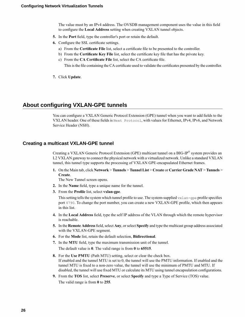
The value must by an IPv4 address. The OVSDB management component uses the value in this fieldto configure the Local Address setting when creating VXLAN tunnel objects.
5. In the Port field, type the controller's port or retain the default.6. Configure the SSL certificate settings.
a) From the Certificate File list, select a certificate file to be presented to the controller.b) From the Certificate Key File list, select the certificate key file that has the private key.c) From the CA Certificate File list, select the CA certificate file.
This is the file containing the CA certificate used to validate the certificates presented by the controller.
7. Click Update.
About configuring VXLAN-GPE tunnels
You can configure a VXLAN Generic Protocol Extension (GPE) tunnel when you want to add fields to theVXLAN header. One of these fields is Next Protocol, with values for Ethernet, IPv4, IPv6, and NetworkService Header (NSH).
Creating a multicast VXLAN-GPE tunnel
Creating a VXLAN Generic Protocol Extension (GPE) multicast tunnel on a BIG-IP® system provides anL2 VXLAN gateway to connect the physical network with a virtualized network. Unlike a standard VXLANtunnel, this tunnel type supports the processing of VXLAN GPE-encapsulated Ethernet frames.
1. On theMain tab, clickNetwork >Tunnels >Tunnel List >Create orCarrier Grade NAT >Tunnels >Create.The New Tunnel screen opens.
2. In the Name field, type a unique name for the tunnel.3. From the Profile list, select vxlan-gpe.
This setting tells the systemwhich tunnel profile to use. The system-supplied vxlan-gpe profile specifiesport 4790. To change the port number, you can create a new VXLAN-GPE profile, which then appearsin this list.
4. In the Local Address field, type the self IP address of the VLAN through which the remote hypervisoris reachable.
5. In theRemote Address field, selectAny, or select Specify and type themulticast group address associatedwith the VXLAN-GPE segment.
6. For theMode list, retain the default selection, Bidirectional.7. In theMTU field, type the maximum transmission unit of the tunnel.
The default value is 0. The valid range is from 0 to 65515.
8. For the Use PMTU (Path MTU) setting, select or clear the check box.If enabled and the tunnel MTU is set to 0, the tunnel will use the PMTU information. If enabled and thetunnel MTU is fixed to a non-zero value, the tunnel will use the minimum of PMTU and MTU. Ifdisabled, the tunnel will use fixedMTU or calculate its MTU using tunnel encapsulation configurations.
9. From the TOS list, select Preserve, or select Specify and type a Type of Service (TOS) value.The valid range is from 0 to 255.
26
Configuring Network Virtualization Tunnels

10. From the Auto-Last Hop list, select a value.
• Choose Default if you want the system to use the global Auto Last Hop setting (if enabled).• Choose Enabled if you want this setting to take precedence over the global Auto Last Hop setting,
for this tunnel only.• Choose Disabled if you want to disable auto last hop behavior for this tunnel only.
11. From the Traffic Group list, select the traffic group that includes the local IP address for the tunnel.12. Click Finished.
27
BIG-IP® TMOS®: Tunneling and IPsec

Configuring NVGRE Tunnels for HA-Paired Devices
Overview: Configuring NVGRE tunnels for HA-paired devices
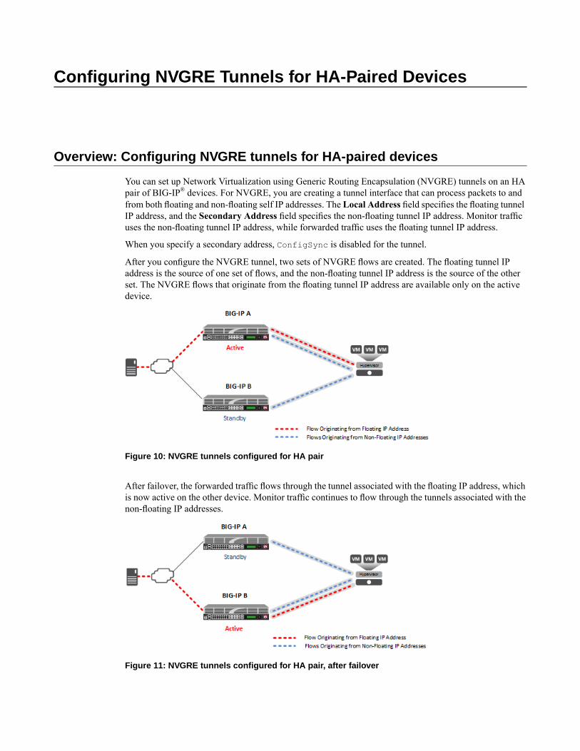
You can set up Network Virtualization using Generic Routing Encapsulation (NVGRE) tunnels on an HApair of BIG-IP® devices. For NVGRE, you are creating a tunnel interface that can process packets to andfrom both floating and non-floating self IP addresses. The Local Address field specifies the floating tunnelIP address, and the Secondary Address field specifies the non-floating tunnel IP address. Monitor trafficuses the non-floating tunnel IP address, while forwarded traffic uses the floating tunnel IP address.
When you specify a secondary address, ConfigSync is disabled for the tunnel.
After you configure the NVGRE tunnel, two sets of NVGRE flows are created. The floating tunnel IPaddress is the source of one set of flows, and the non-floating tunnel IP address is the source of the otherset. The NVGRE flows that originate from the floating tunnel IP address are available only on the activedevice.
Figure 10: NVGRE tunnels configured for HA pair
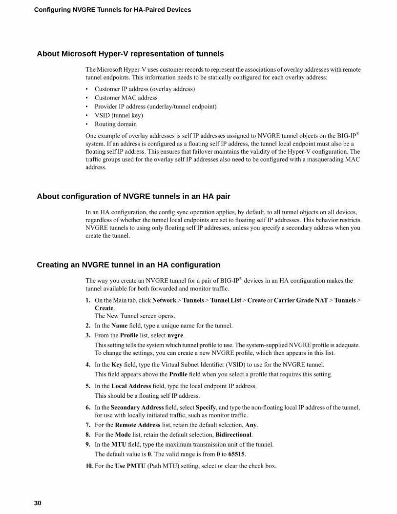
After failover, the forwarded traffic flows through the tunnel associated with the floating IP address, whichis now active on the other device. Monitor traffic continues to flow through the tunnels associated with thenon-floating IP addresses.
Figure 11: NVGRE tunnels configured for HA pair, after failover
About Microsoft Hyper-V representation of tunnels
TheMicrosoft Hyper-V uses customer records to represent the associations of overlay addresses with remotetunnel endpoints. This information needs to be statically configured for each overlay address:
• Customer IP address (overlay address)• Customer MAC address• Provider IP address (underlay/tunnel endpoint)• VSID (tunnel key)• Routing domain
One example of overlay addresses is self IP addresses assigned to NVGRE tunnel objects on the BIG-IP®
system. If an address is configured as a floating self IP address, the tunnel local endpoint must also be afloating self IP address. This ensures that failover maintains the validity of the Hyper-V configuration. Thetraffic groups used for the overlay self IP addresses also need to be configured with a masquerading MACaddress.
About configuration of NVGRE tunnels in an HA pair
In an HA configuration, the config sync operation applies, by default, to all tunnel objects on all devices,regardless of whether the tunnel local endpoints are set to floating self IP addresses. This behavior restrictsNVGRE tunnels to using only floating self IP addresses, unless you specify a secondary address when youcreate the tunnel.
Creating an NVGRE tunnel in an HA configuration
The way you create an NVGRE tunnel for a pair of BIG-IP® devices in an HA configuration makes thetunnel available for both forwarded and monitor traffic.
1. On theMain tab, clickNetwork >Tunnels >Tunnel List >Create orCarrier Grade NAT >Tunnels >Create.The New Tunnel screen opens.
2. In the Name field, type a unique name for the tunnel.3. From the Profile list, select nvgre.
This setting tells the systemwhich tunnel profile to use. The system-supplied NVGRE profile is adequate.To change the settings, you can create a new NVGRE profile, which then appears in this list.
4. In the Key field, type the Virtual Subnet Identifier (VSID) to use for the NVGRE tunnel.This field appears above the Profile field when you select a profile that requires this setting.
5. In the Local Address field, type the local endpoint IP address.This should be a floating self IP address.
6. In the Secondary Address field, select Specify, and type the non-floating local IP address of the tunnel,for use with locally initiated traffic, such as monitor traffic.
7. For the Remote Address list, retain the default selection, Any.8. For theMode list, retain the default selection, Bidirectional.9. In theMTU field, type the maximum transmission unit of the tunnel.
The default value is 0. The valid range is from 0 to 65515.
10. For the Use PMTU (Path MTU) setting, select or clear the check box.
30
Configuring NVGRE Tunnels for HA-Paired Devices
If enabled and the tunnel MTU is set to 0, the tunnel will use the PMTU information. If enabled and thetunnel MTU is fixed to a non-zero value, the tunnel will use the minimum of PMTU and MTU. Ifdisabled, the tunnel will use fixedMTU or calculate its MTU using tunnel encapsulation configurations.
11. From the TOS list, select Preserve, or select Specify and type a Type of Service (TOS) value.The valid range is from 0 to 255.
12. From the Auto-Last Hop list, select a value.
• Choose Default if you want the system to use the global Auto Last Hop setting (if enabled).• Choose Enabled if you want this setting to take precedence over the global Auto Last Hop setting,
for this tunnel only.• Choose Disabled if you want to disable auto last hop behavior for this tunnel only.
13. From the Traffic Group list, select the traffic group that includes the local IP address for the tunnel.14. Click Finished.
31
BIG-IP® TMOS®: Tunneling and IPsec

Configuring the BIG-IP System as an HNV Gateway
Overview: Using the BIG-IP system as a Hyper-V Network Virtualizationgateway
You can set up the BIG-IP® system to be an NVGRE gateway from aMicrosoft Hyper-V virtualized networkto external networks, and to provide services within the virtualized network. Each Hyper-V NetworkVirtualization (HNV) routing domain requires a number of per-subnet (VSID) NVGRE tunnels. For eachHNV routing domain, you need to create a single, inbound-only tunnel with special inbound packetprocessing. Inbound NVGRE tunnels process traffic that was forwarded by HNV distributed routers, whichuse a special VSID to forward all routed packets to a gateway. Packets received from the inbound tunnelare internally remapped to the correct per-subnet tunnel. Thus, all decapsulated packets appear to be arrivingonly from the correct per-subnet tunnel.
Creating per-subnet tunnels for Hyper-V Network Virtualization routing domains.
You can configure an NVGRE inbound-only tunnel when you are using the BIG-IP® system as a gatewaybetween Microsoft Hyper-V Network Virtualization networks and external networks.
1. On theMain tab, clickNetwork >Tunnels >Tunnel List >Create orCarrier Grade NAT >Tunnels >Create.The New Tunnel screen opens.
2. In the Name field, type a unique name for the tunnel.3. From the Profile list, select nvgre.
This setting tells the systemwhich tunnel profile to use. The system-supplied NVGRE profile is adequate.To change the settings, you can create a new NVGRE profile, which then appears in this list.
4. In the Key field, type the special Virtual Subnet Identifier (VSID) that is used by Hyper-V NetworkVirtualization distributed routers to forward all routed packets to a gateway.This field appears above the Profile field when you select a profile that requires this setting.
5. In the Local Address field, type the local endpoint IP address.This should be a floating self IP address.
6. In the Secondary Address field, select Specify, and type the non-floating local IP address of the tunnel.7. For the Remote Address list, retain the default selection, Any.8. From theMode list, select Inbound.9. From the Traffic Group list, select the traffic group that includes the local IP address for the tunnel.10. Click Finished.
If you are using the BIG-IP system as a gateway, the preferred method is to install the F5 Networks HNVGateway PowerShell Module in the System Center Virtual Machine Manager (SCVMM) for integrationinto a Microsoft Hyper-V environment.

Configuring an EtherIP Tunnel
Overview: Preserving BIG-IP connections during live virtual machinemigration
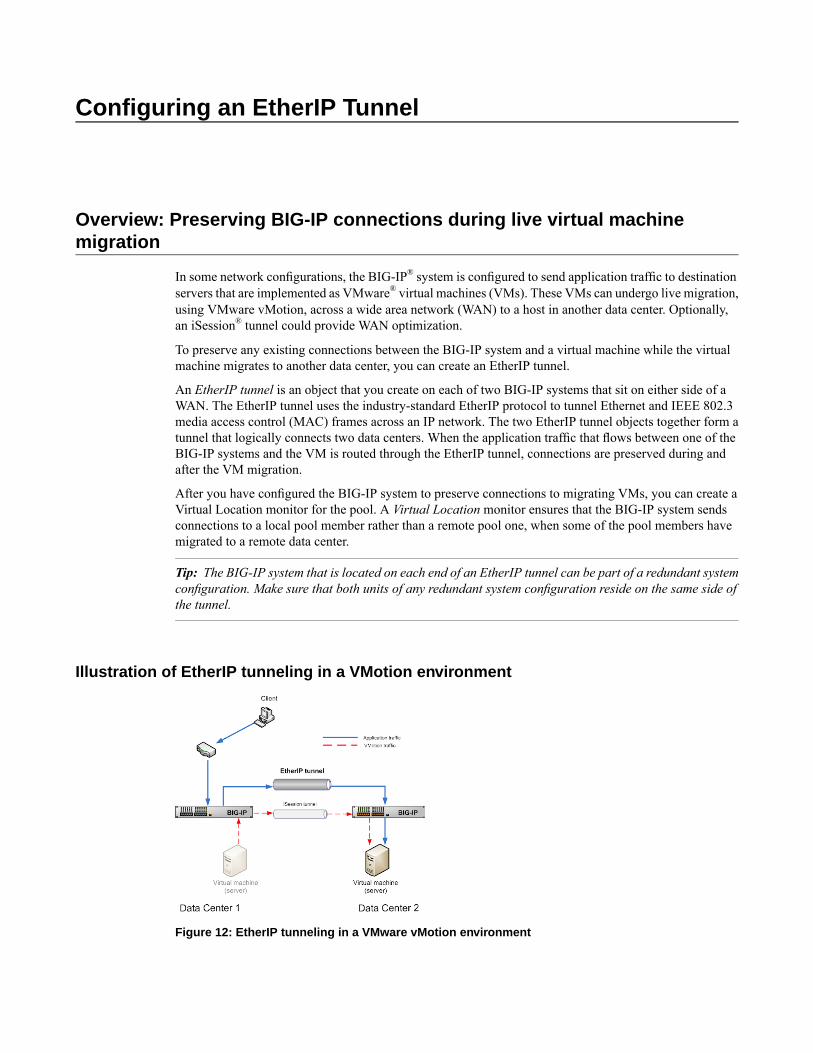
In some network configurations, the BIG-IP® system is configured to send application traffic to destinationservers that are implemented as VMware® virtual machines (VMs). These VMs can undergo live migration,using VMware vMotion, across a wide area network (WAN) to a host in another data center. Optionally,an iSession® tunnel could provide WAN optimization.
To preserve any existing connections between the BIG-IP system and a virtual machine while the virtualmachine migrates to another data center, you can create an EtherIP tunnel.
An EtherIP tunnel is an object that you create on each of two BIG-IP systems that sit on either side of aWAN. The EtherIP tunnel uses the industry-standard EtherIP protocol to tunnel Ethernet and IEEE 802.3media access control (MAC) frames across an IP network. The two EtherIP tunnel objects together form atunnel that logically connects two data centers. When the application traffic that flows between one of theBIG-IP systems and the VM is routed through the EtherIP tunnel, connections are preserved during andafter the VM migration.
After you have configured the BIG-IP system to preserve connections to migrating VMs, you can create aVirtual Location monitor for the pool. A Virtual Location monitor ensures that the BIG-IP system sendsconnections to a local pool member rather than a remote pool one, when some of the pool members havemigrated to a remote data center.
Tip: The BIG-IP system that is located on each end of an EtherIP tunnel can be part of a redundant systemconfiguration. Make sure that both units of any redundant system configuration reside on the same side ofthe tunnel.
Illustration of EtherIP tunneling in a VMotion environment
Figure 12: EtherIP tunneling in a VMware vMotion environment
Task summary
Implement an EtherIP tunneling configuration to prevent the BIG-IP® system from dropping existingconnections to migrating virtual machines in a VMware VMotion environment.
Important: Perform these tasks on the BIG-IP system in both the local data center and the remote datacenter.
Task List
Creating a VLAN
VLANs represent a logical collection of hosts that can share network resources, regardless of their physicallocation on the network. You create a VLAN to associate physical interfaces with traffic destined for aspecific address space. For the most basic BIG-IP® system configuration with redundancy enabled, youtypically create multiple VLANs. That is, you create a VLAN for each of the internal and external networks,as well as a VLAN for high availability communications. If your hardware platform supports ePVA, youhave the additional option of configuring double tagging (also known as Q-in-Q tagging) for a VLAN.
1. On the Main tab, click Network > VLANs.The VLAN List screen opens.
2. Click Create.The New VLAN screen opens.
3. In the Name field, type a unique name for the VLAN.4. In the Tag field, type a numeric tag, between 1-4094, for the VLAN, or leave the field blank if you want
the BIG-IP system to automatically assign a VLAN tag.The VLAN tag identifies the traffic from hosts in the associated VLAN.
5. From the Customer Tag list:a) Retain the default value of None or select Specify.b) If you chose Specify in the previous step, type a numeric tag, between 1-4094, for the VLAN.
The customer tag specifies the inner tag of any frame passing through the VLAN.
6. For the Interfaces setting:a) From the Interface list, select an interface number or trunk name.b) From the Tagging list, select Tagged or Untagged.
Select Tagged when you want traffic for that interface to be tagged with a VLAN ID.
c) If you specified a numeric value for theCustomer Tag setting and from theTagging list you selectedTagged, then from the Tag Mode list, select a value.
d) Click Add.e) Repeat these steps for each interface or trunk that you want to assign to the VLAN.
7. If you want the system to verify that the return route to an initial packet is the same VLAN from whichthe packet originated, select the Source Check check box.
8. In theMTU field, retain the default number of bytes (1500).9. From the Configuration list, select Advanced.10. If you want to base redundant-system failover on VLAN-related events, select the Fail-safe check box.
36
Configuring an EtherIP Tunnel
11. From the Auto Last Hop list, select a value.12. From the CMP Hash list, select a value.13. To enable the DAG Round Robin setting, select the check box.14. Configure the sFlow settings or retain the default values.15. Click Finished.
The screen refreshes, and displays the new VLAN in the list.
After you create the VLAN, you can assign the VLAN to a self IP address.
After creating the VLAN, ensure that you repeat this task to create as many VLANs as needed.
Creating an EtherIP tunnel object
Before you perform this task, you must know the self IP address of the instance of the VLAN that exists,or will exist, on the BIG-IP® system in the other data center.
The purpose of an EtherIP tunnel that contains an EtherIP type of profile is to enable the BIG-IP system topreserve any current connections to a server that is using VMware vMotion for migration to another datacenter.
1. On the Main tab, click Network > Tunnels > Tunnel List > Create.The New Tunnel screen opens.
2. In the Name field, type a unique name for the tunnel.3. From the Profile list, select etherip.4. In the Local Address field, type the self IP address of the local BIG-IP system.5. In the Remote Address field, type the self IP address of the remote BIG-IP system.6. If the BIG-IP system is part of an HA cluster, select the corresponding traffic group from the Traffic
Group list.7. Click Finished.
Creating a VLAN group
VLAN groups consolidate Layer 2 traffic from two or more separate VLANs.
1. On the Main tab, click Network > VLANs > VLAN Groups.The VLAN Groups list screen opens.
2. Click Create.The New VLAN Group screen opens.
3. In the Name field, type a unique name for the VLAN group.4. For theVLANs setting, select the EtherIP tunnel that you created (which appears in the VLAN list) and
the VLAN that connects to the host where the VMs exist, and using the Move button (<<), move yourselections from the Available list to theMembers list.
5. From the Transparency Mode list, select Transparent.6. Select the Bridge All Traffic check box if you want the VLAN group to forward all frames, including
non-IP traffic.The default setting is disabled (not selected).
7. Select the Bridge in Standby check box if you want the VLAN group to forward frames, even whenthe system is the standby unit of a redundant system.
37
BIG-IP® TMOS®: Tunneling and IPsec
8. Click Finished.
Creating a self IP address
Before you create a self IP address, ensure that you have created a VLAN that you can associate with theself IP address.
A self IP address enables the BIG-IP® system and other devices on the network to route application trafficthrough the associated VLAN or VLAN group. When you do not intend to provision the vCMP® feature,you typically create self IP addresses when you initially configure the BIG-IP system on the VIPRION®
platform.
If you plan to provision vCMP, however, you do not need to create self IP addresses during initial BIG-IPsystem configuration. Instead, the host administrator creates VLANs for use by guests, and the guestadministrators create self IP addresses to associate with those VLANs.
1. On the Main tab, click Network > Self IPs.2. Click Create.
The New Self IP screen opens.3. In the Name field, type a unique name for the self IP address.4. In the IP Address field, type an IPv4 or IPv6 address.
This IP address should represent the address space of the VLAN that you specify with theVLAN/Tunnelsetting.
5. In the Netmask field, type the full network mask for the specified IP address.6. From the VLAN/Tunnel list, select the VLAN to associate with this self IP address.
• On the internal network, select the internal or high availability VLAN that is associated with aninternal interface or trunk.
• On the external network, select the external VLAN that is associated with an external interface ortrunk.
7. From the Port Lockdown list, select Allow Default.8. If the BIG-IP system is part of a redundant system configuration, select the corresponding traffic group
from the Traffic Group list.9. Click Finished.
The screen refreshes, and displays the new self IP address.
After you perform this task, the BIG-IP system can send and receive traffic through the specified VLANor VLAN group. If the self IP address is member of a floating traffic group and you configure the systemfor redundancy, the self IP address can fail over to another device group member if necessary.
Creating a self IP for a VLAN group
Before you create a self IP address, ensure that you have created at least one VLAN group.
You perform this task to create a self IP address for a VLAN group. The self IP address for the VLAN groupprovides a route for packets destined for the network. With the BIG-IP® system, the path to an IP networkis a VLAN. However, with the VLAN group feature used in this procedure, the path to the IP network10.0.0.0 is actually through more than one VLAN. As IP routers are designed to have only one physicalroute to a network, a routing conflict can occur.With a self IP address on the BIG-IP system, you can resolvethe routing conflict by associating a self IP address with the VLAN group.
38
Configuring an EtherIP Tunnel
1. On the Main tab, click Network > Self IPs.2. Click Create.
The New Self IP screen opens.3. In the Name field, type a unique name for the self IP address.4. In the IP Address field, type an IPv4 address.
This IP address should represent the address space of the VLAN group that you specify with theVLAN/Tunnel setting.
5. In the Netmask field, type the network mask for the specified IP address.For this example, type 255.255.255.0.
6. From the VLAN/Tunnel list, select the VLAN group with which to associate this self IP address.7. From the Port Lockdown list, select Allow Default.8. If the BIG-IP system is part of a redundant system configuration, select the corresponding traffic group
from the Traffic Group list.9. Click Finished.
Creating a Virtual Location monitor
When the BIG-IP® system is directing application traffic to pool members that are implemented as virtualmachines, you should configure a Virtual Location type of monitor on the BIG-IP system. A Virtual Locationmonitor determines if a pool member is local to the data center or remote, and assigns a priority group tothe pool member accordingly. Themonitor assigns remote pool members a lower priority than local members,thus ensuring that the BIG-IP directs application requests to local pool members whenever possible.
1. On the Main tab, click Local Traffic >Monitors.The Monitor List screen opens.
2. Click Create.The New Monitor screen opens.
3. Type my_virtual_location_monitor in the Name field.4. From the Type list, select Virtual Location.5. From the Configuration list, select Advanced.6. Retain the default value (in seconds) of 5 in the Interval field.7. Retain the default value of Disabled in the Up Interval list.8. Retain the default value (in seconds) of 0 in the Time Until Up field.9. Retain the default value (in seconds) of 16 in the Timeout field.10. Type the name of the pool that you created prior to configuring EtherIP tunneling in the Pool Name
field.11. Click Finished.
After configuring the Virtual Location monitor, the BIG-IP system assigns each member of the designatedpool a priority group value to ensure that incoming connections are directed to a local pool member wheneverpossible.
F5 Networks recommends that you verify that BIG-IP® DNS has automatically assigned a BIG-IP type ofmonitor to BIG-IP® Local Traffic Manager™ (LTM®). A BIG-IP type of monitor can use the priority groupassigned to each pool member to retrieve a gtm_score value.
39
BIG-IP® TMOS®: Tunneling and IPsec
Syncing the BIG-IP configuration to the device group
Before you sync the configuration, verify that the devices targeted for config sync are members of a devicegroup and that device trust is established.
This task synchronizes the BIG-IP® configuration data from the local device to the devices in the devicegroup. This synchronization ensures that devices in the device group operate properly. When synchronizingself IP addresses, the BIG-IP system synchronizes floating self IP addresses only.
Important: You perform this task on either of the two devices, but not both.
1. On the Main tab, click Device Management > Overview.2. In the Device Groups area of the screen, from the Name column, select the name of the relevant device
group.The screen expands to show a summary and details of the sync status of the selected device group, aswell as a list of the individual devices within the device group.
3. In the Devices area of the screen, from the Sync Status column, select the device that shows a sync statusof Changes Pending.
4. In the Sync Options area of the screen, select Sync Device to Group.5. Click Sync.
The BIG-IP system syncs the configuration data of the selected device in the Device area of the screento the other members of the device group.
After performing this task, all BIG-IP configuration data that is eligible for synchronization to other devicesis replicated on each device in the device group.
Implementation result
After you configure EtherIP tunneling on the BIG-IP system, you must perform the same configurationprocedure on the BIG-IP system in the remote data center to fully establish the EtherIP tunnel.
After the tunnel is established, the BIG-IP system preserves any open connections to migrating (or migrated)virtual machine servers.
40
Configuring an EtherIP Tunnel
Securing EtherIP Tunnel Traffic with IPsec
Overview: Securing EtherIP tunnel traffic with IPsec
You can use the IPsec protocol to secure EtherIP tunnel traffic that is undergoing live migration across awide area network (WAN) using VMware vMotion. The EtherIP tunnel preserves any existing connectionsbetween the BIG-IP® system and a virtual machine while the virtual machine migrates to another data center.Adding IPsec to this configuration involves adding an IPsec traffic selector on each side of the IPsec tunnel.Those traffic selectors have the same source and destination IP addresses as the EtherIP tunnel.
Important: Perform these tasks on the BIG-IP system in both the local data center and the remote datacenter.
Task List
Creating a VLAN
VLANs represent a logical collection of hosts that can share network resources, regardless of their physicallocation on the network. You create a VLAN to associate physical interfaces with traffic destined for aspecific address space. For the most basic BIG-IP® system configuration with redundancy enabled, youtypically create multiple VLANs. That is, you create a VLAN for each of the internal and external networks,as well as a VLAN for high availability communications. If your hardware platform supports ePVA, youhave the additional option of configuring double tagging (also known as Q-in-Q tagging) for a VLAN.
1. On the Main tab, click Network > VLANs.The VLAN List screen opens.
2. Click Create.The New VLAN screen opens.
3. In the Name field, type a unique name for the VLAN.4. In the Tag field, type a numeric tag, between 1-4094, for the VLAN, or leave the field blank if you want
the BIG-IP system to automatically assign a VLAN tag.The VLAN tag identifies the traffic from hosts in the associated VLAN.
5. From the Customer Tag list:a) Retain the default value of None or select Specify.b) If you chose Specify in the previous step, type a numeric tag, between 1-4094, for the VLAN.
The customer tag specifies the inner tag of any frame passing through the VLAN.
6. For the Interfaces setting:a) From the Interface list, select an interface number or trunk name.b) From the Tagging list, select Tagged or Untagged.
Select Tagged when you want traffic for that interface to be tagged with a VLAN ID.
c) If you specified a numeric value for theCustomer Tag setting and from theTagging list you selectedTagged, then from the Tag Mode list, select a value.
d) Click Add.e) Repeat these steps for each interface or trunk that you want to assign to the VLAN.
7. If you want the system to verify that the return route to an initial packet is the same VLAN from whichthe packet originated, select the Source Check check box.
8. In theMTU field, retain the default number of bytes (1500).9. From the Configuration list, select Advanced.10. If you want to base redundant-system failover on VLAN-related events, select the Fail-safe check box.11. From the Auto Last Hop list, select a value.12. From the CMP Hash list, select a value.13. To enable the DAG Round Robin setting, select the check box.14. Configure the sFlow settings or retain the default values.15. Click Finished.
The screen refreshes, and displays the new VLAN in the list.
After you create the VLAN, you can assign the VLAN to a self IP address.
After creating the VLAN, ensure that you repeat this task to create as many VLANs as needed.
Creating an EtherIP tunnel object
Before you perform this task, you must know the self IP address of the instance of the VLAN that exists,or will exist, on the BIG-IP® system in the other data center.
The purpose of an EtherIP tunnel that contains an EtherIP type of profile is to enable the BIG-IP system topreserve any current connections to a server that is using VMware vMotion for migration to another datacenter.
1. On the Main tab, click Network > Tunnels > Tunnel List > Create.The New Tunnel screen opens.
2. In the Name field, type a unique name for the tunnel.3. From the Profile list, select etherip.4. In the Local Address field, type the self IP address of the local BIG-IP system.5. In the Remote Address field, type the self IP address of the remote BIG-IP system.6. If the BIG-IP system is part of an HA cluster, select the corresponding traffic group from the Traffic
Group list.7. Click Finished.
Creating a VLAN group
VLAN groups consolidate Layer 2 traffic from two or more separate VLANs.
1. On the Main tab, click Network > VLANs > VLAN Groups.The VLAN Groups list screen opens.
2. Click Create.The New VLAN Group screen opens.
3. In the Name field, type a unique name for the VLAN group.
42
Securing EtherIP Tunnel Traffic with IPsec
4. For theVLANs setting, select the EtherIP tunnel that you created (which appears in the VLAN list) andthe VLAN that connects to the host where the VMs exist, and using the Move button (<<), move yourselections from the Available list to theMembers list.
5. From the Transparency Mode list, select Transparent.6. Select the Bridge All Traffic check box if you want the VLAN group to forward all frames, including
non-IP traffic.The default setting is disabled (not selected).
7. Select the Bridge in Standby check box if you want the VLAN group to forward frames, even whenthe system is the standby unit of a redundant system.
8. Click Finished.
Creating a self IP address
Before you create a self IP address, ensure that you have created a VLAN that you can associate with theself IP address.
A self IP address enables the BIG-IP® system and other devices on the network to route application trafficthrough the associated VLAN or VLAN group. When you do not intend to provision the vCMP® feature,you typically create self IP addresses when you initially configure the BIG-IP system on the VIPRION®
platform.
If you plan to provision vCMP, however, you do not need to create self IP addresses during initial BIG-IPsystem configuration. Instead, the host administrator creates VLANs for use by guests, and the guestadministrators create self IP addresses to associate with those VLANs.
1. On the Main tab, click Network > Self IPs.2. Click Create.
The New Self IP screen opens.3. In the Name field, type a unique name for the self IP address.4. In the IP Address field, type an IPv4 or IPv6 address.
This IP address should represent the address space of the VLAN that you specify with theVLAN/Tunnelsetting.
5. In the Netmask field, type the full network mask for the specified IP address.6. From the VLAN/Tunnel list, select the VLAN to associate with this self IP address.
• On the internal network, select the internal or high availability VLAN that is associated with aninternal interface or trunk.
• On the external network, select the external VLAN that is associated with an external interface ortrunk.
7. From the Port Lockdown list, select Allow Default.8. If the BIG-IP system is part of a redundant system configuration, select the corresponding traffic group
from the Traffic Group list.9. Click Finished.
The screen refreshes, and displays the new self IP address.
After you perform this task, the BIG-IP system can send and receive traffic through the specified VLANor VLAN group. If the self IP address is member of a floating traffic group and you configure the systemfor redundancy, the self IP address can fail over to another device group member if necessary.
43
BIG-IP® TMOS®: Tunneling and IPsec
Creating a self IP for a VLAN group
Before you create a self IP address, ensure that you have created at least one VLAN group.
You perform this task to create a self IP address for a VLAN group. The self IP address for the VLAN groupprovides a route for packets destined for the network. With the BIG-IP® system, the path to an IP networkis a VLAN. However, with the VLAN group feature used in this procedure, the path to the IP network10.0.0.0 is actually through more than one VLAN. As IP routers are designed to have only one physicalroute to a network, a routing conflict can occur.With a self IP address on the BIG-IP system, you can resolvethe routing conflict by associating a self IP address with the VLAN group.
1. On the Main tab, click Network > Self IPs.2. Click Create.
The New Self IP screen opens.3. In the Name field, type a unique name for the self IP address.4. In the IP Address field, type an IPv4 address.
This IP address should represent the address space of the VLAN group that you specify with theVLAN/Tunnel setting.
5. In the Netmask field, type the network mask for the specified IP address.For this example, type 255.255.255.0.
6. From the VLAN/Tunnel list, select the VLAN group with which to associate this self IP address.7. From the Port Lockdown list, select Allow Default.8. If the BIG-IP system is part of a redundant system configuration, select the corresponding traffic group
from the Traffic Group list.9. Click Finished.
Creating a custom IPsec policy for EtherIP tunnel traffic
When you use IPsec to secure EtherIP tunnel traffic, you must create a custom IPsec policy for the trafficselector to use.
1. On the Main tab, click Network > IPsec > IPsec Policies.2. Click the Create button.
The New Policy screen opens.3. In the Name field, type a unique name for the policy.4. From theMode list, select Tunnel.
The screen refreshes to show additional related settings.5. In the Tunnel Local Address field, type an IP address.
This IP address must match the local address of the EtherIP tunnel and the source IP address of theassociated traffic selector.
6. In the Tunnel Remote Address field, type an IP address.This IP address must match the remote address of the EtherIP tunnel and the destination IP address ofthe associated traffic selector.
7. Click Finished.The screen refreshes and displays the new IPsec policy in the list.
44
Securing EtherIP Tunnel Traffic with IPsec
Creating an IPsec traffic selector for EtherIP traffic
Before you start this task, make sure that you have created a custom IPsec policy to use with this trafficselector.
When you use IPsec to secure EtherIP tunnel traffic, you must create an IPsec traffic selector at each endof the IPsec tunnel to capture the EtherIP traffic.
1. On the Main tab, click Network > IPsec > Traffic Selectors.2. Click Create.
The New Traffic Selector screen opens.3. In the Name field, type a unique name for the traffic selector.4. For the Source IP Address or CIDR setting, type an IP address.
This IP address must match the IP address specified for the Tunnel Local Address in the selected IPsecpolicy.
5. For the Destination IP Address or CIDR setting, type an IP address.This IP address must match the IP address specified for the Tunnel Remote Address in the selectedIPsec policy.
6. From the Protocol list, select Other, and type 97 the EtherIP protocol number.7. From the IPsec Policy Name list, select the name of the custom IPsec policy that you created.8. Click Finished.
The screen refreshes and displays the new IPsec traffic selector in the list.
Implementation result
After you configure EtherIP tunneling on the BIG-IP system, you must perform the same configurationprocedure on the BIG-IP system in the remote data center to fully establish the EtherIP tunnel.
After the tunnel is established, the BIG-IP system preserves any open connections to migrating (or migrated)virtual machine servers.
45
BIG-IP® TMOS®: Tunneling and IPsec

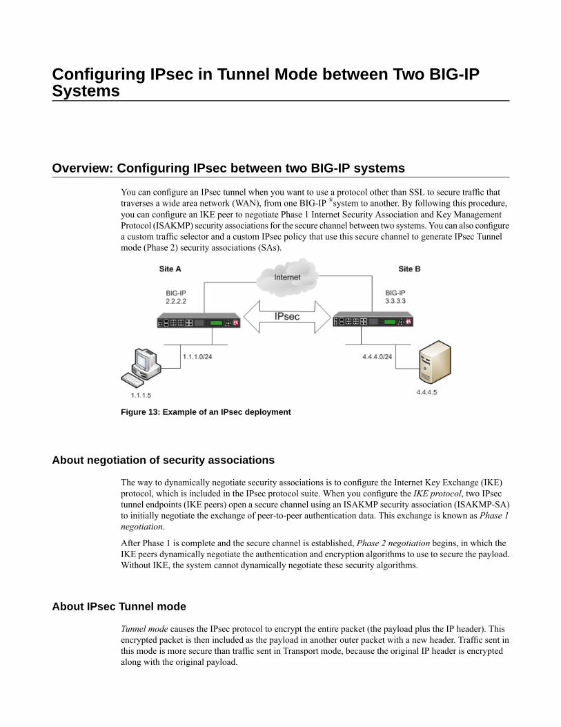
Configuring IPsec in Tunnel Mode between Two BIG-IPSystems
Overview: Configuring IPsec between two BIG-IP systems
You can configure an IPsec tunnel when you want to use a protocol other than SSL to secure traffic thattraverses a wide area network (WAN), from one BIG-IP ®system to another. By following this procedure,you can configure an IKE peer to negotiate Phase 1 Internet Security Association and Key ManagementProtocol (ISAKMP) security associations for the secure channel between two systems. You can also configurea custom traffic selector and a custom IPsec policy that use this secure channel to generate IPsec Tunnelmode (Phase 2) security associations (SAs).
Figure 13: Example of an IPsec deployment
About negotiation of security associations
The way to dynamically negotiate security associations is to configure the Internet Key Exchange (IKE)protocol, which is included in the IPsec protocol suite. When you configure the IKE protocol, two IPsectunnel endpoints (IKE peers) open a secure channel using an ISAKMP security association (ISAKMP-SA)to initially negotiate the exchange of peer-to-peer authentication data. This exchange is known as Phase 1negotiation.
After Phase 1 is complete and the secure channel is established, Phase 2 negotiation begins, in which theIKE peers dynamically negotiate the authentication and encryption algorithms to use to secure the payload.Without IKE, the system cannot dynamically negotiate these security algorithms.
About IPsec Tunnel mode
Tunnel mode causes the IPsec protocol to encrypt the entire packet (the payload plus the IP header). Thisencrypted packet is then included as the payload in another outer packet with a new header. Traffic sent inthis mode is more secure than traffic sent in Transport mode, because the original IP header is encryptedalong with the original payload.
About BIG-IP components of the IPsec protocol suite
The IPsec protocol suite on the BIG-IP® system consists of these configuration components:
IKE peersAn IKE peer is a configuration object of the IPsec protocol suite that represents a BIG-IP system oneach side of the IPsec tunnel. IKE peers allow two systems to authenticate each other (known as IKEPhase 1). The BIG-IP system supports two versions of the IKE protocol: Version 1 (IKEv1) and Version2 (IKEv2). The BIG-IP system includes the default IKE peer, named anonymous, which is configuredto use Version 1.
Note: The BIG-IP system currently supports IKEv2 only in Tunnel mode, and does not support IPCompor NAT-T with IKEv2.
IPsec policiesAn IPsec policy is a set of information that defines the specific IPsec protocol to use (ESP or AH), andthe mode (Transport, Tunnel, or iSession). For Tunnel mode, the policy also specifies the endpoints forthe tunnel, and for IKE Phase 2 negotiation, the policy specifies the security parameters to be used inthat negotiation. The way that you configure the IPsec policy determines the way that the BIG-IP systemmanipulates the IP headers in the packets. The BIG-IP system includes two default IPsec policies, nameddefault-ipsec-policy and default-ipsec-policy-isession. A common configurationincludes a bidirectional policy on each BIG-IP system.
Traffic selectorsA traffic selector is a packet filter that defines what traffic should be handled by a IPsec policy. Youdefine the traffic by source and destination IP addresses and port numbers. A common configurationincludes a bidirectional traffic selector on each BIG-IP system.
About IP Payload Compression Protocol (IPComp)
IP Payload Compression Protocol (IPComp) is a protocol that reduces the size of IP payloads by compressingIP datagrams before fragmenting or encrypting the traffic. IPComp is typically used to improve encryptionand decryption performance, thus increasing bandwidth utilization. Using an IPsec ESP tunnel can resultin packet fragmentation, because the protocol adds a significant number of bytes to a packet. The additionalbytes can push the packet over the maximum size allowed on the outbound link. Using compression is oneway to mitigate fragmentation. IPComp is an option when you create a custom IPsec policy.
Task summary
You can configure the IPsec and IKE protocols to secure traffic that traverses a wide area network (WAN),such as from one data center to another.
Before you begin configuring IPsec and IKE, verify that these modules, system objects, and connectivityexist on the BIG-IP® systems in both the local and remote locations:
BIG-IP Local Traffic Manager™
This module directs traffic securely and efficiently to the appropriate destination on a network.
48
Configuring IPsec in Tunnel Mode between Two BIG-IP Systems
Self IP addressEach BIG-IP systemmust have at least one self IP address, to be used in specifying the ends of the IPsectunnel.
The default VLANsThese VLANs are named external and internal.
BIG-IP connectivityVerify the connectivity between the client or server and its BIG-IP device, and between each BIG-IPdevice and its gateway. For example, you can use ping to test this connectivity.
Task list
Creating a forwarding virtual server for IPsec
For IPsec, you create a forwarding virtual server to intercept IP traffic and direct it over the tunnel.
1. On the Main tab, click Local Traffic > Virtual Servers.The Virtual Server List screen opens.
2. Click the Create button.The New Virtual Server screen opens.
3. In the Name field, type a unique name for the virtual server.4. From the Type list, select Forwarding (IP).5. In theDestination Address field, type a wildcard network address in CIDR format, such as 0.0.0.0/0
for IPv4 or ::/0 for IPv6, to accept any traffic.6. From the Service Port list, select *All Ports.7. From the Protocol list, select *All Protocols.8. From the VLAN and Tunnel Traffic list, retain the default selection, All VLANs and Tunnels.9. Click Finished.
Creating a custom IPsec policy
You create a custom IPsec policy when you want to use a policy other than the default IPsec policy(default-ipsec-policy or default-ipsec-policy-isession). A typical reason for creating acustom IPsec policy is to configure IPsec to operate in Tunnel rather than Transport mode. Another reasonis to add payload compression before encryption. If you are using IKEv2, you must create a custom IPsecpolicy to specify in the traffic selector you create.
Important: You must perform this task on both BIG-IP® systems.
1. On the Main tab, click Network > IPsec > IPsec Policies.2. Click the Create button.
The New Policy screen opens.3. In the Name field, type a unique name for the policy.4. In the Description field, type a brief description of the policy.5. For the IPsec Protocol setting, retain the default selection, ESP.6. From theMode list, select Tunnel.
The screen refreshes to show additional related settings.
49
BIG-IP® TMOS®: Tunneling and IPsec
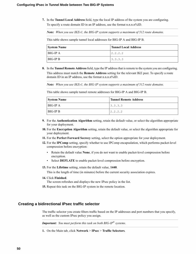
7. In the Tunnel Local Address field, type the local IP address of the system you are configuring.To specify a route domain ID in an IP address, use the format n.n.n.n%ID.
Note: When you use IKEv1, the BIG-IP system supports a maximum of 512 route domains.
This table shows sample tunnel local addresses for BIG-IP A and BIG-IP B.
Tunnel Local AddressSystem Name
2.2.2.2BIG-IP A
3.3.3.3BIG-IP B
8. In theTunnel Remote Address field, type the IP address that is remote to the system you are configuring.This address must match the Remote Address setting for the relevant IKE peer. To specify a routedomain ID in an IP address, use the format n.n.n.n%ID.
Note: When you use IKEv1, the BIG-IP system supports a maximum of 512 route domains.
This table shows sample tunnel remote addresses for BIG-IP A and BIG-IP B.
Tunnel Remote AddressSystem Name
3.3.3.3BIG-IP A
2.2.2.2BIG-IP B
9. For the Authentication Algorithm setting, retain the default value, or select the algorithm appropriatefor your deployment.
10. For the Encryption Algorithm setting, retain the default value, or select the algorithm appropriate foryour deployment.
11. For the Perfect Forward Secrecy setting, select the option appropriate for your deployment.12. For the IPComp setting, specify whether to use IPComp encapsulation, which performs packet-level
compression before encryption:
• Retain the default value None, if you do not want to enable packet-level compression beforeencryption.
• Select DEFLATE to enable packet-level compression before encryption.
13. For the Lifetime setting, retain the default value, 1440.This is the length of time (in minutes) before the current security association expires.
14. Click Finished.The screen refreshes and displays the new IPsec policy in the list.
15. Repeat this task on the BIG-IP system in the remote location.
Creating a bidirectional IPsec traffic selector
The traffic selector you create filters traffic based on the IP addresses and port numbers that you specify,as well as the custom IPsec policy you assign.
Important: You must perform this task on both BIG-IP® systems.
1. On the Main tab, click Network > IPsec > Traffic Selectors.
50
Configuring IPsec in Tunnel Mode between Two BIG-IP Systems
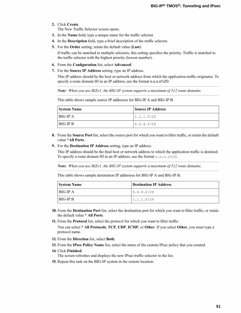
2. Click Create.The New Traffic Selector screen opens.
3. In the Name field, type a unique name for the traffic selector.4. In the Description field, type a brief description of the traffic selector.5. For the Order setting, retain the default value (Last).
If traffic can be matched to multiple selectors, this setting specifies the priority. Traffic is matched tothe traffic selector with the highest priority (lowest number).
6. From the Configuration list, select Advanced.7. For the Source IP Address setting, type an IP address.
This IP address should be the host or network address from which the application traffic originates. Tospecify a route domain ID in an IP address, use the format n.n.n.n%ID.
Note: When you use IKEv1, the BIG-IP system supports a maximum of 512 route domains.
This table shows sample source IP addresses for BIG-IP A and BIG-IP B.
Source IP AddressSystem Name
1.1.1.0/24BIG-IP A
4.4.4.0/24BIG-IP B
8. From the Source Port list, select the source port for which you want to filter traffic, or retain the defaultvalue *All Ports.
9. For the Destination IP Address setting, type an IP address.This IP address should be the final host or network address to which the application traffic is destined.To specify a route domain ID in an IP address, use the format n.n.n.n%ID.
Note: When you use IKEv1, the BIG-IP system supports a maximum of 512 route domains.
This table shows sample destination IP addresses for BIG-IP A and BIG-IP B.
Destination IP AddressSystem Name
4.4.4.0/24BIG-IP A
1.1.1.0/24BIG-IP B
10. From the Destination Port list, select the destination port for which you want to filter traffic, or retainthe default value * All Ports.
11. From the Protocol list, select the protocol for which you want to filter traffic.You can select * All Protocols, TCP, UDP, ICMP, or Other. If you select Other, you must type aprotocol name.
12. From the Direction list, select Both.13. From the IPsec Policy Name list, select the name of the custom IPsec policy that you created.14. Click Finished.
The screen refreshes and displays the new IPsec traffic selector in the list.15. Repeat this task on the BIG-IP system in the remote location.
51
BIG-IP® TMOS®: Tunneling and IPsec
Creating an IKE peer
The IKE peer object identifies to the system you are configuring the other BIG-IP® system with which itcommunicates during Phase 1 negotiations. The IKE peer object also specifies the specific algorithms andcredentials to be used for Phase 1 negotiation.
Important: You must perform these steps on both BIG-IP systems.
1. On the Main tab, click Network > IPsec > IKE Peers.2. Click the Create button.
The New IKE Peer screen opens.3. In the Name field, type a unique name for the IKE peer.4. In the Description field, type a brief description of the IKE peer.5. In the Remote Address field, type the IP address of the BIG-IP system that is remote to the system you
are configuring.To specify a route domain ID in an IP address, use the format n.n.n.n%ID.
Note: When you use IKEv1, the BIG-IP system supports a maximum of 512 route domains.
6. For the State setting, retain the default value, Enabled.7. For the Version setting, select either version or both versions.
To successfully create an IPsec tunnel, the remote IKE peer must use the same version.
Note: Currently, IKEv2 is supported only for Tunnel mode, which you specify when you create the IPsecpolicy. Some parameters are supported only by IKEv1, as indicated on the IKE Peer screens.
If you select both versions:
• And the system you are configuring is the IPsec initiator, the system tries using IKEv2 for negotiation.If the remote peer does not support IKEv2, the IPsec tunnel fails. To use IKEv1 in this case, clearthe Version 2 check box, and try again.
• And the system you are configuring is the IPsec responder, the IPsec initiator system determineswhich IKE version to use.
8. For the IKE Phase 1 Algorithms area, retain the default values, or select the options that are appropriatefor your deployment.
9. In the IKE Phase 1 Credentials area, for theAuthenticationMethod setting, select the option appropriatefor your deployment.
• If you select RSA Signature (default), the Certificate, Key, and Verify Peer Certificate settingsare available. If you have your own certificate file, key file, and certificate authority (CA), F5recommends, for security purposes, that you specify these files in the appropriate fields. To revealall these fields, select theVerify Peer Certificate check box. If you retain the default settings, leavethe check box cleared.
Important: If you select the check box, you must provide a certificate file, key, and certificateauthority.
Note: This option is available only for IKEv1.
• If you select Preshared Key, type the key in the Preshared Key field that becomes available.
52
Configuring IPsec in Tunnel Mode between Two BIG-IP Systems
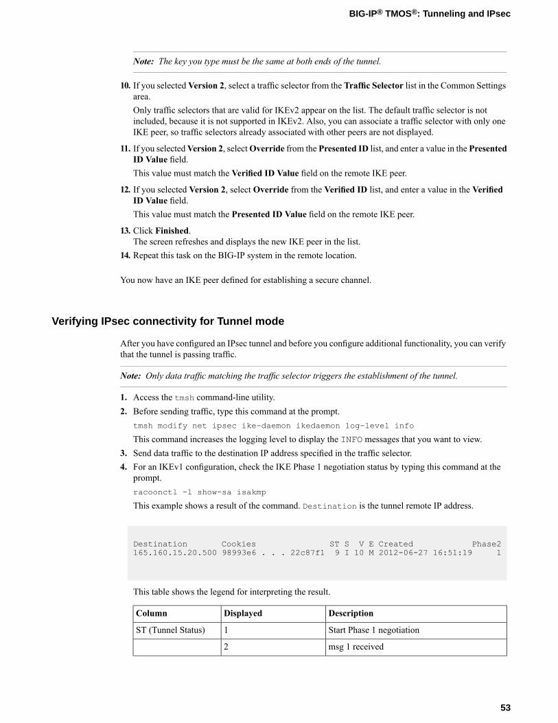
Note: The key you type must be the same at both ends of the tunnel.
10. If you selectedVersion 2, select a traffic selector from the Traffic Selector list in the Common Settingsarea.Only traffic selectors that are valid for IKEv2 appear on the list. The default traffic selector is notincluded, because it is not supported in IKEv2. Also, you can associate a traffic selector with only oneIKE peer, so traffic selectors already associated with other peers are not displayed.
11. If you selectedVersion 2, selectOverride from the Presented ID list, and enter a value in the PresentedID Value field.This value must match the Verified ID Value field on the remote IKE peer.
12. If you selected Version 2, select Override from the Verified ID list, and enter a value in the VerifiedID Value field.This value must match the Presented ID Value field on the remote IKE peer.
13. Click Finished.The screen refreshes and displays the new IKE peer in the list.
14. Repeat this task on the BIG-IP system in the remote location.
You now have an IKE peer defined for establishing a secure channel.
Verifying IPsec connectivity for Tunnel mode
After you have configured an IPsec tunnel and before you configure additional functionality, you can verifythat the tunnel is passing traffic.
Note: Only data traffic matching the traffic selector triggers the establishment of the tunnel.
1. Access the tmsh command-line utility.2. Before sending traffic, type this command at the prompt.
tmsh modify net ipsec ike-daemon ikedaemon log-level info
This command increases the logging level to display the INFO messages that you want to view.3. Send data traffic to the destination IP address specified in the traffic selector.4. For an IKEv1 configuration, check the IKE Phase 1 negotiation status by typing this command at the
prompt.racoonctl -l show-sa isakmp
This example shows a result of the command. Destination is the tunnel remote IP address.
Destination Cookies ST S V E Created Phase2165.160.15.20.500 98993e6 . . . 22c87f1 9 I 10 M 2012-06-27 16:51:19 1
This table shows the legend for interpreting the result.
DescriptionDisplayedColumn
Start Phase 1 negotiation1ST (Tunnel Status)
msg 1 received2
53
BIG-IP® TMOS®: Tunneling and IPsec
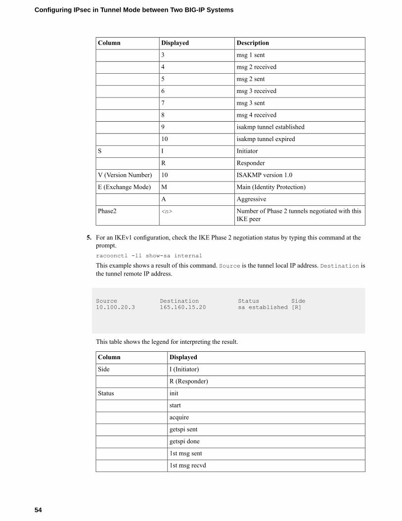
DescriptionDisplayedColumn
msg 1 sent3
msg 2 received4
msg 2 sent5
msg 3 received6
msg 3 sent7
msg 4 received8
isakmp tunnel established9
isakmp tunnel expired10
InitiatorIS
ResponderR
ISAKMP version 1.010V (Version Number)
Main (Identity Protection)ME (Exchange Mode)
AggressiveA
Number of Phase 2 tunnels negotiated with thisIKE peer
<n>Phase2
5. For an IKEv1 configuration, check the IKE Phase 2 negotiation status by typing this command at theprompt.racoonctl -ll show-sa internal
This example shows a result of this command. Source is the tunnel local IP address. Destination isthe tunnel remote IP address.
Source Destination Status Side10.100.20.3 165.160.15.20 sa established [R]
This table shows the legend for interpreting the result.
DisplayedColumn
I (Initiator)Side
R (Responder)
initStatus
start
acquire
getspi sent
getspi done
1st msg sent
1st msg recvd
54
Configuring IPsec in Tunnel Mode between Two BIG-IP Systems
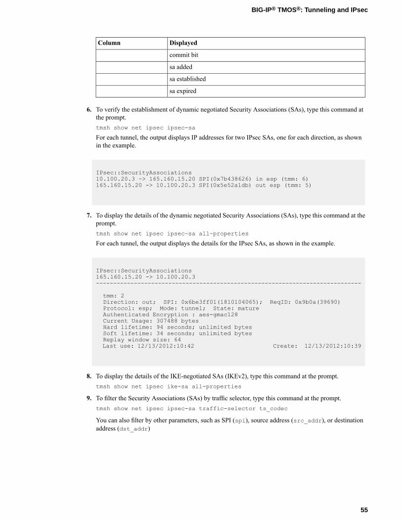
DisplayedColumn
commit bit
sa added
sa established
sa expired
6. To verify the establishment of dynamic negotiated Security Associations (SAs), type this command atthe prompt.tmsh show net ipsec ipsec-sa
For each tunnel, the output displays IP addresses for two IPsec SAs, one for each direction, as shownin the example.
IPsec::SecurityAssociations10.100.20.3 -> 165.160.15.20 SPI(0x7b438626) in esp (tmm: 6)165.160.15.20 -> 10.100.20.3 SPI(0x5e52a1db) out esp (tmm: 5)
7. To display the details of the dynamic negotiated Security Associations (SAs), type this command at theprompt.tmsh show net ipsec ipsec-sa all-properties
For each tunnel, the output displays the details for the IPsec SAs, as shown in the example.
IPsec::SecurityAssociations165.160.15.20 -> 10.100.20.3-----------------------------------------------------------------------------
tmm: 2Direction: out; SPI: 0x6be3ff01(1810104065); ReqID: 0x9b0a(39690)Protocol: esp; Mode: tunnel; State: matureAuthenticated Encryption : aes-gmac128Current Usage: 307488 bytesHard lifetime: 94 seconds; unlimited bytesSoft lifetime: 34 seconds; unlimited bytesReplay window size: 64Last use: 12/13/2012:10:42 Create: 12/13/2012:10:39
8. To display the details of the IKE-negotiated SAs (IKEv2), type this command at the prompt.tmsh show net ipsec ike-sa all-properties
9. To filter the Security Associations (SAs) by traffic selector, type this command at the prompt.tmsh show net ipsec ipsec-sa traffic-selector ts_codec
You can also filter by other parameters, such as SPI (spi), source address (src_addr), or destinationaddress (dst_addr)
55
BIG-IP® TMOS®: Tunneling and IPsec
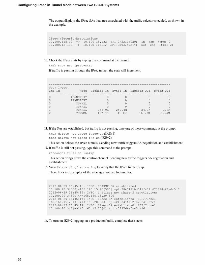
The output displays the IPsec SAs that area associated with the traffic selector specified, as shown inthe example.
IPsec::SecurityAssociations10.100.115.12 -> 10.100.15.132 SPI(0x2211c0a9) in esp (tmm: 0)10.100.15.132 -> 10.100.115.12 SPI(0x932e0c44) out esp (tmm: 2)
10. Check the IPsec stats by typing this command at the prompt.tmsh show net ipsec-stat
If traffic is passing through the IPsec tunnel, the stats will increment.
-------------------------------------------------------------------Net::IpsecCmd Id Mode Packets In Bytes In Packets Out Bytes Out-------------------------------------------------------------------0 TRANSPORT 0 0 0 00 TRANSPORT 0 0 0 00 TUNNEL 0 0 0 00 TUNNEL 0 0 0 01 TUNNEL 353.9K 252.4M 24.9K 1.8M2 TUNNEL 117.9K 41.0M 163.3K 12.4M
11. If the SAs are established, but traffic is not passing, type one of these commands at the prompt.tmsh delete net ipsec ipsec-sa (IKEv1)tmsh delete net ipsec ike-sa (IKEv2)This action deletes the IPsec tunnels. Sending new traffic triggers SA negotiation and establishment.
12. If traffic is still not passing, type this command at the prompt.racoonctl flush-sa isakmp
This action brings down the control channel. Sending new traffic triggers SA negotiation andestablishment.
13. View the /var/log/racoon.log to verify that the IPsec tunnel is up.These lines are examples of the messages you are looking for.
2012-06-29 16:45:13: INFO: ISAKMP-SA established10.100.20.3[500]-165.160.15.20[500] spi:3840191bd045fa51:673828cf6adc5c612012-06-29 16:45:14: INFO: initiate new phase 2 negotiation:10.100.20.3[500]<=>165.160.15.20[500]2012-06-29 16:45:14: INFO: IPsec-SA established: ESP/Tunnel165.160.15.20[0]->10.100.20.3[0] spi=2403416622(0x8f413a2e)2012-06-29 16:45:14: INFO: IPsec-SA established: ESP/Tunnel10.100.20.3[0]->165.160.15.20[0] spi=4573766(0x45ca46
14. To turn on IKEv2 logging on a production build, complete these steps.
56
Configuring IPsec in Tunnel Mode between Two BIG-IP Systems
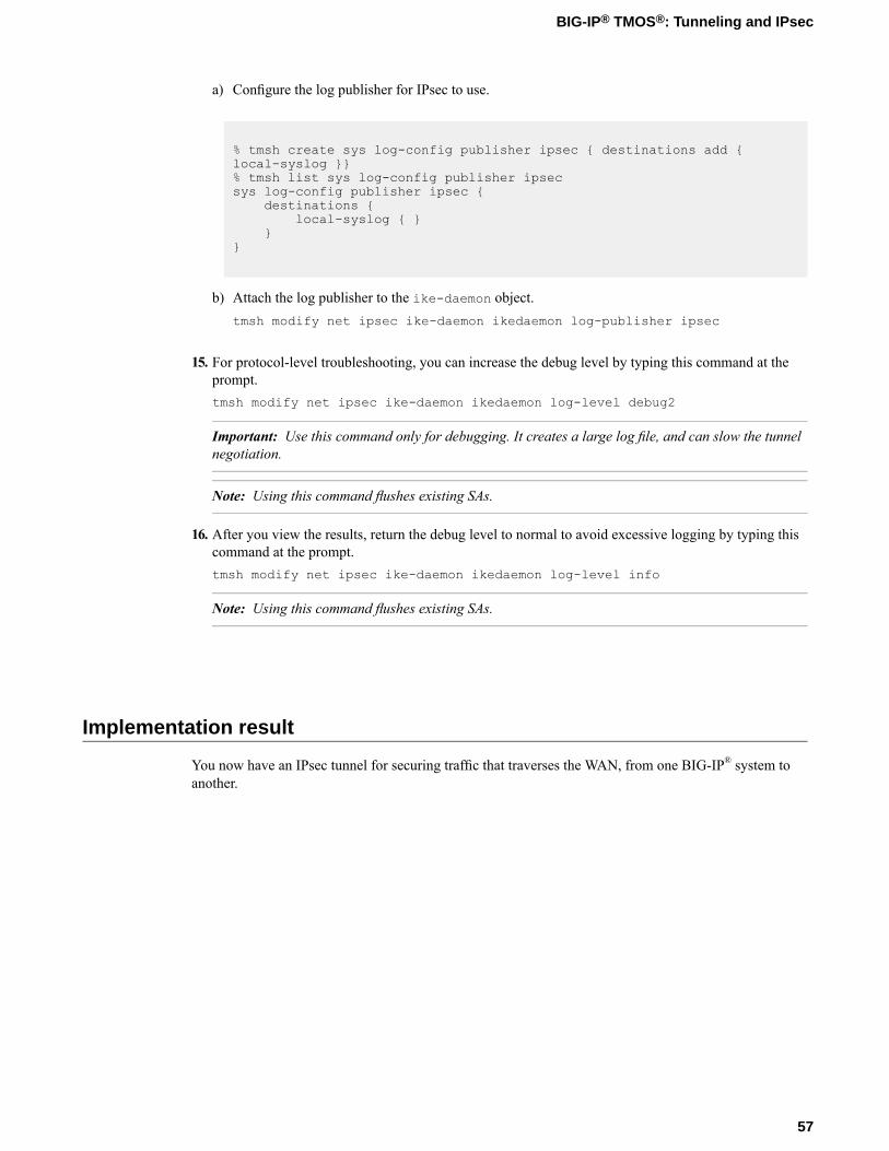
a) Configure the log publisher for IPsec to use.
% tmsh create sys log-config publisher ipsec { destinations add {local-syslog }}% tmsh list sys log-config publisher ipsecsys log-config publisher ipsec {
destinations {local-syslog { }
}}
b) Attach the log publisher to the ike-daemon object.tmsh modify net ipsec ike-daemon ikedaemon log-publisher ipsec
15. For protocol-level troubleshooting, you can increase the debug level by typing this command at theprompt.tmsh modify net ipsec ike-daemon ikedaemon log-level debug2
Important: Use this command only for debugging. It creates a large log file, and can slow the tunnelnegotiation.
Note: Using this command flushes existing SAs.
16. After you view the results, return the debug level to normal to avoid excessive logging by typing thiscommand at the prompt.tmsh modify net ipsec ike-daemon ikedaemon log-level info
Note: Using this command flushes existing SAs.
Implementation result
You now have an IPsec tunnel for securing traffic that traverses the WAN, from one BIG-IP® system toanother.
57
BIG-IP® TMOS®: Tunneling and IPsec

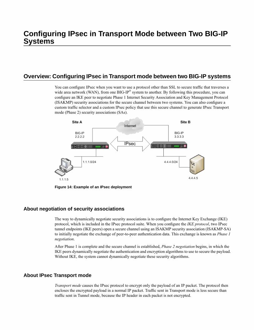
Configuring IPsec in Transport Mode between Two BIG-IPSystems
Overview: Configuring IPsec in Transport mode between two BIG-IP systems
You can configure IPsec when you want to use a protocol other than SSL to secure traffic that traverses awide area network (WAN), from one BIG-IP® system to another. By following this procedure, you canconfigure an IKE peer to negotiate Phase 1 Internet Security Association and Key Management Protocol(ISAKMP) security associations for the secure channel between two systems. You can also configure acustom traffic selector and a custom IPsec policy that use this secure channel to generate IPsec Transportmode (Phase 2) security associations (SAs).
Figure 14: Example of an IPsec deployment
About negotiation of security associations
The way to dynamically negotiate security associations is to configure the Internet Key Exchange (IKE)protocol, which is included in the IPsec protocol suite. When you configure the IKE protocol, two IPsectunnel endpoints (IKE peers) open a secure channel using an ISAKMP security association (ISAKMP-SA)to initially negotiate the exchange of peer-to-peer authentication data. This exchange is known as Phase 1negotiation.
After Phase 1 is complete and the secure channel is established, Phase 2 negotiation begins, in which theIKE peers dynamically negotiate the authentication and encryption algorithms to use to secure the payload.Without IKE, the system cannot dynamically negotiate these security algorithms.
About IPsec Transport mode
Transport mode causes the IPsec protocol to encrypt only the payload of an IP packet. The protocol thenencloses the encrypted payload in a normal IP packet. Traffic sent in Transport mode is less secure thantraffic sent in Tunnel mode, because the IP header in each packet is not encrypted.
About BIG-IP components of the IPsec protocol suite
The IPsec protocol suite on the BIG-IP® system consists of these configuration components:
IKE peersAn IKE peer is a configuration object of the IPsec protocol suite that represents a BIG-IP system oneach side of the IPsec tunnel. IKE peers allow two systems to authenticate each other (known as IKEPhase 1). The BIG-IP system supports two versions of the IKE protocol: Version 1 (IKEv1) and Version2 (IKEv2). The BIG-IP system includes the default IKE peer, named anonymous, which is configuredto use Version 1.
Note: The BIG-IP system currently supports IKEv2 only in Tunnel mode, and does not support IPCompor NAT-T with IKEv2.
IPsec policiesAn IPsec policy is a set of information that defines the specific IPsec protocol to use (ESP or AH), andthe mode (Transport, Tunnel, or iSession). For Tunnel mode, the policy also specifies the endpoints forthe tunnel, and for IKE Phase 2 negotiation, the policy specifies the security parameters to be used inthat negotiation. The way that you configure the IPsec policy determines the way that the BIG-IP systemmanipulates the IP headers in the packets. The BIG-IP system includes two default IPsec policies, nameddefault-ipsec-policy and default-ipsec-policy-isession. A common configurationincludes a bidirectional policy on each BIG-IP system.
Traffic selectorsA traffic selector is a packet filter that defines what traffic should be handled by a IPsec policy. Youdefine the traffic by source and destination IP addresses and port numbers. A common configurationincludes a bidirectional traffic selector on each BIG-IP system.
About IP Payload Compression Protocol (IPComp)
IP Payload Compression Protocol (IPComp) is a protocol that reduces the size of IP payloads by compressingIP datagrams before fragmenting or encrypting the traffic. IPComp is typically used to improve encryptionand decryption performance, thus increasing bandwidth utilization. Using an IPsec ESP tunnel can resultin packet fragmentation, because the protocol adds a significant number of bytes to a packet. The additionalbytes can push the packet over the maximum size allowed on the outbound link. Using compression is oneway to mitigate fragmentation. IPComp is an option when you create a custom IPsec policy.
Task summary
With this task, you can configure the IPsec and IKE protocols to secure traffic that traverses a wide areanetwork (WAN), such as from one data center to another.
Before you begin configuring IPsec and IKE, verify that these modules, system objects, and connectivityexist on the BIG-IP® systems in both the local and remote locations:
BIG-IP Local Traffic Manager™
This module directs traffic securely and efficiently to the appropriate destination on a network.
60
Configuring IPsec in Transport Mode between Two BIG-IP Systems
Self IP addressEach BIG-IP systemmust have at least one self IP address, to be used in specifying the ends of the IPsectunnel.
The default VLANsThese VLANs are named external and internal.
BIG-IP connectivityVerify the connectivity between the client or server and its BIG-IP device, and between each BIG-IPdevice and its gateway. For example, you can use ping to test this connectivity.
Task list
Creating a forwarding virtual server for IPsec
For IPsec, you create a forwarding virtual server to intercept IP traffic and direct it over the tunnel.
1. On the Main tab, click Local Traffic > Virtual Servers.The Virtual Server List screen opens.
2. Click the Create button.The New Virtual Server screen opens.
3. In the Name field, type a unique name for the virtual server.4. From the Type list, select Forwarding (IP).5. In theDestination Address field, type a wildcard network address in CIDR format, such as 0.0.0.0/0
for IPv4 or ::/0 for IPv6, to accept any traffic.6. From the Service Port list, select *All Ports.7. From the Protocol list, select *All Protocols.8. From the VLAN and Tunnel Traffic list, retain the default selection, All VLANs and Tunnels.9. Click Finished.
Creating an IKE peer
The IKE peer object identifies to the system you are configuring the other BIG-IP® system with which itcommunicates during Phase 1 negotiations. The IKE peer object also specifies the specific algorithms andcredentials to be used for Phase 1 negotiation.
Important: You must perform these steps on both BIG-IP systems.
1. On the Main tab, click Network > IPsec > IKE Peers.2. Click the Create button.
The New IKE Peer screen opens.3. In the Name field, type a unique name for the IKE peer.4. In the Description field, type a brief description of the IKE peer.5. In the Remote Address field, type the IP address of the BIG-IP system that is remote to the system you
are configuring.To specify a route domain ID in an IP address, use the format n.n.n.n%ID.
Note: When you use IKEv1, the BIG-IP system supports a maximum of 512 route domains.
61
BIG-IP® TMOS®: Tunneling and IPsec
6. For the State setting, retain the default value, Enabled.7. For the Version setting, select either version or both versions.
To successfully create an IPsec tunnel, the remote IKE peer must use the same version.
Note: Currently, IKEv2 is supported only for Tunnel mode, which you specify when you create the IPsecpolicy. Some parameters are supported only by IKEv1, as indicated on the IKE Peer screens.
If you select both versions:
• And the system you are configuring is the IPsec initiator, the system tries using IKEv2 for negotiation.If the remote peer does not support IKEv2, the IPsec tunnel fails. To use IKEv1 in this case, clearthe Version 2 check box, and try again.
• And the system you are configuring is the IPsec responder, the IPsec initiator system determineswhich IKE version to use.
8. For the IKE Phase 1 Algorithms area, retain the default values, or select the options that are appropriatefor your deployment.
9. In the IKE Phase 1 Credentials area, for theAuthenticationMethod setting, select the option appropriatefor your deployment.
• If you select RSA Signature (default), the Certificate, Key, and Verify Peer Certificate settingsare available. If you have your own certificate file, key file, and certificate authority (CA), F5recommends, for security purposes, that you specify these files in the appropriate fields. To revealall these fields, select theVerify Peer Certificate check box. If you retain the default settings, leavethe check box cleared.
Important: If you select the check box, you must provide a certificate file, key, and certificateauthority.
Note: This option is available only for IKEv1.
• If you select Preshared Key, type the key in the Preshared Key field that becomes available.
Note: The key you type must be the same at both ends of the tunnel.
10. If you selectedVersion 2, select a traffic selector from the Traffic Selector list in the Common Settingsarea.Only traffic selectors that are valid for IKEv2 appear on the list. The default traffic selector is notincluded, because it is not supported in IKEv2. Also, you can associate a traffic selector with only oneIKE peer, so traffic selectors already associated with other peers are not displayed.
11. If you selectedVersion 2, selectOverride from the Presented ID list, and enter a value in the PresentedID Value field.This value must match the Verified ID Value field on the remote IKE peer.
12. If you selected Version 2, select Override from the Verified ID list, and enter a value in the VerifiedID Value field.This value must match the Presented ID Value field on the remote IKE peer.
13. Click Finished.The screen refreshes and displays the new IKE peer in the list.
14. Repeat this task on the BIG-IP system in the remote location.
You now have an IKE peer defined for establishing a secure channel.
62
Configuring IPsec in Transport Mode between Two BIG-IP Systems
Creating a bidirectional IPsec policy
You create a custom IPsec policy when you want to use a policy other than the default IPsec policy(default-ipsec-policy or default-ipsec-policy-isession). A typical reason for creating acustom IPsec policy is to configure IPsec to operate in Tunnel rather than Transport mode. Another reasonis to add payload compression before encryption. If you are using IKEv2, you must create a custom IPsecpolicy to specify in the traffic selector you create.
Important: You must perform this task on both BIG-IP® systems.
1. On the Main tab, click Network > IPsec > IPsec Policies.2. Click the Create button.
The New Policy screen opens.3. In the Name field, type a unique name for the policy.4. In the Description field, type a brief description of the policy.5. For the IPsec Protocol setting, retain the default selection, ESP.6. From theMode list, select Transport.7. For the Authentication Algorithm setting, retain the default value, or select the algorithm appropriate
for your deployment.8. For the Encryption Algorithm setting, retain the default value, or select the algorithm appropriate for
your deployment.9. For the Perfect Forward Secrecy setting, select the option appropriate for your deployment.10. For the IPComp setting, specify whether to use IPComp encapsulation, which performs packet-level
compression before encryption:
• Retain the default value None, if you do not want to enable packet-level compression beforeencryption.
• Select DEFLATE to enable packet-level compression before encryption.
11. For the Lifetime setting, retain the default value, 1440.This is the length of time (in minutes) before the current security association expires.
12. Click Finished.The screen refreshes and displays the new IPsec policy in the list.
13. Repeat this task on the BIG-IP system in the remote location.
Creating a bidirectional IPsec traffic selector
The traffic selector you create filters traffic based on the IP addresses and port numbers that you specify,as well as the custom IPsec policy you assign.
Important: You must perform this task on both BIG-IP® systems.
1. On the Main tab, click Network > IPsec > Traffic Selectors.2. Click Create.
The New Traffic Selector screen opens.3. In the Name field, type a unique name for the traffic selector.4. In the Description field, type a brief description of the traffic selector.5. For the Order setting, retain the default value (Last).
63
BIG-IP® TMOS®: Tunneling and IPsec
If traffic can be matched to multiple selectors, this setting specifies the priority. Traffic is matched tothe traffic selector with the highest priority (lowest number).
6. From the Configuration list, select Advanced.7. For the Source IP Address setting, type an IP address.
This IP address should be the host or network address from which the application traffic originates. Tospecify a route domain ID in an IP address, use the format n.n.n.n%ID.
Note: When you use IKEv1, the BIG-IP system supports a maximum of 512 route domains.
This table shows sample source IP addresses for BIG-IP A and BIG-IP B.
Source IP AddressSystem Name
1.1.1.0/24BIG-IP A
4.4.4.0/24BIG-IP B
8. From the Source Port list, select the source port for which you want to filter traffic, or retain the defaultvalue *All Ports.
9. For the Destination IP Address setting, type an IP address.This IP address should be the final host or network address to which the application traffic is destined.To specify a route domain ID in an IP address, use the format n.n.n.n%ID.
Note: When you use IKEv1, the BIG-IP system supports a maximum of 512 route domains.
This table shows sample destination IP addresses for BIG-IP A and BIG-IP B.
Destination IP AddressSystem Name
4.4.4.0/24BIG-IP A
1.1.1.0/24BIG-IP B
10. From the Destination Port list, select the destination port for which you want to filter traffic, or retainthe default value * All Ports.
11. From the Protocol list, select the protocol for which you want to filter traffic.You can select * All Protocols, TCP, UDP, ICMP, or Other. If you select Other, you must type aprotocol name.
12. From the Direction list, select Both.13. From the IPsec Policy Name list, select the name of the custom IPsec policy that you created.14. Click Finished.
The screen refreshes and displays the new IPsec traffic selector in the list.15. Repeat this task on the BIG-IP system in the remote location.
Verifying IPsec connectivity for Transport mode
After you have configured an IPsec tunnel and before you configure additional functionality, you can verifythat the tunnel is passing traffic.
Note: Only data traffic triggers the establishment of the tunnel.
.
64
Configuring IPsec in Transport Mode between Two BIG-IP Systems
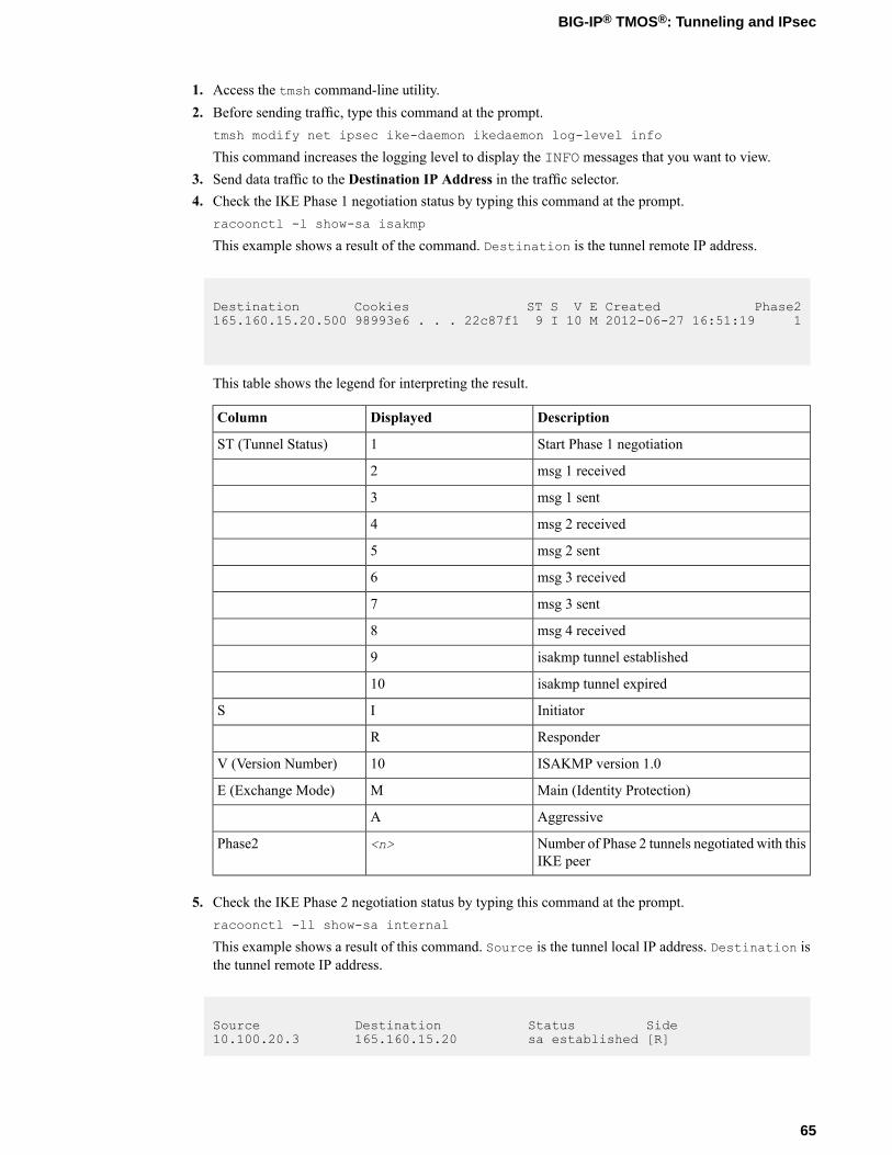
1. Access the tmsh command-line utility.2. Before sending traffic, type this command at the prompt.
tmsh modify net ipsec ike-daemon ikedaemon log-level info
This command increases the logging level to display the INFO messages that you want to view.3. Send data traffic to the Destination IP Address in the traffic selector.4. Check the IKE Phase 1 negotiation status by typing this command at the prompt.
racoonctl -l show-sa isakmp
This example shows a result of the command. Destination is the tunnel remote IP address.
Destination Cookies ST S V E Created Phase2165.160.15.20.500 98993e6 . . . 22c87f1 9 I 10 M 2012-06-27 16:51:19 1
This table shows the legend for interpreting the result.
DescriptionDisplayedColumn
Start Phase 1 negotiation1ST (Tunnel Status)
msg 1 received2
msg 1 sent3
msg 2 received4
msg 2 sent5
msg 3 received6
msg 3 sent7
msg 4 received8
isakmp tunnel established9
isakmp tunnel expired10
InitiatorIS
ResponderR
ISAKMP version 1.010V (Version Number)
Main (Identity Protection)ME (Exchange Mode)
AggressiveA
Number of Phase 2 tunnels negotiated with thisIKE peer
<n>Phase2
5. Check the IKE Phase 2 negotiation status by typing this command at the prompt.racoonctl -ll show-sa internal
This example shows a result of this command. Source is the tunnel local IP address. Destination isthe tunnel remote IP address.
Source Destination Status Side10.100.20.3 165.160.15.20 sa established [R]
65
BIG-IP® TMOS®: Tunneling and IPsec
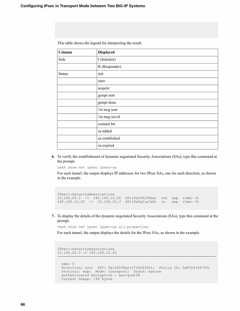
This table shows the legend for interpreting the result.
DisplayedColumn
I (Initiator)Side
R (Responder)
initStatus
start
acquire
getspi sent
getspi done
1st msg sent
1st msg recvd
commit bit
sa added
sa established
sa expired
6. To verify the establishment of dynamic negotiated Security Associations (SAs), type this command atthe prompt.tmsh show net ipsec ipsec-sa
For each tunnel, the output displays IP addresses for two IPsec SAs, one for each direction, as shownin the example.
IPsec::SecurityAssociations10.100.20.3 -> 165.160.15.20 SPI(0x164208ae) out esp (tmm: 0)165.160.15.20 -> 10.100.20.3 SPI(0xfa2ca7a8) in esp (tmm: 0)
7. To display the details of the dynamic negotiated Security Associations (SAs), type this command at theprompt.tmsh show net ipsec ipsec-sa all-properties
For each tunnel, the output displays the details for the IPsec SAs, as shown in the example.
IPsec::SecurityAssociations10.100.20.3 -> 165.160.15.20-----------------------------------------------------------------------------------------------------
tmm: 0Direction: out; SPI: 0x164208ae(373426350); Policy ID: 0x87e9(34793)Protocol: esp; Mode: transport; State: matureAuthenticated Encryption : aes-gcm128Current Usage: 196 bytes
66
Configuring IPsec in Transport Mode between Two BIG-IP Systems
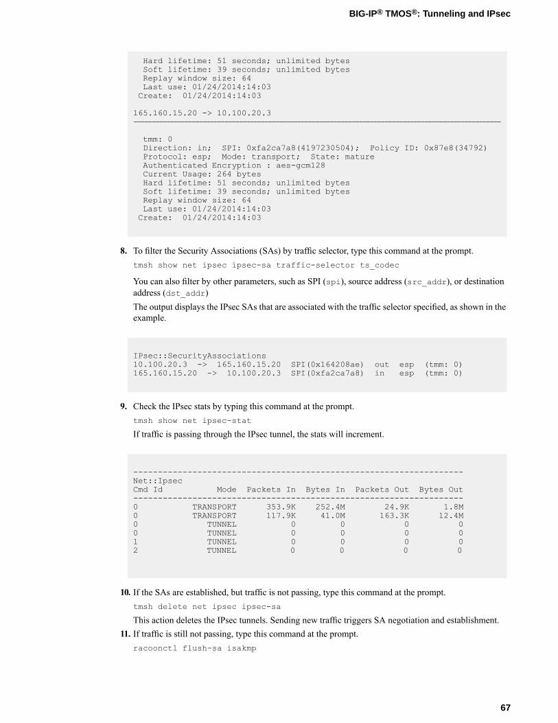
Hard lifetime: 51 seconds; unlimited bytesSoft lifetime: 39 seconds; unlimited bytesReplay window size: 64Last use: 01/24/2014:14:03Create: 01/24/2014:14:03
165.160.15.20 -> 10.100.20.3-----------------------------------------------------------------------------------------------------
tmm: 0Direction: in; SPI: 0xfa2ca7a8(4197230504); Policy ID: 0x87e8(34792)Protocol: esp; Mode: transport; State: matureAuthenticated Encryption : aes-gcm128Current Usage: 264 bytesHard lifetime: 51 seconds; unlimited bytesSoft lifetime: 39 seconds; unlimited bytesReplay window size: 64Last use: 01/24/2014:14:03Create: 01/24/2014:14:03
8. To filter the Security Associations (SAs) by traffic selector, type this command at the prompt.tmsh show net ipsec ipsec-sa traffic-selector ts_codec
You can also filter by other parameters, such as SPI (spi), source address (src_addr), or destinationaddress (dst_addr)The output displays the IPsec SAs that are associated with the traffic selector specified, as shown in theexample.
IPsec::SecurityAssociations10.100.20.3 -> 165.160.15.20 SPI(0x164208ae) out esp (tmm: 0)165.160.15.20 -> 10.100.20.3 SPI(0xfa2ca7a8) in esp (tmm: 0)
9. Check the IPsec stats by typing this command at the prompt.tmsh show net ipsec-stat
If traffic is passing through the IPsec tunnel, the stats will increment.
-------------------------------------------------------------------Net::IpsecCmd Id Mode Packets In Bytes In Packets Out Bytes Out-------------------------------------------------------------------0 TRANSPORT 353.9K 252.4M 24.9K 1.8M0 TRANSPORT 117.9K 41.0M 163.3K 12.4M0 TUNNEL 0 0 0 00 TUNNEL 0 0 0 01 TUNNEL 0 0 0 02 TUNNEL 0 0 0 0
10. If the SAs are established, but traffic is not passing, type this command at the prompt.tmsh delete net ipsec ipsec-sa
This action deletes the IPsec tunnels. Sending new traffic triggers SA negotiation and establishment.11. If traffic is still not passing, type this command at the prompt.
racoonctl flush-sa isakmp
67
BIG-IP® TMOS®: Tunneling and IPsec
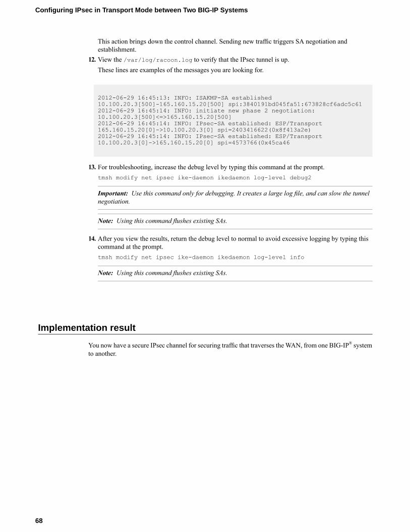
This action brings down the control channel. Sending new traffic triggers SA negotiation andestablishment.
12. View the /var/log/racoon.log to verify that the IPsec tunnel is up.These lines are examples of the messages you are looking for.
2012-06-29 16:45:13: INFO: ISAKMP-SA established10.100.20.3[500]-165.160.15.20[500] spi:3840191bd045fa51:673828cf6adc5c612012-06-29 16:45:14: INFO: initiate new phase 2 negotiation:10.100.20.3[500]<=>165.160.15.20[500]2012-06-29 16:45:14: INFO: IPsec-SA established: ESP/Transport165.160.15.20[0]->10.100.20.3[0] spi=2403416622(0x8f413a2e)2012-06-29 16:45:14: INFO: IPsec-SA established: ESP/Transport10.100.20.3[0]->165.160.15.20[0] spi=4573766(0x45ca46
13. For troubleshooting, increase the debug level by typing this command at the prompt.tmsh modify net ipsec ike-daemon ikedaemon log-level debug2
Important: Use this command only for debugging. It creates a large log file, and can slow the tunnelnegotiation.
Note: Using this command flushes existing SAs.
14. After you view the results, return the debug level to normal to avoid excessive logging by typing thiscommand at the prompt.tmsh modify net ipsec ike-daemon ikedaemon log-level info
Note: Using this command flushes existing SAs.
Implementation result
You now have a secure IPsec channel for securing traffic that traverses theWAN, from one BIG-IP® systemto another.
68
Configuring IPsec in Transport Mode between Two BIG-IP Systems
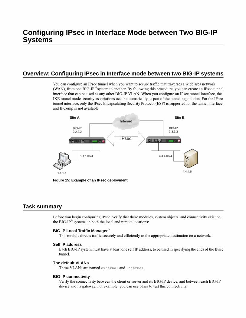
Configuring IPsec in Interface Mode between Two BIG-IPSystems
Overview: Configuring IPsec in Interface mode between two BIG-IP systems
You can configure an IPsec tunnel when you want to secure traffic that traverses a wide area network(WAN), from one BIG-IP ®system to another. By following this procedure, you can create an IPsec tunnelinterface that can be used as any other BIG-IP VLAN. When you configure an IPsec tunnel interface, theIKE tunnel mode security associations occur automatically as part of the tunnel negotiation. For the IPsectunnel interface, only the IPsec Encapsulating Security Protocol (ESP) is supported for the tunnel interface,and IPComp is not available.
Figure 15: Example of an IPsec deployment
Task summary
Before you begin configuring IPsec, verify that these modules, system objects, and connectivity exist onthe BIG-IP® systems in both the local and remote locations:
BIG-IP Local Traffic Manager™
This module directs traffic securely and efficiently to the appropriate destination on a network.
Self IP addressEach BIG-IP systemmust have at least one self IP address, to be used in specifying the ends of the IPsectunnel.
The default VLANsThese VLANs are named external and internal.
BIG-IP connectivityVerify the connectivity between the client or server and its BIG-IP device, and between each BIG-IPdevice and its gateway. For example, you can use ping to test this connectivity.
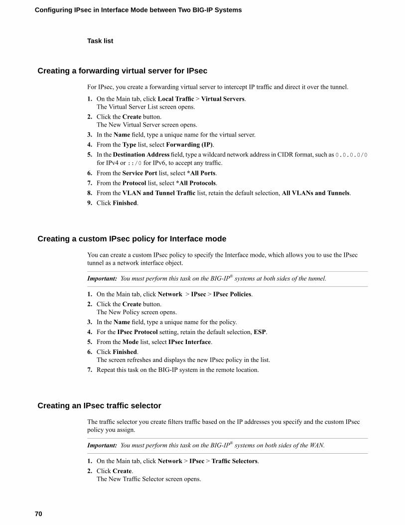
Task list
Creating a forwarding virtual server for IPsec
For IPsec, you create a forwarding virtual server to intercept IP traffic and direct it over the tunnel.
1. On the Main tab, click Local Traffic > Virtual Servers.The Virtual Server List screen opens.
2. Click the Create button.The New Virtual Server screen opens.
3. In the Name field, type a unique name for the virtual server.4. From the Type list, select Forwarding (IP).5. In theDestination Address field, type a wildcard network address in CIDR format, such as 0.0.0.0/0
for IPv4 or ::/0 for IPv6, to accept any traffic.6. From the Service Port list, select *All Ports.7. From the Protocol list, select *All Protocols.8. From the VLAN and Tunnel Traffic list, retain the default selection, All VLANs and Tunnels.9. Click Finished.
Creating a custom IPsec policy for Interface mode
You can create a custom IPsec policy to specify the Interface mode, which allows you to use the IPsectunnel as a network interface object.
Important: You must perform this task on the BIG-IP® systems at both sides of the tunnel.
1. On the Main tab, click Network > IPsec > IPsec Policies.2. Click the Create button.
The New Policy screen opens.3. In the Name field, type a unique name for the policy.4. For the IPsec Protocol setting, retain the default selection, ESP.5. From theMode list, select IPsec Interface.6. Click Finished.
The screen refreshes and displays the new IPsec policy in the list.7. Repeat this task on the BIG-IP system in the remote location.
Creating an IPsec traffic selector
The traffic selector you create filters traffic based on the IP addresses you specify and the custom IPsecpolicy you assign.
Important: You must perform this task on the BIG-IP® systems on both sides of the WAN.
1. On the Main tab, click Network > IPsec > Traffic Selectors.2. Click Create.
The New Traffic Selector screen opens.
70
Configuring IPsec in Interface Mode between Two BIG-IP Systems
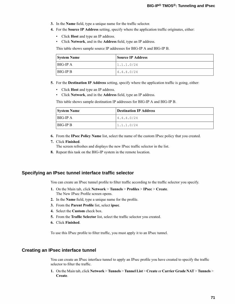
3. In the Name field, type a unique name for the traffic selector.4. For the Source IP Address setting, specify where the application traffic originates, either:
• Click Host and type an IP address.• Click Network, and in the Address field, type an IP address.
This table shows sample source IP addresses for BIG-IP A and BIG-IP B.
Source IP AddressSystem Name
1.1.1.0/24BIG-IP A
4.4.4.0/24BIG-IP B
5. For the Destination IP Address setting, specify where the application traffic is going, either:
• Click Host and type an IP address.• Click Network, and in the Address field, type an IP address.
This table shows sample destination IP addresses for BIG-IP A and BIG-IP B.
Destination IP AddressSystem Name
4.4.4.0/24BIG-IP A
1.1.1.0/24BIG-IP B
6. From the IPsec Policy Name list, select the name of the custom IPsec policy that you created.7. Click Finished.
The screen refreshes and displays the new IPsec traffic selector in the list.8. Repeat this task on the BIG-IP system in the remote location.
Specifying an IPsec tunnel interface traffic selector
You can create an IPsec tunnel profile to filter traffic according to the traffic selector you specify.
1. On the Main tab, click Network > Tunnels > Profiles > IPsec > Create.The New IPsec Profile screen opens.
2. In the Name field, type a unique name for the profile.3. From the Parent Profile list, select ipsec.4. Select the Custom check box.5. From the Traffic Selector list, select the traffic selector you created.6. Click Finished.
To use this IPsec profile to filter traffic, you must apply it to an IPsec tunnel.
Creating an IPsec interface tunnel
You can create an IPsec interface tunnel to apply an IPsec profile you have created to specify the trafficselector to filter the traffic.
1. On theMain tab, clickNetwork >Tunnels >Tunnel List >Create orCarrier Grade NAT >Tunnels >Create.
71
BIG-IP® TMOS®: Tunneling and IPsec
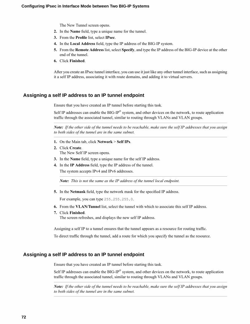
The New Tunnel screen opens.2. In the Name field, type a unique name for the tunnel.3. From the Profile list, select IPsec.4. In the Local Address field, type the IP address of the BIG-IP system.5. From theRemote Address list, select Specify, and type the IP address of the BIG-IP device at the other
end of the tunnel.6. Click Finished.
After you create an IPsec tunnel interface, you can use it just like any other tunnel interface, such as assigningit a self IP address, associating it with route domains, and adding it to virtual servers.
Assigning a self IP address to an IP tunnel endpoint
Ensure that you have created an IP tunnel before starting this task.
Self IP addresses can enable the BIG-IP® system, and other devices on the network, to route applicationtraffic through the associated tunnel, similar to routing through VLANs and VLAN groups.
Note: If the other side of the tunnel needs to be reachable, make sure the self IP addresses that you assignto both sides of the tunnel are in the same subnet.
1. On the Main tab, click Network > Self IPs.2. Click Create.
The New Self IP screen opens.3. In the Name field, type a unique name for the self IP address.4. In the IP Address field, type the IP address of the tunnel.
The system accepts IPv4 and IPv6 addresses.
Note: This is not the same as the IP address of the tunnel local endpoint.
5. In the Netmask field, type the network mask for the specified IP address.
For example, you can type 255.255.255.0.
6. From the VLAN/Tunnel list, select the tunnel with which to associate this self IP address.7. Click Finished.
The screen refreshes, and displays the new self IP address.
Assigning a self IP to a tunnel ensures that the tunnel appears as a resource for routing traffic.
To direct traffic through the tunnel, add a route for which you specify the tunnel as the resource.
Assigning a self IP address to an IP tunnel endpoint
Ensure that you have created an IP tunnel before starting this task.
Self IP addresses can enable the BIG-IP® system, and other devices on the network, to route applicationtraffic through the associated tunnel, similar to routing through VLANs and VLAN groups.
Note: If the other side of the tunnel needs to be reachable, make sure the self IP addresses that you assignto both sides of the tunnel are in the same subnet.
72
Configuring IPsec in Interface Mode between Two BIG-IP Systems
1. On the Main tab, click Network > Self IPs.2. Click Create.
The New Self IP screen opens.3. In the Name field, type a unique name for the self IP address.4. In the IP Address field, type the IP address of the tunnel.
The system accepts IPv4 and IPv6 addresses.
Note: This is not the same as the IP address of the tunnel local endpoint.
5. In the Netmask field, type the network mask for the specified IP address.
For example, you can type 255.255.255.0.
6. From the VLAN/Tunnel list, select the tunnel with which to associate this self IP address.7. Click Finished.
The screen refreshes, and displays the new self IP address.
Assigning a self IP to a tunnel ensures that the tunnel appears as a resource for routing traffic.
To direct traffic through the tunnel, add a route for which you specify the tunnel as the resource.
73
BIG-IP® TMOS®: Tunneling and IPsec

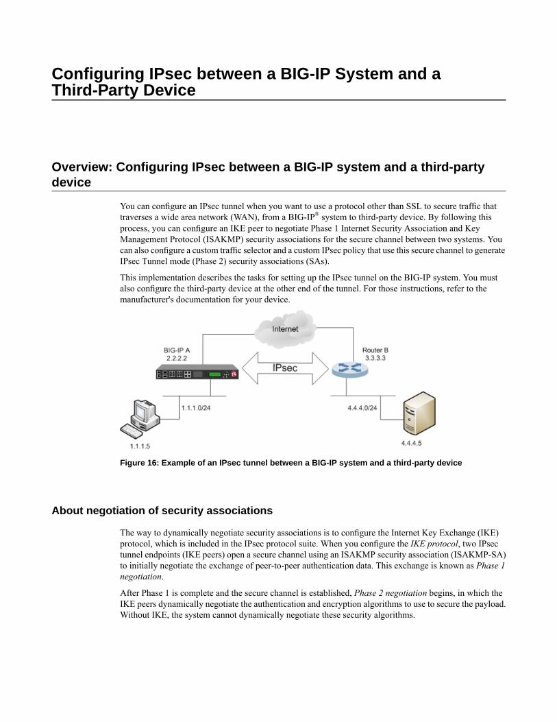
Configuring IPsec between a BIG-IP System and aThird-Party Device
Overview: Configuring IPsec between a BIG-IP system and a third-partydevice
You can configure an IPsec tunnel when you want to use a protocol other than SSL to secure traffic thattraverses a wide area network (WAN), from a BIG-IP® system to third-party device. By following thisprocess, you can configure an IKE peer to negotiate Phase 1 Internet Security Association and KeyManagement Protocol (ISAKMP) security associations for the secure channel between two systems. Youcan also configure a custom traffic selector and a custom IPsec policy that use this secure channel to generateIPsec Tunnel mode (Phase 2) security associations (SAs).
This implementation describes the tasks for setting up the IPsec tunnel on the BIG-IP system. You mustalso configure the third-party device at the other end of the tunnel. For those instructions, refer to themanufacturer's documentation for your device.
Figure 16: Example of an IPsec tunnel between a BIG-IP system and a third-party device
About negotiation of security associations
The way to dynamically negotiate security associations is to configure the Internet Key Exchange (IKE)protocol, which is included in the IPsec protocol suite. When you configure the IKE protocol, two IPsectunnel endpoints (IKE peers) open a secure channel using an ISAKMP security association (ISAKMP-SA)to initially negotiate the exchange of peer-to-peer authentication data. This exchange is known as Phase 1negotiation.
After Phase 1 is complete and the secure channel is established, Phase 2 negotiation begins, in which theIKE peers dynamically negotiate the authentication and encryption algorithms to use to secure the payload.Without IKE, the system cannot dynamically negotiate these security algorithms.
About IPsec Tunnel mode
Tunnel mode causes the IPsec protocol to encrypt the entire packet (the payload plus the IP header). Thisencrypted packet is then included as the payload in another outer packet with a new header. Traffic sent inthis mode is more secure than traffic sent in Transport mode, because the original IP header is encryptedalong with the original payload.
About BIG-IP components of the IPsec protocol suite
The IPsec protocol suite on the BIG-IP® system consists of these configuration components:
IKE peersAn IKE peer is a configuration object of the IPsec protocol suite that represents a BIG-IP system oneach side of the IPsec tunnel. IKE peers allow two systems to authenticate each other (known as IKEPhase 1). The BIG-IP system supports two versions of the IKE protocol: Version 1 (IKEv1) and Version2 (IKEv2). The BIG-IP system includes the default IKE peer, named anonymous, which is configuredto use Version 1.
Note: The BIG-IP system currently supports IKEv2 only in Tunnel mode, and does not support IPCompor NAT-T with IKEv2.
IPsec policiesAn IPsec policy is a set of information that defines the specific IPsec protocol to use (ESP or AH), andthe mode (Transport, Tunnel, or iSession). For Tunnel mode, the policy also specifies the endpoints forthe tunnel, and for IKE Phase 2 negotiation, the policy specifies the security parameters to be used inthat negotiation. The way that you configure the IPsec policy determines the way that the BIG-IP systemmanipulates the IP headers in the packets. The BIG-IP system includes two default IPsec policies, nameddefault-ipsec-policy and default-ipsec-policy-isession. A common configurationincludes a bidirectional policy on each BIG-IP system.
Traffic selectorsA traffic selector is a packet filter that defines what traffic should be handled by a IPsec policy. Youdefine the traffic by source and destination IP addresses and port numbers. A common configurationincludes a bidirectional traffic selector on each BIG-IP system.
Task summary
You can configure the IPsec and IKE protocols to secure traffic that traverses a wide area network (WAN),such as from one data center to another.
Before you begin configuring IPsec and IKE, verify that this module, system objects, and connectivity existon the BIG-IP® system:
BIG-IP Local Traffic Manager™
This module directs traffic securely and efficiently to the appropriate destination on a network.
Self IP addressThe BIG-IP system must have at least one self IP address, to be used in specifying the end of the IPsectunnel.
76
Configuring IPsec between a BIG-IP System and a Third-Party Device
The default VLANsThese VLANs are named external and internal.
BIG-IP connectivityVerify the connectivity between the client or server and its BIG-IP device, and between the BIG-IPdevice and its gateway. For example, you can use ping to test this connectivity.
Task list
Creating a forwarding virtual server for IPsec
For IPsec, you create a forwarding virtual server to intercept IP traffic and direct it over the tunnel.
1. On the Main tab, click Local Traffic > Virtual Servers.The Virtual Server List screen opens.
2. Click the Create button.The New Virtual Server screen opens.
3. In the Name field, type a unique name for the virtual server.4. From the Type list, select Forwarding (IP).5. In theDestination Address field, type a wildcard network address in CIDR format, such as 0.0.0.0/0
for IPv4 or ::/0 for IPv6, to accept any traffic.6. From the Service Port list, select *All Ports.7. From the Protocol list, select *All Protocols.8. From the VLAN and Tunnel Traffic list, retain the default selection, All VLANs and Tunnels.9. Click Finished.
Creating an IKE peer
The IKE peer object identifies to the system you are configuring the other device with which it communicatesduring Phase 1 negotiations. The IKE peer object also specifies the specific algorithms and credentials tobe used for Phase 1 negotiation.
Important: You must also configure the device at the other end of the IPsec tunnel.
1. On the Main tab, click Network > IPsec > IKE Peers.2. Click the Create button.
The New IKE Peer screen opens.3. In the Name field, type a unique name for the IKE peer.4. In the Description field, type a brief description of the IKE peer.5. In the Remote Address field, type the IP address of the device that is remote to the system you are
configuring.This address must match the value of the Tunnel Remote Address setting in the relevant IPsec policy.
6. For the State setting, retain the default value, Enabled.7. For the IKE Phase 1 Algorithms area, retain the default values, or select the options that are appropriate
for your deployment.
Important: The values you select must match the IKE Phase 1 settings on the remote device.
77
BIG-IP® TMOS®: Tunneling and IPsec
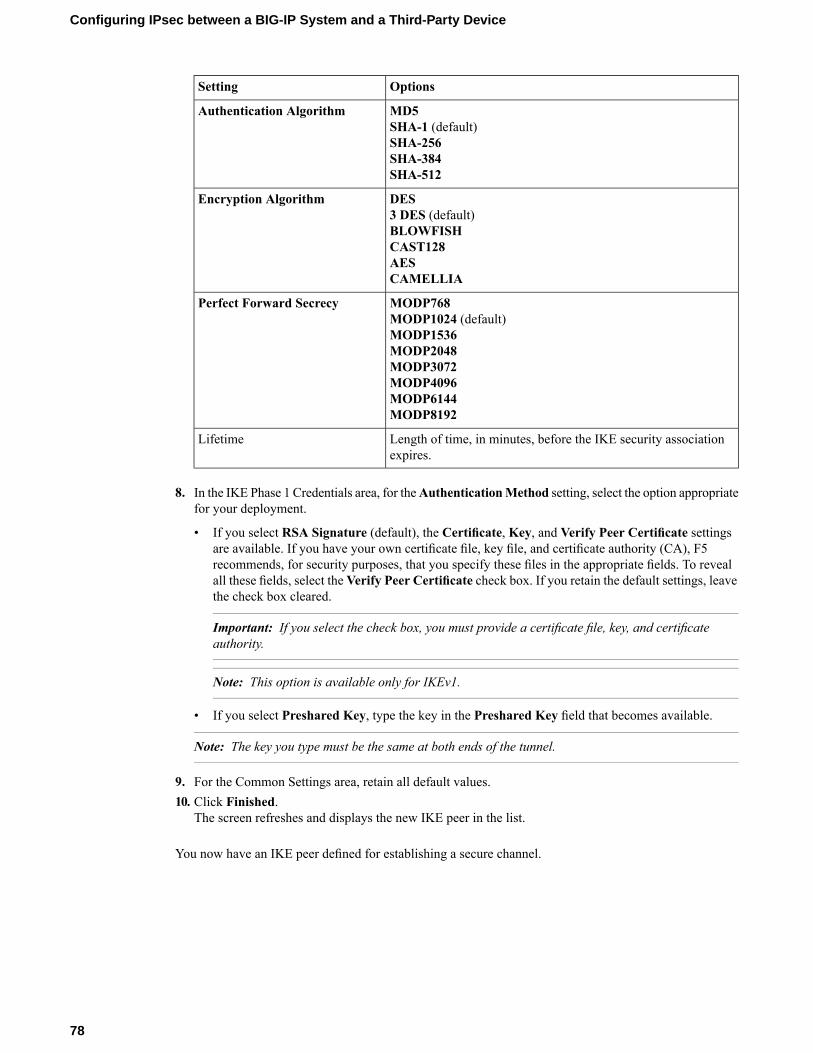
OptionsSetting
MD5Authentication AlgorithmSHA-1 (default)SHA-256SHA-384SHA-512
DESEncryption Algorithm3 DES (default)BLOWFISHCAST128AESCAMELLIA
MODP768Perfect Forward SecrecyMODP1024 (default)MODP1536MODP2048MODP3072MODP4096MODP6144MODP8192
Length of time, in minutes, before the IKE security associationexpires.
Lifetime
8. In the IKE Phase 1 Credentials area, for theAuthenticationMethod setting, select the option appropriatefor your deployment.
• If you select RSA Signature (default), the Certificate, Key, and Verify Peer Certificate settingsare available. If you have your own certificate file, key file, and certificate authority (CA), F5recommends, for security purposes, that you specify these files in the appropriate fields. To revealall these fields, select theVerify Peer Certificate check box. If you retain the default settings, leavethe check box cleared.
Important: If you select the check box, you must provide a certificate file, key, and certificateauthority.
Note: This option is available only for IKEv1.
• If you select Preshared Key, type the key in the Preshared Key field that becomes available.
Note: The key you type must be the same at both ends of the tunnel.
9. For the Common Settings area, retain all default values.10. Click Finished.
The screen refreshes and displays the new IKE peer in the list.
You now have an IKE peer defined for establishing a secure channel.
78
Configuring IPsec between a BIG-IP System and a Third-Party Device
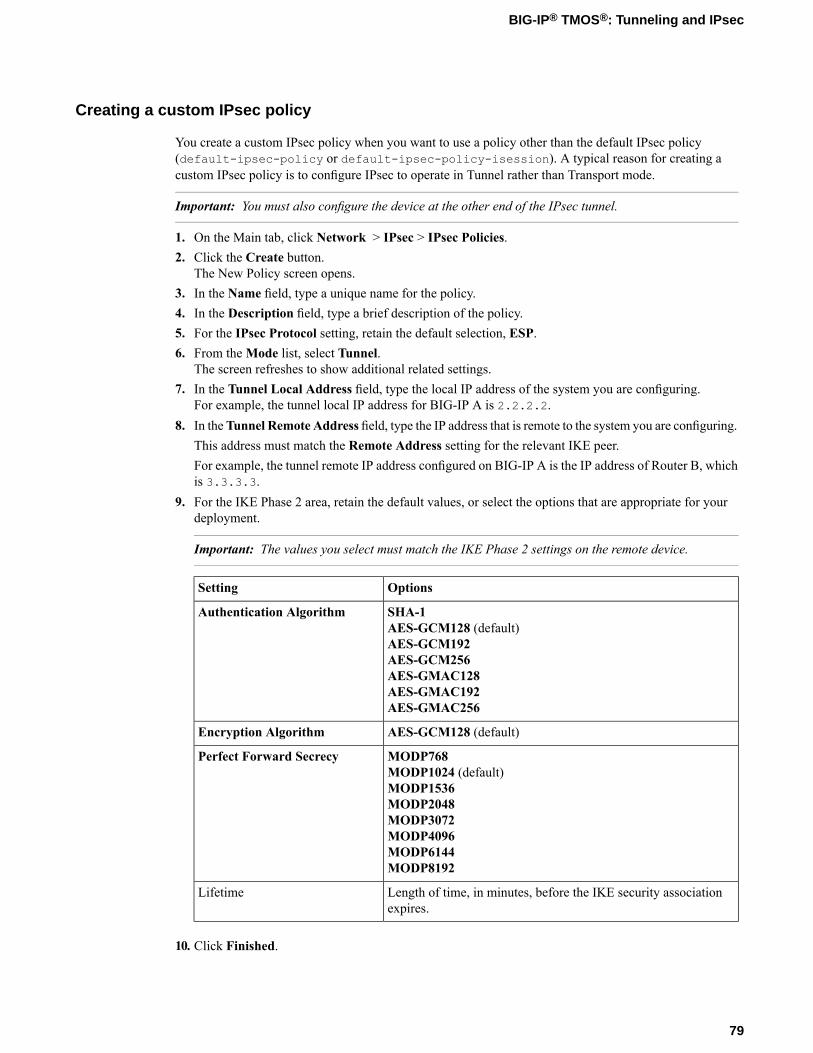
Creating a custom IPsec policy
You create a custom IPsec policy when you want to use a policy other than the default IPsec policy(default-ipsec-policy or default-ipsec-policy-isession). A typical reason for creating acustom IPsec policy is to configure IPsec to operate in Tunnel rather than Transport mode.
Important: You must also configure the device at the other end of the IPsec tunnel.
1. On the Main tab, click Network > IPsec > IPsec Policies.2. Click the Create button.
The New Policy screen opens.3. In the Name field, type a unique name for the policy.4. In the Description field, type a brief description of the policy.5. For the IPsec Protocol setting, retain the default selection, ESP.6. From theMode list, select Tunnel.
The screen refreshes to show additional related settings.7. In the Tunnel Local Address field, type the local IP address of the system you are configuring.
For example, the tunnel local IP address for BIG-IP A is 2.2.2.2.8. In theTunnel Remote Address field, type the IP address that is remote to the system you are configuring.
This address must match the Remote Address setting for the relevant IKE peer.For example, the tunnel remote IP address configured on BIG-IP A is the IP address of Router B, whichis 3.3.3.3.
9. For the IKE Phase 2 area, retain the default values, or select the options that are appropriate for yourdeployment.
Important: The values you select must match the IKE Phase 2 settings on the remote device.
OptionsSetting
SHA-1Authentication AlgorithmAES-GCM128 (default)AES-GCM192AES-GCM256AES-GMAC128AES-GMAC192AES-GMAC256
AES-GCM128 (default)Encryption Algorithm
MODP768Perfect Forward SecrecyMODP1024 (default)MODP1536MODP2048MODP3072MODP4096MODP6144MODP8192
Length of time, in minutes, before the IKE security associationexpires.
Lifetime
10. Click Finished.
79
BIG-IP® TMOS®: Tunneling and IPsec
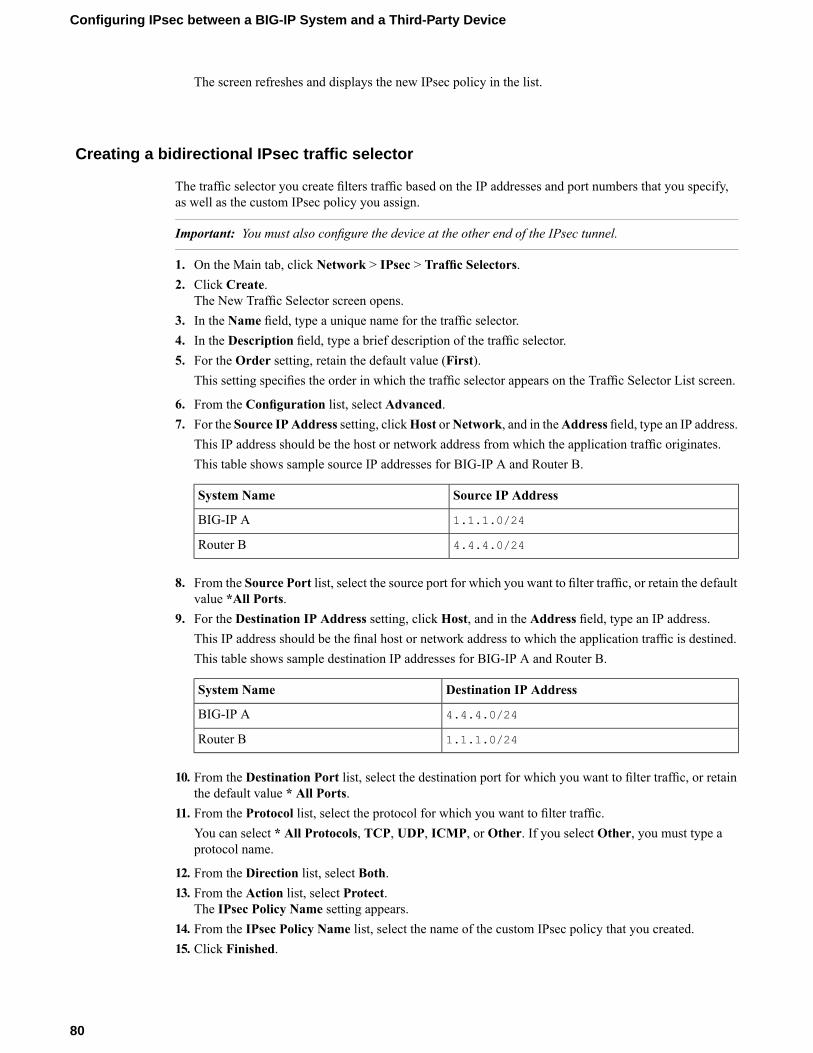
The screen refreshes and displays the new IPsec policy in the list.
Creating a bidirectional IPsec traffic selector
The traffic selector you create filters traffic based on the IP addresses and port numbers that you specify,as well as the custom IPsec policy you assign.
Important: You must also configure the device at the other end of the IPsec tunnel.
1. On the Main tab, click Network > IPsec > Traffic Selectors.2. Click Create.
The New Traffic Selector screen opens.3. In the Name field, type a unique name for the traffic selector.4. In the Description field, type a brief description of the traffic selector.5. For the Order setting, retain the default value (First).
This setting specifies the order in which the traffic selector appears on the Traffic Selector List screen.
6. From the Configuration list, select Advanced.7. For the Source IP Address setting, clickHost orNetwork, and in theAddress field, type an IP address.
This IP address should be the host or network address from which the application traffic originates.This table shows sample source IP addresses for BIG-IP A and Router B.
Source IP AddressSystem Name
1.1.1.0/24BIG-IP A
4.4.4.0/24Router B
8. From the Source Port list, select the source port for which you want to filter traffic, or retain the defaultvalue *All Ports.
9. For the Destination IP Address setting, click Host, and in the Address field, type an IP address.This IP address should be the final host or network address to which the application traffic is destined.This table shows sample destination IP addresses for BIG-IP A and Router B.
Destination IP AddressSystem Name
4.4.4.0/24BIG-IP A
1.1.1.0/24Router B
10. From the Destination Port list, select the destination port for which you want to filter traffic, or retainthe default value * All Ports.
11. From the Protocol list, select the protocol for which you want to filter traffic.You can select * All Protocols, TCP, UDP, ICMP, or Other. If you select Other, you must type aprotocol name.
12. From the Direction list, select Both.13. From the Action list, select Protect.
The IPsec Policy Name setting appears.14. From the IPsec Policy Name list, select the name of the custom IPsec policy that you created.15. Click Finished.
80
Configuring IPsec between a BIG-IP System and a Third-Party Device
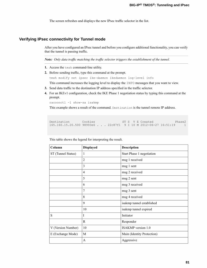
The screen refreshes and displays the new IPsec traffic selector in the list.
Verifying IPsec connectivity for Tunnel mode
After you have configured an IPsec tunnel and before you configure additional functionality, you can verifythat the tunnel is passing traffic.
Note: Only data traffic matching the traffic selector triggers the establishment of the tunnel.
1. Access the tmsh command-line utility.2. Before sending traffic, type this command at the prompt.
tmsh modify net ipsec ike-daemon ikedaemon log-level info
This command increases the logging level to display the INFO messages that you want to view.3. Send data traffic to the destination IP address specified in the traffic selector.4. For an IKEv1 configuration, check the IKE Phase 1 negotiation status by typing this command at the
prompt.racoonctl -l show-sa isakmp
This example shows a result of the command. Destination is the tunnel remote IP address.
Destination Cookies ST S V E Created Phase2165.160.15.20.500 98993e6 . . . 22c87f1 9 I 10 M 2012-06-27 16:51:19 1
This table shows the legend for interpreting the result.
DescriptionDisplayedColumn
Start Phase 1 negotiation1ST (Tunnel Status)
msg 1 received2
msg 1 sent3
msg 2 received4
msg 2 sent5
msg 3 received6
msg 3 sent7
msg 4 received8
isakmp tunnel established9
isakmp tunnel expired10
InitiatorIS
ResponderR
ISAKMP version 1.010V (Version Number)
Main (Identity Protection)ME (Exchange Mode)
AggressiveA
81
BIG-IP® TMOS®: Tunneling and IPsec
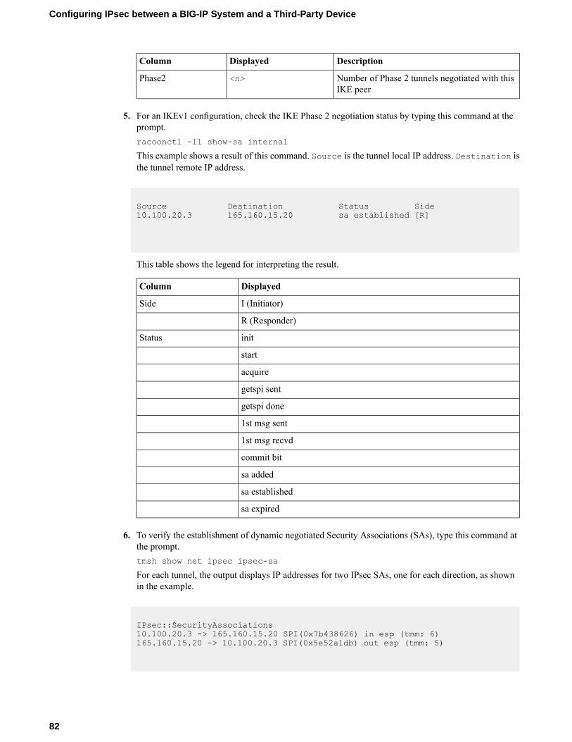
DescriptionDisplayedColumn
Number of Phase 2 tunnels negotiated with thisIKE peer
<n>Phase2
5. For an IKEv1 configuration, check the IKE Phase 2 negotiation status by typing this command at theprompt.racoonctl -ll show-sa internal
This example shows a result of this command. Source is the tunnel local IP address. Destination isthe tunnel remote IP address.
Source Destination Status Side10.100.20.3 165.160.15.20 sa established [R]
This table shows the legend for interpreting the result.
DisplayedColumn
I (Initiator)Side
R (Responder)
initStatus
start
acquire
getspi sent
getspi done
1st msg sent
1st msg recvd
commit bit
sa added
sa established
sa expired
6. To verify the establishment of dynamic negotiated Security Associations (SAs), type this command atthe prompt.tmsh show net ipsec ipsec-sa
For each tunnel, the output displays IP addresses for two IPsec SAs, one for each direction, as shownin the example.
IPsec::SecurityAssociations10.100.20.3 -> 165.160.15.20 SPI(0x7b438626) in esp (tmm: 6)165.160.15.20 -> 10.100.20.3 SPI(0x5e52a1db) out esp (tmm: 5)
82
Configuring IPsec between a BIG-IP System and a Third-Party Device
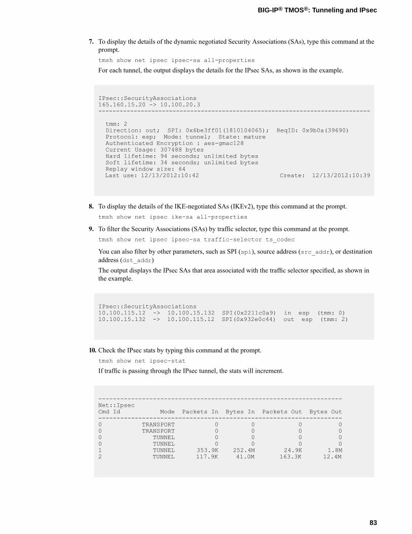
7. To display the details of the dynamic negotiated Security Associations (SAs), type this command at theprompt.tmsh show net ipsec ipsec-sa all-properties
For each tunnel, the output displays the details for the IPsec SAs, as shown in the example.
IPsec::SecurityAssociations165.160.15.20 -> 10.100.20.3-----------------------------------------------------------------------------
tmm: 2Direction: out; SPI: 0x6be3ff01(1810104065); ReqID: 0x9b0a(39690)Protocol: esp; Mode: tunnel; State: matureAuthenticated Encryption : aes-gmac128Current Usage: 307488 bytesHard lifetime: 94 seconds; unlimited bytesSoft lifetime: 34 seconds; unlimited bytesReplay window size: 64Last use: 12/13/2012:10:42 Create: 12/13/2012:10:39
8. To display the details of the IKE-negotiated SAs (IKEv2), type this command at the prompt.tmsh show net ipsec ike-sa all-properties
9. To filter the Security Associations (SAs) by traffic selector, type this command at the prompt.tmsh show net ipsec ipsec-sa traffic-selector ts_codec
You can also filter by other parameters, such as SPI (spi), source address (src_addr), or destinationaddress (dst_addr)The output displays the IPsec SAs that area associated with the traffic selector specified, as shown inthe example.
IPsec::SecurityAssociations10.100.115.12 -> 10.100.15.132 SPI(0x2211c0a9) in esp (tmm: 0)10.100.15.132 -> 10.100.115.12 SPI(0x932e0c44) out esp (tmm: 2)
10. Check the IPsec stats by typing this command at the prompt.tmsh show net ipsec-stat
If traffic is passing through the IPsec tunnel, the stats will increment.
-------------------------------------------------------------------Net::IpsecCmd Id Mode Packets In Bytes In Packets Out Bytes Out-------------------------------------------------------------------0 TRANSPORT 0 0 0 00 TRANSPORT 0 0 0 00 TUNNEL 0 0 0 00 TUNNEL 0 0 0 01 TUNNEL 353.9K 252.4M 24.9K 1.8M2 TUNNEL 117.9K 41.0M 163.3K 12.4M
83
BIG-IP® TMOS®: Tunneling and IPsec
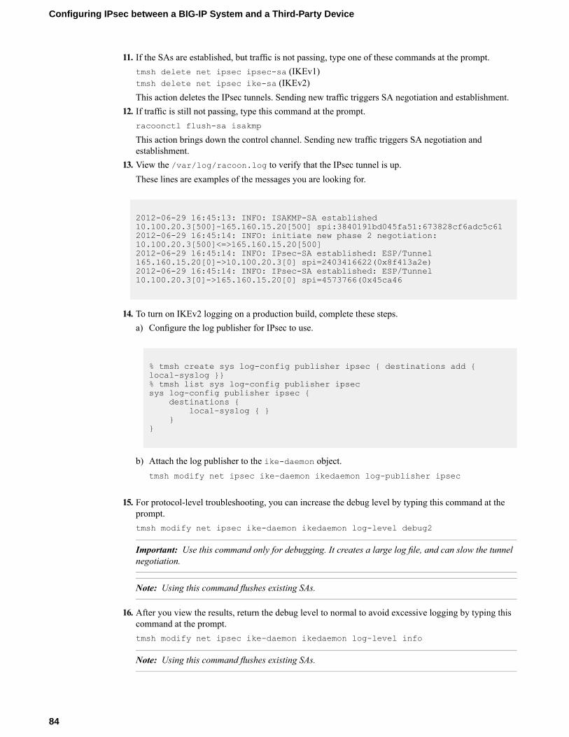
11. If the SAs are established, but traffic is not passing, type one of these commands at the prompt.tmsh delete net ipsec ipsec-sa (IKEv1)tmsh delete net ipsec ike-sa (IKEv2)This action deletes the IPsec tunnels. Sending new traffic triggers SA negotiation and establishment.
12. If traffic is still not passing, type this command at the prompt.racoonctl flush-sa isakmp
This action brings down the control channel. Sending new traffic triggers SA negotiation andestablishment.
13. View the /var/log/racoon.log to verify that the IPsec tunnel is up.These lines are examples of the messages you are looking for.
2012-06-29 16:45:13: INFO: ISAKMP-SA established10.100.20.3[500]-165.160.15.20[500] spi:3840191bd045fa51:673828cf6adc5c612012-06-29 16:45:14: INFO: initiate new phase 2 negotiation:10.100.20.3[500]<=>165.160.15.20[500]2012-06-29 16:45:14: INFO: IPsec-SA established: ESP/Tunnel165.160.15.20[0]->10.100.20.3[0] spi=2403416622(0x8f413a2e)2012-06-29 16:45:14: INFO: IPsec-SA established: ESP/Tunnel10.100.20.3[0]->165.160.15.20[0] spi=4573766(0x45ca46
14. To turn on IKEv2 logging on a production build, complete these steps.a) Configure the log publisher for IPsec to use.
% tmsh create sys log-config publisher ipsec { destinations add {local-syslog }}% tmsh list sys log-config publisher ipsecsys log-config publisher ipsec {
destinations {local-syslog { }
}}
b) Attach the log publisher to the ike-daemon object.tmsh modify net ipsec ike-daemon ikedaemon log-publisher ipsec
15. For protocol-level troubleshooting, you can increase the debug level by typing this command at theprompt.tmsh modify net ipsec ike-daemon ikedaemon log-level debug2
Important: Use this command only for debugging. It creates a large log file, and can slow the tunnelnegotiation.
Note: Using this command flushes existing SAs.
16. After you view the results, return the debug level to normal to avoid excessive logging by typing thiscommand at the prompt.tmsh modify net ipsec ike-daemon ikedaemon log-level info
Note: Using this command flushes existing SAs.
84
Configuring IPsec between a BIG-IP System and a Third-Party Device

Implementation result
You now have an IPsec tunnel for securing traffic that traverses the WAN, from one BIG-IP® system to athird-party device.
85
BIG-IP® TMOS®: Tunneling and IPsec

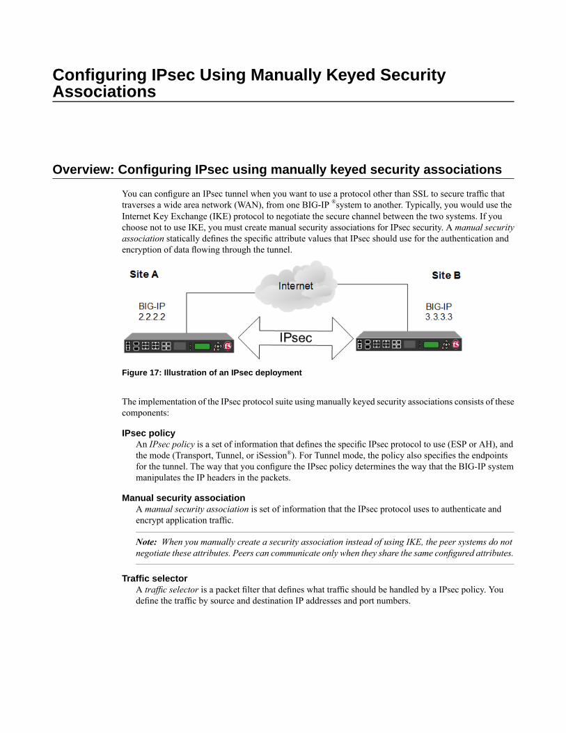
Configuring IPsec Using Manually Keyed SecurityAssociations
Overview: Configuring IPsec using manually keyed security associations
You can configure an IPsec tunnel when you want to use a protocol other than SSL to secure traffic thattraverses a wide area network (WAN), from one BIG-IP ®system to another. Typically, you would use theInternet Key Exchange (IKE) protocol to negotiate the secure channel between the two systems. If youchoose not to use IKE, you must create manual security associations for IPsec security. A manual securityassociation statically defines the specific attribute values that IPsec should use for the authentication andencryption of data flowing through the tunnel.
Figure 17: Illustration of an IPsec deployment
The implementation of the IPsec protocol suite using manually keyed security associations consists of thesecomponents:
IPsec policyAn IPsec policy is a set of information that defines the specific IPsec protocol to use (ESP or AH), andthe mode (Transport, Tunnel, or iSession®). For Tunnel mode, the policy also specifies the endpointsfor the tunnel. The way that you configure the IPsec policy determines the way that the BIG-IP systemmanipulates the IP headers in the packets.
Manual security associationA manual security association is set of information that the IPsec protocol uses to authenticate andencrypt application traffic.
Note: When you manually create a security association instead of using IKE, the peer systems do notnegotiate these attributes. Peers can communicate only when they share the same configured attributes.
Traffic selectorA traffic selector is a packet filter that defines what traffic should be handled by a IPsec policy. Youdefine the traffic by source and destination IP addresses and port numbers.
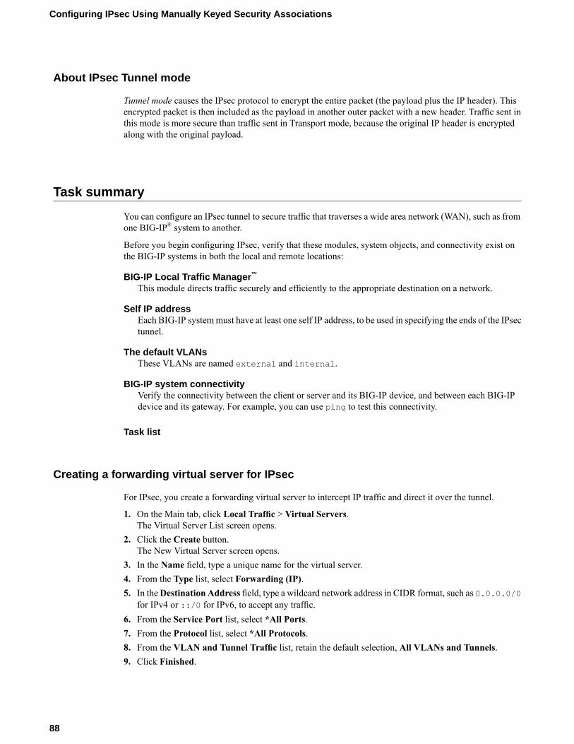
About IPsec Tunnel mode
Tunnel mode causes the IPsec protocol to encrypt the entire packet (the payload plus the IP header). Thisencrypted packet is then included as the payload in another outer packet with a new header. Traffic sent inthis mode is more secure than traffic sent in Transport mode, because the original IP header is encryptedalong with the original payload.
Task summary
You can configure an IPsec tunnel to secure traffic that traverses a wide area network (WAN), such as fromone BIG-IP® system to another.
Before you begin configuring IPsec, verify that these modules, system objects, and connectivity exist onthe BIG-IP systems in both the local and remote locations:
BIG-IP Local Traffic Manager™
This module directs traffic securely and efficiently to the appropriate destination on a network.
Self IP addressEach BIG-IP systemmust have at least one self IP address, to be used in specifying the ends of the IPsectunnel.
The default VLANsThese VLANs are named external and internal.
BIG-IP system connectivityVerify the connectivity between the client or server and its BIG-IP device, and between each BIG-IPdevice and its gateway. For example, you can use ping to test this connectivity.
Task list
Creating a forwarding virtual server for IPsec
For IPsec, you create a forwarding virtual server to intercept IP traffic and direct it over the tunnel.
1. On the Main tab, click Local Traffic > Virtual Servers.The Virtual Server List screen opens.
2. Click the Create button.The New Virtual Server screen opens.
3. In the Name field, type a unique name for the virtual server.4. From the Type list, select Forwarding (IP).5. In theDestination Address field, type a wildcard network address in CIDR format, such as 0.0.0.0/0
for IPv4 or ::/0 for IPv6, to accept any traffic.6. From the Service Port list, select *All Ports.7. From the Protocol list, select *All Protocols.8. From the VLAN and Tunnel Traffic list, retain the default selection, All VLANs and Tunnels.9. Click Finished.
88
Configuring IPsec Using Manually Keyed Security Associations
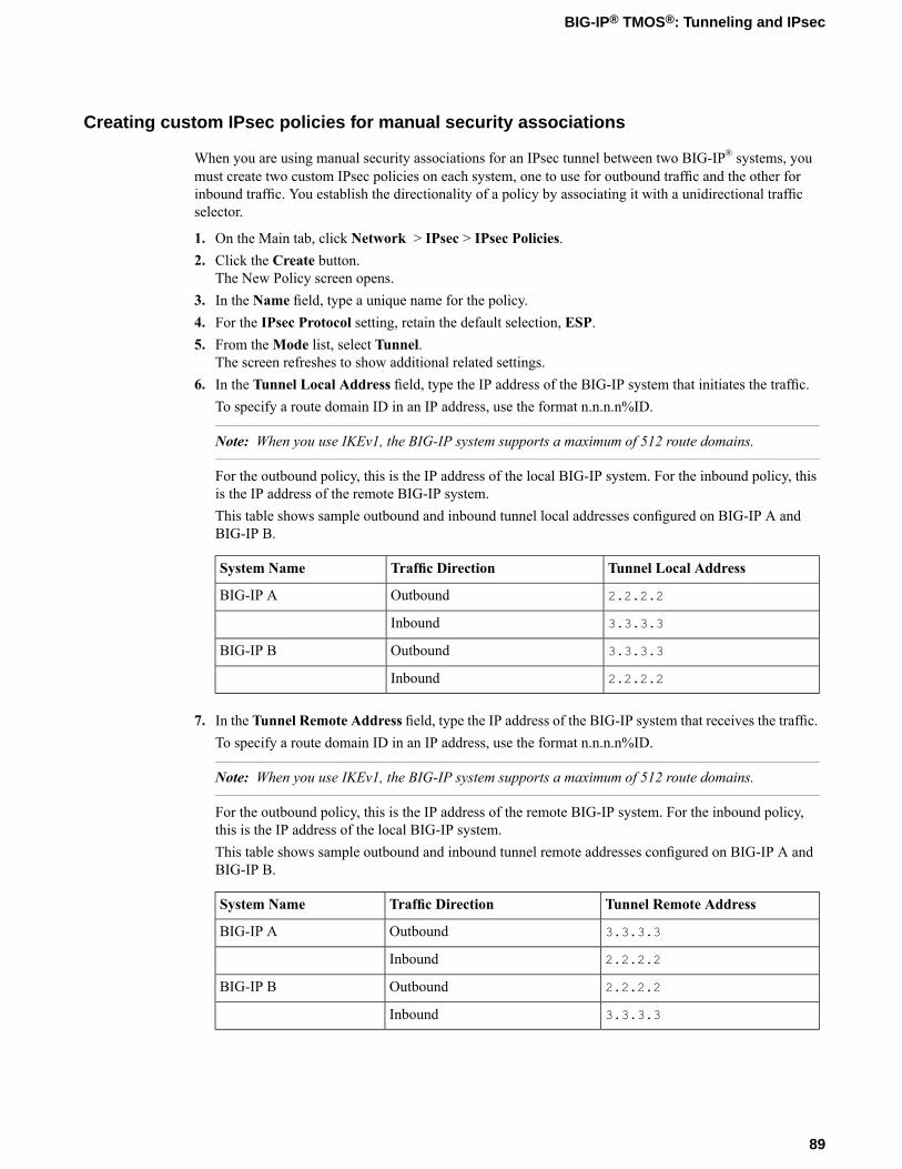
Creating custom IPsec policies for manual security associations
When you are using manual security associations for an IPsec tunnel between two BIG-IP® systems, youmust create two custom IPsec policies on each system, one to use for outbound traffic and the other forinbound traffic. You establish the directionality of a policy by associating it with a unidirectional trafficselector.
1. On the Main tab, click Network > IPsec > IPsec Policies.2. Click the Create button.
The New Policy screen opens.3. In the Name field, type a unique name for the policy.4. For the IPsec Protocol setting, retain the default selection, ESP.5. From theMode list, select Tunnel.
The screen refreshes to show additional related settings.6. In the Tunnel Local Address field, type the IP address of the BIG-IP system that initiates the traffic.
To specify a route domain ID in an IP address, use the format n.n.n.n%ID.
Note: When you use IKEv1, the BIG-IP system supports a maximum of 512 route domains.
For the outbound policy, this is the IP address of the local BIG-IP system. For the inbound policy, thisis the IP address of the remote BIG-IP system.This table shows sample outbound and inbound tunnel local addresses configured on BIG-IP A andBIG-IP B.
Tunnel Local AddressTraffic DirectionSystem Name
2.2.2.2OutboundBIG-IP A
3.3.3.3Inbound
3.3.3.3OutboundBIG-IP B
2.2.2.2Inbound
7. In the Tunnel Remote Address field, type the IP address of the BIG-IP system that receives the traffic.To specify a route domain ID in an IP address, use the format n.n.n.n%ID.
Note: When you use IKEv1, the BIG-IP system supports a maximum of 512 route domains.
For the outbound policy, this is the IP address of the remote BIG-IP system. For the inbound policy,this is the IP address of the local BIG-IP system.This table shows sample outbound and inbound tunnel remote addresses configured on BIG-IP A andBIG-IP B.
Tunnel Remote AddressTraffic DirectionSystem Name
3.3.3.3OutboundBIG-IP A
2.2.2.2Inbound
2.2.2.2OutboundBIG-IP B
3.3.3.3Inbound
89
BIG-IP® TMOS®: Tunneling and IPsec
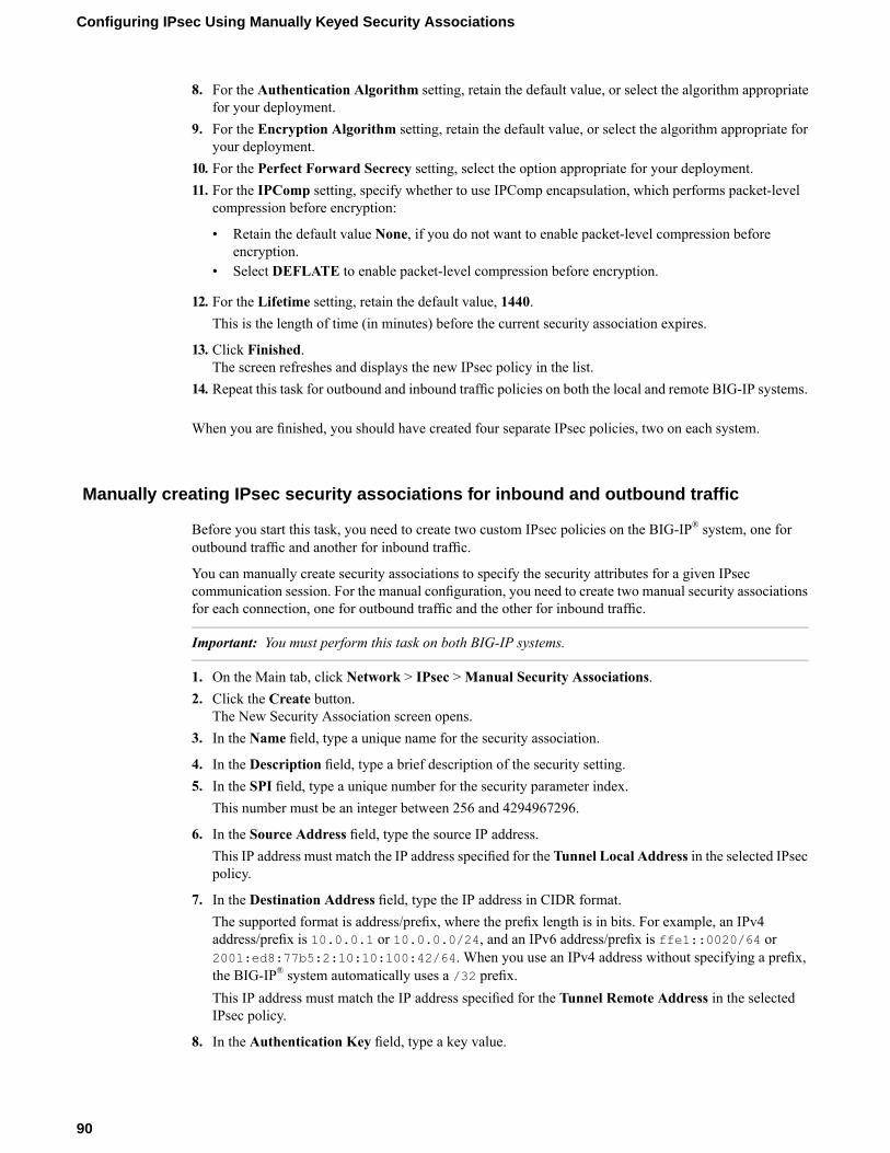
8. For the Authentication Algorithm setting, retain the default value, or select the algorithm appropriatefor your deployment.
9. For the Encryption Algorithm setting, retain the default value, or select the algorithm appropriate foryour deployment.
10. For the Perfect Forward Secrecy setting, select the option appropriate for your deployment.11. For the IPComp setting, specify whether to use IPComp encapsulation, which performs packet-level
compression before encryption:
• Retain the default value None, if you do not want to enable packet-level compression beforeencryption.
• Select DEFLATE to enable packet-level compression before encryption.
12. For the Lifetime setting, retain the default value, 1440.This is the length of time (in minutes) before the current security association expires.
13. Click Finished.The screen refreshes and displays the new IPsec policy in the list.
14. Repeat this task for outbound and inbound traffic policies on both the local and remote BIG-IP systems.
When you are finished, you should have created four separate IPsec policies, two on each system.
Manually creating IPsec security associations for inbound and outbound traffic
Before you start this task, you need to create two custom IPsec policies on the BIG-IP® system, one foroutbound traffic and another for inbound traffic.
You can manually create security associations to specify the security attributes for a given IPseccommunication session. For the manual configuration, you need to create two manual security associationsfor each connection, one for outbound traffic and the other for inbound traffic.
Important: You must perform this task on both BIG-IP systems.
1. On the Main tab, click Network > IPsec >Manual Security Associations.2. Click the Create button.
The New Security Association screen opens.3. In the Name field, type a unique name for the security association.
4. In the Description field, type a brief description of the security setting.5. In the SPI field, type a unique number for the security parameter index.
This number must be an integer between 256 and 4294967296.
6. In the Source Address field, type the source IP address.This IP address must match the IP address specified for the Tunnel Local Address in the selected IPsecpolicy.
7. In the Destination Address field, type the IP address in CIDR format.The supported format is address/prefix, where the prefix length is in bits. For example, an IPv4address/prefix is 10.0.0.1 or 10.0.0.0/24, and an IPv6 address/prefix is ffe1::0020/64 or2001:ed8:77b5:2:10:10:100:42/64. When you use an IPv4 address without specifying a prefix,the BIG-IP® system automatically uses a /32 prefix.This IP address must match the IP address specified for the Tunnel Remote Address in the selectedIPsec policy.
8. In the Authentication Key field, type a key value.
90
Configuring IPsec Using Manually Keyed Security Associations
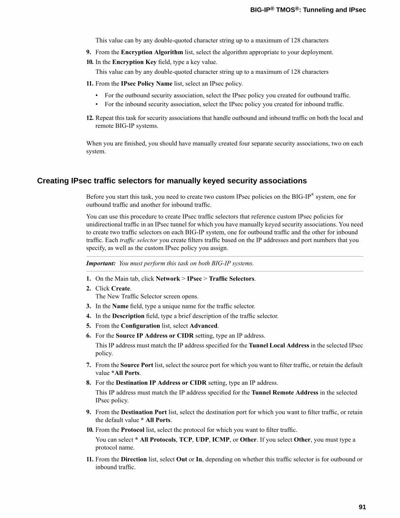
This value can by any double-quoted character string up to a maximum of 128 characters
9. From the Encryption Algorithm list, select the algorithm appropriate to your deployment.10. In the Encryption Key field, type a key value.
This value can by any double-quoted character string up to a maximum of 128 characters
11. From the IPsec Policy Name list, select an IPsec policy.
• For the outbound security association, select the IPsec policy you created for outbound traffic.• For the inbound security association, select the IPsec policy you created for inbound traffic.
12. Repeat this task for security associations that handle outbound and inbound traffic on both the local andremote BIG-IP systems.
When you are finished, you should have manually created four separate security associations, two on eachsystem.
Creating IPsec traffic selectors for manually keyed security associations
Before you start this task, you need to create two custom IPsec policies on the BIG-IP® system, one foroutbound traffic and another for inbound traffic.
You can use this procedure to create IPsec traffic selectors that reference custom IPsec policies forunidirectional traffic in an IPsec tunnel for which you have manually keyed security associations. You needto create two traffic selectors on each BIG-IP system, one for outbound traffic and the other for inboundtraffic. Each traffic selector you create filters traffic based on the IP addresses and port numbers that youspecify, as well as the custom IPsec policy you assign.
Important: You must perform this task on both BIG-IP systems.
1. On the Main tab, click Network > IPsec > Traffic Selectors.2. Click Create.
The New Traffic Selector screen opens.3. In the Name field, type a unique name for the traffic selector.4. In the Description field, type a brief description of the traffic selector.5. From the Configuration list, select Advanced.6. For the Source IP Address or CIDR setting, type an IP address.
This IP address must match the IP address specified for the Tunnel Local Address in the selected IPsecpolicy.
7. From the Source Port list, select the source port for which you want to filter traffic, or retain the defaultvalue *All Ports.
8. For the Destination IP Address or CIDR setting, type an IP address.This IP address must match the IP address specified for the Tunnel Remote Address in the selectedIPsec policy.
9. From the Destination Port list, select the destination port for which you want to filter traffic, or retainthe default value * All Ports.
10. From the Protocol list, select the protocol for which you want to filter traffic.You can select * All Protocols, TCP, UDP, ICMP, or Other. If you select Other, you must type aprotocol name.
11. From the Direction list, select Out or In, depending on whether this traffic selector is for outbound orinbound traffic.
91
BIG-IP® TMOS®: Tunneling and IPsec
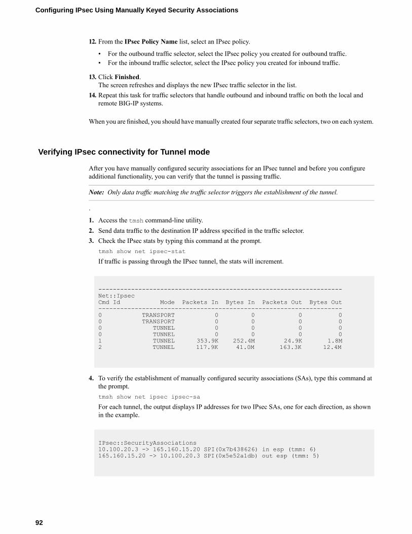
12. From the IPsec Policy Name list, select an IPsec policy.
• For the outbound traffic selector, select the IPsec policy you created for outbound traffic.• For the inbound traffic selector, select the IPsec policy you created for inbound traffic.
13. Click Finished.The screen refreshes and displays the new IPsec traffic selector in the list.
14. Repeat this task for traffic selectors that handle outbound and inbound traffic on both the local andremote BIG-IP systems.
When you are finished, you should have manually created four separate traffic selectors, two on each system.
Verifying IPsec connectivity for Tunnel mode
After you have manually configured security associations for an IPsec tunnel and before you configureadditional functionality, you can verify that the tunnel is passing traffic.
Note: Only data traffic matching the traffic selector triggers the establishment of the tunnel.
.
1. Access the tmsh command-line utility.2. Send data traffic to the destination IP address specified in the traffic selector.3. Check the IPsec stats by typing this command at the prompt.
tmsh show net ipsec-stat
If traffic is passing through the IPsec tunnel, the stats will increment.
-------------------------------------------------------------------Net::IpsecCmd Id Mode Packets In Bytes In Packets Out Bytes Out-------------------------------------------------------------------0 TRANSPORT 0 0 0 00 TRANSPORT 0 0 0 00 TUNNEL 0 0 0 00 TUNNEL 0 0 0 01 TUNNEL 353.9K 252.4M 24.9K 1.8M2 TUNNEL 117.9K 41.0M 163.3K 12.4M
4. To verify the establishment of manually configured security associations (SAs), type this command atthe prompt.tmsh show net ipsec ipsec-sa
For each tunnel, the output displays IP addresses for two IPsec SAs, one for each direction, as shownin the example.
IPsec::SecurityAssociations10.100.20.3 -> 165.160.15.20 SPI(0x7b438626) in esp (tmm: 6)165.160.15.20 -> 10.100.20.3 SPI(0x5e52a1db) out esp (tmm: 5)
92
Configuring IPsec Using Manually Keyed Security Associations
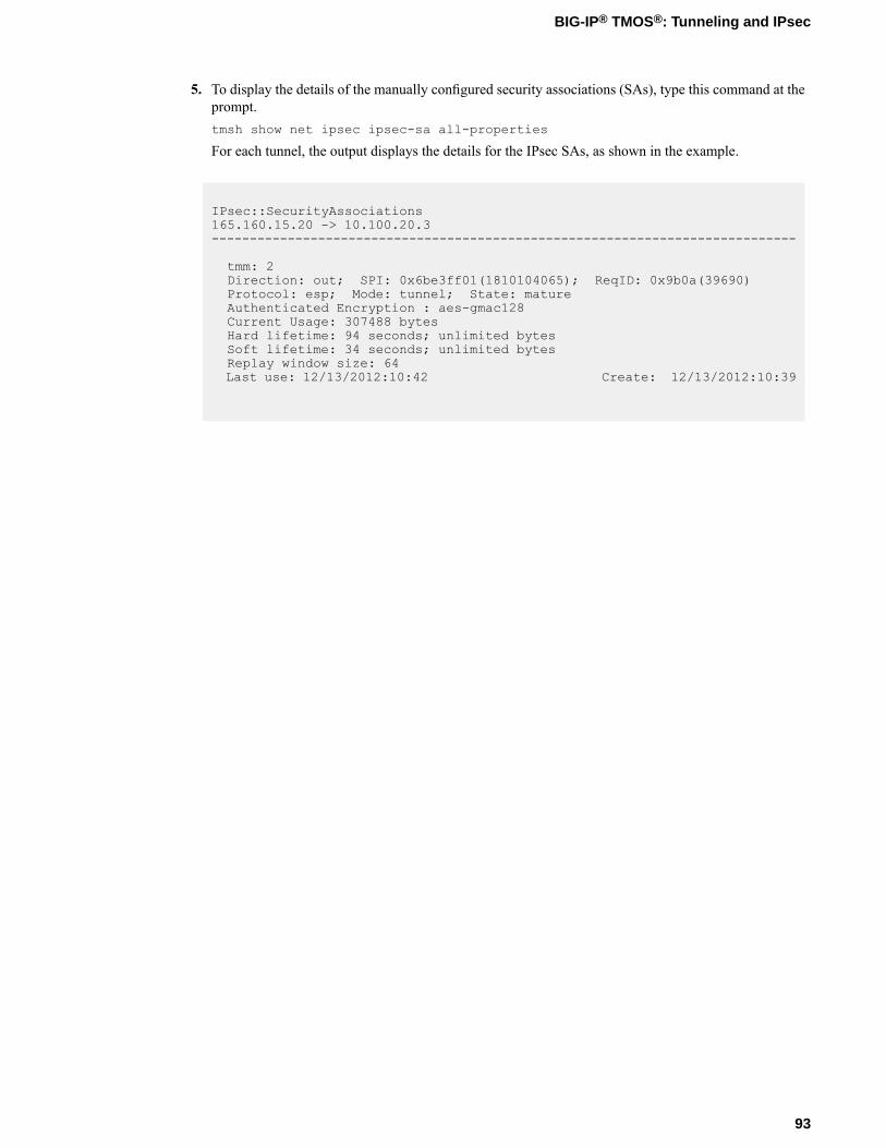
5. To display the details of the manually configured security associations (SAs), type this command at theprompt.tmsh show net ipsec ipsec-sa all-properties
For each tunnel, the output displays the details for the IPsec SAs, as shown in the example.
IPsec::SecurityAssociations165.160.15.20 -> 10.100.20.3-----------------------------------------------------------------------------
tmm: 2Direction: out; SPI: 0x6be3ff01(1810104065); ReqID: 0x9b0a(39690)Protocol: esp; Mode: tunnel; State: matureAuthenticated Encryption : aes-gmac128Current Usage: 307488 bytesHard lifetime: 94 seconds; unlimited bytesSoft lifetime: 34 seconds; unlimited bytesReplay window size: 64Last use: 12/13/2012:10:42 Create: 12/13/2012:10:39
93
BIG-IP® TMOS®: Tunneling and IPsec

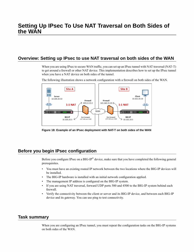
Setting Up IPsec To Use NAT Traversal on Both Sides ofthe WAN
Overview: Setting up IPsec to use NAT traversal on both sides of the WAN
When you are using IPsec to secureWAN traffic, you can set up an IPsec tunnel with NAT traversal (NAT-T)to get around a firewall or other NAT device. This implementation describes how to set up the IPsec tunnelwhen you have a NAT device on both sides of the tunnel.
The following illustration shows a network configuration with a firewall on both sides of the WAN.
Figure 18: Example of an IPsec deployment with NAT-T on both sides of the WAN
Before you begin IPsec configuration
Before you configure IPsec on a BIG-IP® device, make sure that you have completed the following generalprerequisites.
• You must have an existing routed IP network between the two locations where the BIG-IP devices willbe installed.
• The BIG-IP hardware is installed with an initial network configuration applied.• The management IP address is configured on the BIG-IP system.• If you are using NAT traversal, forward UDP ports 500 and 4500 to the BIG-IP system behind each
firewall.• Verify the connectivity between the client or server and its BIG-IP device, and between each BIG-IP
device and its gateway. You can use ping to test connectivity.
Task summary
When you are configuring an IPsec tunnel, you must repeat the configuration tasks on the BIG-IP systemson both sides of the WAN.
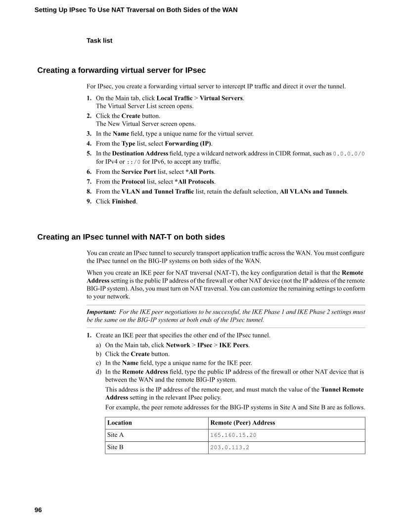
Task list
Creating a forwarding virtual server for IPsec
For IPsec, you create a forwarding virtual server to intercept IP traffic and direct it over the tunnel.
1. On the Main tab, click Local Traffic > Virtual Servers.The Virtual Server List screen opens.
2. Click the Create button.The New Virtual Server screen opens.
3. In the Name field, type a unique name for the virtual server.4. From the Type list, select Forwarding (IP).5. In theDestination Address field, type a wildcard network address in CIDR format, such as 0.0.0.0/0
for IPv4 or ::/0 for IPv6, to accept any traffic.6. From the Service Port list, select *All Ports.7. From the Protocol list, select *All Protocols.8. From the VLAN and Tunnel Traffic list, retain the default selection, All VLANs and Tunnels.9. Click Finished.
Creating an IPsec tunnel with NAT-T on both sides
You can create an IPsec tunnel to securely transport application traffic across theWAN. You must configurethe IPsec tunnel on the BIG-IP systems on both sides of the WAN.
When you create an IKE peer for NAT traversal (NAT-T), the key configuration detail is that the RemoteAddress setting is the public IP address of the firewall or other NAT device (not the IP address of the remoteBIG-IP system). Also, you must turn on NAT traversal. You can customize the remaining settings to conformto your network.
Important: For the IKE peer negotiations to be successful, the IKE Phase 1 and IKE Phase 2 settings mustbe the same on the BIG-IP systems at both ends of the IPsec tunnel.
1. Create an IKE peer that specifies the other end of the IPsec tunnel.a) On the Main tab, click Network > IPsec > IKE Peers.b) Click the Create button.c) In the Name field, type a unique name for the IKE peer.d) In the Remote Address field, type the public IP address of the firewall or other NAT device that is
between the WAN and the remote BIG-IP system.This address is the IP address of the remote peer, and must match the value of the Tunnel RemoteAddress setting in the relevant IPsec policy.For example, the peer remote addresses for the BIG-IP systems in Site A and Site B are as follows.
Remote (Peer) AddressLocation
165.160.15.20Site A
203.0.113.2Site B
96
Setting Up IPsec To Use NAT Traversal on Both Sides of the WAN
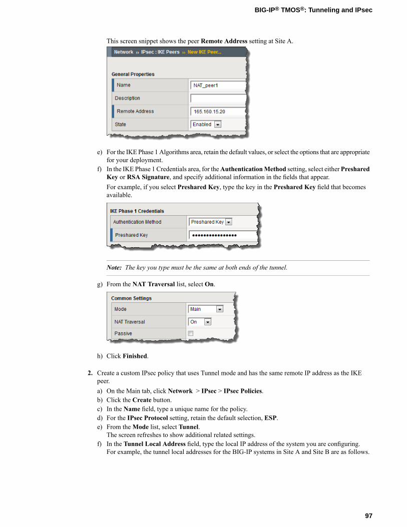
This screen snippet shows the peer Remote Address setting at Site A.
e) For the IKE Phase 1 Algorithms area, retain the default values, or select the options that are appropriatefor your deployment.
f) In the IKE Phase 1 Credentials area, for theAuthenticationMethod setting, select eitherPresharedKey or RSA Signature, and specify additional information in the fields that appear.For example, if you select Preshared Key, type the key in the Preshared Key field that becomesavailable.
Note: The key you type must be the same at both ends of the tunnel.
g) From the NAT Traversal list, select On.
h) Click Finished.
2. Create a custom IPsec policy that uses Tunnel mode and has the same remote IP address as the IKEpeer.a) On the Main tab, click Network > IPsec > IPsec Policies.b) Click the Create button.c) In the Name field, type a unique name for the policy.d) For the IPsec Protocol setting, retain the default selection, ESP.e) From theMode list, select Tunnel.
The screen refreshes to show additional related settings.f) In the Tunnel Local Address field, type the local IP address of the system you are configuring.
For example, the tunnel local addresses for the BIG-IP systems in Site A and Site B are as follows.
97
BIG-IP® TMOS®: Tunneling and IPsec
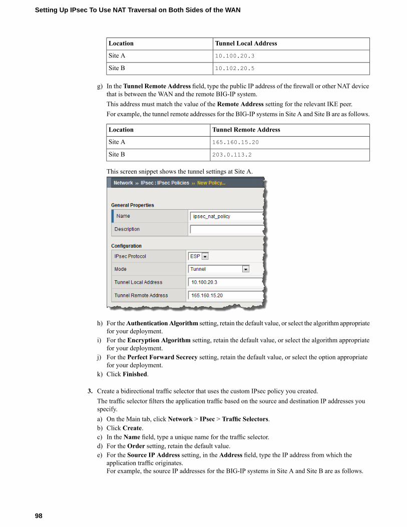
Tunnel Local AddressLocation
10.100.20.3Site A
10.102.20.5Site B
g) In the Tunnel Remote Address field, type the public IP address of the firewall or other NAT devicethat is between the WAN and the remote BIG-IP system.This address must match the value of the Remote Address setting for the relevant IKE peer.For example, the tunnel remote addresses for the BIG-IP systems in Site A and Site B are as follows.
Tunnel Remote AddressLocation
165.160.15.20Site A
203.0.113.2Site B
This screen snippet shows the tunnel settings at Site A.
h) For theAuthenticationAlgorithm setting, retain the default value, or select the algorithm appropriatefor your deployment.
i) For the Encryption Algorithm setting, retain the default value, or select the algorithm appropriatefor your deployment.
j) For the Perfect Forward Secrecy setting, retain the default value, or select the option appropriatefor your deployment.
k) Click Finished.
3. Create a bidirectional traffic selector that uses the custom IPsec policy you created.The traffic selector filters the application traffic based on the source and destination IP addresses youspecify.a) On the Main tab, click Network > IPsec > Traffic Selectors.b) Click Create.c) In the Name field, type a unique name for the traffic selector.d) For the Order setting, retain the default value.e) For the Source IP Address setting, in the Address field, type the IP address from which the
application traffic originates.For example, the source IP addresses for the BIG-IP systems in Site A and Site B are as follows.
98
Setting Up IPsec To Use NAT Traversal on Both Sides of the WAN
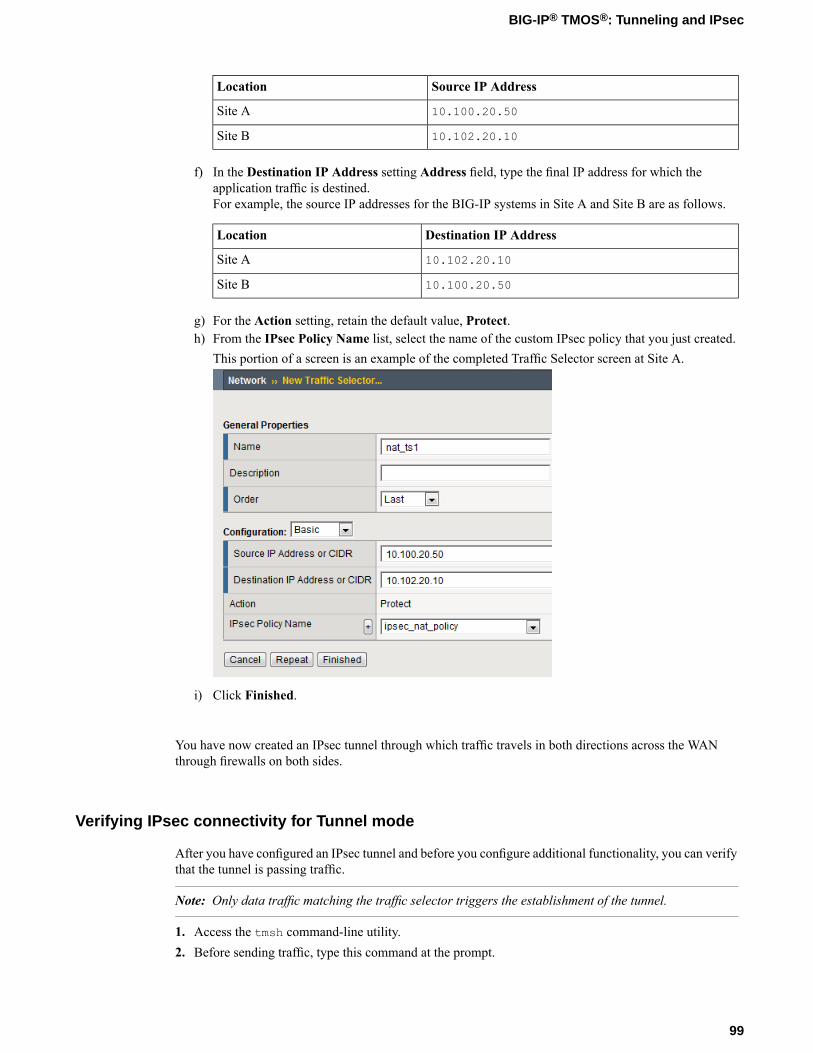
Source IP AddressLocation
10.100.20.50Site A
10.102.20.10Site B
f) In the Destination IP Address setting Address field, type the final IP address for which theapplication traffic is destined.For example, the source IP addresses for the BIG-IP systems in Site A and Site B are as follows.
Destination IP AddressLocation
10.102.20.10Site A
10.100.20.50Site B
g) For the Action setting, retain the default value, Protect.h) From the IPsec Policy Name list, select the name of the custom IPsec policy that you just created.
This portion of a screen is an example of the completed Traffic Selector screen at Site A.
i) Click Finished.
You have now created an IPsec tunnel through which traffic travels in both directions across the WANthrough firewalls on both sides.
Verifying IPsec connectivity for Tunnel mode
After you have configured an IPsec tunnel and before you configure additional functionality, you can verifythat the tunnel is passing traffic.
Note: Only data traffic matching the traffic selector triggers the establishment of the tunnel.
1. Access the tmsh command-line utility.2. Before sending traffic, type this command at the prompt.
99
BIG-IP® TMOS®: Tunneling and IPsec
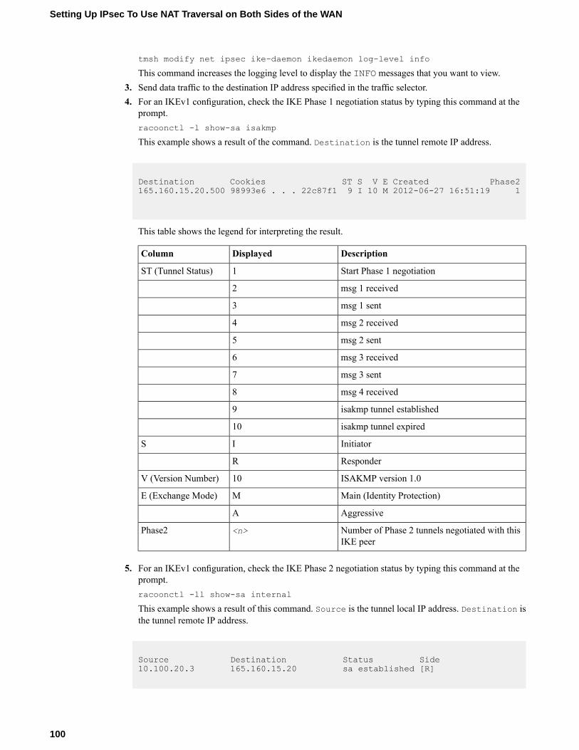
tmsh modify net ipsec ike-daemon ikedaemon log-level info
This command increases the logging level to display the INFO messages that you want to view.3. Send data traffic to the destination IP address specified in the traffic selector.4. For an IKEv1 configuration, check the IKE Phase 1 negotiation status by typing this command at the
prompt.racoonctl -l show-sa isakmp
This example shows a result of the command. Destination is the tunnel remote IP address.
Destination Cookies ST S V E Created Phase2165.160.15.20.500 98993e6 . . . 22c87f1 9 I 10 M 2012-06-27 16:51:19 1
This table shows the legend for interpreting the result.
DescriptionDisplayedColumn
Start Phase 1 negotiation1ST (Tunnel Status)
msg 1 received2
msg 1 sent3
msg 2 received4
msg 2 sent5
msg 3 received6
msg 3 sent7
msg 4 received8
isakmp tunnel established9
isakmp tunnel expired10
InitiatorIS
ResponderR
ISAKMP version 1.010V (Version Number)
Main (Identity Protection)ME (Exchange Mode)
AggressiveA
Number of Phase 2 tunnels negotiated with thisIKE peer
<n>Phase2
5. For an IKEv1 configuration, check the IKE Phase 2 negotiation status by typing this command at theprompt.racoonctl -ll show-sa internal
This example shows a result of this command. Source is the tunnel local IP address. Destination isthe tunnel remote IP address.
Source Destination Status Side10.100.20.3 165.160.15.20 sa established [R]
100
Setting Up IPsec To Use NAT Traversal on Both Sides of the WAN
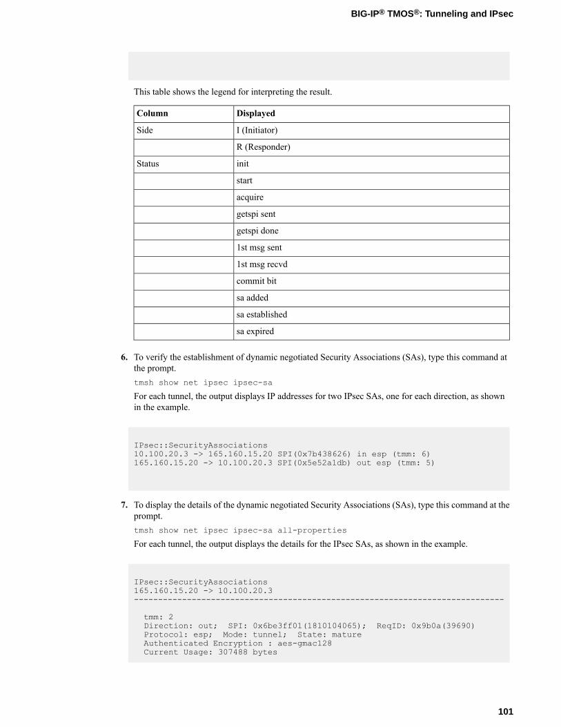
This table shows the legend for interpreting the result.
DisplayedColumn
I (Initiator)Side
R (Responder)
initStatus
start
acquire
getspi sent
getspi done
1st msg sent
1st msg recvd
commit bit
sa added
sa established
sa expired
6. To verify the establishment of dynamic negotiated Security Associations (SAs), type this command atthe prompt.tmsh show net ipsec ipsec-sa
For each tunnel, the output displays IP addresses for two IPsec SAs, one for each direction, as shownin the example.
IPsec::SecurityAssociations10.100.20.3 -> 165.160.15.20 SPI(0x7b438626) in esp (tmm: 6)165.160.15.20 -> 10.100.20.3 SPI(0x5e52a1db) out esp (tmm: 5)
7. To display the details of the dynamic negotiated Security Associations (SAs), type this command at theprompt.tmsh show net ipsec ipsec-sa all-properties
For each tunnel, the output displays the details for the IPsec SAs, as shown in the example.
IPsec::SecurityAssociations165.160.15.20 -> 10.100.20.3-----------------------------------------------------------------------------
tmm: 2Direction: out; SPI: 0x6be3ff01(1810104065); ReqID: 0x9b0a(39690)Protocol: esp; Mode: tunnel; State: matureAuthenticated Encryption : aes-gmac128Current Usage: 307488 bytes
101
BIG-IP® TMOS®: Tunneling and IPsec
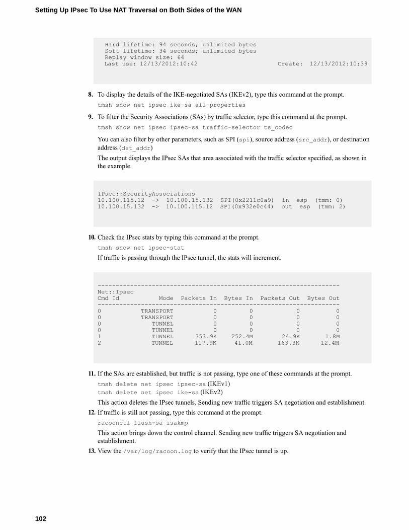
Hard lifetime: 94 seconds; unlimited bytesSoft lifetime: 34 seconds; unlimited bytesReplay window size: 64Last use: 12/13/2012:10:42 Create: 12/13/2012:10:39
8. To display the details of the IKE-negotiated SAs (IKEv2), type this command at the prompt.tmsh show net ipsec ike-sa all-properties
9. To filter the Security Associations (SAs) by traffic selector, type this command at the prompt.tmsh show net ipsec ipsec-sa traffic-selector ts_codec
You can also filter by other parameters, such as SPI (spi), source address (src_addr), or destinationaddress (dst_addr)The output displays the IPsec SAs that area associated with the traffic selector specified, as shown inthe example.
IPsec::SecurityAssociations10.100.115.12 -> 10.100.15.132 SPI(0x2211c0a9) in esp (tmm: 0)10.100.15.132 -> 10.100.115.12 SPI(0x932e0c44) out esp (tmm: 2)
10. Check the IPsec stats by typing this command at the prompt.tmsh show net ipsec-stat
If traffic is passing through the IPsec tunnel, the stats will increment.
-------------------------------------------------------------------Net::IpsecCmd Id Mode Packets In Bytes In Packets Out Bytes Out-------------------------------------------------------------------0 TRANSPORT 0 0 0 00 TRANSPORT 0 0 0 00 TUNNEL 0 0 0 00 TUNNEL 0 0 0 01 TUNNEL 353.9K 252.4M 24.9K 1.8M2 TUNNEL 117.9K 41.0M 163.3K 12.4M
11. If the SAs are established, but traffic is not passing, type one of these commands at the prompt.tmsh delete net ipsec ipsec-sa (IKEv1)tmsh delete net ipsec ike-sa (IKEv2)This action deletes the IPsec tunnels. Sending new traffic triggers SA negotiation and establishment.
12. If traffic is still not passing, type this command at the prompt.racoonctl flush-sa isakmp
This action brings down the control channel. Sending new traffic triggers SA negotiation andestablishment.
13. View the /var/log/racoon.log to verify that the IPsec tunnel is up.
102
Setting Up IPsec To Use NAT Traversal on Both Sides of the WAN
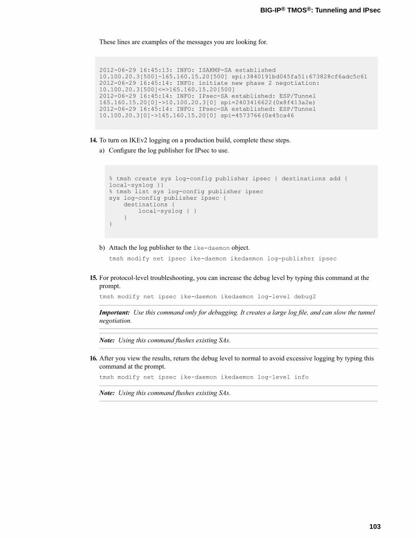
These lines are examples of the messages you are looking for.
2012-06-29 16:45:13: INFO: ISAKMP-SA established10.100.20.3[500]-165.160.15.20[500] spi:3840191bd045fa51:673828cf6adc5c612012-06-29 16:45:14: INFO: initiate new phase 2 negotiation:10.100.20.3[500]<=>165.160.15.20[500]2012-06-29 16:45:14: INFO: IPsec-SA established: ESP/Tunnel165.160.15.20[0]->10.100.20.3[0] spi=2403416622(0x8f413a2e)2012-06-29 16:45:14: INFO: IPsec-SA established: ESP/Tunnel10.100.20.3[0]->165.160.15.20[0] spi=4573766(0x45ca46
14. To turn on IKEv2 logging on a production build, complete these steps.a) Configure the log publisher for IPsec to use.
% tmsh create sys log-config publisher ipsec { destinations add {local-syslog }}% tmsh list sys log-config publisher ipsecsys log-config publisher ipsec {
destinations {local-syslog { }
}}
b) Attach the log publisher to the ike-daemon object.tmsh modify net ipsec ike-daemon ikedaemon log-publisher ipsec
15. For protocol-level troubleshooting, you can increase the debug level by typing this command at theprompt.tmsh modify net ipsec ike-daemon ikedaemon log-level debug2
Important: Use this command only for debugging. It creates a large log file, and can slow the tunnelnegotiation.
Note: Using this command flushes existing SAs.
16. After you view the results, return the debug level to normal to avoid excessive logging by typing thiscommand at the prompt.tmsh modify net ipsec ike-daemon ikedaemon log-level info
Note: Using this command flushes existing SAs.
103
BIG-IP® TMOS®: Tunneling and IPsec

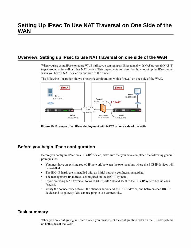
Setting Up IPsec To Use NAT Traversal on One Side of theWAN
Overview: Setting up IPsec to use NAT traversal on one side of the WAN
When you are using IPsec to secureWAN traffic, you can set up an IPsec tunnel with NAT traversal (NAT-T)to get around a firewall or other NAT device. This implementation describes how to set up the IPsec tunnelwhen you have a NAT device on one side of the tunnel.
The following illustration shows a network configuration with a firewall on one side of the WAN.
Figure 19: Example of an IPsec deployment with NAT-T on one side of the WAN
Before you begin IPsec configuration
Before you configure IPsec on a BIG-IP® device, make sure that you have completed the following generalprerequisites.
• You must have an existing routed IP network between the two locations where the BIG-IP devices willbe installed.
• The BIG-IP hardware is installed with an initial network configuration applied.• The management IP address is configured on the BIG-IP system.• If you are using NAT traversal, forward UDP ports 500 and 4500 to the BIG-IP system behind each
firewall.• Verify the connectivity between the client or server and its BIG-IP device, and between each BIG-IP
device and its gateway. You can use ping to test connectivity.
Task summary
When you are configuring an IPsec tunnel, you must repeat the configuration tasks on the BIG-IP systemson both sides of the WAN.
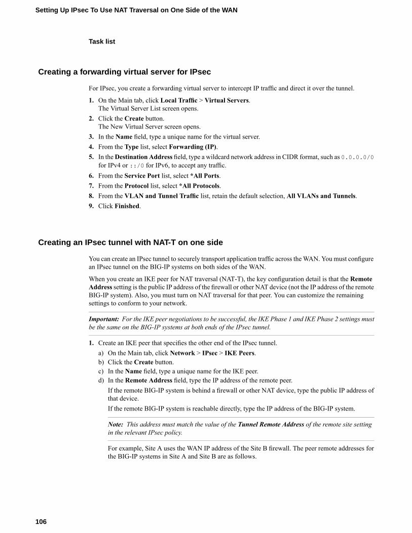
Task list
Creating a forwarding virtual server for IPsec
For IPsec, you create a forwarding virtual server to intercept IP traffic and direct it over the tunnel.
1. On the Main tab, click Local Traffic > Virtual Servers.The Virtual Server List screen opens.
2. Click the Create button.The New Virtual Server screen opens.
3. In the Name field, type a unique name for the virtual server.4. From the Type list, select Forwarding (IP).5. In theDestination Address field, type a wildcard network address in CIDR format, such as 0.0.0.0/0
for IPv4 or ::/0 for IPv6, to accept any traffic.6. From the Service Port list, select *All Ports.7. From the Protocol list, select *All Protocols.8. From the VLAN and Tunnel Traffic list, retain the default selection, All VLANs and Tunnels.9. Click Finished.
Creating an IPsec tunnel with NAT-T on one side
You can create an IPsec tunnel to securely transport application traffic across theWAN. You must configurean IPsec tunnel on the BIG-IP systems on both sides of the WAN.
When you create an IKE peer for NAT traversal (NAT-T), the key configuration detail is that the RemoteAddress setting is the public IP address of the firewall or other NAT device (not the IP address of the remoteBIG-IP system). Also, you must turn on NAT traversal for that peer. You can customize the remainingsettings to conform to your network.
Important: For the IKE peer negotiations to be successful, the IKE Phase 1 and IKE Phase 2 settings mustbe the same on the BIG-IP systems at both ends of the IPsec tunnel.
1. Create an IKE peer that specifies the other end of the IPsec tunnel.a) On the Main tab, click Network > IPsec > IKE Peers.b) Click the Create button.c) In the Name field, type a unique name for the IKE peer.d) In the Remote Address field, type the IP address of the remote peer.
If the remote BIG-IP system is behind a firewall or other NAT device, type the public IP address ofthat device.If the remote BIG-IP system is reachable directly, type the IP address of the BIG-IP system.
Note: This address must match the value of the Tunnel Remote Address of the remote site settingin the relevant IPsec policy.
For example, Site A uses the WAN IP address of the Site B firewall. The peer remote addresses forthe BIG-IP systems in Site A and Site B are as follows.
106
Setting Up IPsec To Use NAT Traversal on One Side of the WAN
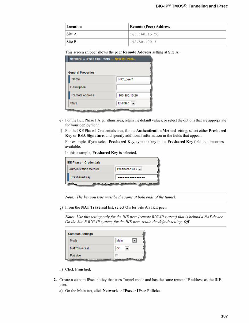
Remote (Peer) AddressLocation
165.160.15.20Site A
198.50.100.3Site B
This screen snippet shows the peer Remote Address setting at Site A.
e) For the IKE Phase 1 Algorithms area, retain the default values, or select the options that are appropriatefor your deployment.
f) For the IKE Phase 1 Credentials area, for theAuthenticationMethod setting, select eitherPresharedKey or RSA Signature, and specify additional information in the fields that appear.For example, if you select Preshared Key, type the key in the Preshared Key field that becomesavailable.In this example, Preshared Key is selected.
Note: The key you type must be the same at both ends of the tunnel.
g) From the NAT Traversal list, select On for Site A's IKE peer.
Note: Use this setting only for the IKE peer (remote BIG-IP system) that is behind a NAT device.On the Site B BIG-IP system, for the IKE peer, retain the default setting, Off.
h) Click Finished.
2. Create a custom IPsec policy that uses Tunnel mode and has the same remote IP address as the IKEpeer.a) On the Main tab, click Network > IPsec > IPsec Policies.
107
BIG-IP® TMOS®: Tunneling and IPsec
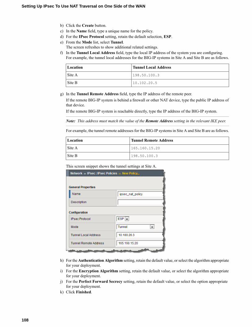
b) Click the Create button.c) In the Name field, type a unique name for the policy.d) For the IPsec Protocol setting, retain the default selection, ESP.e) From theMode list, select Tunnel.
The screen refreshes to show additional related settings.f) In the Tunnel Local Address field, type the local IP address of the system you are configuring.
For example, the tunnel local addresses for the BIG-IP systems in Site A and Site B are as follows.
Tunnel Local AddressLocation
198.50.100.3Site A
10.102.20.5Site B
g) In the Tunnel Remote Address field, type the IP address of the remote peer.If the remote BIG-IP system is behind a firewall or other NAT device, type the public IP address ofthat device.If the remote BIG-IP system is reachable directly, type the IP address of the BIG-IP system.
Note: This address must match the value of the Remote Address setting in the relevant IKE peer.
For example, the tunnel remote addresses for the BIG-IP systems in Site A and Site B are as follows.
Tunnel Remote AddressLocation
165.160.15.20Site A
198.50.100.3Site B
This screen snippet shows the tunnel settings at Site A.
h) For theAuthenticationAlgorithm setting, retain the default value, or select the algorithm appropriatefor your deployment.
i) For the Encryption Algorithm setting, retain the default value, or select the algorithm appropriatefor your deployment.
j) For the Perfect Forward Secrecy setting, retain the default value, or select the option appropriatefor your deployment.
k) Click Finished.
108
Setting Up IPsec To Use NAT Traversal on One Side of the WAN
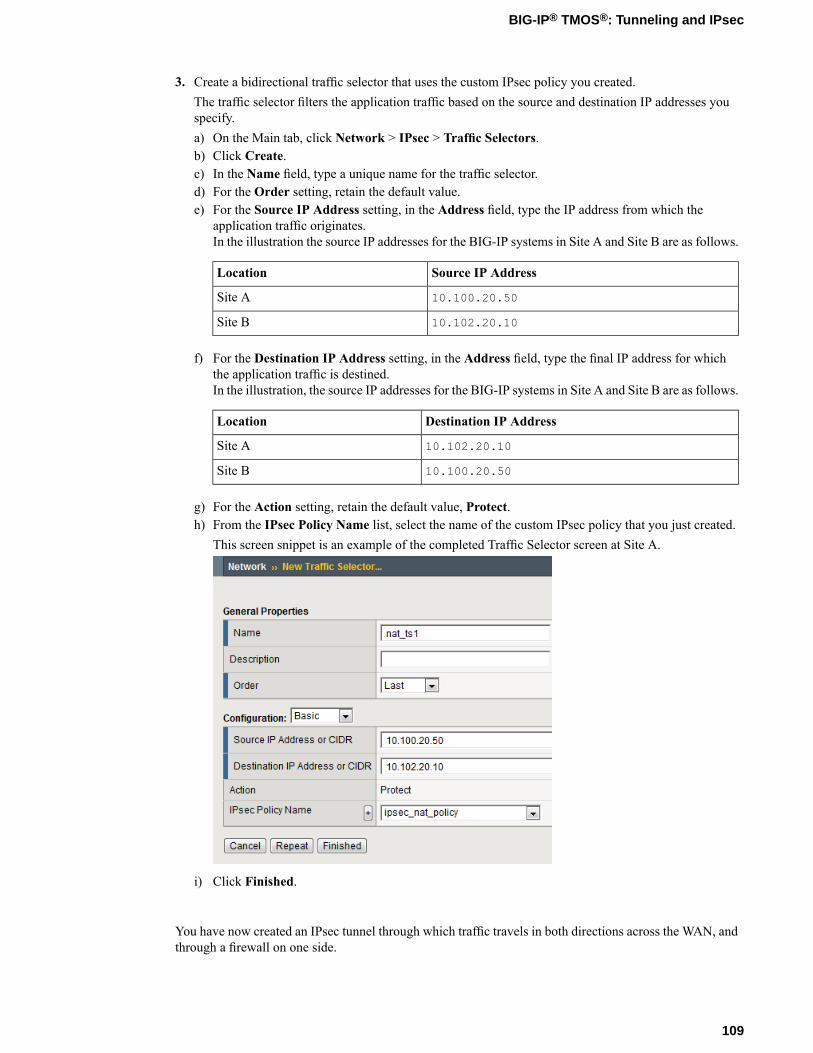
3. Create a bidirectional traffic selector that uses the custom IPsec policy you created.The traffic selector filters the application traffic based on the source and destination IP addresses youspecify.a) On the Main tab, click Network > IPsec > Traffic Selectors.b) Click Create.c) In the Name field, type a unique name for the traffic selector.d) For the Order setting, retain the default value.e) For the Source IP Address setting, in the Address field, type the IP address from which the
application traffic originates.In the illustration the source IP addresses for the BIG-IP systems in Site A and Site B are as follows.
Source IP AddressLocation
10.100.20.50Site A
10.102.20.10Site B
f) For the Destination IP Address setting, in the Address field, type the final IP address for whichthe application traffic is destined.In the illustration, the source IP addresses for the BIG-IP systems in Site A and Site B are as follows.
Destination IP AddressLocation
10.102.20.10Site A
10.100.20.50Site B
g) For the Action setting, retain the default value, Protect.h) From the IPsec Policy Name list, select the name of the custom IPsec policy that you just created.
This screen snippet is an example of the completed Traffic Selector screen at Site A.
i) Click Finished.
You have now created an IPsec tunnel through which traffic travels in both directions across the WAN, andthrough a firewall on one side.
109
BIG-IP® TMOS®: Tunneling and IPsec
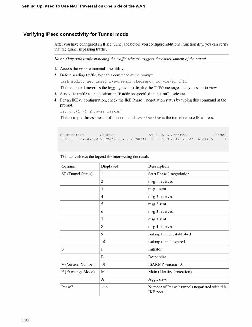
Verifying IPsec connectivity for Tunnel mode
After you have configured an IPsec tunnel and before you configure additional functionality, you can verifythat the tunnel is passing traffic.
Note: Only data traffic matching the traffic selector triggers the establishment of the tunnel.
1. Access the tmsh command-line utility.2. Before sending traffic, type this command at the prompt.
tmsh modify net ipsec ike-daemon ikedaemon log-level info
This command increases the logging level to display the INFO messages that you want to view.3. Send data traffic to the destination IP address specified in the traffic selector.4. For an IKEv1 configuration, check the IKE Phase 1 negotiation status by typing this command at the
prompt.racoonctl -l show-sa isakmp
This example shows a result of the command. Destination is the tunnel remote IP address.
Destination Cookies ST S V E Created Phase2165.160.15.20.500 98993e6 . . . 22c87f1 9 I 10 M 2012-06-27 16:51:19 1
This table shows the legend for interpreting the result.
DescriptionDisplayedColumn
Start Phase 1 negotiation1ST (Tunnel Status)
msg 1 received2
msg 1 sent3
msg 2 received4
msg 2 sent5
msg 3 received6
msg 3 sent7
msg 4 received8
isakmp tunnel established9
isakmp tunnel expired10
InitiatorIS
ResponderR
ISAKMP version 1.010V (Version Number)
Main (Identity Protection)ME (Exchange Mode)
AggressiveA
Number of Phase 2 tunnels negotiated with thisIKE peer
<n>Phase2
110
Setting Up IPsec To Use NAT Traversal on One Side of the WAN
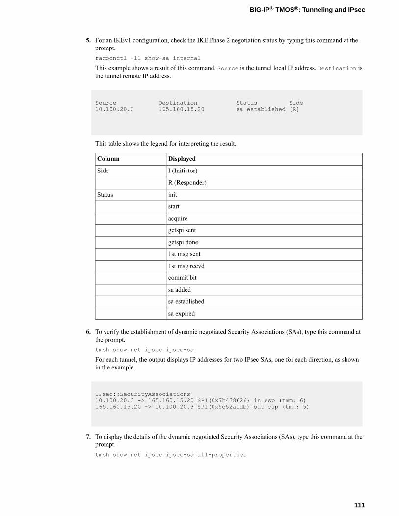
5. For an IKEv1 configuration, check the IKE Phase 2 negotiation status by typing this command at theprompt.racoonctl -ll show-sa internal
This example shows a result of this command. Source is the tunnel local IP address. Destination isthe tunnel remote IP address.
Source Destination Status Side10.100.20.3 165.160.15.20 sa established [R]
This table shows the legend for interpreting the result.
DisplayedColumn
I (Initiator)Side
R (Responder)
initStatus
start
acquire
getspi sent
getspi done
1st msg sent
1st msg recvd
commit bit
sa added
sa established
sa expired
6. To verify the establishment of dynamic negotiated Security Associations (SAs), type this command atthe prompt.tmsh show net ipsec ipsec-sa
For each tunnel, the output displays IP addresses for two IPsec SAs, one for each direction, as shownin the example.
IPsec::SecurityAssociations10.100.20.3 -> 165.160.15.20 SPI(0x7b438626) in esp (tmm: 6)165.160.15.20 -> 10.100.20.3 SPI(0x5e52a1db) out esp (tmm: 5)
7. To display the details of the dynamic negotiated Security Associations (SAs), type this command at theprompt.tmsh show net ipsec ipsec-sa all-properties
111
BIG-IP® TMOS®: Tunneling and IPsec
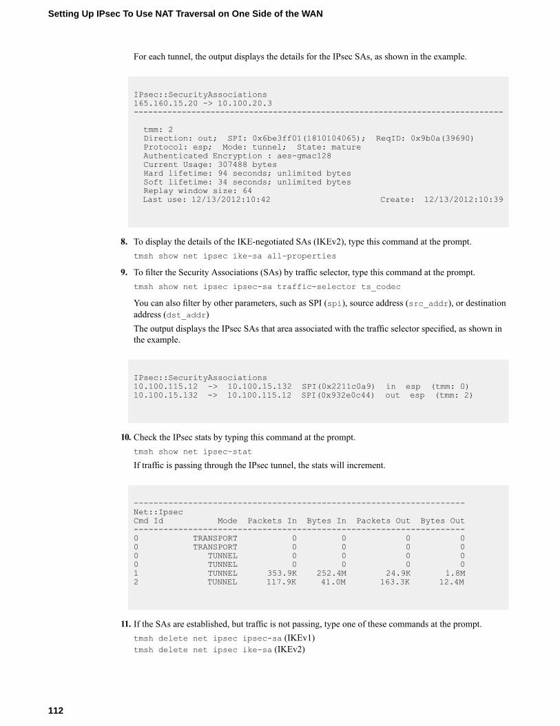
For each tunnel, the output displays the details for the IPsec SAs, as shown in the example.
IPsec::SecurityAssociations165.160.15.20 -> 10.100.20.3-----------------------------------------------------------------------------
tmm: 2Direction: out; SPI: 0x6be3ff01(1810104065); ReqID: 0x9b0a(39690)Protocol: esp; Mode: tunnel; State: matureAuthenticated Encryption : aes-gmac128Current Usage: 307488 bytesHard lifetime: 94 seconds; unlimited bytesSoft lifetime: 34 seconds; unlimited bytesReplay window size: 64Last use: 12/13/2012:10:42 Create: 12/13/2012:10:39
8. To display the details of the IKE-negotiated SAs (IKEv2), type this command at the prompt.tmsh show net ipsec ike-sa all-properties
9. To filter the Security Associations (SAs) by traffic selector, type this command at the prompt.tmsh show net ipsec ipsec-sa traffic-selector ts_codec
You can also filter by other parameters, such as SPI (spi), source address (src_addr), or destinationaddress (dst_addr)The output displays the IPsec SAs that area associated with the traffic selector specified, as shown inthe example.
IPsec::SecurityAssociations10.100.115.12 -> 10.100.15.132 SPI(0x2211c0a9) in esp (tmm: 0)10.100.15.132 -> 10.100.115.12 SPI(0x932e0c44) out esp (tmm: 2)
10. Check the IPsec stats by typing this command at the prompt.tmsh show net ipsec-stat
If traffic is passing through the IPsec tunnel, the stats will increment.
-------------------------------------------------------------------Net::IpsecCmd Id Mode Packets In Bytes In Packets Out Bytes Out-------------------------------------------------------------------0 TRANSPORT 0 0 0 00 TRANSPORT 0 0 0 00 TUNNEL 0 0 0 00 TUNNEL 0 0 0 01 TUNNEL 353.9K 252.4M 24.9K 1.8M2 TUNNEL 117.9K 41.0M 163.3K 12.4M
11. If the SAs are established, but traffic is not passing, type one of these commands at the prompt.tmsh delete net ipsec ipsec-sa (IKEv1)tmsh delete net ipsec ike-sa (IKEv2)
112
Setting Up IPsec To Use NAT Traversal on One Side of the WAN
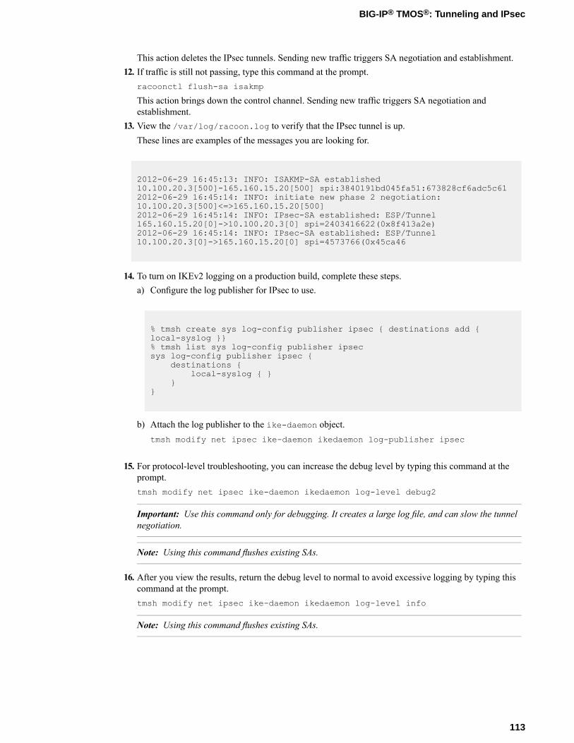
This action deletes the IPsec tunnels. Sending new traffic triggers SA negotiation and establishment.12. If traffic is still not passing, type this command at the prompt.
racoonctl flush-sa isakmp
This action brings down the control channel. Sending new traffic triggers SA negotiation andestablishment.
13. View the /var/log/racoon.log to verify that the IPsec tunnel is up.These lines are examples of the messages you are looking for.
2012-06-29 16:45:13: INFO: ISAKMP-SA established10.100.20.3[500]-165.160.15.20[500] spi:3840191bd045fa51:673828cf6adc5c612012-06-29 16:45:14: INFO: initiate new phase 2 negotiation:10.100.20.3[500]<=>165.160.15.20[500]2012-06-29 16:45:14: INFO: IPsec-SA established: ESP/Tunnel165.160.15.20[0]->10.100.20.3[0] spi=2403416622(0x8f413a2e)2012-06-29 16:45:14: INFO: IPsec-SA established: ESP/Tunnel10.100.20.3[0]->165.160.15.20[0] spi=4573766(0x45ca46
14. To turn on IKEv2 logging on a production build, complete these steps.a) Configure the log publisher for IPsec to use.
% tmsh create sys log-config publisher ipsec { destinations add {local-syslog }}% tmsh list sys log-config publisher ipsecsys log-config publisher ipsec {
destinations {local-syslog { }
}}
b) Attach the log publisher to the ike-daemon object.tmsh modify net ipsec ike-daemon ikedaemon log-publisher ipsec
15. For protocol-level troubleshooting, you can increase the debug level by typing this command at theprompt.tmsh modify net ipsec ike-daemon ikedaemon log-level debug2
Important: Use this command only for debugging. It creates a large log file, and can slow the tunnelnegotiation.
Note: Using this command flushes existing SAs.
16. After you view the results, return the debug level to normal to avoid excessive logging by typing thiscommand at the prompt.tmsh modify net ipsec ike-daemon ikedaemon log-level info
Note: Using this command flushes existing SAs.
113
BIG-IP® TMOS®: Tunneling and IPsec

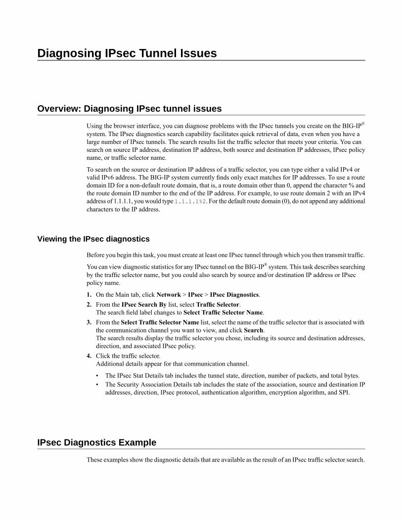
Diagnosing IPsec Tunnel Issues
Overview: Diagnosing IPsec tunnel issues
Using the browser interface, you can diagnose problems with the IPsec tunnels you create on the BIG-IP®
system. The IPsec diagnostics search capability facilitates quick retrieval of data, even when you have alarge number of IPsec tunnels. The search results list the traffic selector that meets your criteria. You cansearch on source IP address, destination IP address, both source and destination IP addresses, IPsec policyname, or traffic selector name.
To search on the source or destination IP address of a traffic selector, you can type either a valid IPv4 orvalid IPv6 address. The BIG-IP system currently finds only exact matches for IP addresses. To use a routedomain ID for a non-default route domain, that is, a route domain other than 0, append the character % andthe route domain ID number to the end of the IP address. For example, to use route domain 2 with an IPv4address of 1.1.1.1, youwould type 1.1.1.1%2. For the default route domain (0), do not append any additionalcharacters to the IP address.
Viewing the IPsec diagnostics
Before you begin this task, you must create at least one IPsec tunnel through which you then transmit traffic.
You can view diagnostic statistics for any IPsec tunnel on the BIG-IP® system. This task describes searchingby the traffic selector name, but you could also search by source and/or destination IP address or IPsecpolicy name.
1. On the Main tab, click Network > IPsec > IPsec Diagnostics.2. From the IPsec Search By list, select Traffic Selector.
The search field label changes to Select Traffic Selector Name.3. From the Select Traffic Selector Name list, select the name of the traffic selector that is associated with
the communication channel you want to view, and click Search.The search results display the traffic selector you chose, including its source and destination addresses,direction, and associated IPsec policy.
4. Click the traffic selector.Additional details appear for that communication channel.
• The IPsec Stat Details tab includes the tunnel state, direction, number of packets, and total bytes.• The Security Association Details tab includes the state of the association, source and destination IP
addresses, direction, IPsec protocol, authentication algorithm, encryption algorithm, and SPI.
IPsec Diagnostics Example
These examples show the diagnostic details that are available as the result of an IPsec traffic selector search.
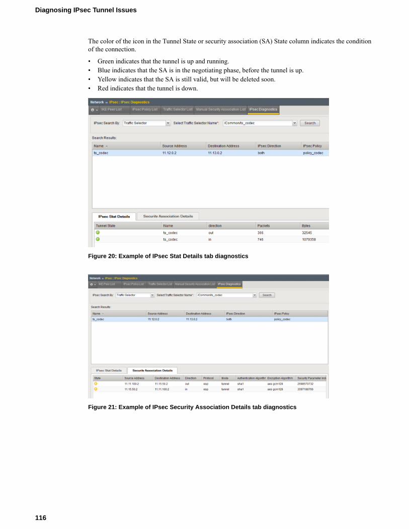
The color of the icon in the Tunnel State or security association (SA) State column indicates the conditionof the connection.
• Green indicates that the tunnel is up and running.• Blue indicates that the SA is in the negotiating phase, before the tunnel is up.• Yellow indicates that the SA is still valid, but will be deleted soon.• Red indicates that the tunnel is down.
Figure 20: Example of IPsec Stat Details tab diagnostics
Figure 21: Example of IPsec Security Association Details tab diagnostics
116
Diagnosing IPsec Tunnel Issues
Legal Notices
Legal notices
Publication Date
This document was published on May 9, 2016.
Publication Number
MAN-0537-02
Copyright
Copyright © 2012-2016, F5 Networks, Inc. All rights reserved.
F5 Networks, Inc. (F5) believes the information it furnishes to be accurate and reliable. However, F5 assumesno responsibility for the use of this information, nor any infringement of patents or other rights of thirdparties which may result from its use. No license is granted by implication or otherwise under any patent,copyright, or other intellectual property right of F5 except as specifically described by applicable userlicenses. F5 reserves the right to change specifications at any time without notice.
Trademarks
Trademarks
For a current list of F5 trademarks and service marks, seehttp://www.f5.com/about/guidelines-policies/trademarks/.
All other product and company names herein may be trademarks of their respective owners.
Patents
This product may be protected by one or more patents indicated at:http://www.f5.com/about/guidelines-policies/patents
Export Regulation Notice
This product may include cryptographic software. Under the Export Administration Act, the United Statesgovernment may consider it a criminal offense to export this product from the United States.
RF Interference Warning
This is a Class A product. In a domestic environment this product may cause radio interference, in whichcase the user may be required to take adequate measures.
FCC Compliance
This equipment has been tested and found to comply with the limits for a Class A digital device pursuantto Part 15 of FCC rules. These limits are designed to provide reasonable protection against harmfulinterference when the equipment is operated in a commercial environment. This unit generates, uses, andcan radiate radio frequency energy and, if not installed and used in accordance with the instruction manual,
may cause harmful interference to radio communications. Operation of this equipment in a residential areais likely to cause harmful interference, in which case the user, at his own expense, will be required to takewhatever measures may be required to correct the interference.
Anymodifications to this device, unless expressly approved by themanufacturer, can void the user's authorityto operate this equipment under part 15 of the FCC rules.
Canadian Regulatory Compliance
This Class A digital apparatus complies with Canadian ICES-003.
Standards Compliance
This product conforms to the IEC, European Union, ANSI/UL and Canadian CSA standards applicable toInformation Technology products at the time of manufacture.
118
Legal Notices
Index
A
ARP entriespopulating manually for virtual network segments 17
authentication algorithmsnegotiating 47, 59, 75
B
BIG-IP monitor type 39
C
certificates, See x509 certificates.cloud
about connectivity in 13config sync
about behavior with NVGRE tunnels in HA pair 30disabling for tunnels 25
configuration synchronizationsyncing to group 40
connectionsand VM migration 35dropping 40, 45preserving 36
custom IPsec policies 70
D
DAG tunnelspecifying a port number 23
default IPsec policies 49, 63, 70destination IP addresses
for traffic selectors 45, 50, 63, 70, 80, 91, 96, 106diagnostics
example for IPsec tunnel 115for IPsec tunnels 115
E
encapsulationcreating tunnels for 8, 10
encryption algorithmsnegotiating 47, 59, 75
encryption contents 47, 76, 88EtherIP configuration results 40, 45EtherIP profile type
and self IP addresses 37, 42purpose of 37, 42
EtherIP protocol 35EtherIP tunneling 36EtherIP tunnels
and IPsec 41and self IP addresses 37, 42defined 35purpose of 37, 42
F
FDB entriespopulating manually for virtual network segments 17
forwarding virtual serverscreating for IPsec 49, 61, 70, 77, 88, 96, 106
H
high availabilityand tunnels 25and VXLAN 24
HNV routing domainconfiguring per-subnet tunnels for 33
Hyper-Vabout NVGRE tunnel representation for 30
I
IKE (Internet Key Exchange)defined 47, 59, 75
IKE peersdefined 48, 60, 76for data exchange 47, 59, 75
IKE Phase 1configuring 52, 61, 77
interfacestagging 36, 41
Internet Key Exchange, See IKE (Internet Key Exchange)IPComp
about 48, 60IP header encryption 47, 59, 76, 88IPsec configuration result 57, 68, 85IPsec configurations
prerequisites for 95, 105IPsec diagnostics
examples of statistics displayed 115IPsec IKE peers
creating 52, 61, 77creating for NAT-T 96, 106
IPsec interface tunnelcreating 71overview 69
IPsec policiescreating 49, 63, 70, 79, 89creating for EtherIP traffic 44creating for NAT-T 96, 106defined 48, 60, 76
IPsec profilescustomizing 71
IPsec protocolabout diagnostics for 115and EtherIP tunnels 41and prerequisites for configuring 69diagnosing tunnel issues 115prerequisites for configuring 48, 60, 76, 88purpose of 48, 60, 76, 88
119
Index

IPsec protocol suitecomponents of 48, 60, 76described 47, 59, 75, 87
IPsec security associationscreating manually 90
IPsec traffic selectorscreating 50, 63, 70, 80creating for EtherIP traffic 45creating for manually keyed security associations 91creating for NAT-T 96, 106defined 48, 60, 76viewing diagnostics for 115
IPsec Transport mode, See Transport modeIPsec tunnel
creating for NAT-T 96, 106verifying connectivity 53, 81, 92, 99, 110
IPsec Tunnel mode, See Tunnel modeIP tunneling
about 7about transparent 11creating point-to-point 8creating transparent 11
ISAKMP-SA security association 47, 59, 75iSession
and IPsec with NAT-T 95, 105
L
L2 location recordspopulating manually 17
live migrationand existing connections 36of virtual machines 35
local pool membersload balancing to 35
M
MAC addressesadding to virtual network forwarding table 17removing from virtual network forwarding table 17
MAC framesand tunneling 35
manual security associationscreating IPsec policies for 89
monitorsfor EtherIP tunneling 39
N
NAT traversaland IPsec 105using IPsec 95, 105
negotiationof security associations 47, 59, 75
network virtualizationabout tunneling types for 16centralized vs. decentralized model 15configuring BIG-IP system as gateway 13creating tunnels for 14
network virtualization tunnelsconsiderations for configuring 17
NVGREabout configuration in an HA pair 30about configuring for HA pair 29about tunnel representation for Hyper-V 30about using BIG-IP system as gateway for 33configuration example using tmsh 19configuring for BIG-IP system as gateway 33configuring tunnel for HA pair 30defined 15
O
overlay networksabout using NVGRE for 30and VXLAN-GPE tunnels 26and VXLAN tunnels 23bridging traffic to physical network 24using VXLAN 21
OVSDB management componentabout configuring VXLAN tunnels with 25setting up 25
P
packet encryption 47, 76, 88payload encryption 47, 59, 76, 88Phase 1 negotiation
and IKE protocol 47, 59, 75, 87defined 47, 59, 75
Phase 2 negotiationdefined 47, 59, 75
point-to-point tunnelsabout 7creating 8example 9
policiesdefined for IPsec 48, 60, 76
pool membersas virtual machines 35
prerequisitesfor configuring IPsec 95, 105
profilescustomizing for IPsec tunnel interface 71for EtherIP tunneling 37, 42
R
remote pool membersload balancing to 35
routesand tunnels 9
S
SAs (security associations)creating IPsec policies for 89creating manually 90
secure channelsabout establishing 87establishing 47, 59, 69, 75, 95, 105
120
Index

security associationscreating IPsec policies for 89creating manually 90negotiating 47, 59, 75
self IP addressesand VLAN groups 38, 44and VLANs 38, 43creating 38, 43creating for IP tunnels 8, 72creating for IPv4 VLAN group 38, 44
source portsand traffic selectors 50, 63, 80, 91
SSL protocolalternative to 47, 59, 69, 75, 87
T
traffic groupsand tunnels 12
traffic selectorsSee also IPsec traffic selectors
creating 50, 63, 70, 80creating for EtherIP traffic 45creating for manually keyed security associations 91defined 48, 60, 76See also IPsec traffic selectors
Transparent Ethernet Bridgingdescribed 15
transparent tunnelsabout 11creating 11
Transport modesecurity implications of 59verifying connectivity 64
Tunnel modedefined 47, 76, 88verifying connectivity 53, 81, 92, 99, 110
tunnel protocolslisting supported 7
tunnelsabout 7about BIG-IP to multiple devices 10about configuring for VXLAN-GPE 26about point-to-point 7about static configuration for network virtualization 17about transparent 11about types used for network virtualization 16adding routes for 9and config sync behavior 12and HA configurations 12and self IP addresses 8, 72and traffic group setting 12configuring for network virtualization 13–14configuring inbound-only for NVGRE gateway 33configuring per subnet for HNV routing domain 33creating between BIG-IP and unknown device 10creating for VXLAN 23creating for VXLAN-GPE 26creating IPsec interface type 71creating point-to-point 8creating transparent 11example of diagnostics for IPsec 115
tunnels (continued)example of point-to-point 9specifying IPsec traffic selector 71viewing statistics for 21
V
Virtual eXtended LAN, See VXLANvirtualized networks
about tunneling types for 16configuring BIG-IP system as gateway for 13configuring on BIG-IP system 14terminology defined 14
Virtual Location monitorscreating 39defined 35, 39
virtual machinesand pool members 35migrating 36
virtual serversSee also forwarding virtual servers
listening on VXLAN VNI command example 21See also forwarding virtual servers
VLAN groupsand self IP addresses 38, 44creating for EtherIP tunnels 37, 42creating for VXLAN 24
VLANsand self IP addresses 38, 43creating 36, 41modifying for DAG tunnel 23tagged interfaces for 36, 41
VMware vMotion 35VTEP entries
adding to virtual network forwarding table 17VXLAN
about 21about configuring BIG-IP system as gateway 21adding virtual server command example 21and high availability 24bridging with L2 VLAN network 21configuration example using tmsh 20considerations for configuring 22creating tunnels for 23creating VLAN groups for 24multicast mode defined 15pre-requisites for configuring 22terminology defined 14unicast mode defined 15
VXLAN-GPEcreating tunnels for 26
VXLAN-GPE tunnelsabout configuring 26
VXLAN headerabout adding fields 26
W
WAN traversalabout using IPsec 87using IPsec 47, 59, 69, 75
121
Index

wide area networksand live migration 35
X
x509 certificatesand IKE peers 52, 61, 77
122
Index


![MAG Service Configuration Mode Commands...Enteringtheabovecommandsequenceresultsinthefollowingprompt: [context_name]host_name(config-mag-service)# SyntaxDescription encapsulation{gre|ipip](https://img.pdfslide.us/doc/110x75/5fa64aa99b6e755f16468b28/mag-service-configuration-mode-commands-enteringtheabovecommandsequenceresultsinthefollowingprompt.jpg)