Embed Size (px)
Citation preview
P e r g a m o n 0306-4549(93)E0007-M
Ann. Nucl. Energy, Vol. 21, No. 9, pp. 541-562, 1994 1994 Elsevier Science Ltd Printed in Great Britain
A FOUR-REGION, MOVING-BOUNDARY MODEL OF A ONCE-THROUGH, HELICAL-COIL STEAM GENERATOR~"
M. A. ABDALLA
Oak Ridge Associated Universities, P.O. Box 117, Oak Ridge, TN 37831-0117, U.S.A.
(Received 6 October 1993)
Abstract--A dynamic model of a once-through, helical-coil steam generator is presented. The model simulates the advanced liquid metal reactor superheated cycle steam generator with a four-region, moving- boundary, draft-flux flow model. The model is described by a set of nonlinear differential equations derived from the fundamental equations of conservation of mass, energy, and momentum. Sample results of steady-state and transient calculations are presented.
I. INTRODUCTION
Steam generators in a nuclear power plant provide cooling of the reactor and produce steam to drive the turbine. Characterizations of the thermal-hydraulic transients of the steam generator are essential in the study of the overall nuclear power plant performance as well as for the design of its appropriate control systems. The prediction of the steam generator behavior under load transients requires the use of nonlinear dynamic models of the steam generator.
The steam generator model presented in this paper consists of subcooled, nucleate boiling, film boiling, and superheated regions and uses the moving-boundary modeling approach. The model simulates the steady-state and transient conditions of the once-through steam generator of the advanced liquid metal reactor (ALMR) (Abdalla, 1993; Kakarala and Boardman, 1990). This steam generator produces superheated steam inside the helical coils with sodium flowing outside the tubes.
The numerical results for the transient response of selected system variables were obtained by simulating the model in the Advanced Continuous Simulation Language (ACSL) (Mitchell and Gauthier, 1991).
In this article, Section 2 gives a brief description of the steam generator, and Section 3 outlines the mathematical formulation of the model. In Section 4, results are given for typical transients, and Section 5 contains the closing remarks.
2. STEAM GENERATOR DESCRIPTION
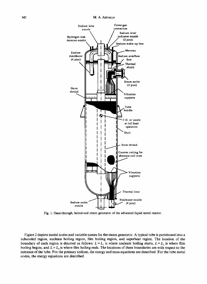
The current design of the Department of Energy's ALMR uses a once-through, helical-coil steam generator. It is a vertical, sodium-to-water counterflow shell-and-tube heat exchanger. Figure I shows the steam generator design to be modeled. The system boundaries are formed by the inlet and outlet nozzles of the liquid sodium on the primary side and the feedwater inlet and steam outlet on the secondary side.
The hot secondary sodium coolant coming from the hot leg of the intermediate heat transport system enters the top of the steam generator and flows downward in the shell side and leaves the steam generator at the bottom. Subcooled feedwater from the feedwater header enters the steam generator at the bottom through four feedwater nozzles. The water gains heat from the hot sodium as it flows upward inside the helical tubes. Once it reaches saturation temperature, the water continues upward through a nucleate boiling region, a film boiling region, and a superheat region in a single pass upward through the steam generator.
3. MATHEMATICAL FORMULATION OF THE MODEL
This section deals with the development of the mathematical model of the steam generator. The general assumptions, the conservation equations, the heat transfer and hydraulic correlations, and the equations of state are presented.
f Based on work performed by Oak Ridge National Laboratory, managed for the U.S. Department of Energy under contract DE-AC05-84OR21400 by Martin Marietta Energy Systems, Inc.
541
542 M.A. ABDALLA
Sodium inlet nozzle
Hydro I detecto
Cover gas connection
te
p line
Sod distri
(4 p o w
Out( shro~
;let
/
I
Sodium o u t l e t / ~ nozzle
5sle at full load operation
Shell
,...- Inner shroud
Counter coiling for alternate coil rows /
~ Vibration supports
/ Thermal liner
Feedwater nozzle ] . . . .1 (4 pies)
Fig. I. Once-through, helical-coil steam generator of the advanced liquid metal reactor.
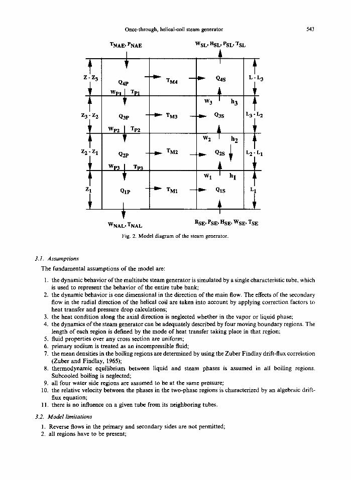
Figure 2 depicts model nodes and variable names for the steam generator. A typical tube is partitioned into a subcooled region, nucleate boiling region, film boiling region, and superheat region. The location of the boundary of each region is denoted as follows: L = Lt is where nucleate boiling starts, L = L 2 is where film boiling begins, and L = L 3 is where film boiling ends. The locations of these boundaries are with respect to the entrance of the tube. For the primary sodium, the energy and mass equations are described. For the tube metal nodes, the energy equations are described.
Once-through, helical-coil steam generator 543
Z - Z 3
1
Z~ - Z 2
TNAE, PNAE
q
J
---"1~ TM4
- ~ TM3
Z 2 - Z 1 - ~ TM2
Q4P
WpI ~ Tp1
Q3P
Wp2 I Tl~
Q2P
Wp3 ~ TP3
QIP Z 1 - ~ TM1
WNAL, TNAL
WSL' HSL, PSL, TSL
-
- - I I ~ Q4S
W 3 ~ h 3
- - ~ Q3S
W 2 ~ h 2 !
--- - I ~ Q2S ]~
W 1 ~ h 1
- - -I~.- QIS
t
L-~
r_
L 3 L 2
r_
L 2 L 1
I_
L
RSE, PSE, HSE, WSE, TSE
Fig. 2. Model diagram of the steam generator.
3.1. Assumptions
The fundamental assumptions of the model are:
1. the dynamic behavior of the multitube steam generator is simulated by a single characteristic tube, which is used to represent the behavior of the entire tube bank;
2. the dynamic behavior is one dimensional in the direction of the main flow. The effects of the secondary flow in the radial direction of the helical coil are taken into account by applying correction factors to heat transfer and pressure drop calculations;
3. the heat condition along the axial direction is neglected whether in the vapor or liquid phase; 4. the dynamics of the steam generator can be adequately described by four moving boundary regions. The
length of each region is defined by the mode of heat transfer taking place in that region; 5. fluid properties over any cross section are uniform; 6. primary sodium is treated as an incompressible fluid; 7. the mean densities in the boiling regions are determined by using the Zuber Findlay drift-flux correlation
(Zuber and Findlay, 1965); 8. thermodynamic equilibrium between liquid and steam phases is assumed in all boiling regions.
Subcooled boiling is neglected; 9. all four water side regions are assumed to be at the same pressure;
10. the relative velocity between the phases in the two-phase regions is characterized by an algebraic drift- flux equation;
11. there is no influence on a given tube from its neighboring tubes.
3.2. Model limitations
1. Reverse flows in the primary and secondary sides are not permitted; 2. all regions have to be present;
544 M.A. ABDALLA
3. primary flow must be single phase; 4. feedwater flow must be single phase.
3.3. General conservation of mass and energy equations
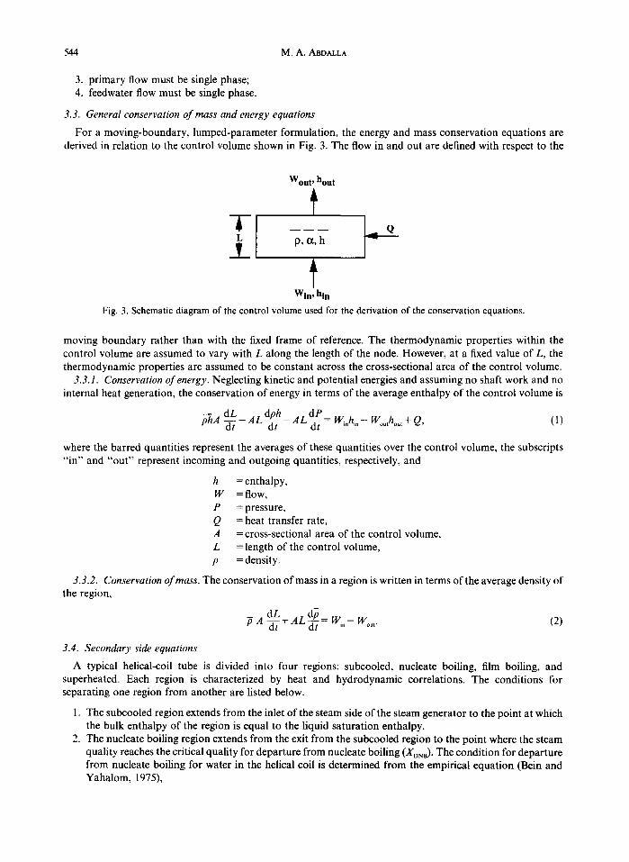
For a moving-boundary, lumped-parameter formulation, the energy and mass conservation equations are derived in relation to the control volume shown in Fig. 3. The flow in and out are defined with respect to the
-I-
Wout, hout
p , a , h
Win, hin Fig. 3. Schematic diagram of the control volume used for the derivation of the conservation equations.
moving boundary rather than with the fixed frame of reference. The thermodynamic properties within the control volume are assumed to vary with L along the length of the node. However, at a fixed value of L, the thermodynamic properties are assumed to be constant across the cross-sectional area of the control volume.
3.3.1. Conservation of energy. Neglecting kinetic and potential energies and assuming no shaft work and no internal heat generation, the conservation of energy in terms of the average enthalpy of the control volume is
phA-- -d-[dL _ AL dph~_- AL dP~ = Wi.h~n- Woutho,,t + Q, (1)
where the barred quantities represent the averages of these quantities over the control volume, the subscripts "in" and "out" represent incoming and outgoing quantities, respectively, and
h = enthalpy, W = flow, P = pressure, Q = heat transfer rate, A = cross-sectional area of the control volume, L = length of the control volume, p = density.
3.3.2. C•nservati•n •f mass. The c•nservati•n •f mass in a regi•n is written in terms •f the average density •f the region,
3.4. Secondary side equations
A typical helical-coil tube is divided into four regions: subcooled, nucleate boiling, film boiling, and superheated. Each region is characterized by heat and hydrodynamic correlations. The conditions for separating one region from another are listed below.
1. The subcooled region extends from the inlet of the steam side of the steam generator to the point at which the bulk enthalpy of the region is equal to the liquid saturation enthalpy.
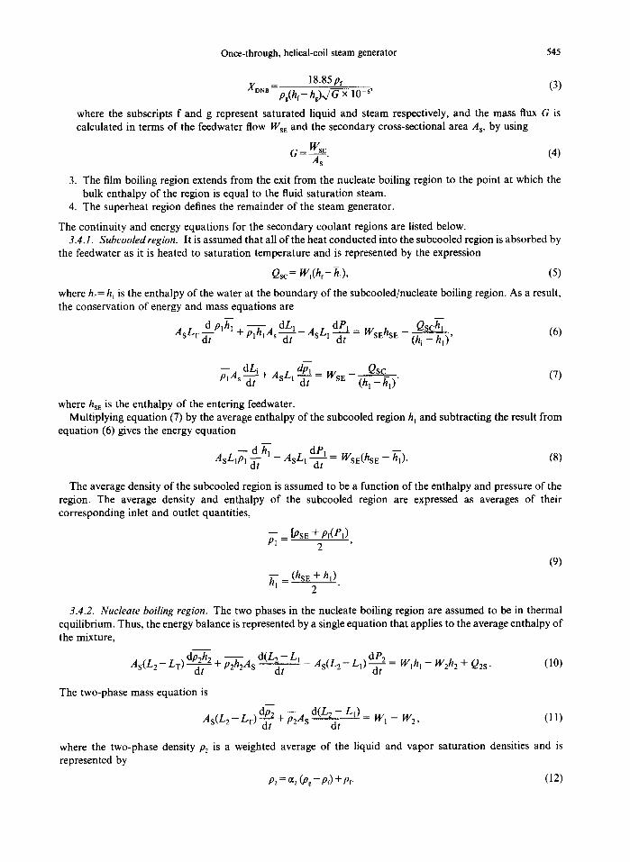
2. The nucleate boiling region extends from the exit from the subcooled region to the point where the steam quality reaches the critical quality for departure from nucleate boiling (XDNB). The condition for departure from nucleate boiling for water in the helical coil is determined from the empirical equation (Bein and Yahalom, 1975),
Once-through, helical-coil steam generator 545
18.85 pf (3) J(or~B -- pg(hf- hg)x/G x 10 -6,
where the subscripts f and g represent saturated liquid and steam respectively, and the mass flux G is calculated in terms of the feedwater flow WsE and the secondary cross-sectional area A s, by using
6 - wsE (4) A s "
3. The film boiling region extends from the exit from the nucleate boiling region to the point at which the bulk enthalpy of the region is equal to the fluid saturation steam.
4. The superheat region defines the remainder of the steam generator.
The continuity and energy equations for the secondary coolant regions are listed below. 3.4.1. Subeooledregion. It is assumed that all of the heat conducted into the subcooled region is absorbed by
the feedwater as it is heated to saturation temperature and is represented by the expression
Qsc = W,(hr- h~), (5)
where hf = h~ is the enthalpy of the water at the boundary of the subcooled/nucleate boiling region. As a result, the conservation of energy and mass equations are
~-t - - dLl - A L dPl Qschl AsLT Plhl +PlhlAs"-~ s l--d't "= WsEhsE ( h i _ h i ) ' (6)
- - dLi d~ll Qsc plAs--d7 + AsLl ~ = WSE -- ( h i - h i ) ' (7)
where hsE is the enthalpy of the entering feedwater. Multiplying equation (7) by the average enthalpy of the subcooled region h~ and subtracting the result from
equation (6) gives the energy equation
d~ hi - A L dPl AsLIPl S 1 " ~ = WsE(hsE -- h i ) . (8)
The average density of the subcooled region is assumed to be a function of the enthaipy and pressure of the region. The average density and enthalpy of the subcooled region are expressed as averages of their corresponding inlet and outlet quantities,
- - [PsE + Pf(el) P l - 2 '
(9)
hi - (hsE + hi) 2
3.4.2. Nucleate boiling region. The two phases in the nucleate boiling region are assumed to be in thermal equilibrium. Thus, the energy balance is represented by a single equation that applies to the average enthalpy of the mixture,
dp2h 2 - - d(L 2 - L I dP2 As(L2- L T ) - - - ~ + p2h2As -dt As(LE- LI)-~-~ -= Wlhl - W2hz + Q2s . (10)
The two-phase mass equation is
As(L 2 - Lr) dP2 + ~ A s d(L2~ LI) - W l - W2, (11) at tit
where the two-phase density P2 is a weighted average of the liquid and vapor saturation densities and is represented by
P2 = ~2 (P~- Pf) +Pf. (12)
546 M.A. ABDALLA
At an elevation L inside the nucleate boiling region, the product of density and enthalpy is
p(L)h(L) = ~(L) (p~hg - prhf) + pehr. (13)
Because the saturation properties Pr, P~, hr, and h, are constant over the region, the average ofph over L from top to bottom of the nucleate boiling region can be expressed in terms of the average void fraction,
p2h2 = o¢2(pghg- prhf) + p~hr, (14)
where
and
h 2 = (1 - X) hr+ Xhg (15)
l h~ I ~ 2 l (16)
The Zuber-Findlay Drift Correlation, an algebraic correlation between the flow quality and the void fraction, is used to determine the average quantities at any level. The average void fraction is represented by
X(L) X(L)
where
a = Cop~ + P ~ V and b=Co -C°p*. (18) Pr G Pr
Both the distribution parameter C O and the drift velocity Vg are treated as constants throughout the region. The volume weighted-average void fraction of the region is
L; off L ) d L
~22 - L ' (19) L z - L I
The flow quality X is assumed a value of zero at L = L~ and a value of)(2 at L = L2. By assuming uniform heat flux, a relationship between flow quality and level can be obtained:
d X = ~ L . (20)
Substitution of Equations (17) and (20) into Equation (19) gives an integral relation in terms of X alone:
- - i x : x x ~2 = ~--~x j, a ~ d , (21)
where X~ = 0 and AX= X 2 = XDNB. Taking the integral of equation (21) results in
- - 1 a b ( a + b~fDNB ) (22) ~t 2 = + b--~D.NB In
The algebraic relationship for average void fraction ~2 is a function of pressure, mixture quality, and mass flux, whereas the flow quality, equation (3), is assumed to be a function of pressure and mass flux only. To avoid computational difficulties for small flow quality or small mass flux, the arguments of the average void fraction are limited to 0.001 < X < 0.99 and G > 0.25 ft/s.
Taking the required partial and total derivatives required and substituting in equations (10) and (11) result in the energy and mass equations of the nucleate boiling region respectively:
-p2h2as ' + QlshL - As(L2 - L0(pghg - ?rhr) \ (O--G + = Q2s (h 1 - h i )
Once-through, helical-coil steam generator 547
dL2 + W2h 2 + As(L 2 - L1) + P2h2As dt
" h l a ~ + a~ax\
\ gaP a P /
+(1-~)( aPPfahr+hrOPfaP)-I
F /a~ o~ax',] - , d/ . , - - / ( ' ° ' - P f ) l t - b " ~ + ~ ) l d t >
L+c + (l-C)- J
dP (23)
(24) i B
= Qls _ As(L 2_ Li ) (pg_pr) (a~z + o ~ 2 a X ) dG (h| - ~ ) t a g T £ ~ / - d 7
3.4.3. Film boiling region. The derivation of the conservation of energy and mass equations for the film boiling region is similar to that for the nucleate boiling region. The average ofph over the film boiling region is
p3h, = ¢x~(psh 8 - prhr) + p:h r, (25)
where
P3
The average density and void fraction of the region are expressed as
P3 = ~q(Pg - Pf) + Pr
(26)
(27)
(28)
dP - - dL 2_p3h3Asd~ 3 --~ + P3h3As "~-
- - 1+ a , [a+bX '~ •3 = b b (--f~Z~_ ~ 'n t --~--~-~- ] ,
and the energy and mass equations of the film boiling region are
aX aP /
- As (L3- L2) +-~33 ~Pgap + hg~-gp )
- - / ahf h aPf ~ + (1 - "3) .v .{P~ + qF) - 1
O , ~ /aS a~ axx dG + W2h2- W3ha=-Q2s + (hl--'~-r') + n ' As(L3 - L 2 ) ( P s h s - p f h f ) t - ~ + -Y£ ~ ) -d-; (29)
(0~ 3 + a~ 3 OX'~ dG - - dL 2 _ - - dL 3 As(L3 - L2)(Pg - Pf) \ - ~ -~-~-~ ]-~-~= - P3As--~7- P3As--~ -
F /a~ a~axq
w3 As( " - L . , o i_ + - - L2) + ~ _ ~ p + ( l _ ~ ) a p f
3.4.4. Superheat region. For the superheat region, the conservation of mass equation is
(30)
548 M.A. ABDALLA
m
d(L L3) 1
~- As(L - L 3 ) ~ t 4 = W 3 - - W4, "04As dt
and the conservation of energy equation is
As(L - L3)P44 ~ t 4 - As(L - L3) TdP4 = W3(h3 - h4) - WsL(hsL -- ~4) + Q4s.
(31)
(32)
where I4:4= Wst and t14= hsL. The average density and enthalpy of the superheat region are expressed as averages of their corresponding inlet and outlet quantities:
- _ 0 3 + P4) '04 2 '
and
h4- (h8 2 h4!; (33)
and the average enthalpy is assumed to be a function of the enthalpy and pressure of the region. Taking the necessary partial derivatives and substituting into equation (32) results in the energy equation
W 3 + p-44As ~ - As(L - t ~ OP4 dhsL _(_ As(L - L3) OP4 dP4 "-~3J ah dt - 0P dt - Wse" (34)
Equations (7), (8), (23), (24), (29), (30), (31), and (34) form a set of eight nonlinear differential equations that contain 14 variables that were reduced to eight by making the following assumptions:
P1 = P2 = P3 = P4 = PSL, hi = hf(PsL), (35)
h 2 = hr(1 - XXDNa ) + XXDNahg, h3 = hg(Pse ).
The eight nonlinear differential equations are written in the following matrix form for numerical solution by Gaussian elimination (Burden et al., 1981):
A X = B (36) with
X = [h,, W2, w3,L,,L2,L3,PsL,h,] T, (37)
where L~, L2, and L 3 represent the location of the subcooled, nucleate boiling, and film boiling boundaries respectively. They represent the tube lengths from the feedwater entrance of the steam generator. Pse and hse represent the pressure and enthalpy of the leaving steam respectively. W2 and W 3 represent the secondary flow rate across the nucleate/film boiling boundary and the film boiling/superheat boundary. The h~ represents the enthalpy leaving the subcooled region.
To reduce the condition number of A, the flows are scaled by 106. The second and third columns of the coefficient matrix A are multiplied by 106. The answers for the secondary mass flow rates W~, W2, W 3 are also multiplied by 106 .
3.5. Primary side equations
The primary side is divided into four regions by using the moving boundary defined by the secondary side equations. The primary volumes provide temperatures at the inlets and exits to define heat transfer rates conveniently. Both mass balance and energy balance equations are considered for describing the dynamics of each primary node. The primary sodium flow is assumed to remain single-phase liquid during all load- following transients. The sodium is treated as an incompressible fluid. The mass and energy equations are identical in all four of the primary side control volumes.
The mass balance equation is
W o u t = - d V w'° - ?-dF (38)
With the assumption that the expansion work term VdP/dt is negligible, the conservation of energy equation is
Once-through, helical-coil steam generator 549
_ dh Wout(-~_ho,,)+ W~.(h,.--h)-Qp. p V - ~ = (39)
Because of the negligible dependence of the enthalpy of the liquid sodium on pressure, the sodium enthalpy of a primary node is assumed to be a function of temperature only. Thus, equation (39) becomes
d Tp_ [ Wo,,(h- ho,t) + l,V~.(h~, - h) - Qe] (40) dt -~ V Cp
The angle of incline of the helical tube with respect to the horizontal axis is calculated by using
0 = s i n - l ( Z ) , (41)
where Z is the height of the tube and L is the overall tube length. The heights of the subcooled, nucleate boiling, and film boiling regions are
Z~ = L~ sin 0, Z 2 = (L 2 - L 0 sin 0,
Z3 = (L3-L2) sin 0, Z4 = (L-L3) sin 0. (42)
Because each region has moving boundaries, the inlet primary flow rate to each node is computed by using the expressions
Wp, = Wi,--p--lAp~, Wp,=. W , . - E A p ~ , Wp3= Wi,-~Ap dZ'dt. (43)
From equation (4), the equations of the temperature of the primary side nodes are
dTpl _ [ W~.(h~. - hp.) - Wp~( hp~ - h~,) - Q4P] (44) dt [fi, VotCp] '
d E : _ [ Wp,(h.a - he:) + We2(he2 - h2a) - Q3P] (45) dt [/~', Vp_~ Cp] '
dTp3 _ [ Wp:(h2a - hp3) + Wp3(ha3 - h3a) - Q2a] (46) dt [P3Vp3Cp] '
d TNA L -- [ Wp3(h3a- hNAL) -- QW] (47) dt [ff4 Vp4Cp] '
where
Vpl = ApZj, Vp2 = Ap(Z:- ZI),
= J hpt, Wp1/>0 hlB
I hp2, Wpl ~<0'
3.6. Metal temperature equations
(48)
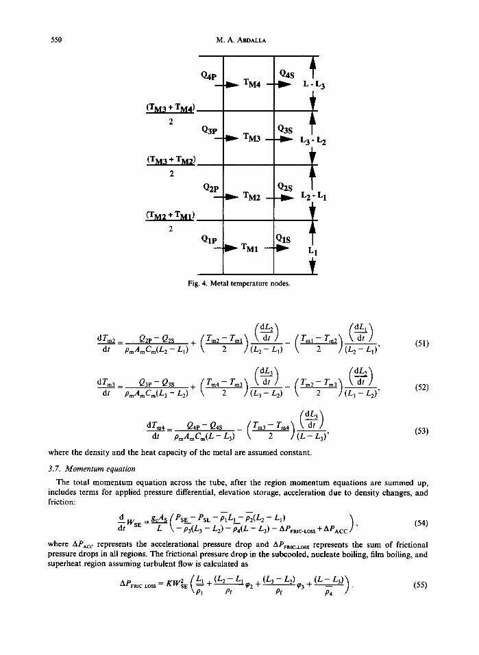
The metal side is divided into four nodes. With the moving boundary approach, the mass transfer due to the moving boundaries between regions has to be taken into account when deriving the energy equation associated with each metal node shown in Fig. 4. It is assumed that if the boundary is moving with a speed ofdL/dt, it will add or subtract an amount of heat at a rate of PmAmCmTmdL/dt. The dynamic equations for the energy storage in the metal tube are formulated from the energy balance in the tube. The energy equations for the four metal nodes are
dTml Q1P- Qls t- ( Tm2- TmI ) dL' (50) dt PmAmCmLl 2 dt '
Vp3 = .4p(Z 3 - Z2) , Vp4 = A p ( Z - Z3).
The enthalpy of the primary fluid at the boundaries of the control volume depends on the sign of the flow rate through the boundary:
h2a={ hP2'WP2~O { hP3' WP3 ~ 0 (49) hp3, Wp2~0' h3B = hNAL ' Wp3~0"
550 M.A. ABDALLA
Q4P
(TM3+
2 Q3P
2
Q2P
(TM2 + TM1)
2
Q1P
Q4S TM4 --.-D~
Q3s TM3
Q2S TM2
Q1S TM1 - - ~
Fig. 4. Metal temperature nodes.
A
L, L 3
,r.
L 3 L 2
L 2 L 1
1
| 1
dt PmAmCm(L2 - Ll) 2 (L 2 - LI) ~ (L 2 - LI)' (51)
dZm3- a3P-Q3s + Tin4-Tm3)\ dl ] (Zm2-Zm3) \ dl / dt PmAmCm(L3 - L2) 2 (L 3 - L2) 2- (L 3 - L2)'
(52)
dTm4_ Q4P-Q4s _ - Tin4" ~ \ dt ,/ dt PmAmCm(L - L3) ( Tm3 "2 ] ( -~- L-~3)' (53)
where the density and the heat capacity of the metal are assumed constant.
3.7. Momentum equation
The total momentum equation across the tube, after the region momentum equations are summed up, includes terms for applied pressure differential, elevation storage, acceleration due to density changes, and friction:
d WsE-gcAs(PsE--- P s c - P l L I ~ p 2 ( L 2 - LI) ) (54) - T \ - P3(L3 - L2) - P4(L - L3) - APFR~C.LOSS + APAc c '
where APAc c represents the accelerational pressure drop and APvR~C_~OSS represents the sum of frictional pressure drops in all regions. The frictional pressure drop in the subcooled, nucleate boiling, film boiling, and superheat region assuming turbulent flow is calculated as
Once-through, helical-coil steam generator 551
To obtain the frictional pressure loss for two-phase flow, the single-phase friction coefficient is corrected by the Martinelli Nelson empirical approximation (Martinelli and Nelson, 1948) of the two-phase multiplier. The two-phase multiplier is represented as a function of steam quality, pressure, and mass flow rate as
~ = GTP[ll2 ( 'f ) ~01824~ - 1.0 "DNBJ + 1.0, (56)
where
_1 1 G G 1.36 + 0.0005 PSL + 0 - ( ] " ~ ) -- 0.000714 PSL ( ] - ~ ) , (~g06) < 0.7
GTP -11.26 _ 0.0004 PSL + 0.119 (~_6) ] 0.00028 PSL (~_~) ( ~ ) ~0 7
The flow quality along the tube, assuming uniform heat flux, is
(L - L,) x= x, + (x2- x,) ~ ,
dX- (X2 - XI) a t (L 2- L,) - -"
Solving for dL gives
d r , - (L2- L~) ely - (X2- X~)-""
The value of the two-phase multiplier ~0 averaged over a boiling region is
= ~-~ @(X')dL.
Substituting equation (60) into equation (61) yields
1 L
t , \ x 2 - x l / (x2 - x l ) ~,, For the nucleate boiling region,
For the film boiling region,
(57)
(58)
(59)
(60)
(61)
(62)
3.8. Summary of heat transfer correlations In this section, the heat transfer characteristics of the steam generator and the corresponding correlations are
presented. These correlations are used in both steady-state and dynamic thermal-hydraulic transients. Also,
- - k(l - - yI.824"t ~DNBJ (66)
@3 = 1 + 1.824 (1 -- XDNB)"
The accelerational pressure drop is due to the velocity change as the fluid accelerates from liquid phase to vapor phase. The term is calculated by using the equation
APAcc=KW~E(WSE)2( 1_~ 1 ) . (67) \ As / PSE PSL
1 - - _ 1 . S ( kX°'Sz4+ 1)dX, (65) @3 (1 - XONB)xtm,
~"-~2 = I'--~x~B( kX°824 + l)dX, (63) XDNB 0
_ _ / _ I , - 0 . 8 2 4
~z = 1 + '~DNa (64) 1.824
552 M.A. ABDALLA
the physical and thermodynamic properties of the primary liquid sodium, water/steam mixture, and tube metal used in the steam generator model are presented.
The relationships used for the primary and secondary heat transfer effectivenesses were obtained from notes from personal communication with T. L. Wilson of Oak Ridge National Laboratory and are reproduced here. The heat transfer from the sodium to the tube metal and from the tube metal to water is assumed to be due entirely to convection. The heat transfer from the hot sodium to the metal tube is calculated by using
a iP : UEFp~(TM- T J , (67)
and the heat transfer between the tube metal and the secondary node is given by
Q~s: UEFs~(Tm,- TM)' (68)
where T M is the metal temperature, Tom is the temperature of cold fluid in, th~ o is the temperature of hot fluid in, and UEV ~ and UEFS~ are primary and secondary effectiveness coefficients of the counterflow geometry of the tube metal. Then,
with
2g - gZ( 1 - CR) UEFP~--f+ g--fg(1 -- CR) (2g + 3) (69)
2g -- g2( 1 -- CR) (70) UEFS~-- 1 - - f+g- -g (1 - - f ) (1 -- CR)'
f (71) g = RCR 1 -J"
U, (72) f: U, + Uc'
-UU_PL ( I - C R ) R = e c. , (73)
1 ( 7 4 ) U H - 1 a '
+ h H 2k
1 U c - - - , (75)
1 a
h c 2k
C. (76) CR - C-~'
C. = (WCp)H, (77)
C c = (WCp) o (78)
where
h = heat transfer coefficient, U = overall heat transfer coefficient, L = length of tube, P = wetted perimeter, W = fluid flow rate, Cp = specific heat of fluid, a = thickness of tube, k = tube conductivity,
and the subscripts H and C denote hot and cold fluid respectively. The heat transfer coefficients used in the secondary side of the steam generator are computed by using the
empirical correlations given below. 3.8.1. Subcooled region. The convective heat transfer coefficient for the fully developed turbulent flow in
the subcooled region is calculated from the Dittus-Boelter correlation (Lahey and Moody, 1979):
Once-through, helical-coil steam generator 553
Nu = 0.023 Re °'s Pr o." , (79)
where Nu, Re, and Pr are Nusselt, Reynolds, and Prandtl numbers respectively. The total heat transfer coefficient is dependent on density, velocity, viscosity, and conductivity of the fluid. However, the density and velocity of the fluid are more apt to change value during a given transient than are other properties, indicating that they are more predominant. Therefore, the simplified form is used for the heat transfer coefficient:
h = k0 W ~.s, (80)
where kc is a multiplying factor and W is the secondary mass flow rate. The Dittus-Boelter correlation is valid for fully developed turbulent flow in smooth tubes. It is applicable for fluid with small temperature differences and 0.7 < Pr < 10,000, Re > 10,000, and LID > 60 (Lahey and Moody, 1979). The fluid properties are evaluated at the fluid bulk temperature at the region of interest.
3.8.2. Nucleate boiling region. The heat transfer coefficient for the two-phase nucleate boiling region is calculated by using Thom's correlation (Thom, 1964). This correlation is sensitive to the pressure of the system and is presented by
hTho m = 005 ( 8 1 ) L o . - b 3 5 j - '
and the heat transfer Q is calculated as
where
Q = hTh°~(Twa . - Tsar), (82)
P = pressure in psia, Twa~ = wall temperature, TsA T = saturation temperature of the secondary fluid.
3.8.3. Film boiling region. The heat transfer coefficient for the two-phase mixture within the film boiling region is obtained from the Modified Bishop correlation (Bishop et al., 1965): [ )00 ,
h = KW °'8 XXDN a + (1 - X X D N B ) fig , (83) Pf
where the effects of the Prandtl number are neglected. 3.8.4. Superheat region. Similar to the subcooled region, the superheat single-phase region uses the same
simplified region Dittus-Boelter correlation:
h = K W °'8. (84)
3.8.5. Primary side. The heat transfer correlation for the primary sodium flow is obtained from the Marosca-Dwyer correlation (Bruens et al., 1975)~ The Nusselt number is expressed as
Nu = 6.66 + 3.12 d6-~o + 1.184 ~oo + 0.0155(~Pe) °86 (85)
with
- - 1 . 8 2
~ u = l - p r ( ( 0 . 4 8 2 4 + 0 . 8 8 7 ) 1 2 + 2.15 x 10- 3 1 (0.4824 + 0.88_~) Rel °ss}) 14' (86)
where p/do is the pitch-to-diameter ratio. Neglecting the Prandtl number effect and for the primary flow range of interest, the heat transfer coefficient for the primary side coolant is
h = KWNAE, (87)
where Wr~AE is the primary sodium flow rate.
3.9. Thermodynamic and physical properties of sodium, water, and tube metal
The properties of liquid sodium, steam/water, and the metal tube used in the development of the dynamic model of the steam generator are listed in this section.
554 M.A. ABDALLA
3.9.1. Sodium properties. The thermodynamic relationships between temperature, specific heat, and enthalpy for the primary sodium were obtained from internal correspondence from J. C. Cleveland et al., Oak Ridge National Laboratory.
3.9.1.1. Sodium density. The liquid sodium is treated as an incompressible fluid. Its density is represented as a function of temperature only:
p--- 59.566 - 7.9504 x 10⁻³T~ - 0.2872 x 10⁻⁶T~ + 0.06035 x 10-gT 3, (88)
where p is in pounds mass per cubic foot and TF is in degrees Fahrenheit. This equation is valid for 208 < T F < 2500"F.
3.9.1.2. Specific heat of sodium. The specific heat of sodium is considered to be a function of temperature only. The specific heat at constant pressure of liquid sodium is obtained from the expression
Cp=0.389352 - 1.10599 x 10⁻⁴TR+3.41178 x 10⁻⁸T~t, (89)
where Cp is the specific heat in British thermal units per pound mass per degree Fahrenheit and T R is the temperature in degrees Rankine.
3.9.1.3. Enthalpy of sodium. The enthalpy is obtained from
T h(T) = j Cp(T ' )dr ' , (90)
TRef
where Cp(T') is given in equation (89) and Ta0 f is taken as 100*C. 3.9.2. Steam/water properties. The physical and thermodynamic properties of the steam/water mixture are
evaluated by using the Modular Modeling System (1985) steam-water library, which contains a set of steam/ water property routines. Some of these routines are polynomials, and others are table interpolations of the thermodynamic properties of steam and water. Given the pressure and the enthalpy, the subroutines determine the water phase and the appropriate density, temperature, and partials of density with respect to pressure and enthalpy. In the derivation of the state equations of the two-phase regions, the water properties are determined as a function of the void fraction of the corresponding region. The saturated vapor and liquid properties needed in these state equations are determined from the appropriate functions of pressure.
3.9.3. Physical properties of the metal tube. Both the density and the specific heat of the metal tube are assumed constant:
pm= 486.7 lbm/ft 3 and Cm =0.135 B.t.u./lb m- OF. (91)
4. RESULTS AND DISCUSSION
This section presents the transient response of selected variables to ramp changes in the boundary conditions for flow, temperature, and pressure. To simulate steady-state conditions of the steam generator at 100% rated power, the departure from the nucleate boiling correlation [equation (3)] and the heat transfer effectiveness for each of the primary and secondary regions were modified by correction factors such that the primary and secondary heat balance became equal to 479 MW(t). These correction factors were introduced to account for the helical geometry of the tubes and its effects on the heat transfer coefficients.
The simulated steady-state conditions at 100% rated power are listed in Table 1. These conditions were obtained by using a proportional-integral controller to control the pressure of the steam to its set point such that the steam flow rate is
QSP t WSL= WS" (Q- -~ax)E!K ' (PsL- -Psp)d t+Kp(PsL- -PsP) ] ' (92)
where K~ and Kp are the integral and proportional gains, Ws~ ~ is the initial steam flow rate, QsP is the set point of the secondary heat rate, Qm,, is the maximum value of the secondary heat rate, PsL is the pressure of steam, and PsP is the pressure set point.
To demonstrate the model's ability to simulate steam generator behavior for a wide range of perturbations, transients induced by introducing perturbations in primary coolant inlet temperature, feedwater flow rate, and outlet steam pressure are investigated. An 80% decrease in feedwater flow transient is also investigated.
Once-through, helical-coil steam generator 555
Table 1. Simulated steady-state conditions at 100% rated power
*/,Heat load [MW(t)] 477.2 Inlet feedwater temperature (°F) 380 Outlet steam temperature (OF) 830 Outlet steam pressure (psia) 1800 Inlet sodium temperature (°F) 864 Outlet sodium temperature (°F) 577 Feedwater flow rate (Ibm/h) 1.6056 x 10⁶ Sodium flow rate (Ibm/h) 1.8230 x 10⁷ Length of subcooled region fit) 95.823 Length of nucleate boiling region (ft) 58.156 Length of film boiling region (ft) 7.782 Length of superheat region (ft) 81.24 Temperature of primary node 1 (OF) 801.87 Temperature of primary node 2 (OF) 773.08 Temperature of primary node 3 (OF) 659.29 Temperature of metal node 1 (OF) 558.71 Temperature of metal node 2 (°F) 635.36 Temperature of metal node 3 (°F) 642.52 Temperature of metal node 4 (OF) 779.98 Steam quality 0.7991
These t ransients are of special interest because they provide in format ion on the s team genera tor nonl inear behavior . For each case, the input variable under s tudy is per turbed f rom its s teady-state opera t ing point by a 10% ramp increase, with the o ther input variables held constant . In all cases, a per iod of s teady-state opera t ion for 500 s is s imulated before the beginning of the t rans ient to ensure tha t the s imulat ion is stabilized and that subsequent var ia t ions are due to the pe r tu rba t ion induced ra ther than to an offset in the initial condit ions.
One o f the l imitat ions o f the s team genera tor model is t ha t the subcooled, nucleate boiling, film boiling, and superheat regions mus t be present dur ing all investigated transients. To prevent the d isappearance of the film boil ing region in the 80% reduct ion in feedwater flow transient , the s team quali ty was not al lowed to increase beyond 0.99.
4.1. 10% increase in primary coolant inlet temperature
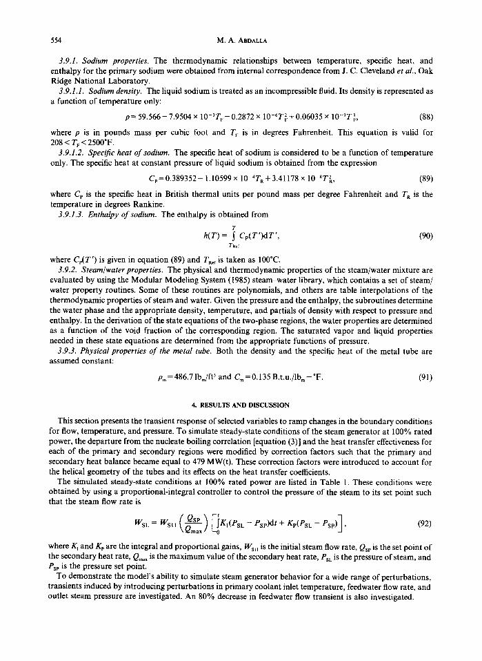
Figure 5 depicts the inlet and outlet sodium tempera tures and the s team outlet t empera ture dur ing the 10%
1000
950
/-~ 900 o ~
~'~ 850
~ 800
750 ©
~ 7oo
650
I I I I I I I
s S
• . . . . . , . . - ° ' ' " . . . . . . . . . . . . . . . . . . . . . . . . . . . . . . . . . . . . . . . . . . . . . . . . . . . . . . . . . . .
600
5 5 0 h i i I i I i I i I i I i I i
0 200 400 600 800 1000 1200 1400 1600
Time (s) Fig. 5. Inlet and outlet sodium temperatures and the steam outlet temperature following a 10% increase in
inlet sodium temperature transient.
increase in inlet sodium tempera tu re t ransient . The inlet sodium tempera ture is held cons tan t a t 864°F for 500 s and then allowed to increase by 86.4 to 950.4°F in 200 s, where it is ma in ta ined cons tan t for the rest of the t ransient . The increase in sodium inlet t empera ture causes an increase in the rate of heat t ransfer f rom the
556 M.A. ABDALLA
O 0~,.~
@
160
140 1
120 /
100 i
,0 ii iiiiiiiii . 60 . . . . . . . . . . . . . . . . . . . . . . . . .
".....
40 "".,..
I I I ' I I
Subcooled .N.~leat~ bo!!!.~g _Film _b_oil_in_g Sup_erh_eat
"'"'---. ...............................................................
20
0 --:----i . . . . 7---] . . . . , . . . . [---7 . . . . r---:---T---:---7 . . . . :---] ..... 200 400 600 800 1000 1200 1400 1600
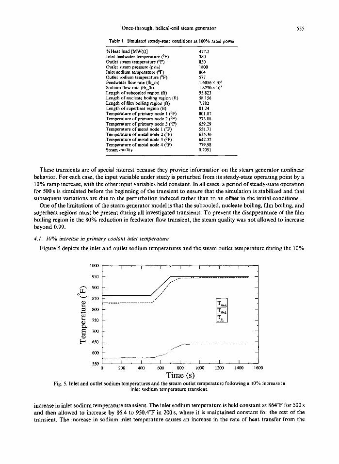
Time (s) Fig. 6. Lengths of the subcooled, nucleate boiling, film boiling, and superheat regions during the 10%
increase in inlet sodium temperature transient.
2120 ¢~ I I I I I I I
r~9
~-~ 2100
~ 2080
2060 ©
~ 2040
~ 2020
©
~ 2000 ' ' ' 0 200 400 600 800 1000 1200 1400 1600
Time (s) Fig. 7. Inlet feedwater pressure during the 10% increase in inlet sodium temperature transient.
primary side of the steam generator to the secondary side through the wall of the metal tube. As a result, an increase in all temperatures of the system is observed. The sodium outlet temperature and the steam outlet temperature are fairly sensitive to the increase in the sodium inlet temperature. Each temperature steadily increases to a new steady state. The sodium and steam outlet temperature increased by 67.3 and 104°F respectively. Figure 6 shows changes in the subcooled, nucleate boiling, film boiling, and superheat regions during the transient. As shown, the lengths of the subcooled, nucleate boiling, and film boiling regions decrease, whereas the length of the superheat region increases. Figure 7 depicts the inlet feedwater pressure during this transient. This pressure increases because of a larger pressure drop, with the largest pressure drop taking place across the superheat region. Figure 8 depicts the rate of steam flow out of the steam generator. The steam flow rate initially rises and then approaches its old steady-state value because there is no increase in feedwater flow to maintain the rise.
Once-through, helical-coil steam generator 557
xlO 6 1.67
1.66
E
~ 1 . 6 5
£ ~ 1.64
O 1.63
~ 1.62
£ G¢~ 1.61
I I
i
0 1 . 6 0 I , I , I I , I , I , I ,
200 400 600 800 1000 1200 1400 1600
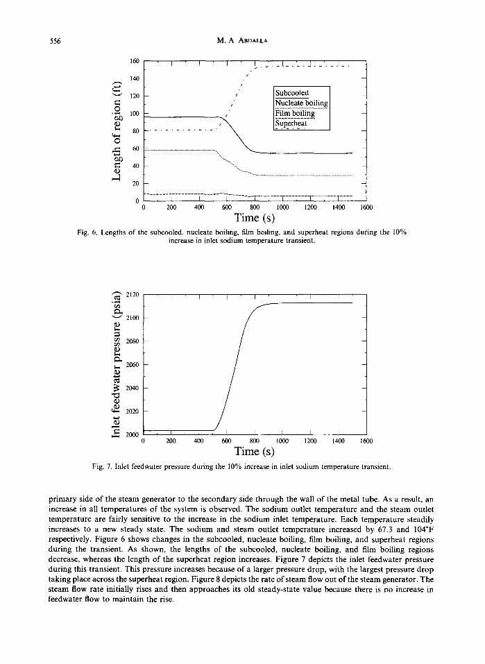
Time (s) Fig. 8. Steam flow rate out of the steam generator during the 10% increase in inlet sodium temperature
transient.
xlO 6 1.78
1 . 7 6
1.74
E 1.72 ,.Q
1.70
~ 1.68
~ 1.66 O
~ 1 . 6 4
1 . 6 2
1 . 6 0
I I I I I I I
/ [ oe water owl /
/
/ -; I , [ , I , I , I , I
200 400 600 800 1000 1200 1400
Time (s) 1600
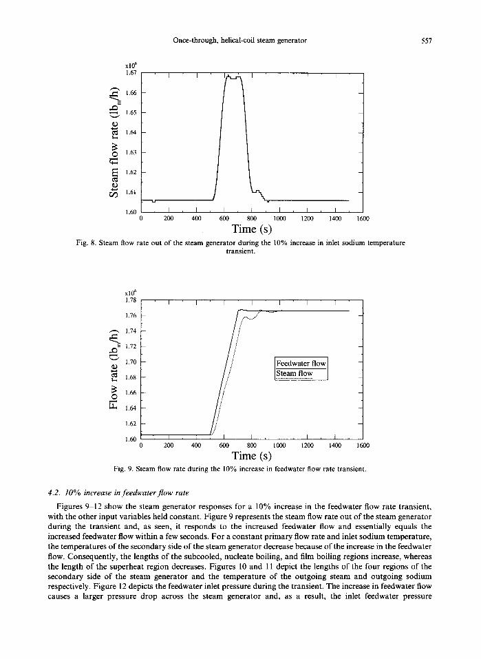
Fig. 9. Steam flow rate during the 10% increase in feedwater flow rate transient.
4.2. 10% increase infeedwaterflow rate
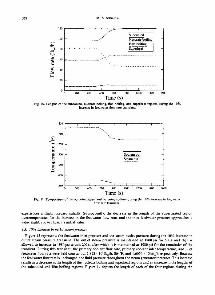
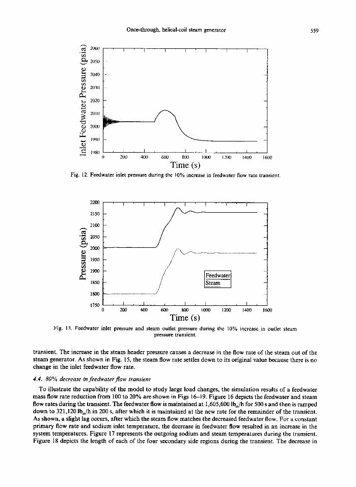
Figures 9-12 show the steam generator responses for a 10% increase in the feedwater flow rate transient, with the other input variables held constant. Figure 9 represents the steam flow rate out of the steam generator during the transient and, as seen, it responds to the increased feedwater flow and essentially equals the increased feedwater flow within a few seconds. For a constant primary flow rate and inlet sodium temperature, the temperatures of the secondary side of the steam generator decrease because of the increase in the feedwater flow. Consequently, the lengths of the subcooled, nucleate boiling, and film boiling regions increase, whereas the length of the superheat region decreases. Figures 10 and 11 depict the lengths of the four regions of the secondary side of the steam generator and the temperature of the outgoing steam and outgoing sodium respectively. Figure 12 depicts the feedwater inlet pressure during the transient. The increase in feedwater flow causes a larger pressure drop across the steam generator and, as a result, the inlet feedwater pressure
558 M.A. ABDALLA
Subcooled 100 ~ b o i l i n g " - " .........
80 . . . . . . . . . . . . . , Superheat
t ~ o-'~'"" . ~ 6 0 ~ ,
~: 40 0
20
0 , I i [ , I i [ , ~ i I , [ , 2 0 0 4 0 0 6 0 0 8 0 0 1 0 0 0 1 2 0 0 1 4 0 0 1 6 0 0
Time (s) Fig. 10. Lengths of the subcooled, nucleate boiling, film boiling, and superheat regions during the 10%
increase in feedwater flow rate transient.
8 5 0
800
o ~ ~ ' J 7 5 0
2 ~ 7 0 0
o
6 5 0
600
I I I I I I I . . . . . . . . . . . . . . . . . . . . . . . . . . . . . . . . . . . . . . . . . . . . . . . . . . .
" . .
Sodium out sr o.t ]
550 , I , I , I , I , I , I , I ,
0 2 0 0 4 0 0 6 0 0 8 0 0 1 0 0 0 1 2 0 0 1 4 0 0 1 6 0 0
Time (s) Fig. 11. Temperature of the outgoing steam and outgoing sodium during the 10% increase in feedwater
flow rate transient.
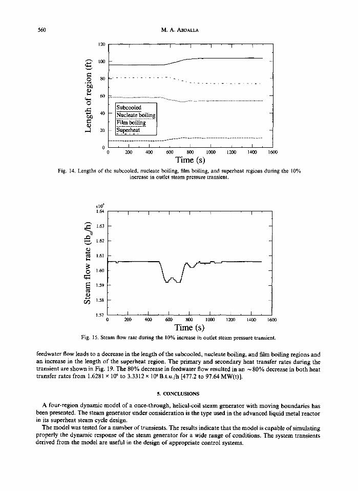
experiences a slight increase initially. Subsequently, the decrease in the length of the superheated region overcompensates for the increase in the feedwater flow rate, and the inlet feedwater pressure approaches a value slightly lower than its initial value.
4.3. 10% increase in outlet steam pressure
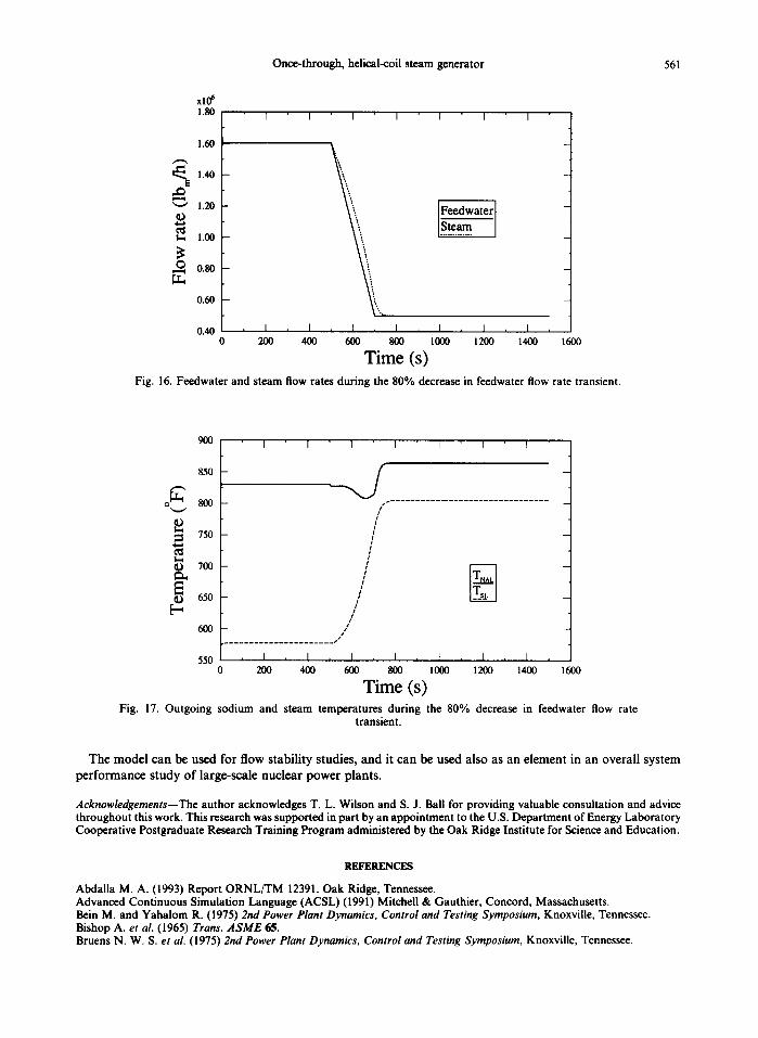
Figure 13 represents the feedwater inlet pressure and the steam outlet pressure during the 10% increase in outlet steam pressure transient. The outlet steam pressure is maintained at 1800psi for 500 s and then is allowed to increase to 1980 psi within 200 s, after which it is maintained at 1980 psi for the remainder of the transient. During this transient, the primary coolant flow rate, primary coolant inlet temperature, and inlet feedwater flow rate were held constant at 1.823 x 10⁷ Ibm/h , 864"F, and 1.6056 x 1061bJh respectively. Because the feedwater flow rate is unchanged, the fluid pressure throughout the steam generator increases. This increase results in a decrease in the length of the nucleate boiling and superheat regions and an increase in the lengths of the subcooled and film boiling regions. Figure 14 depicts the length of each of the four regions during the
Once-through, helical-coil steam generator 559
¢~t 2060
2050
~ 2040 r~ ~ 2030
~ 202O
t'~ 2010
2{K~1
1990
198(I
I I I I I I I
7 wv ....
, i , I I I I , I I
0 200 400 600 800 1000 1200 1400 1600
Time (s) Fig. 12. Feedwater inlet pressure during the 10% increase in feedwater flow rate transient.
2200
2150
2100
"~ 2050
2000
~ 1950
1850
1800
1750
I I I I I I I
",....---... ....................................................
/ Y
/ /
/
, I , I , L , I , I , I , I ,
200 400 600 800 1000 1200 1400
Time (s) 1600
Fig. 13. Feedwater inlet pressure and steam outlet pressure during the 10% increase in outlet steam pressure transient.
transient. The increase in the steam header pressure causes a decrease in the flow rate of the steam out of the steam generator. As shown in Fig. 15, the steam flow rate settles down to its original value because there is no change in the inlet feedwater flow rate.
4.4. 80% decrease in feedwater f low transient
To illustrate the capability of the model to study large load changes, the simulation results of a feedwater mass flow rate reduction from 100 to 20% are shown in Figs 16-19. Figure 16 depicts the feedwater and steam flow rates during the transient. The feedwater flow is maintained at 1,605,600 lbm/h for 500 s and then is ramped down to 321,120 lbm/h in 200 s, after which it is maintained at the new rate for the remainder of the transient. As shown, a slight lag occurs, after which the steam flow matches the decreased feedwater flow. For a constant primary flow rate and sodium inlet temperature, the decrease in feedwater flow resulted in an increase in the system temperatures. Figure 17 represents the outgoing sodium and steam temperatures during the transient. Figure 18 depicts the length of each of the four secondary side regions during the transient. The decrease in
560 M.A. ABDALLA
120
~ " 100
. ~ 80
~ 60 o
~ 40
© ~-1 20
0
I 1 I [ I I I
J
. . . . . . . . . . . . . . . ~ .
S'~'bc~led ~ o i l i n g .........
I . . . . . . . . . . . . . . . . . . . . . . . . - . . . . - . . . . . . . . . . . . . . . . . . . . . . . . . . . . . . . . . . .
, I , I , I , I I , L , I ,
0 200 400 600 800 1000 1200 1400 1600
Time (s) Fig. 14. Lengths of the subcooled, nucleate boiling, film boiling, and superheat regions during the 10%
increase in outlet steam pressure transient.
xl0' 1.64
~ 1.63
,-'* 1.62
¢~ 1.61
O 1.6o
1.59
~ 1.58
1.57
I J I I 1 I I • .
, I , I , [ , I , I I , [ ,
200 400 600 800 1000 1200 1400 1600
Time (s) Fig. 15. Steam flow rate during the 10% increase in outlet steam pressure transient.
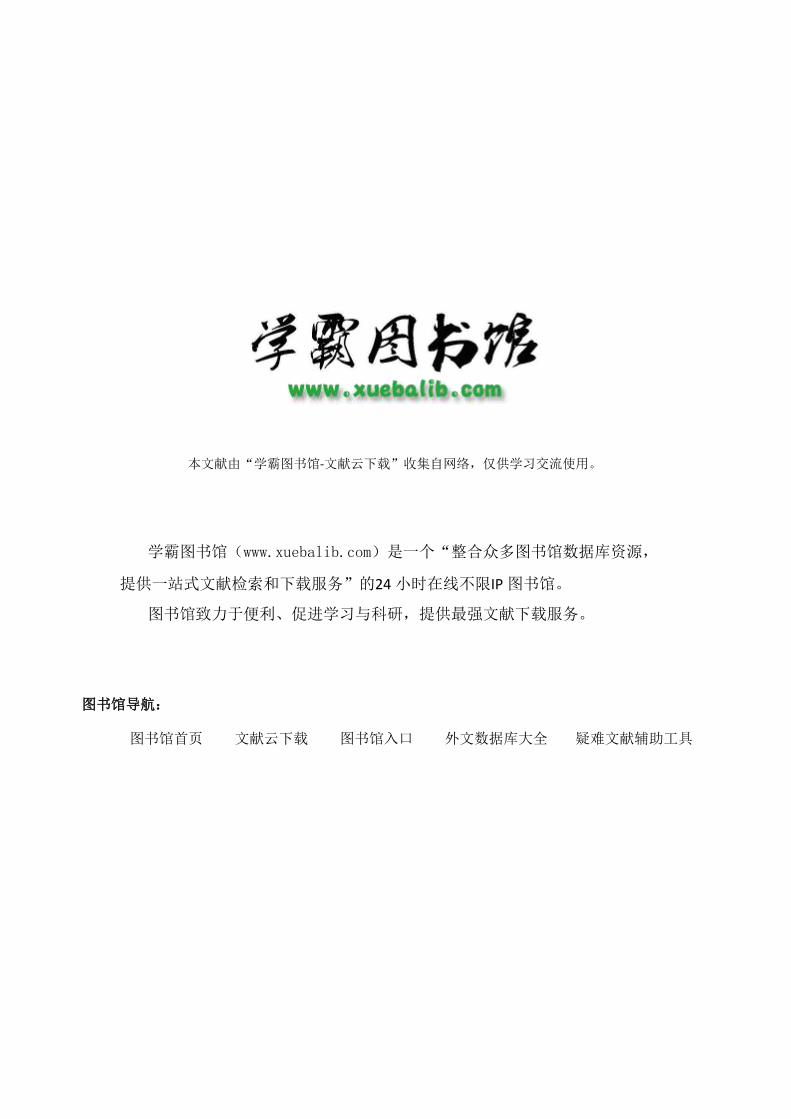
feedwater flow leads to a decrease in the length of the subcooled, nucleate boiling, and film boiling regions and an increase in the length of the superheat region. The primary and secondary heat transfer rates during the transient are shown in Fig. 19. The 80% decrease in feedwater flow resulted in an ~ 80% decrease in both heat transfer rates from 1.6281 x 10⁹ to 3.3312 x 10⁸ B.t.u./h [477.2 to 97.64 MW(t)].
5. CONCLUSIONS
A four-region dynamic model of a once-through, helical-coil steam generator with moving boundaries has been presented. The steam generator under consideration is the type used in the advanced liquid metal reactor in its superheat steam cycle design.
The model was tested for a number of transients. The results indicate that the model is capable of simulating properly the dynamic response of the steam generator for a wide range of conditions. The system transients derived from the model are useful in the design of appropriate control systems.
Once-through, helical-coil steam generator 561
xl0 ~ 1.80
1.60
i 1.40
1.20 - Feedwater -
1.00
0.80
0.60
0.40 0 200 400 600 800 1000 1200 1400 1600
Time (s) Fig. 16. Feedwater and steam flow rates during the 80% decrease in feedwater flow rate transient.
900
850
o ['h 800
750
/ #
h 700
650 [--,
I I I I I I I
/
/ /
/ /
/ t
/ 6oo /
. . . . . . . . . . . . . . . . . . . . . . . J
550 , I , I , I I , I , [ , 1 , 0 200 400 600 800 1000 1200 1400
Time (s) 1600
Fig. 17. Outgoing sodium and steam temperatures during the 80% decrease in feedwater flow rate transient.
The model can be used for flow stability studies, and it can be used also as an element in an overall system performance study of large-scale nuclear power plants.
Acknowledgements--The author acknowledges T. L. Wilson and S. J. Bali for providing valuable consultation and advice throughout this work. This research was supported in part by an appointment to the U.S. Department of Energy Laboratory Cooperative Postgraduate Research Training Program administered by the Oak Ridge Institute for Science and Education.
R E F E R E N C E S
Abdaila M. A. (1993) Report ORNL/TM 12391. Oak Ridge, Tennessee. Advanced Continuous Simulation Language (ACSL) (1991) Mitchell & Gauthier, Concord, Massachusetts. Bein M. and Yahalom R. (1975) 2nd Power Plant Dynamics, Control and Testing Symposium, Knoxville, Tennessee. Bishop A. et al. (1965) Trans. A S M E 65. Bruens N. W. S. et al. (1975) 2nd Power Plant Dynamics, Control and Testing Symposium, Knoxville, Tennessee.
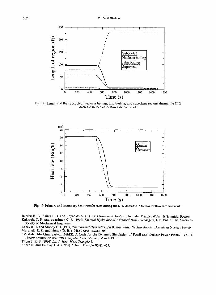
562 M . A . ABDALLA
250 I I I I I I I
/ /
2oo / /
O / Of) 15o / Subcooled
/ I Nucleate boiling I / i=qim -~o~l]n~- . . . . O 100 / .........................
! ~ Superheat
<D 50 . . . . . . . . . . . . . . . . . . . . . ,d
0 ", ........ 1 ........ ~ ........ [ ........ , ........ .!....._~'~ ---I- ---7-----]----7---- t . . . . r--- '[ . . . . , 200 400 600 800 1000 1200 1400 1600
T i m e (s) Fig. 18. Lengths of the subcooled, nucleate boiling, film boiling, and superheat regions during the 80%
decrease in feedwater flow rate transient.
©
x l 0 8
18
16
14
12
10
8
6
4
2 0
I I I I I I I
, I , I , I I , I , I , I
200 400 600 800 1000 1200 1400 1600
T i m e (s) Fig. 19. Primary and secondary heat transfer rates during the 80% decrease in feedwater flow rate transient.
Burden R. L., Faires J. D. and Reynolds A. C. (1981) Numerical Analysis, 2nd edn. Prindle, Weber & Schmidt, Boston. Kakarala C. R. and Boardman C. E. (1990) Thermal Hydraulics o f Advanced Heat Exchangers, NE. Vol. 5. The American
Society of Mechanical Engineers. Lahey R. T. and Moody F. J. (1979) The Thermal Hydraulics of a Boiling Water Nuclear Reactor. American Nuclear Society. Martinelli R. C. and Nelson D. B. (1948) Trans. ASME 70. "Modular Modeling System (MMS): A Code for the Dynamic Simulation of Fossil and Nuclear Power Plants," Vol. 1.
Theory Manual B& W/ EPRI Computer Code Manual, March 1985. Thom J. R. S. (1964) Int. J. Heat Mass Transfer 7. Zuber N. and Findlay J. A. (1965) J. Heat Transfer 87(4), 453.
本文献由“学霸图书馆-文献云下载”收集自网络,仅供学习交流使用。
学霸图书馆(www.xuebalib.com)是一个“整合众多图书馆数据库资源,
提供一站式文献检索和下载服务”的24 小时在线不限IP
图书馆。
图书馆致力于便利、促进学习与科研,提供最强文献下载服务。
图书馆导航:
图书馆首页 文献云下载 图书馆入口 外文数据库大全 疑难文献辅助工具