Embed Size (px)
Citation preview
a
Proc. of F i f t h I n t ' l Symposium on U n m a n n e d Untethered Suhwrsible Technology, June 22-24, 1987, mrrhck, New Hampshire, pp. 1-13.
A FEASIBILITY STUDY FOR A LONG RANGE AUTONOMOUS UNDERWATER VEHICLE'
M. Hebert, C.E. Thorpe,
Robotics Institute, Camegie-Melbn University,
Pmburgh, PA 15213
41 2-268-2585,
S.E. Dunn, J.M. Cushieri, Ocean Engineering Dept., Florida Atalantic University,
Boca Raton, FL 33431
P.O. Rushfeldt, W.H. Girodet,
Riviera Beach, FL 33404 Peny mshon,
P. Schweker, Westinghouse R&D, Pittsburgh, PA 15235
Abstract
Findings are presented of a study to determine the feaS&ility of devebpiw and d8monStrating a long range autonomous undemater Vehide. Based on a real war# scale program need, a technology developmenr and capability denwnstration program is described. The -ram objbdives necessary to provide a proof of princ@e imluding expected system perfomm capabilities are described together with an activw program for the d e m o ~ t i o n system. Sensor systems Aor nav@tion, obstacle avoidance, passhfe deteclrbn, veh&& motion and Whici8 health are descfib8d. Padbl;lr attention is paid to the discussion of the hadware and softwan, architecturn for the system with an e m a s i s on providing as much topdown guidance as possible and tu expbit sensor modality dflef8nCeS to produce complementary pemptual plocesses in the system. The discussion of the sotYware includes the wl icatbn of a system capable of wmttin~ parallelism in its knowlee sou~ce modules and a organized mlledion of perceptual and navQatbn modules tied together through a blackboard. The paper descrr7bes the databasa/commnkatbn system, the AUV and system bkck diaQram together with the issues which am inherent in the integmtion of dhe m&@b sensors of the system. Path planning abilities are described against a backgmund of actual sonar-&pth data obtained during the study. Simulations of a proposed vehicle, inckrdq six degms of freedm, in a marine environment are described. The evolution of the AUV system fmm simulation through conywnent testi' to the at sea demonstration is d&tssed.
'This work was supported by a grant from the Natlonal Sea Grant Office of NOAA and by the Naval Surface Weapons Center, White Oak, Maryland
.

1. Introduction . We model the organization of an AUV system by a cycle of Sensing, Thinking, and Ading. In real world . systems, this cyde goes on simultaneously at several levels. As an example, Figure 1-1 shows a
descriptive system layout: sensing up the left side, thinking across and acting down the right sue. Further, we divide the problem into three levels of abstraction: at the top, the cognitive level that does mission planning and symbolic reasoning; at the middle, a geometric level, for bcal path planning and bcal map building: and at the bottom a "reflex" level that does real time control and sensor processing.
a
Flgure 1-1: System layout
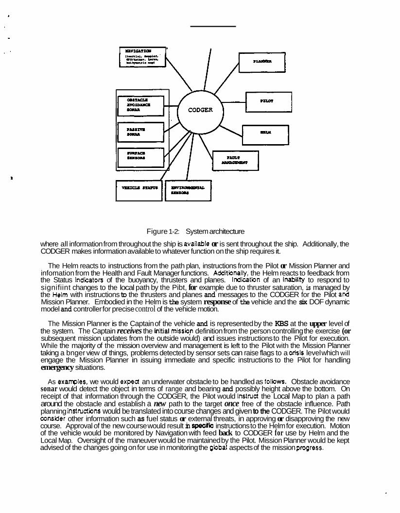
We present in this' paper a distributed architecture for an AUV based on our definition of the Sensing/Thinkirtg/Acting cycle. Figure 1-2 illustrates the functional interaction of the modules of the system.
The information fbw through the system is managed and implemented through a central module called CODGER (COmmunication Database using Geometric Reasoning). While the details of the CODGER functions are given in Section , it may be said in summary that the CODGER maintains a continuous flow and unrestricted accessibility of information for all elements of the AUV AI system requiring access to data from other elements. This is a strong point of this approach.
Sensor sets, arranged along the left hand side of the figure provide preprocessed quantitative information to the whiteboard for subsequent use by the Pibt, Helm, Fault Manager, Local M a p (including updating) and the Mission Planner (the Captain). The elements of the subsystems of each sensor set are subjected to processing at the sensor system to provide quantitative, geometric information (e.g. position, distance to an obstacle, depth, sound speed) together with the estimated certainty of the information.
The Pibt manages the item to item status of the system with special attention to how the information coming to the CODGER is representative of the system meeting its more immediate goals along the course of the mission. The Pibt functions continuously to plan the vehde's path and issue perception and control instructions. Put another way the Pilot is concerned with the "bcal path nature' of the misskn. In t e r n of an autonomous submarine, the Pibt has the "con' and the CODGER is the %ridge"
, I lpvEGlsIQy I
I
Figure 1-2: System architecture
where all information from throughout the ship is avaifable or is sent throughout the ship. Additionally, the CODGER makes information available to whatever function on the ship requires it.
The Helm reacts to instructions from the path plan, instructions from the Pilot or Mission Planner and infomation from the Health and Fault Manager functions. Addiiionally, the Helm reacts to feedback from the Status indicators of the buoyancy, thrusters and planes. Indication of an inability to respond to signifiint changes to the local path by the Pibt, for example due to thruster saturation, is managed by the Helm with instructions to the thrusters and planes and messages to the CODGER for the Pilot and Mission Planner. Embodied in the Helm is the system response of the vehicle and the six DOF dynamic model and controller for precise control of the vehicle motion.
The Mission Planner is the Captain of the vehicle and is represented by the KBS at the upper level of the system. The Captain receives the inial missiop definition from the person controlling the exercise (or subsequent mission updates from the outside would) and issues instructions to the Pilot for execution. While the majority of the mission overview and management is left to the Pilot with the Mission Planner taking a bnger view of things, problems detected by sensor sets can raise flags to a Crisis level which will engage the Mission Planner in issuing immediate and specific instructions to the Pilot for handling emergency situations.
As examples, we would expect an underwater obstacle to be handled as folbws. Obstacle avoidance sonar would detect the object in terms of range and bearing and possibly height above the bottom. On receipt of that information through the CODGER, the Pilot would instruct the Local Map to plan a path around the obstacle and establish a new path to the target once free of the obstacle influence. Path planning instnrctions would be translated into course changes and given to the CODGER. The Pilot would consider other information such as fuel status or external threats, in approving or disapproving the new course. Approval of the new course would result in speafiic instructions to the Helm for execution. Motion of the vehicle would be monitored by Navigation with feed back to CODGER for use by Helm and the Local Map. Oversight of the maneuver would be maintained by the Pilot. Mission Planner would be kept advised of the changes going on for use in monitoring the global aspects of the mission progress.
Other examples of the vehicle sensing, thinking and acting can be created. The common thread in all of this would be the interactive nature of the functions similar to the manner in which actual submarines are managed and the freedom and accessibility of information necessary to understand situations and make proper decisions.
The paper follows the division of the architecture into four sections (Figure 1-2): 1. Sensing: An AUV needs perception sensors to model the environment, as well as position and motion sensors. We d m s s the design of the Sensing part of the system in section .
2. Thinking: Section describes the main conponent of the Thinking part of the system: local planning (Pibt), and mission planning (Planner).
3. Acting: At the bottom level of the AUV control scheme lie the details of the vehicle dynamics and controls. Sectbn describes a six degree of freedom model which is the main component of the AUV.
4. Communicating: The sections of the system as well as modules within each section must be able to exchange pieces of knowledge about the environment and the mission status. We describe the design of a centralized database for real-time communication between modules in Section.
2. Sensing categories. These are:
In organizing the sensing capabiiiies required by an AUV we have divided the subject into five major
Motion and position sensing: krcrudq heading, attitude, INS, sonar logs, GPS, bathymetric
Vision sensing: Including video, laser and active sonar. ~ V i s b n processing: induding techniques to convert data from the sensors to high level
Wormation usable by the AI modules such as Pilot or Path Planner for threat recognition, ohstacie avoidance and underwater tenain based navigation.
Environmental and threat detection: Induding passive sonar (for ambient noise levels, self noise and far field threat detection and bcation), RF and microwave detection, water characteristics (temperature, salinity, sound speed, darity, etc.), magnetic anomalies, etc..
@vehicle health and power status: Vehicle system health sensors and remaining power indicators.
aids, prop turns (5,4].
Motbn sensing and vehicle navigation is a field which is mature. Advances in technology and manufacturing promise to provide more capable systems abng with more economical systems. No single approach or system will plovide the capability for an entire mission. Simulation has indicated that acceptable levels of error can be achieved using state of the art INS capabilities. In combination with AI software to best employ data from several systems, several approaches can be taken which trade off operating precision, covertness and system cost to provide a degree of performance sufficient to support an AUV system.
A visbn system for the A W must pcov#e the informatbn required to cany out four major tasks: navigation, obstacle avoidance, bottom contour following and surveillance. No single sonar system is likely to be capable of providing the scope of range, azimuth, and resolution information required. Multiple systems may offer the answer such as a combination of a phased modulation scan and fixed multiple beam sonar systems. Three dimensional imaging continues to offer opportunities for improvements as discussed by Cuschieri (21.
An additional variety of sensors for RF, microwave, communications, or video have been or can be modeled. In addiiion, a passive sonar hull array for detecting and tracking acoustic targets has been developed and verified. These models as well as models of the navigation and active sonar systems will
be incorporated into the AUV model of Figure 1-2.
a
3. Thinking In this Section, we discuss the two levels of the Thinking part of the system: high level control, and
bcal path planning.
3.1. High level control The purpose of the hqh level control module is to provide ensure that a given mission is carried by the
AUV. In addition, the module provides the capabilities for simulating the behavior of the AUV in an ocean environment test bed simulation so that the design of the system can be evaluated and can evolve easily.
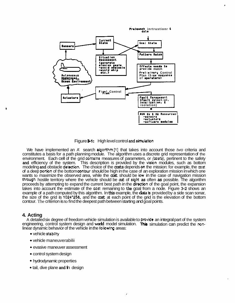
The AUV huh level control module is hierarchical with a Knowledge-Based Control (KBC) system [6] at the highest level using a control plan which matches the current state to a goal state (Fqure 3-1). When the current state does not match the goal state, operators are selected which, when applied, move the AUV cbser to the goal state. The AUVs current state is estimated from Its on-board sensors and a stored fact phase. Mission goals are baded at AUV hunch time vehicle other goals such as obstacle avoidance, ship avoidance, and fault recovery are devebped by the KBC during the mission.
The simulated AUV may use two different methods of navigation: checkpoint to checkpoint (dead redconing) using inerthl, doppler, screw turn counter and
compass- 0 m a n or bay bottom features acquired with an imaging sonar and 30 bathymetric techniques
w h i i compare water column measurements with an on-board chart of ocean or bay depths. Obstacles are avoided using returns fmm a phase comparison monophase sonar. Obstacle avoidance algorithms use a vector calculus to plan a path around the obstacle to the goal. Greater or lesser fisk of collision may be assumed by the algorithms based on the urgency to get the goal bcations.
As the AUV must be high& reliable because of its long duration missom, a faull management system has been designed which combines traditional hardware fault tolerance with an expert diagnostic system running on the fault tolerant hardware base. Both AUV hadware and software faults ate addressed.
In its present form the AUV simulator uses a hul array for detecling and localizing noise sources. The AUV simulator is used to demonstrate the capability of tradcing and following noise sources in the Chesapeake Bay. This can be changed to other problem environments. Computational requirements for the anent A W control system are such that the system can accept a six degree of freedom model for an AUV.
3.2. Local path plannlng The purpose of the path planning module is to find a good path for the vehicle, given a starting position,
a goal positinn, and a map of the environment. The goal position depends both on the mission and the current environment. The map is provided by the Sensing part of the system. The design of the path planner depends on what we mean by a good path. We identified two criteria for the m n e s s of a path:
safety: The planner must guarantee that the vehide will never be in a hazardous siluatbn when the path is executed. This implies in particular the path planner must be fast enough so that a safe path can be quickly recomputed when unexpected conditions, such as a moving threat, arise while the vehicle is executing the current path. eKiiency: A path is efiient il it maximizes some parameters dependent on the mission and the current state of the system. For example, minimizing the chances of detedion is most important when navigating in hostile territory, while maximizing the observed area is most important if we want to carry out a surveillance mission.
n
k l m u n c h i n r t r u s t i o n r 8 drt.
50.1 stat.
provido match P r r l i a i n r r y Control
nutonorour Plan (tima roqurncr Undrrrror o f oparatorr) Urhiclr in
F i n r i Control p lan ~ 1 F8Ult Nanrgorant ( f B U l t d r t r c t i o n , locmii t r t ion. L i so la t ion) -
IAUU OM L HY Rarourcar~
I - r insorr -mcturtorr -softurrr r o d u l r ~ I
Figure 3-1: High level control and simuhtbn
We have implemented an A' search aIgorithm[l] that takes into account those two criteria and constitutes a basis for a path planning module. The algorithm uses a discrete grid representation of the environment. Each cell of the grid contains measures of parameters, or (custs), pertinent to the safety and efficiency of the system. This description is provided by the vision modules, such as bottom modeling and obstacle detection. The choice of the costs depends on the mission: for example, the cost of a deep portion of the bottom contour should be high in the case of an exploration mission in which one wants to maximize the observed area, while the cost should be low in the case of navigation mission thrwgh hostile territory where the vehicle should be out of sight as often as possible. The algorithm proceeds by attempting to expand the current best path in the directkn of the goal point, the expansion takes into account the estimate of the cost remaining to the goal from a node. Figure 3-2 shows an example of a path computed by this algorithm. In this example, the data Is provided by a side scan sonar, the size of the grid is 1024'256, and the cost at each point of the grid is the elevation of the bottom contour. The criterion is to find the deepest path between starting and goal points.
4. Acting A detailed six degree of freedom vehicle simulation is available to provide an integral part of the system
engineering, control system design and world model simulation. This simulation can predict the mn- linear dynamic behavior of the vehicle in the folbwing areas:
vehicle stability vehicle maneuverabilii evasive maneuver assessment control system design
hydrodynamic properties tail, dive plane and fin design
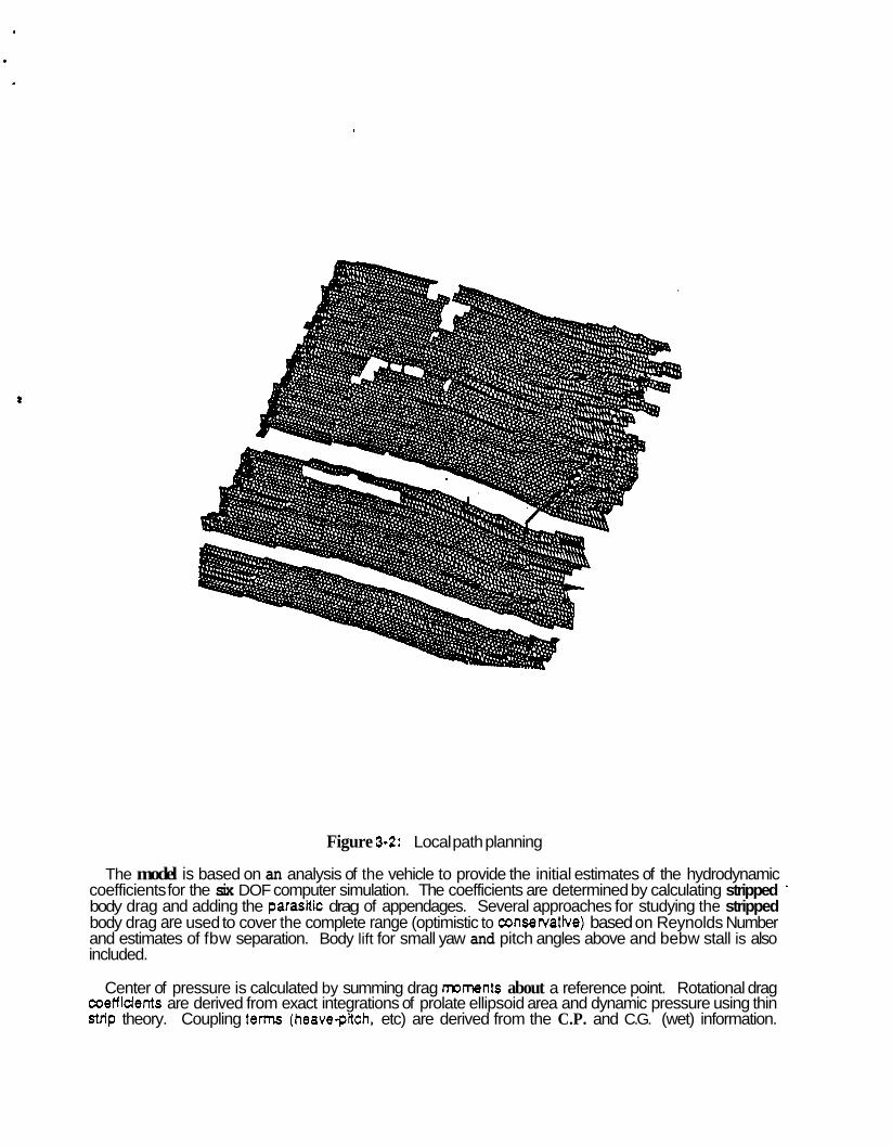
Figure 3-2: Local path planning
The model is based on an analysis of the vehicle to provide the initial estimates of the hydrodynamic coefficients for the six DOF computer simulation. The coefficients are determined by calculating stripped ' body drag and adding the parasitic drag of appendages. Several approaches for studying the stripped body drag are used to cover the complete range (optimistic to consewatbe) based on Reynolds Number and estimates of fbw separation. Body lift for small yaw and pitch angles above and bebw stall is also included.
Center of pressure is calculated by summing drag moments about a reference point. Rotational drag coefficients are derived from exact integrations of prolate ellipsoid area and dynamic pressure using thin Strip theory. Coupling terms (heave-pitch, etc) are derived from the C.P. and C.G. (wet) information.
. . m e d mass terms are derived by modeling the body as a prolate ellipsoid. Fin areas are modeled as flat plates with entrained water volumes taken as a cylinder of diameter equal to the major 'effective' fin dimension. Rotational added mass terms are derived from the parallel axis theorem. Again, it is important to state that this is a proven simulation verified against actual vehicle hardware in the water.
The vehicle control system is capable of controlling all six DOF motions. There is redundancy in pitch, roll, heave and yaw control by using either thrusters or planes. Either planes or thrusters or combinations can be used for manewering.
The philosophy is such that the Pilot decides a course and altitude to fly. The controller compares the present measured position and velocities to the desired values. Depending on gain settings, a set of desired forces and torques are computed. Since speed through water is known, the controller knows exactly how effective the planes and thrusters will be. Generally, planes are used to the maximum amount possible with thrusters being used to satisfy the remaining thrust and torque demands. The controller will not albw the thrusters to cavitate (unless ddated by an evasive maneuver) or command more thrust than is achievable. If maneuver goals cannot be met, a status message informs the pilot and goals are dropped one at a time in a predetermined manner.
The control strategy is adapive, rpkrst and relatively easy to Implement on the microprocessor based controller. The simulator can be used to evaluate the controller design and performance in liiht of the mission requirements.
With regard to the dmulatiin of an AUV in an at-sea problem environment, the simulated vehicle model can emulate the real vehicle. As such, the knowledge based amtmller can send to the vehicle simulation desired positions and vekciiies to follow. In addition, the vehicle sensor algorithms present the depth, heading, positbn, speed, pitch, roll, altitude, yaw rate, pitch rate, and mU rate. Given this information, the vehicle simulation determines thrust, exact plane position, exact positions, vebcities, accelerations and the like. These exact parameters to 7 significant digits are compted to represent the actual sensor and are fed bad< to the control system as described above.
Thus in summary, we have adopted a mature capability to design and simulate a six degree of freedom underwater vehicle as Well as build and Operate a vehicle dynaWcontrol system for the AUV. This capability is proven in actual vehicles txmr operating in the ocean.
1
5. Communicating We have up to here described the building blocks of an AUV system. The intelligence of the system
resides to a large extent in the ability to integrate these pieces into a coherent reasoning system. In this section, we describe the design principles for such an integrated system and an general implementation of a software for autonomous systems.
The main design principles are: 0Explktt repmsontatkn of geometry and time: Most of the knowledge that is shared
between modules has to do with geometry and time. .Real-tbno synchmnlzatlon: The architecture is distributed among many processes. The
system must provide for both asynchronous communications between modules, and real- time transfer of information. Vlrtual vohkb and sensors: The communication part of the system must not be concerned by the internal specifications of the sensors and the vehicle, so that the same system can be easily configurated to operate with dinerent hardware environments.
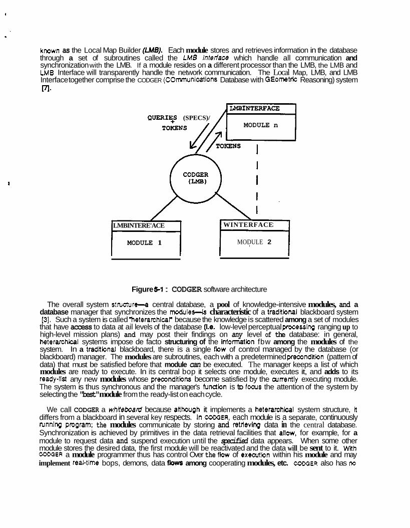
We now describe the architecture of the software for an autonomous vehicle folkwing the above principles. We originally demonstrated this software on the CMU NAVigation LABoratory (NAVLAB) [8]. The program organization of the software is shown in Fmre 5-1. Each of the major boxes represents a separately running program. The central database, called the focal Map, is managed by a program
a
known as the Local Map Builder (LMB). Each module stores and retrieves information in the database through a set of subroutines called the LMB lnrerface which handle all communication and synchronization with the LMB. If a module resides on a different processor than the LMB, the LMB and LMB Interface will transparently handle the network communication. The Local Map, LMB, and LMB Interface together comprise the CODGER (COmmunications Database with GEometric Reasoning) system m.
MODULE n QUERIE+S (SPECS)/
LMBINTERE'ACE WINTERFACE
MODULE 1 MODULE 2
Figure 5-1 : CODGER software architecture
The overall system stnrchrre-a central database, a pool of knowledge-intensive modules, and a database manager that synchronizes the m0dules-k characteristic of a tradtbnal blackboard system [3]. Such a system is called %eterarchicaF because the knowledge is scattered among a set of modules
that have access to data at ail levels of the database (Le. low-level perceptual processing ranging up to high-level mission plans) and may post their findings on any level of the database: in general, heterarchical systems impose de facto structuring of the infonatbn fbw among the modules of the system. In a traditbnal blackboard, there is a single flow of control managed by the database (or blackboard) manager. The modules are subroutines, each with a predetermined precondition (pattern of data) that must be satisfied before that module can be executed. The manager keeps a list of which modules are ready to execute. In its central bop it selects one module, executes it, and adds to its ready-list any new modules whose preconditiins become satisfied by the currently executing module. The system is thus synchronous and the manager's function is to focus the attention of the system by selecting the "best" module from the ready-list on each cycle.
We call CODGER a whiteboard because atthough it implements a heterarchical system structure, it differs from a blackboard in several key respects. In COOOER, each module is a separate, continuously running pmgram; the modules communicate by storing and retrieving data in the central database. Synchronization is achieved by primitives in the data retrieval facilities that allow, for example, for a module to request data and suspend execution until the specified data appears. When some other module stores the desired data, the first module will be reactivated and the data will be sent to it. WRh COOOER a module programmer thus has control Over the flow of executbn within his module and may implement real-time bops, demons, data flows among cooperating modules, etc. CODGER also has rto
#
precompiled list of data retrieval specifications; each time a module requests data, il provides a pattern for the data desired at that time. A whiteboard is hetearchid like a blackboard, but each module runs in parallel, with the module proglammer controllii the synchronization and data retrieval requests as best suited for each module. Like other recent distributed AI archiiecbres, whiteboards are suited to execution on multiple processors.
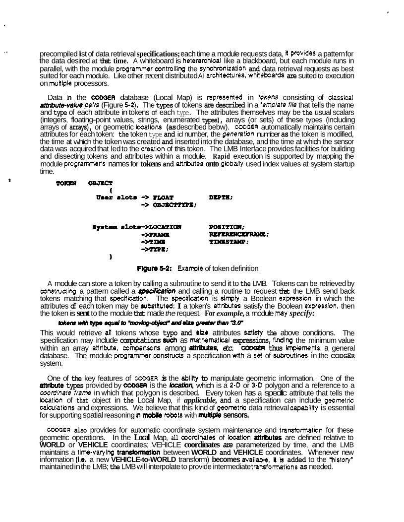
Data in the CODGER database (Local Map) is represented in tokens consisting of classical artrib~de-walue pairs (Figure 5-2). The types of tokens are described in a tenplate file that tells the name and type of each attribute in tokens of each type. The attributes themselves may be the usual scalars (integers, floating-point values, strings, enumerated types), arrays (or sets) of these types (including arrays of arrays), or geometric bcatbns (as described bebw). COMiER automatically maintains certain attributes for each token: the token type and id number, the genemtiDn number as the token is modified, the time at which the token was created and inserted into the database, and the time at which the sensor data was acquired that led to the creatbn of this token. The LMB Interface provides facilities for building and dissecting tokens and attributes within a module. Rapid execution is supported by mapping the module programrnets names for tokens and attrikrtes onto gbbally used index values at system startup time.
. .
Tom 0- (
a
Umrr m l o t m -> DIP=; -> -I;
S y m t a m l o t m - > L O C & T I W 00SITIW; ->- -; -MDQ TmST1wp; --E;
Flgure 5-2: Example of token definition 1
A module can store a token by calling a subroutine to send it to the LMB. Tokens can be retrieved by constructing a pattern called a specifkmbn and calling a routine to request that the LMB send back tokens matching that specification. The specificatbn is sinply a Boolean expression in which the attributes of each token may be substttuted; I a token's attrbtes satisfy the Boolean expressbn, then the token is sent to the module that made the request. For example, a module may specify:
This would retrieve all tokens whose typo and riU attributes satisfy the above conditions. The specification may include computations such as mathematkal expressions, finding the minimum value within an array attfiie, ampadsons among attributes, etc. CODGER thus implements a general database. The module programmer constnrds a specification wRh a cret of sukoutines in the CODGER system.
I p k . n r w i t h ~ . q u . l t O ~ urd- m u Ihu, 3.4
One of the key features of COOQER is the ability to manipulate geometric information. One of the types provided by ~OOOER is the bation, which is a 2-0 or 3-0 polygon and a reference to a
coordinate frame in which that polygon is described. Every token has a specific attribute that tells the location of that object in the Local Map, if applicable, and a specification can include geometric calarlatbns and expressions. We believe that this kind of geometric data retrieval capability is essential for supporting spatial reasoning In mobile robots with muttiple sensors.
COOaER also provides for automatic coordinate system maintenance and transformatbn for these geometric operations. In the Local Map, all ooordinates of location atMkrtes are defined relative to WORLD or VEHICLE coordinates; VEHICLE coordinates are parameterized by time, and the LMB maintains a tkne-varying transformation between WORLD and VEHICLE coordinates. Whenever new information (Le. a new VEHICLE-to-WORLD transform) becomes available, It b added to the mistory" maintained in the LMB; the LMB will interpolate to provide intermediate transformatbns as needed.
CODGER provides module synchronization through options specified for each data retrieval request. Every time a module sends a specification to the LMB to retrieve tokens, it also specifies options that tell how the LMB should respond with the matching tokens:
immediate Request. The module requests all tokens currently in the database that match this specification. The module will block (i.e. the 'request" subroutine in the LMB Interface will not return control) until the LMB has responded. If there are no tokens that match the specification, the action taken is determined by an option in the module's request:
NomBbcking. The LMB will answer that there are no matching tokens, and the module can then proceed. This would be used for timecritical modules such as vehicle control. Example: 'Is there an obstacle ?"
B/ocking. The LMB will record this specification and compare it against all incoming tokens. When a new token matches the specification, it will be sent to the module and the request will be satisfied. Meanwhile, the module will remain blocked until the LMB has responded with a token. This is the type of request used for setting up synchronized sets of communicating modules: each one waits for the resutts from the previous module to be posted to the database.
. .
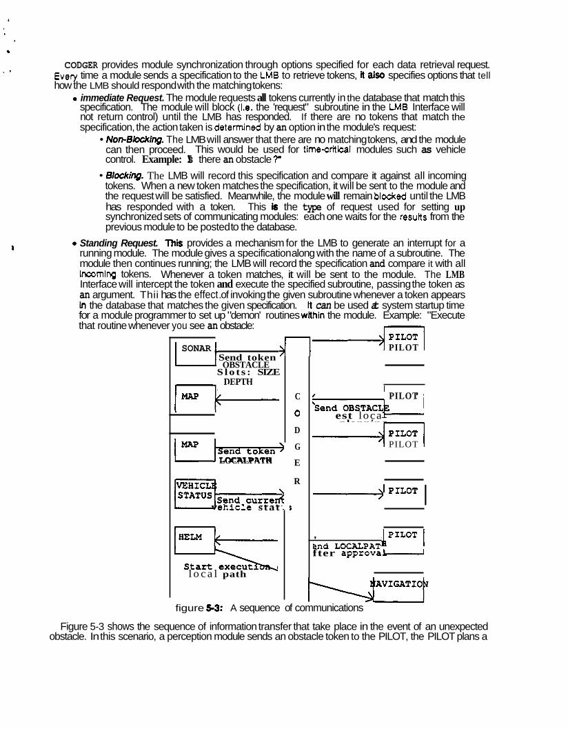
I 0 Standing Request. This provides a mechanism for the LMB to generate an interrupt for a running module. The module gives a specification along with the name of a subroutine. The module then continues running; the LMB will record the specification and compare it with all incoming tokens. Whenever a token matches, it will be sent to the module. The LMB Interface will intercept the token and execute the specified subroutine, passing the token as an argument. Thii has the effect .of invoking the given subroutine whenever a token appears In the database that matches the given specification. It can be used at system startup time for a module programmer to set up "demon' routines wlthin the module. Example: "Execute that routine whenever you see an obstacle:
I SONAR 1 Send token OBSTACLE
S lo t s : SIZE U
DEPTH - 1 - j - 3 z z m T
LOCALPATH
eh ic l e s tat
l o c a l path
C
0
D
G
E
R
J
4 PILOT
PILOT
est loca planning * PILOT
I , PILOT 1 Bnd LOCALPAT fter approva-
figure 5-3: A sequence of communications
Figure 5-3 shows the sequence of information transfer that take place in the event of an unexpected obstacle. In this scenario, a perception module sends an obstacle token to the PILOT, the PILOT plans a
path to avoid the obstacle, the path is sent eventually sent to the HELM for exeartion after its feasibility has been checked. Figure 5-3 shows only the token transfers, these tranSfefS are initiated by specifications. For example, the PILOT must initialize a standing specification in order to be interrupted in the event of an unexpected obstacle.
6. Conclusion In conclusion, we have found that it is f e a s i i to develop autonomous operatbnal capabilities in a bng
range underwater vehicle. This ability can be devebped by taking advantage of existing capabilities in AUV and ocean environmental simulation, mobile robot distributed architecture, vehicle and sensor modeling and an understanding of operating ocean environment. This capability can be added to develop a comprehensive AUV model useful for Simulating and studying the AUV question and for designing subsequent transitions from simulation to operational software and hardware in the real world. Lessons leamed and diagnostic tools produced in devebping land based autonomous vehicles were found transportable to applications in the AUV. Of special importance was the question of understanding transaction types in order to insure adequate response characteristics in the vehicle.
We found that a Systems approach was Wananted from the beginning to insure that an AUV able to function in the ocean environment and perform the range of intended functions would be produced. The interactive nature of designing the vehicle for the mission and the AI controller and the reverse problem were found to be important. MdiiionaUy we found that the transition from simulation to an at-sea demonstration exercise would best be aczomplished by first implmwnting the real time AI control code in an engineering test vehicle and refining the technology in an interactive leaming process. The type of vehicle required for this phase of the program could be designed with the simulation program described above as could Mure ~ n s t r a t i o n exercises.
a
I
9
References Cohen, P., Barr, A., Feigenbaum, E., eds. The Handbook of Artifm3l Intell~nce. William Kaufman, 1982. Cushieri, J.M. 3-0 imaging using an electronically scanned FLS. In 5th lntematonal Synposium on Unmanned Untethered Submersible T a n o m . June, 1987. E m n , L.D., Hayes-Roth, F., Lesser, V.R., Reddy, D.R. The Hearsay4 speech understanding system: integrating knowledge to resolve uncertainty. ACM Computing Surveys 12(2), June, 1980. Evans, C.D., Litton Guidance 8 Control Systems, Woodland Hills, CA. INS simulation. Private correspondence.
Patterson, W., General Electric Co. Correlation veloclty log. Private correspondence.
Schwefzer, P.F., Oravec, J.J.
Technical Report, Westinghouse RBD Center, August, 1986. Shafer, S., Stentz, A., Thorpe, C. An architecture for sensor fusion in a mobile robot. In IEEE International Conference on Robotks and Automation. 1986. Thorpe, c. Vision and navigation for the CMU Navlab. In SPE. Society of Photo-Optical Instrumentation Engineers, October, 1986.
h&//&f7f Cof7ffUl and &QM/ -8SSiw for &mmS UrderSeaS Vehide .