Embed Size (px)
Citation preview

1798
A flow reactor setup for photochemistry of biphasicgas/liquid reactionsJosef Schachtner, Patrick Bayer and Axel Jacobi von Wangelin*
Full Research Paper Open Access
Address:Institute of Organic Chemistry, University of Regensburg,Universitaetsstr. 31, 93040 Regensburg, Germany
Email:Axel Jacobi von Wangelin* - [email protected]
* Corresponding author
Keywords:biphasic reactions; flow chemistry; gas phase; microreactor; oxygen;photochemistry
Beilstein J. Org. Chem. 2016, 12, 1798–1811.doi:10.3762/bjoc.12.170
Received: 04 February 2016Accepted: 20 July 2016Published: 11 August 2016
Associate Editor: A. Kirschning
© 2016 Schachtner et al.; licensee Beilstein-Institut.License and terms: see end of document.
AbstractA home-built microreactor system for light-mediated biphasic gas/liquid reactions was assembled from simple commercial compo-
nents. This paper describes in full detail the nature and function of the required building elements, the assembly of parts, and the
tuning and interdependencies of the most important reactor and reaction parameters. Unlike many commercial thin-film and micro-
channel reactors, the described set-up operates residence times of up to 30 min which cover the typical rates of many organic reac-
tions. The tubular microreactor was successfully applied to the photooxygenation of hydrocarbons (Schenck ene reaction). Major
emphasis was laid on the realization of a constant and highly reproducible gas/liquid slug flow and the effective illumination by an
appropriate light source. The optimized set of conditions enabled the shortening of reaction times by more than 99% with equal
chemoselectivities. The modular home-made flow reactor can serve as a prototype model for the continuous operation of various
other reactions at light/liquid/gas interfaces in student, research, and industrial laboratories.
1798
IntroductionThe recent developments of microreactor technologies have sig-
nificantly impacted the art of organic synthesis and manufac-
ture [1-7]. The efficiency of chemical reactions can be greatly
enhanced over common batch processes and new approaches to
the optimization of established reaction protocols and the
execution of hitherto unfeasible processes can be enabled due to
the inherent properties of micro/flow reactors: high mass-
transfer rates [8], spatial separation of reagent addition and
mixing, high reagent dispersion, high energy efficiency, im-
proved irradiation [9-11], ease of upscaling, low hazard poten-
tial and multidimensional parameter control [7,9,11,12]. Over
the past decade, various reactor types and technical specifica-
tions have been developed to address the intricate challenges of
many chemical reactions, including the handling of hazardous
[13,14] or explosive [15,16] reagents, advanced concentration
and temperature gradients [17], multiphasic reactions including
solid-phase protocols [18], addition of gaseous reagents [19],
high-pressure conditions [20], cascade conversions without
intermediate work-up operations [21], as well as thin film,
falling film [22], micro-channel [23], and tube-in-tube reactors
Beilstein J. Org. Chem. 2016, 12, 1798–1811.
1799
Figure 1: The challenge of mixing the three dispersed entities gas, liquid, and light for photochemical applications.
[24,25] for reactions between gaseous and liquid components.
The high energy efficiency, low hazard potential, and precise
control of reaction parameters have also prompted several adop-
tions of microflow techniques in technical manufactures of fine
chemicals, polymers [26], and pharmaceutical intermediates
[27-30].
The vast majority of applications of microflow setups involved
reagents in the same aggregation state (homogeneous, mostly
liquid phase). In contrast, an especially complex problem
beyond the scope of most microreactor setups are heterogen-
eous reactions [31,32] between three dispersed entities such as a
liquid phase, a gas phase, and an electromagnetic radiation
field, where an effective interaction of three quasi mobile
phases of different physical states is required for high selectivi-
ties and conversion rates. Such scenarios are highly relevant for
photochemical reactions with reactive gases (e.g., air, O2, O3,
H2, Cl2, acetylene, NOx, CO, CO2, etc.) but obviously bear
several challenges with regard to a reproducible and precise
control of the addition and mixing of the three phases: the liquid
phase, containing organic substrates, the photo-active compo-
nent (catalyst or sensitizer), the solvent, and possibly additives,
the gas phase, containing the gaseous reagents, and the light
(Figure 1).
Only very few microreactor setups for such “quasi tri-phasic”
processes have been reported [33,34]; most of them are film/
falling film [22], microchannel [23,35] or simple tube reactors
[35-37]. The reactor reported herein differs from most of the
known systems in some key characteristics. Small-dimensioned
thin film/falling film and microchannel reactors allow resi-
dence times in the seconds-to-few-minute range, which holds
great potential for rapid conversions but is unsuitable for the
significantly slower rates of many common organic reactions.
Additionally, the gas-permeable tubes for tube-in-tube reactors
and the photo-lithographically etched [38] microchannel plates
are highly sensitive and expensive parts which limit their use by
the average organic lab chemist. For comparison, the home-
built reactor detailed in this report reliably operates at much
longer residence times (up to 30 min) and uses cheap yet robust
FEP (fluorinated ethylene propylene) tubing as transparent
reactor material. While film/falling film and microchannel reac-
tors display excellent mass-transfer and irradiation properties in
several cases [39], our reactor shows higher versatility and
tunability at a much lower price. In the following, we detail the
technical specifications, step-by-step assembly, and lab-scale
operation of an affordable, robust, and modular home-made
flow reactor which shows great promise for general applica-
tions to photochemical reactions at gas/liquid interphases.
Special attention has been paid to an especially simple reactor
set-up which is based on cheap and available materials and
parts, which can be assembled and operated with minimal tech-
nological expertise by students and researchers, yet is applic-
able to a wide range of reaction types. All parts of the modular
Beilstein J. Org. Chem. 2016, 12, 1798–1811.
1800
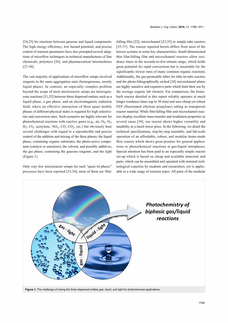
Scheme 1: Mutual interdependencies of critical reaction and reactor parameters.
reactor can be easily exchanged (capillaries, light source,
pumps, mixer, valves, etc.) and the reagents widely varied up to
2 mL min−1 liquid reagents and 50 bar inlet pressure. The
overall price of the whole system is below 10,000 €.
The wide variation of all three reaction components (liquid, gas,
light) with regard to their nature (type of substrates, solvents,
additives, gases, wavelength of light) and concentration (chemi-
cals in solution, partial pressure of gas, light intensity) was a
prime objective of this work. Furthermore, the technical param-
eters of the reaction and the reactor should be variable (temper-
ature, pressure, flow rate, residence time, and size and type of
tubing and reaction chamber). It is important to realize that
most of these parameters cannot be varied individually but are
mutually dependent on each other (e.g., choice of chromophore
vs wavelength of light vs type of (transparent) reactor walls,
concentration of reagents vs residence time for complete
conversion vs length of reactor vs flow rate, etc.). The aware-
ness of such multidimensional interdependencies is a prerequi-
site for the expedient optimization of a given chemical task by
proper choice of the general reactor setup and wide variations of
the critical reaction and reactor parameters (Scheme 1).
An efficient interaction of all three “reagents” will require
careful adjustment of the light source, the wall material, the
penetration length, the solution absorbance and other parame-
ters. Until today, such protocols under flow conditions are most
advanced with photosensitized oxidations which most recently
have matured to great efficacy and versatility by the works of
Seeberger et al. and Noël et al. Prominent examples include the
photooxidations of citronellol [35,40-42], indanes [43],
monoterpenes [36], furans [42], furfurals [44], thiols [37] and
amines [45] as well as the syntheses of ascaridol [46] and
artemisinin [47]. Related microreactor setups were applied to
biphasic gas/liquid mixtures in the photochlorination of alkyl-
benzenes [48] and [2 + 2]-cycloadditions with ethylene [49].
Results and DiscussionMicroreactor parts and setupWhen studying the numerous literature reports of applications
of flow reactors to organic synthesis it became obvious that
there are no simple and quick technical solutions to such
endeavours available to John Doe lab chemists who have no
close collaboration with engineering specialists or do not
wish to purchase sophisticated high-end devices for
>10,000 Euros.
Stimulated by the ground-breaking works of the Seeberger
[41,42,47,50,51], Booker-Milburn [52,53], and Noël [34,54,55]
groups in recent years, we therefore decided to develop our own

Beilstein J. Org. Chem. 2016, 12, 1798–1811.
1801
Scheme 2: Blueprint of the home-built microflow photoreactor; schematic illustration of the reactor setup with a) solvent reservoir, b) substrate solu-tion, c) T valve (BOLA, F 731-02), d) HPLC pump (Bischoff dosage pump 2250), e) capillary (for back-pressure build-up; Bischoff PEEK capillary1021903PK), f) oxygen supply (Linde 4.6, 200 bar), g) pressure reducing valve (GO regulator, TeamTrade, PR11I11ACW-111), h) mass flowcontroller (Brooks SLA 5850), i) T mixer (IDEX, P-727 or P-632), j) thermostat bath, k) FEP capillary, l) LED light source (24 × Cree Xlamp MK-R,warm white, 700 mA), m) back-pressure regulator (IDEX, P-763, 100 psi), n) collecting vessel.
home-made flow reactor for photooxidations of organic mole-
cules but also envisaged its general applicability to other chal-
lenging processes with the ternary “reagent” combinations
liquid/gas/light. With the objective of constructing a robust and
versatile flow reactor, we set out to explore and test commer-
cially available parts. Major emphasis was placed on maximum
flexibility with regard to reaction parameters (reagents, concen-
trations, temperature, reaction/residence time), and technical pa-
rameters (light sources, flow rates, pressure, reactor type, size
and length). The continuous operation with reproducible results
would require the use of components that ensure strictly con-
stant gas and liquid flow rates, mixing properties, irradiation
over the period of operation. In the following, we wish to
provide a hands-on manual for the design and set-up of a flow
reactor for photochemical reactions at gas/liquid interfaces in
any standard student or research laboratory. The requirements,
specifications, and pitfalls of the most critical technical compo-
nents will be discussed from the perspective of a non-expert
user (Scheme 2).
Solution pumpStandard syringe pumps generate significant pulsation so that
HPLC compact pumps are much better suited for the continu-
ous generation of a steady slug flow. However, HPLC pumps
are in direct contact with the reaction medium and thus can
experience degradation with reactive reagents/solvents. Special
attention should be directed at the homogeneity of the liquid
phase in case of, e.g., limited solubility or biphasic systems
which might require the addition of a co-solvent, prior filtration
of the solution phase, or the installation of an upstream filter. It
is important to consider that most HPLC pumps only provide
accurate and steady solution pumping when operating against a
significantly high back-pressure from the column chromatogra-
phy unit. Therefore, a very thin capillary (l = 6 m, internal
d = 0.13 mm) was placed between the pump and the reactor.
This capillary generates significant back-pressures at low flow
rates (16 bar/32 bar in acetonitrile and 27 bar/54 bar in metha-
nol at 0.5/1.0 mL min−1, respectively) and ensures a pulsation-
free operation of the pump.
Pressure reducing valve & manometerAs with the pumps, the pressure reducing valve has to ensure a
constant pressure regime during the whole span of the reaction
time. Upon careful consideration and multiple tests, we have
opted for a GO regulator prepared for oxygen usage, which
covers the targeted flow rates (up to 25 mL min−1) and pres-
sure range (52 bar maximum outlet pressure). An erratic opera-
tion of the pressure reducing valve causes pressure spikes which
prohibits a steady volume stream through the mass flow
controller.

Beilstein J. Org. Chem. 2016, 12, 1798–1811.
1802
Table 1: Molar attenuation coefficients of common photosensitizersa (bpy = 2,2‘-bipyridine).
Sensitizer Molar attenuation coefficient ε [M−1 cm−1]
rose bengal disodium salt 112,400 [56] (in ethanol)methylene blue 85,100 [57] (in acetonitrile)tetraphenylporphyrin 478,000 [58] (in chloroform)sodium fluorescein 76,000 [59] (in water, pH 7.4)[Ru(bpy)3]Cl2 14,600 [60] (in water)
aMaximum attenuation coefficients in the visible absorbance spectrum of the mentioned photosensitizers in the respective solvent.
Mass flow controllerThe mass flow controller fulfills an identical role as its liquid
phase complement, the pulsation-free pump. The precise control
of the mass flow of the gaseous reagents (here oxygen) ensures
a constant gas stream which directly correlates with the build-
up of a constant slug flow and a reproducible and constant
productivity (conversion per time interval) and thereby allows
the continuous operation of the flow reactor. Unlike the
so-called gas flow meters, mass flow controllers are active
devices that constantly measure and adjust the current volume
stream to the target value. It is especially important that the
mass flow controller is sufficiently pressure-resistant for the
specific gases and pressure range used and precisely calibrated.
As aforementioned for the HPLC pumps, thin-capillary reac-
tors can build up large back-pressures. The initial upstream
entry pressure should be set rather high in order to accommo-
date the significant pressure gradient over the capillary length.
T mixerThere are numerous types of mixers for various purposes. How-
ever, simple T-valves are suitable for most applications. A low
dead volume and a high pressure resistance are key characteris-
tics of T mixers. However, careful optimization of the internal
size, shape, and dead volume of the T-mixer directly affects the
local concentrations of the reagents and thus can have dramatic
effects on reaction rates and selectivities. Furthermore, specific
properties of the reagents and solvents (viscosity, surface
tension, gas solubility) will be critical to the dispersion and slug
flow formation.
Light sourceThe benefit of microreaction technologies applied to photo-
chemical processes is especially evident from a consideration of
the extent of light attenuation when passing through condensed
matter. The molar attenuation coefficients of common organic
photosensitizers are in the range of 20,000–500,000 M−1 cm−1
(Table 1) which significantly limits the penetration depth of
visible light into standard batch reactions at 10−4–10−2 M con-
centrations of the dye so that large volumes of the reaction
remain in the dark [9,52].
It is important to note that the magnitude of attenuation coeffi-
cients of the employed chromophores is a key difference be-
tween the recently emerging field of photocatalysis (with dyes
of ε > 10,000 M−1 cm−1) and traditional photochemistry (in-
volving mostly UV irradiation of colourless organic molecules
of ε < 1,000 M−1 cm−1) [61]. The much lower molar attenua-
tion coefficients of the majority of organic molecules which are
directly irradiated by UV light in photochemical processes (e.g.,
N-alkyl maleimides, ε = ~700 M−1 cm−1) [62] lead to more effi-
cient light penetration in batch reactions and therefore only
show a limited benefit of using flow reactors for such purposes.
On the other hand, a 1 mM solution of methylene blue exhibits
total absorption (>99.9%) at 0.35 mm penetration depth in a
solution of acetonitrile (Figure 2) [63]. The high surface-to-
volume ratio of microreactors thus increases the relative path-
way of light through the solution, speeds up the rate of reac-
tions, and minimizes competing side reactions [11,52,64,65].
Total light absorption of dye solutions with high attenuation
coefficients can be prevented by low-diameter reactor dimen-
sions and flow conditions that favour the formation of thin films
along the reactor walls.
Energy-saving light bulbs and light-emitting diodes (LEDs) of
different wavelengths (red, green, blue, white) were used for ir-
radiation of the reactions. The light source was placed in the
center of the reactor to achieve optimal irradiation [66]. Key
characteristics are the emission spectrum and the light intensity.
A perfect match of the light emission maximum and the dye’s
absorption maximum is desirable. It should also be considered
that potential excitation of other reagents could trigger competi-
tive reaction mechanisms and pathways. The LEDs were
mounted on an aluminium rod which is water-cooled from the
interior to prevent (over-)heating of the LEDs and the reaction
(Figure 3). White light was obtained from a commercial energy-
saving light bulb (Osram Dulux Superstar). LEDs exhibit high
light power (~110 lm W−1) at low energy consumption in com-
parison with other powerful light sources such as mercury
lamps (~50 lm W−1). The availability of various LED types
with different wavelengths and narrow emission spectra obvi-
ates the need for filters and allows high quantum yields by the

Beilstein J. Org. Chem. 2016, 12, 1798–1811.
1803
Figure 2: Total absorbance of methylene blue solutions in acetonitrile according to the Beer-Lambert law: Eλ = ελ·c·d. [63]. The diameter of theapplied capillary, 1/32 inch or 0.79 mm, is shown in red.
Figure 3: Red (λmax = 633 nm), blue (λmax = 448 nm), green (λmax = 520 nm) and white (λmax = 620 nm) LEDs mounted on a water cooled alumini-um cooling element.

Beilstein J. Org. Chem. 2016, 12, 1798–1811.
1804
Figure 4: Overlap of absorption spectrum of methylene blue in acetonitrile and emission spectra of reasonably overlapping light sources.
Figure 5: Emission spectra of different LEDs; red (λmax = 633 nm), blue (λmax = 448 nm), green (λmax = 520 nm), warm white (λmax = 600 nm), andOsram Dulux Superstar.
correct matching of lamp emission and chromophore absorp-
tion bands (Figure 4 and Figure 5). The absence of UV emis-
sion bands regarding the used red and warm white LEDs
enhances the selectivity of many organic reactions by suppres-
sion of unwanted UV-mediated degradation processes.
Capillary tubingWith gas-liquid two-phase flows, several flow regimes can form
which mostly depend on the configuration of the inlets, the
gravity, the size of the tube, the fluid properties, and the flow
rate. A steady and highly dispersed two-phase flow is present in
the so-called slug flow (Scheme 3, Figure 6). The resultant thin
film around the gas bubbles and along the reactor walls allows
large portions of the substrate solution to be efficiently irradi-
ated while being at the same time in contact with the gas phase.
This leads to strongly enhanced mass transfer coefficients com-
pared to traditional stirred tanks [39]. Depending on the flow
rates of gas and liquid phases, their ratio, the solvent viscosity
and the reactor dimensions, different flow pattern can be ob-
tained. The so-called slug flow leads to very efficient irradia-
Beilstein J. Org. Chem. 2016, 12, 1798–1811.
1805
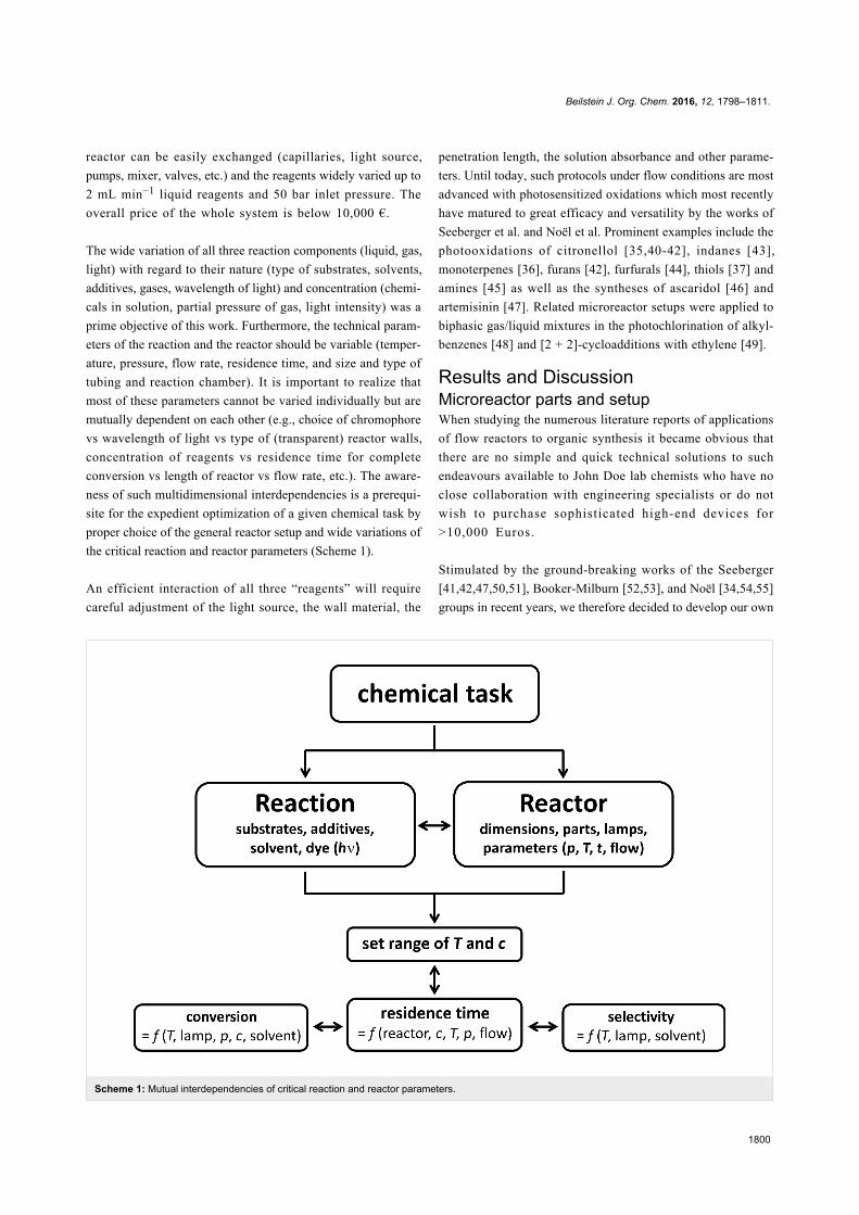
Scheme 3: Slug flow conditions of two-phase gas-liquid mixtures. Photograph of a slug flow of a solution of methylene blue (1.0 mM), a cyclohexene(0.1 M), oxygen at 30 bar, and 1.5 mL min−1 flow rate in an FEP tubing reactor (0.79 mm inner diameter).
tion but also other spatial distributions (plug flow, bubbly flow,
annular flow or isolated gas and liquid segments) can occur
under certain conditions (Scheme 3, Figure 6) [67].
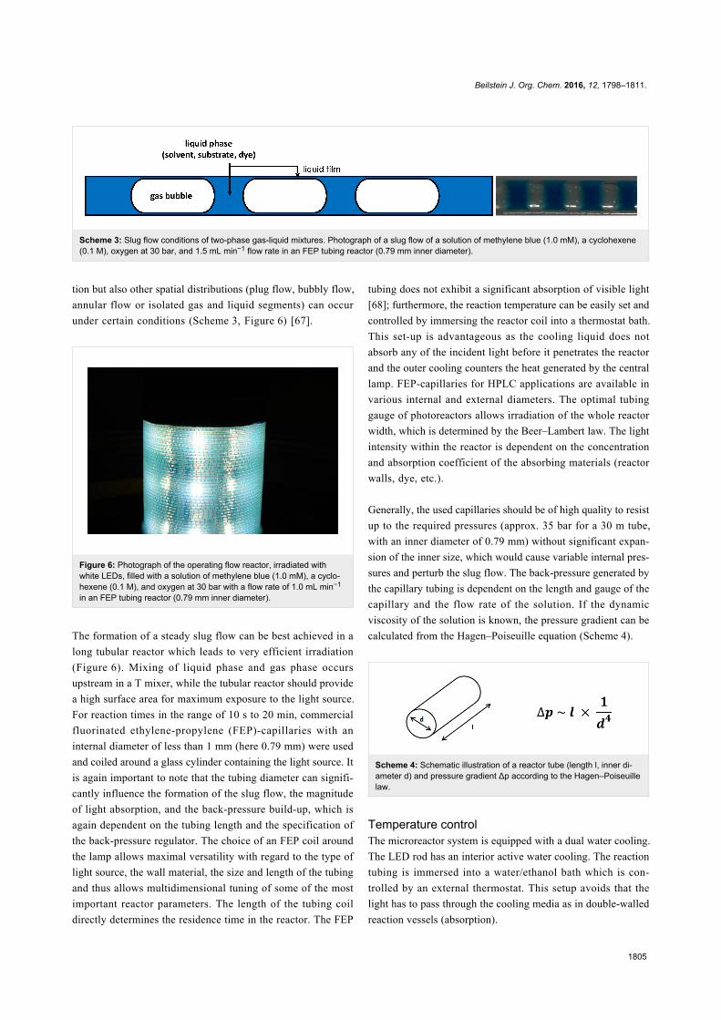
Figure 6: Photograph of the operating flow reactor, irradiated withwhite LEDs, filled with a solution of methylene blue (1.0 mM), a cyclo-hexene (0.1 M), and oxygen at 30 bar with a flow rate of 1.0 mL min−1
in an FEP tubing reactor (0.79 mm inner diameter).
The formation of a steady slug flow can be best achieved in a
long tubular reactor which leads to very efficient irradiation
(Figure 6). Mixing of liquid phase and gas phase occurs
upstream in a T mixer, while the tubular reactor should provide
a high surface area for maximum exposure to the light source.
For reaction times in the range of 10 s to 20 min, commercial
fluorinated ethylene-propylene (FEP)-capillaries with an
internal diameter of less than 1 mm (here 0.79 mm) were used
and coiled around a glass cylinder containing the light source. It
is again important to note that the tubing diameter can signifi-
cantly influence the formation of the slug flow, the magnitude
of light absorption, and the back-pressure build-up, which is
again dependent on the tubing length and the specification of
the back-pressure regulator. The choice of an FEP coil around
the lamp allows maximal versatility with regard to the type of
light source, the wall material, the size and length of the tubing
and thus allows multidimensional tuning of some of the most
important reactor parameters. The length of the tubing coil
directly determines the residence time in the reactor. The FEP
tubing does not exhibit a significant absorption of visible light
[68]; furthermore, the reaction temperature can be easily set and
controlled by immersing the reactor coil into a thermostat bath.
This set-up is advantageous as the cooling liquid does not
absorb any of the incident light before it penetrates the reactor
and the outer cooling counters the heat generated by the central
lamp. FEP-capillaries for HPLC applications are available in
various internal and external diameters. The optimal tubing
gauge of photoreactors allows irradiation of the whole reactor
width, which is determined by the Beer–Lambert law. The light
intensity within the reactor is dependent on the concentration
and absorption coefficient of the absorbing materials (reactor
walls, dye, etc.).
Generally, the used capillaries should be of high quality to resist
up to the required pressures (approx. 35 bar for a 30 m tube,
with an inner diameter of 0.79 mm) without significant expan-
sion of the inner size, which would cause variable internal pres-
sures and perturb the slug flow. The back-pressure generated by
the capillary tubing is dependent on the length and gauge of the
capillary and the flow rate of the solution. If the dynamic
viscosity of the solution is known, the pressure gradient can be
calculated from the Hagen–Poiseuille equation (Scheme 4).
Scheme 4: Schematic illustration of a reactor tube (length l, inner di-ameter d) and pressure gradient Δp according to the Hagen–Poiseuillelaw.
Temperature controlThe microreactor system is equipped with a dual water cooling.
The LED rod has an interior active water cooling. The reaction
tubing is immersed into a water/ethanol bath which is con-
trolled by an external thermostat. This setup avoids that the
light has to pass through the cooling media as in double-walled
reaction vessels (absorption).

Beilstein J. Org. Chem. 2016, 12, 1798–1811.
1806
Scheme 5: Reaction types of organic molecules with singlet oxygen.
Figure 7: Home-made flow reactor and peripheral devices for photochemical reactions at light/liquid/gas interfaces.
Back-pressure regulatorThis device fulfills many roles: It controls the pressure at the
downstream end of the reactor which should be greater than the
ambient pressure in order to avoid both, the increasing expan-
sion of the gas bubbles and the exceeding increase of the flow
rate over the length of the reactor. A sufficiently high back-
pressure secures a constant flow throughout the length of the
tubing. This set back-pressure has to be higher than the pres-
sure drop within the capillary which is especially high in long
and thin capillaries. The back-pressure regulator also controls
the solubility of the gas in the liquid phase which is pressure-
dependent according to Henry’s law [69].
Reaction parameters of a model photooxygenationThe often poor selectivities of reactions with molecular oxygen
(being a triplet biradical in its ground state) [70] have prompted
applications of microflow reactors to selective oxidations of
various organic molecules (Scheme 5). From a conceptual point
of view, the combination of two of the most abundant
“reagents” on the surface of our planet, oxygen and visible
light, with a safe, scalable, and efficient reactor technology for
chemical reactions constitutes an approach to oxidation chem-
istry of utmost sustainability. Under irradiation in the presence
of a sensitizer, singlet oxygen can easily be generated from the
triplet ground state. Several applications of such photooxida-
tions to chemical synthesis have been reported [71-73], in
recent years most effectively under microflow conditions
[41,42,50,51,74,75].
We applied the home-made photo-flow reactor (Figure 7) to the
visible light mediated oxygenation of a cyclohexene derivative
(i.e., Schenck ene reaction with singlet oxygen) [72,73] and
evaluated the critical reaction and reactor parameters. Following
an optimized Schenck ene reaction procedure, N-methyl-
1,2,3,6-tetrahydrophthalimide (1a) was reacted with molecular
oxygen in the presence of methylene blue as sensitizer

Beilstein J. Org. Chem. 2016, 12, 1798–1811.
1807
Scheme 6: Photooxygenation of N-methyl-1,2,3,6-tetrahydrophthalimide and reductive work-up to alcohol 3a.
Table 2: Conversion vs substrate concentration.a
Substrate [mol L−1] Residence time [min] Conversion [%] Productivity [µmol min−1]
0.01 5.00 75 1.90.05 5.50 70 8.80.10 6.25 75 18.80.20 6.75 80 (87b) 40.00.30 8.00 90 67.50.40 7.70 84 84.00.50 10.5 89 (95b) 111.3
aReactions at constant flow rates in acetonitrile at 10 °C; 1 mM methylene blue, 2.4 bar back-pressure, Osram Dulux Superstar. Conversions weredetermined by quantitative GC-FID vs internal standard dodecanenitrile. bConversion at identical residence time and 0.01 M substrate solution.
(Scheme 6). The resultant hydroperoxide motif (2a) constitutes
a valuable carbocyclic building block. For reasons of conve-
nience, reductive work-up with triphenylphosphine (PPh3) was
performed to obtain the stable allyl alcohol derivative 3a which
offers ample opportunities for chemical manipulations at the
alcohol, alkene, and carboxamide functions. The choice of sol-
vent is crucial as it determines the solubility of the organic sub-
strate and the dye, and the solubility as well as the lifetime of
oxygen in its singlet state (1O2) [76]. All reactions were per-
formed under irradiation with an energy-saving light bulb
(Osram Dulux Superstar) against a back-pressure of 2.4 bar
while one parameter was varied in each experiment.
It is especially important to note that reactions of non-activated
substrates which require long residence times and low flow
rates display strong interdependencies of reaction parameters
which are often negligible at higher flow rates [41,42,50,51].
While higher substrate concentrations showed only slightly
higher conversions, a significant increase of residence time at
constant flow rates was observed (Table 2). This can be attri-
buted to the increased O2 consumption at higher substrate con-
centrations and the resultant reduction of gas volume and flow
rate over the capillary length. At identical residence times, the
conversion of 1a could only be slightly improved with lower
concentrations (after 6.75 min: 80% with 0.20 M, 87% with
0.01 M). This results in an overall dramatic increase of reaction
productivity at higher substrate concentrations. In order to mini-
mize the effect of substrate concentration on the flow rates, the
internal reactor pressure must be increased which leads to a
higher O2 density, lower relative O2 consumptions, and shorter
residence times. Ongoing experiments with an inlet pressure of
35 bar do however only show insignificantly longer residence
times for higher substrate concentrations.
A similar effect on the residence time was observed by varia-
tion of the reaction temperature. Gas-phase compression at
higher temperature leads to shorter reaction times while
maximal conversion and productivity were achieved at room
temperature. A more direct relationship between conversion and
residence time resulted from variations of the concentration of
the sensitizer methylene blue (Figure 8). At >0.5 mmol L−1, a
plateau was reached (at very high dye concentrations,
>2.0 mmol L−1, 1O2 quenching leads to lower conversions)
[43,77].
Variations of the used light source regarding power and wave-
length show the importance of the conformance of the absorp-
tion spectrum of the sensitizer and the emission spectrum of the

Beilstein J. Org. Chem. 2016, 12, 1798–1811.
1808
Table 3: Residence time and conversion with different light sources.a
Light source Residence time [min] Conversion [%]
Energy-saving lamp (white) 6.25 75LED (white) 1.50 87LED (white) 3.50 >99LED (red) 3.50 80LED (red) 6.25 92LED (red) 8.00 >99
aThe reactions were performed in acetonitrile at 10 °C with concentrations of 0.1 M 1a, 1 mM methylene blue, and a back-pressure of 2.4 bar (inletpressure 10 bar). The conversions of the photooxidation were determined by quantitative GC/FID vs internal standard dodecanenitrile.
Figure 9: Reaction progress at different residence times in flow and batch reactions. Flow: reactions at different flow rates in MeCN at 10 °C; 0.01 M1a, 1 mM methylene blue, 2.4 bar, irradiation by Osram Dulux Superstar. Batch: 0.05 M 1a, 0.1 mM methylene blue in MeCN at rt, irradiation by warmwhite LEDs.
Figure 8: Conversion vs methylene blue sensitizer concentration.Reactions at constant flow rates in acetonitrile at 10 °C; 0.01 M 1a,2.4 bar, light source: Osram Dulux Superstar.
light source. Table 3 illustrates the influence of the irradiation
wavelength and intensity on the conversion at different resi-
dence times.
A direct relation between residence time and conversion is illus-
trated in Figure 9. Quantitative conversions were reached after
13.5 min; shorter residence led to lower conversion. The flow
reactor assured full conversion after several minutes for which
the batch reactions required 8 h. Furthermore, the residence
time can generally be modulated by the length of the reactor
tubing and the flow rates of solution and gas phases.
A comparison of the utilized light power of identical LEDs
which is required for complete conversion of 1 mmol substrate
in batch and flow documents that the six LEDs of the batch

Beilstein J. Org. Chem. 2016, 12, 1798–1811.
1809
Scheme 7: Oxidation of N-methyl-1,2,3,6-tetrahydro-3-acetamidophthalimide and reductive work-up to alcohol 3b.
reactions have consumed 0.56 kWh electricity within 8 h. This
equals the power of the 24 LEDs of the flow reactor
after 2 h operation which converts 9 mmol of substrate
(0.062 kWh mmol−1). An even more pronounced advantage of
the flow reactor becomes evident when using less reactive
starting materials (Scheme 7). The aminocyclohexene deriva-
tive 1b [78-81] was quantitatively converted to hydroperoxide
2b which displayed perfect trans-diastereocontrol. After 48 h in
batch mode, 3.37 kWh were consumed per mmol starting mate-
rial, which in flow mode would suffice for continuous conver-
sion of 36 mmol substrate over 12 h at 0.5 mL min−1 flow rate
(0.09 kWh mmol−1).
ConclusionThe basic technological and practical aspects of a home-made
microreactor setup for applications to photochemical processes
with gas/liquid mixtures have been described in full detail.
Special care should be taken with the design of the key compo-
nents (pumps, tubing, pressure valves) and the key parameters
(tube diameter, tube length, back pressure, flow rate) and with
their mutual interdependencies. We have presented a thorough
analysis of critical parts and conditions of a general microflow
reactor setup for photochemical reactions and an exemplary ap-
plication to oxidations with gaseous oxygen as the stoichio-
metric oxidant. The range of application of such a modular
home-built reactor is 0.04–0.5 mmol min−1 substrate through-
put, 0.4–2.5 mL min−1 liquid phase flow rates, −40 to 60 °C,
and 5–40 bar oxygen pressure. The device can be easily assem-
bled within one day from commercial parts at an overall price
of less than 1000 € for the microreactor, less than 5000 € for the
peripheral pump and mass flow controller, and less than 500 €
for each light source coil. The application of this microreactor
system to the visible light-driven photooxygenation of cyclo-
hexene derivatives documented the superiority over a standard
batch process in terms of productivity. Depending on the solu-
bility of the substrates up to 30 mmol h−1 could be oxidized.
We believe that this report provides a stepping stone for
researchers, teachers, and students around the world who wish
to enter the field of microreactor technology for organic reac-
tions at a reasonable price and effort. This detailed report on the
theoretical, technical, and chemical aspects of a non-expert ap-
plication of a home-built microreactor to a standard chemical
reaction is specifically intended to stimulate multiple reproduc-
tion.
Supporting InformationSupporting Information File 1Experimental.
[http://www.beilstein-journals.org/bjoc/content/
supplementary/1860-5397-12-170-S1.pdf]
AcknowledgementsWe gratefully acknowledge financial and intellectual support
from the Graduate School on Chemical Photocatalysis of the
German Science Foundation (DFG, GRK 1626). We thank the
group of Prof. Peter H. Seeberger (Max Planck Institute of Col-
loids and Interfaces) for stimulating discussions.
References1. Cambié, D.; Bottecchia, C.; Straathof, N. J. W.; Hessel, V.; Noël, T.
Chem. Rev. 2016. doi:10.1021/acs.chemrev.5b007072. Yoshida, J.-i. Basics of Flow Microreactor Synthesis; Springer: Japan,
2015. doi:10.1007/978-4-431-55513-13. Reschetilowski, W., Ed. Microreactors in Preparative Chemistry;
Wiley-VCH; Vol. 2013. doi:10.1002/97835276528914. Wiles, C.; Watts, P. Micro Reaction Technology in Organic Synthesis;
CRC Press, 2011.5. Hessel, V.; Hardt, S.; Löwe, H. Chemical Micro Process Engineering;
Wiley-VCH, 2004. doi:10.1002/35276030426. Ehrfeld, W.; Hessel, V.; Löwe, H. Microreactors - New Technology for
Modern Chemistry; Wiley-VCH, 2000.7. Jähnisch, K.; Hessel, V.; Löwe, H.; Baerns, M. Angew. Chem., Int. Ed.
2004, 43, 406–446. doi:10.1002/anie.2003005778. Kashid, M. N.; Renken, A.; Kiwi-Minsker, L. Chem. Eng. Sci. 2011, 66,
3876–3897. doi:10.1016/j.ces.2011.05.0159. Su, Y.; Straathof, N. J. W.; Hessel, V.; Noël, T. Chem. – Eur. J. 2014,
20, 10562–10589. doi:10.1002/chem.201400283

Beilstein J. Org. Chem. 2016, 12, 1798–1811.
1810
10. Lu, H.; Schmidt, M. A.; Jensen, K. F. Lab Chip 2001, 1, 22–28.doi:10.1039/b104037p
11. Hook, B. D. A.; Dohle, W.; Hirst, P. R.; Pickworth, M.; Berry, M. B.;Booker-Milburn, K. I. J. Org. Chem. 2005, 70, 7558–7564.doi:10.1021/jo050705p
12. Pennemann, H.; Watts, P.; Haswell, S. J.; Hessel, V.; Löwe, H.Org. Process Res. Dev. 2004, 8, 422–439. doi:10.1021/op0341770
13. Zhang, X.; Stefanick, S.; Villani, F. J. Org. Process Res. Dev. 2004, 8,455–460. doi:10.1021/op034193x
14. Nagaki, A.; Uesugi, Y.; Tomida, Y.; Yoshida, J.-i.Beilstein J. Org. Chem. 2011, 7, 1064–1069. doi:10.3762/bjoc.7.122
15. Martin, L. J.; Marzinzik, A. L.; Ley, S. V.; Baxendale, I. R. Org. Lett.2011, 13, 320–323. doi:10.1021/ol1027927
16. Vanoye, L.; Wang, J.; Pablos, M.; Philippe, R.; De Bellefon, C.;Favre-Réguillon, A. Org. Process Res. Dev. 2016, 20, 90–94.doi:10.1021/acs.oprd.5b00359
17. Yusuf, H. A.; Baldock, S. J.; Barber, R. W.; Fielden, P. R.;Goddard, N. J.; Mohr, S.; Treves Brown, B. J. Lab Chip 2009, 9,1882–1889. doi:10.1039/b823101j
18. Nikbin, N.; Watts, P. Org. Process Res. Dev. 2004, 8, 942–944.doi:10.1021/op049857x
19. de Mas, N.; Günther, A.; Schmidt, M. A.; Jensen, K. F.Ind. Eng. Chem. Res. 2003, 42, 698–710. doi:10.1021/ie020717q
20. Leclerc, A.; Alamé, M.; Schweich, D.; Pouteau, P.; Delattre, C.;de Bellefon, C. Lab Chip 2008, 8, 814–817. doi:10.1039/b717985e
21. Webb, D.; Jamison, T. F. Chem. Sci. 2010, 1, 675–680.doi:10.1039/c0sc00381f
22. Jähnisch, K.; Dingerdissen, U. Chem. Eng. Technol. 2005, 28,426–427. doi:10.1002/ceat.200407139
23. Carofiglio, T.; Donnola, P.; Maggini, M.; Rossetto, M.; Rossi, E.Adv. Synth. Catal. 2008, 350, 2815–2822.doi:10.1002/adsc.200800459
24. Brzozowski, M.; O’Brien, M.; Ley, S. V.; Polyzos, A. Acc. Chem. Res.2015, 48, 349–362. doi:10.1021/ar500359m
25. Pastre, J. C.; Browne, D. L.; O’Brien, M.; Ley, S. V.Org. Process Res. Dev. 2013, 17, 1183–1191. doi:10.1021/op400152r
26. Iwasaki, T.; Kawano, N.; Yoshida, J.-i. Org. Process Res. Dev. 2006,10, 1126–1131. doi:10.1021/op060127u
27. Bogdan, A. R.; Poe, S. L.; Kubis, D. C.; Broadwater, S. J.;McQuade, D. T. Angew. Chem., Int. Ed. 2009, 48, 8547–8550.doi:10.1002/anie.200903055
28. Gustafsson, T.; Pontén, F.; Seeberger, P. H. Chem. Commun. 2008,1100–1102. doi:10.1039/b719603b
29. Qian, Z.; Baxendale, I. R.; Ley, S. V. Synlett 2010, 505–508.doi:10.1055/s-0029-1219358
30. Porta, R.; Benaglia, M.; Puglisi, A. Org. Process Res. Dev. 2016, 20,2–25. doi:10.1021/acs.oprd.5b00325
31. Kaizuka, K.; Lee, K.-Y.; Miyamura, H.; Kobayashi, S. J. Flow Chem.2012, 2, 1–4. doi:10.1556/jfchem.2011.00014
32. Baxendale, I. R.; Deeley, J.; Griffiths-Jones, C. M.; Ley, S. V.;Saaby, S.; Tranmer, G. K. Chem. Commun. 2006, 2566–2568.doi:10.1039/b600382f
33. Gemoets, H. P. L.; Su, Y.; Shang, M.; Hessel, V.; Luque, R.; Noël, T.Chem. Soc. Rev. 2016, 45, 83–117. doi:10.1039/C5CS00447K
34. Parallel to this report, a related work has appeared: Straathof, N. J. W.;Su, Y.; Hessel, V.; Noël, T. Nat. Protoc. 2016, 11, 10–21.doi:10.1038/nprot.2015.113
35. Meyer, S.; Tietze, D.; Rau, S.; Schäfer, B.; Kreisel, G.J. Photochem. Photobiol., A: Chem. 2007, 186, 248–253.doi:10.1016/j.jphotochem.2006.08.014
36. Park, C. Y.; Kim, Y. J.; Lim, H. J.; Park, J. H.; Kim, M. J.; Seo, S. W.;Park, C. P. RSC Adv. 2015, 5, 4233–4237. doi:10.1039/C4RA12965B
37. Talla, A.; Driessen, B.; Straathof, N. J. W.; Milroy, L.-G.; Brunsveld, L.;Hessel, V.; Noël, T. Adv. Synth. Catal. 2015, 357, 2180–2186.doi:10.1002/adsc.201401010
38. Hibara, A.; Iwayama, S.; Matsuoka, S.; Ueno, M.; Kikutani, Y.;Tokeshi, M.; Kitamori, T. Anal. Chem. 2005, 77, 943–947.doi:10.1021/ac0490088
39. Nieves-Remacha, M. J.; Kulkarni, A. A.; Jensen, K. F.Ind. Eng. Chem. Res. 2013, 52, 8996–9010. doi:10.1021/ie4011707
40. Noël, T.; Hessel, V. ChemSusChem 2013, 6, 405–407.doi:10.1002/cssc.201200913
41. Gilmore, K.; Seeberger, P. H. Chem. Rec. 2014, 14, 410–418.doi:10.1002/tcr.201402035
42. Lévesque, F.; Seeberger, P. H. Org. Lett. 2011, 13, 5008–5011.doi:10.1021/ol2017643
43. Nagasawa, Y.; Tanba, K.; Tada, N.; Yamaguchi, E.; Itoh, A. Synlett2015, 26, 412–415. doi:10.1055/s-0034-1379698
44. Heugebaert, T. S. A.; Stevens, C. V.; Kappe, C. O. ChemSusChem2015, 8, 1648–1651. doi:10.1002/cssc.201403182
45. Ushakov, D. B.; Gilmore, K.; Kopetzki, D.; McQuade, D. T.;Seeberger, P. H. Angew. Chem., Int. Ed. 2014, 53, 557–561.doi:10.1002/anie.201307778
46. Wootton, R. C. R.; Fortt, R.; de Mello, A. J. Org. Process Res. Dev.2002, 6, 187–189. doi:10.1021/op0155155
47. Lévesque, F.; Seeberger, P. H. Angew. Chem., Int. Ed. 2012, 51,1706–1709. doi:10.1002/anie.201107446
48. Ehrich, H.; Linke, D.; Morgenschweis, K.; Baerns, M.; Jähnisch, K.Chimia 2002, 56, 647–653.
49. Terao, K.; Nishiyama, Y.; Tanimoto, H.; Oelgemöller, M.; Morimoto, T.J. Flow Chem. 2012, 2, 73–76. doi:10.1556/JFC-D-12-00005
50. Ushakov, D. B.; Plutschack, M. B.; Gilmore, K.; Seeberger, P. H.Chem. – Eur. J. 2015, 21, 6528–6534. doi:10.1002/chem.201500121
51. Plutschack, M. B.; Correia, C. A.; Seeberger, P. H.; Gilmore, K.Organic Photoredox Chemistry in Flow. In Organometallic FlowChemistry; Topics in Organometallic Chemistry; Noël, T., Ed.; SpringerInternational Publishing: Switzerland, 2015; Vol. 57, pp 43–76.doi:10.1007/3418_2015_155
52. Knowles, J. P.; Elliott, L. D.; Booker-Milburn, K. I.Beilstein J. Org. Chem. 2012, 8, 2025–2052. doi:10.3762/bjoc.8.229
53. Blackham, E. E.; Knowles, J. P.; Burgess, J.; Booker-Milburn, K. I.Chem. Sci. 2016, 7, 2302–2307. doi:10.1039/C5SC04062K
54. Borukhova, S.; Noël, T.; Hessel, V. ChemSusChem 2016, 9, 67–74.doi:10.1002/cssc.201501367
55. Gemoets, H. P. L.; Hessel, V.; Noël, T. Org. Lett. 2014, 16, 5800–5803.doi:10.1021/ol502910e
56. Linden, S. M.; Neckers, D. C. Photochem. Photobiol. 1988, 47,543–550. doi:10.1111/j.1751-1097.1988.tb08842.x
57. Measured on an Agilent Varian Cary® 50 UV-Vis spectrophotometer;attenuation coefficient at an absorbance maximum of λmax = 655 nm.
58. Stone, A.; Fleischer, E. B. J. Am. Chem. Soc. 1968, 90, 2735–2748.doi:10.1021/ja01013a001
59. Mota, M. C.; Carvalho, P.; Ramalho, J.; Leite, E. Int. Ophthalmol. 1991,15, 321–326. doi:10.1007/BF00128951
60. Kalyanasundaram, K. Coord. Chem. Rev. 1982, 46, 159–244.doi:10.1016/0010-8545(82)85003-0
61. Elliott, L. D.; Knowles, J. P.; Koovits, P. J.; Maskill, K. G.; Ralph, M. J.;Lejeune, G.; Edwards, L. J.; Robinson, R. I.; Clemens, I. R.; Cox, B.;Pascoe, D. D.; Koch, G.; Eberle, M.; Berry, M. B.; Booker-Milburn, K. I.Chem. – Eur. J. 2014, 20, 15226–15232. doi:10.1002/chem.201404347
Beilstein J. Org. Chem. 2016, 12, 1798–1811.
1811
62. Hoyle, C. E.; Clark, S. C.; Jonsson, S.; Shimose, M. Polymer 1997, 38,5695–5697. doi:10.1016/S0032-3861(97)00181-X
63. Swinehart, D. F. J. Chem. Educ. 1962, 39, 333–335.doi:10.1021/ed039p333
64. Bourne, S. L.; Ley, S. V. Adv. Synth. Catal. 2013, 355, 1905–1910.doi:10.1002/adsc.201300278
65. Coyle, E. E.; Oelgemöller, M. Photochem. Photobiol. Sci. 2008, 7,1313–1322. doi:10.1039/b808778d
66. Fischer, M. Angew. Chem., Int. Ed. Engl. 1978, 17, 16–26.doi:10.1002/anie.197800161
67. Yavorskyy, A.; Shvydkiv, O.; Limburg, C.; Nolan, K.; Delauré, Y. M. C.;Oelgemöller, M. Green Chem. 2012, 14, 888–892.doi:10.1039/c2gc16439f
68. Galante, A. M. S.; Galante, O. L.; Campos, L. L.Nucl. Instrum. Methods Phys. Res., Sect. A 2010, 619, 177–180.doi:10.1016/j.nima.2009.10.103
69. Sander, R. Atmos. Chem. Phys. 2015, 15, 4399–4981.doi:10.5194/acp-15-4399-2015
70. Jori, G.; Trotta, M., Eds. Singlet Oxygen : Application in Biosciencesand Nanosciences; Royal Society of Chemistry, 2016.doi:10.1039/9781782626992-FP001
71. Esser, P.; Pohlmann, B.; Scharf, H.-D. Angew. Chem., Int. Ed. Engl.1994, 33, 2009–2023. doi:10.1002/anie.199420091
72. Alberti, M.; Orfanopoulos, M. Synlett 2010, 2010, 999–1026.73. Prein, M.; Adam, W. Angew. Chem., Int. Ed. Engl. 1996, 35, 477–494.
doi:10.1002/anie.19960477174. Ogilby, P. R. Chem. Soc. Rev. 2010, 39, 3181–3209.
doi:10.1039/b926014p75. Mimoun, H. Angew. Chem., Int. Ed. Engl. 1982, 21, 734–750.
doi:10.1002/anie.19820734176. Jenny, T. A.; Turro, N. J. Tetrahedron Lett. 1982, 23, 2923–2926.
doi:10.1016/S0040-4039(00)87495-X77. Gollnick, K.; Griesbeck, A. Tetrahedron 1984, 40, 3235–3250.
doi:10.1016/0040-4020(84)85006-178. Klaus, S.; Hübner, S.; Neumann, H.; Strübing, D.;
Jacobi von Wangelin, A.; Gördes, D.; Beller, M. Adv. Synth. Catal.2004, 346, 970–978. doi:10.1002/adsc.200404056
79. Neumann, H.; Jacobi von Wangelin, A.; Gördes, D.; Spannenberg, A.;Beller, M. J. Am. Chem. Soc. 2001, 123, 8398–8399.doi:10.1021/ja010503k
80. Jacobi von Wangelin, A.; Neumann, H.; Gördes, D.; Spannenberg, A.;Beller, M. Org. Lett. 2001, 3, 2895–2898. doi:10.1021/ol0101436
81. Neumann, H.; Jacobi von Wangelin, A.; Goerdes, D.; Spannenberg, A.;Baumann, W.; Beller, M. Tetrahedron 2002, 58, 2381–2387.doi:10.1016/S0040-4020(02)00116-3
License and TermsThis is an Open Access article under the terms of the
Creative Commons Attribution License
(http://creativecommons.org/licenses/by/2.0), which
permits unrestricted use, distribution, and reproduction in
any medium, provided the original work is properly cited.
The license is subject to the Beilstein Journal of Organic
Chemistry terms and conditions:
(http://www.beilstein-journals.org/bjoc)
The definitive version of this article is the electronic one
which can be found at:
doi:10.3762/bjoc.12.170