Embed Size (px)
Citation preview
A FINITE ELEMENT APPROACH FOR THE DESIGN OF INNOVATIVE ABLATIVE
MATERIALS FOR SPACE APPLICATIONS
Valerio Carandente (1)
, Roberto Scigliano (2)
, Valeria De Simone (3)
, Antonio Del Vecchio (4)
, Roberto Gardi (5)
(1) Italian Aerospace Research Centre (CIRA), Via Maiorise snc, 81043 Capua, Italy, Email: [email protected]
(2) Italian Aerospace Research Centre (CIRA), Via Maiorise snc, 81043 Capua, Italy, Email: [email protected]
(3) Italian Aerospace Research Centre (CIRA), Via Maiorise snc, 81043 Capua, Italy, Email: [email protected]
(4) Italian Aerospace Research Centre (CIRA), Via Maiorise snc, 81043 Capua, Italy, Email: [email protected]
(5) Italian Aerospace Research Centre (CIRA), Via Maiorise snc, 81043 Capua, Italy, Email: [email protected]
ABSTRACT
The flow field around hypersonic vehicles requires a
properly designed Thermal Protection System for the
vehicle survival. Generally these systems rely on
carbon-based composites, which possess the best
compromise among thermal, thermo-chemical and
mechanical properties. For particularly stressing re-
entry conditions (e.g. for super-orbital velocities) the
material surface recession, known as ablation, can arise.
The physicochemical phenomena connected with the
material ablation are globally endothermic and can be
exploited to reduce the heat flux entering the internal
structure.
The objective of the present work is to present a
numerical procedure developed on the basis of the
ANSYS Parametric Design Language to simulate the
ablation process and the temperature distribution inside
materials subjected to severe heat flux conditions with a
Finite Element approach. Such model also provides a
tool for the design of experimental tests in Plasma Wind
Tunnel facilities.
The preliminary numerical results are validated by
means of a cross-checking against numerical and
experimental test cases reported in literature. Then the
statistical Design Of Experiments technique is applied
to verify the influence of some inputs on the main
ablation parameters.
1. INTRODUCTION
The evaluation of the Thermal Protection System (TPS)
response for any atmospheric entry vehicle is of utmost
importance for its correct dimensioning and
effectiveness.
If the TPS is made of an ablative material, in particular,
the thermal response calculation has to take into account
a wide number of physico-chemical phenomena
connected with the fluid-material interaction in high
enthalpy hypersonic conditions. In that case, in fact, a
non-negligible part of the hypersonic heat flux can be
absorbed by the material through a number of
endothermic processes, able to cause the material
recession. In particular, the material surface directly
exposed to the hypersonic flux is subjected to charring,
melting and sublimation phenomena, while the material
bulk to pyrolysis. The gaseous residual of all these
Figure 1. Schematic of the main phenomena involved in
ablation process [1]
reactions blows in the boundary layer, also passing
through the material porosity, as shown in Fig. 1.
Historically, many classes of ablative materials have
been successfully employed as thermal protection
materials of hypersonic re-entry vehicle. In particular
they have been employed on many orbital and super-
orbital capsules (e.g. Viking, Apollo, ARD, Mars
Pathfinder and so on).
The most common ablative materials are [1]:
• SLA-516V
• PICA
• SIRCA
• AVCOAT
The Super Lightweight Ablator (SLA) has been realized
by Lockheed Martin and employed in all the Mars
missions, starting with Viking up to the Mars
Exploration Rover (MER) [1].
The material ablation starts to be significant for heat
fluxes in the order of 1 MW/m2, while the upper
boundary is around 3 MW/m2.
The Phenolic Impregnated Carbon Ablator (PICA) has
been developed at NASA-Ames since 90 s. It has been
employed for the first time for the capsule Stardust and
is currently the baseline forebody TPS for the Orion
Crew Exploration Vehicle (CEV). For Stardust capsule,
the PICA TPS was fabricated as one piece. For larger
vehicles this technique would not be applicable, leading
to a tiled design with significant design and fabrication
complexities.
PICA is a low-density carbon-based ablator with an
extensive database, mainly developed for the Orion
CEV program. A huge test campaign has also clearly
shown the boundary flow conditions for the material,
i.e. a maximum heat flux of 15 MW/m2 and a maximum
pressure in the order of 1-1.5 atm [1].
SIRCA has been developed at NASA-Ames for the X-
34 re-entry vehicle, which has never been tested in
flight. Nonetheless it has been selected for the
backshells of Mars Pathfinder and MER vehicles [1].
AVCOAT has been produced by Textron and
successfully employed in 60 s for the TPS of Apollo
capsules. More recently, it has been also selected as
backup solution for the heatshield of the Orion CEV
capsule [1].
The main thermo-mechanical properties of such
materials can be found in [2], while for PICA materials
also more detailed studies, also including experimental
test results in high enthalpy conditions, are available in
literature [3]. This is the main reason why in the present
phase of the study the PICA properties have been
implemented in the numerical model described in the
following. In this way, the model has been also
validated crosschecking numerical results with
analogous experimental and numerical tests reported in
literature [4].
2. NUMERICAL MODEL
In the present work thermal analyses on PICA ablative
materials have been performed on the basis of a Finite
Element Method implemented in ANSYS. The ANSYS
Parametric Design Language (APDL) has been also
employed to take into account the most significant
phenomena connected with the material ablation and
with the temperature dependent heat flux conditions.
Phenolic Impregnated Carbon Ablators (PICA) are
light-weight ablators composed of a fibrous carbon
Fiberform® impregnated in a two-component phenolic
resin, whose thermal properties (i.e. the thermal
conductivity, the specific heat and the effective heat of
ablation) have been widely investigated in recent years
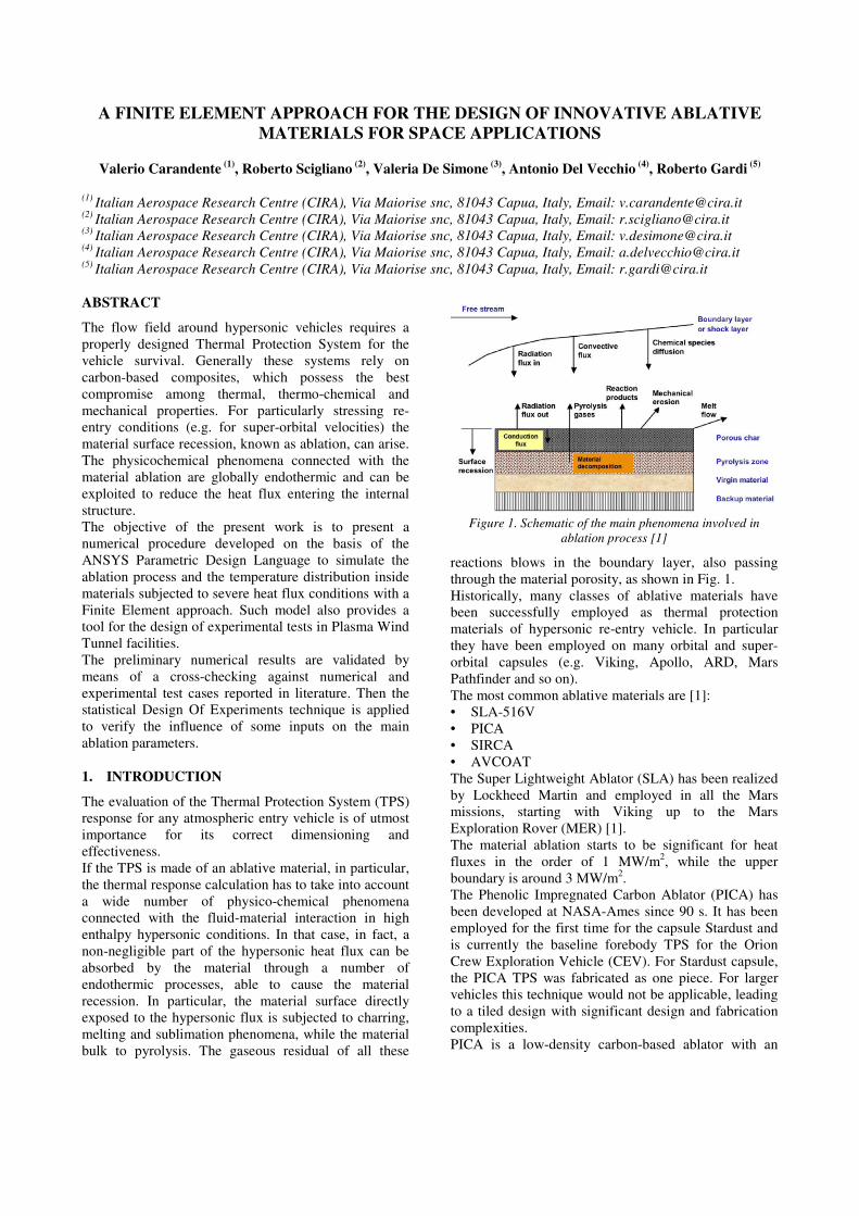
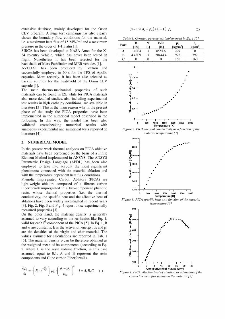
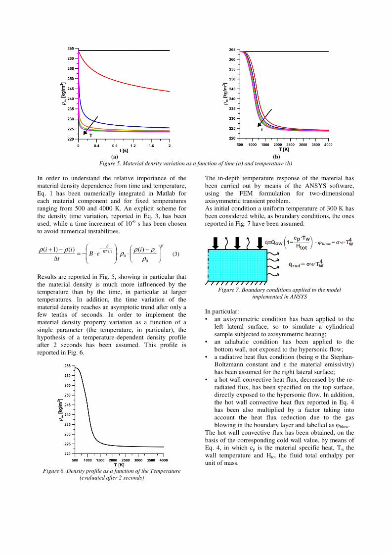
[3]. Fig. 2, Fig. 3 and Fig. 4 report those experimentally
measured properties [3].
On the other hand, the material density is generally
assumed to vary according to the Arrhenius-like Eq. 1,
valid for each ith
component of the PICA [5]. In Eq. 1, B
and ψ are constants, E is the activation energy, ρ0 and ρc
are the densities of the virgin and char material. The
values assumed for calculations are reported in Tab. 1
[5]. The material density ρ can be therefore obtained as
the weighted mean of its components (according to Eq.
2, where Γ is the resin volume fraction, in this case
assumed equal to 0.1, A and B represent the resin
components and C the carbon Fiberform®).
CBAieBt
ii
i
ciii
RT
E
ii ,,
0
0 =
−⋅⋅
⋅−=
∂
∂ −ψ
ρ
ρρρ
ρ (1)
( ) ( ) CBA ρρρρ ⋅Γ−++⋅Γ= 1 (2)
Table 1. Constant parameters implemented in Eq. 1 [5]
Part B
[1/s]
Ψ
[-]
E/R
[K]
ρ0
[kg/m3]
ρc
[kg/m3]
A 1.40E4 3 8555.6 229 0
B 4.48E9 3 20444.4 972 792
C 0 0 0 160 160
Figure 2. PICA thermal conductivity as a function of the
material temperature [3]
Figure 3: PICA specific heat as a function of the material
temperature [3]
Figure 4. PICA effective heat of ablation as a function of the
convective heat flux acting on the material [3]
(a) (b)
Figure 5. Material density variation as a function of time (a) and temperature (b)
In order to understand the relative importance of the
material density dependence from time and temperature,
Eq. 1 has been numerically integrated in Matlab for
each material component and for fixed temperatures
ranging from 500 and 4000 K. An explicit scheme for
the density time variation, reported in Eq. 3, has been
used, while a time increment of 10-6
s has been chosen
to avoid numerical instabilities.
ψ
ρ
ρρρ
ρρ
−⋅⋅
⋅−=
∆
−+ −
0
0
)( )()()1( ciRT
E
ieB
t
ii (3)
Results are reported in Fig. 5, showing in particular that
the material density is much more influenced by the
temperature than by the time, in particular at larger
temperatures. In addition, the time variation of the
material density reaches an asymptotic trend after only a
few tenths of seconds. In order to implement the
material density property variation as a function of a
single parameter (the temperature, in particular), the
hypothesis of a temperature-dependent density profile
after 2 seconds has been assumed. This profile is
reported in Fig. 6.
Figure 6. Density profile as a function of the Temperature
(evaluated after 2 seconds)
The in-depth temperature response of the material has
been carried out by means of the ANSYS software,
using the FEM formulation for two-dimensional
axisymmetric transient problem.
As initial condition a uniform temperature of 300 K has
been considered while, as boundary conditions, the ones
reported in Fig. 7 have been assumed.
Figure 7. Boundary conditions applied to the model
implemented in ANSYS
In particular:
• an axisymmetric condition has been applied to the
left lateral surface, so to simulate a cylindrical
sample subjected to axisymmetric heating;
• an adiabatic condition has been applied to the
bottom wall, not exposed to the hypersonic flow;
• a radiative heat flux condition (being σ the Stephan-
Boltzmann constant and ε the material emissivity)
has been assumed for the right lateral surface;
• a hot wall convective heat flux, decreased by the re-
radiated flux, has been specified on the top surface,
directly exposed to the hypersonic flow. In addition,
the hot wall convective heat flux reported in Eq. 4
has been also multiplied by a factor taking into
account the heat flux reduction due to the gas
blowing in the boundary layer and labelled as φblow.
The hot wall convective flux has been obtained, on the
basis of the corresponding cold wall value, by means of
Eq. 4, in which cp is the material specific heat, Tw the
wall temperature and Htot the fluid total enthalpy per
unit of mass.
⋅−⋅=
tot
wp
cwhwH
TcQQ 1&& (4)
As far as the material recession is concerned, the
assumption of steady-state ablation has been considered.
At each instant of time the ablation rate s& has been
estimated by Eq. 5 [6], in which Q* is the heat of
ablation also plotted in Fig. 4 for PICA.
*Q
Qs hw
⋅=
ρ
&
& (5)
After the estimation of the material recession rate, at
each (i+1)th
time step, the material thickness has been
predicted decreasing the material thickness at the ith
time step by the receded material in the time laps dt, as
reported in Eq. 6.
dtsisis ⋅−=+ &)()1( (6)
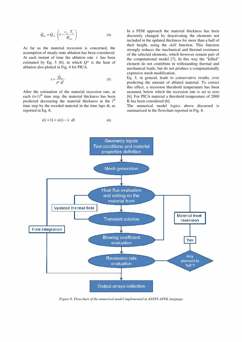
In a FEM approach the material thickness has been
discretely changed by deactivating the elements not
included in the updated thickness for more than a half of
their height, using the ekill function. This function
strongly reduces the mechanical and thermal resistance
of the selected elements, which however remain part of
the computational model [7]. In this way the “killed”
element do not contribute in withstanding thermal and
mechanical loads, but do not produce a computationally
expensive mesh modification.
Eq. 5, in general, leads to conservative results, over
predicting the amount of ablated material. To correct
this effect, a recession threshold temperature has been
assumed, below which the recession rate is set to zero
[6]. For PICA material a threshold temperature of 2000
K has been considered [6].
The numerical model logics above discussed is
summarized in the flowchart reported in Fig. 8.
Figure 8. Flowchart of the numerical model implemented in ANSYS APDL language
3. VERIFICATION AND VALIDATION OF
COMPUTATIONAL RESULTS
In the present paragraph a convergence analysis for the
numerical model described in previous section has been
performed. In addition, the model has been also
validated crosschecking numerical results with
analogous outcomes of experimental and numerical tests
reported in literature [4].
Numerical analyses have been carried out in accordance
with the assumptions made in [4], so to have a direct
comparison, assuming a time step of 0.01 s. Reference
test conditions are reported in Tab. 2, where tmax is the
transient analysis duration. In addition, for the
cylindrical material sample a radius of 5.08 cm and an
initial height of 2.74 cm have been assumed. Finally, a
material emissivity of 0.9 has been considered for the
evaluation of the re-radiated heat flux.
Table 2. Test condition for model verification and validation
cwQ&
[MW/m2] p [atm]
Htot
[MJ/kg] tmax [s]
5.80 0.450 29.5 15
3.1. Convergence analysis
In this subsection a convergence analysis is reported and
described. The computational mesh has been realized
using a growing number of elements in radial and axial
directions, according to values reported in Tab. 3.
Table 3. Number of elements in radial and axial directions for
the different analyzed cases
Number of elements Case # Axial direction (n) Radial direction (m)
1 10 20 2 25 45 3 50 95 4 75 135 5 100 185
The first comparison has been carried out on the basis of
the computed thickness, both integrating Eq. 5
(continuous variation) and multiplying the number of
the “alive” elements by their height dy (discrete
variation). Fig. 9 through Fig. 13 report the comparison
between the continuous and the discrete thickness
variation for the different analyzed cases. Fig. 14 shows
the error between the final thickness estimated by means
of the discrete approach for the different analyzed cases
and the final thickness evaluated for n=100 with the
continuous approach.
Figure 9. Comparison between continuous and discrete
thickness variation for n=10
Figure 10. Comparison between continuous and discrete
thickness variation for n=25
Figure 11. Comparison between continuous and discrete
thickness variation for n=50
Figure 12. Comparison between continuous and discrete
thickness variation for n=75
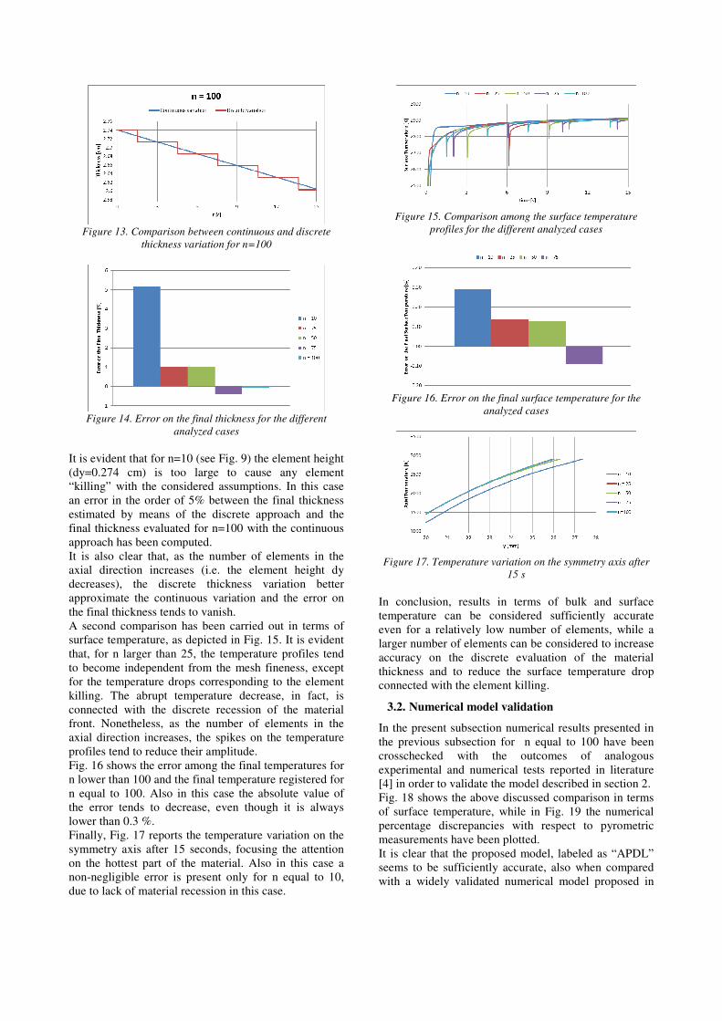
Figure 13. Comparison between continuous and discrete
thickness variation for n=100
Figure 14. Error on the final thickness for the different
analyzed cases
It is evident that for n=10 (see Fig. 9) the element height
(dy=0.274 cm) is too large to cause any element
“killing” with the considered assumptions. In this case
an error in the order of 5% between the final thickness
estimated by means of the discrete approach and the
final thickness evaluated for n=100 with the continuous
approach has been computed.
It is also clear that, as the number of elements in the
axial direction increases (i.e. the element height dy
decreases), the discrete thickness variation better
approximate the continuous variation and the error on
the final thickness tends to vanish.
A second comparison has been carried out in terms of
surface temperature, as depicted in Fig. 15. It is evident
that, for n larger than 25, the temperature profiles tend
to become independent from the mesh fineness, except
for the temperature drops corresponding to the element
killing. The abrupt temperature decrease, in fact, is
connected with the discrete recession of the material
front. Nonetheless, as the number of elements in the
axial direction increases, the spikes on the temperature
profiles tend to reduce their amplitude.
Fig. 16 shows the error among the final temperatures for
n lower than 100 and the final temperature registered for
n equal to 100. Also in this case the absolute value of
the error tends to decrease, even though it is always
lower than 0.3 %.
Finally, Fig. 17 reports the temperature variation on the
symmetry axis after 15 seconds, focusing the attention
on the hottest part of the material. Also in this case a
non-negligible error is present only for n equal to 10,
due to lack of material recession in this case.
Figure 15. Comparison among the surface temperature
profiles for the different analyzed cases
Figure 16. Error on the final surface temperature for the
analyzed cases
Figure 17. Temperature variation on the symmetry axis after
15 s
In conclusion, results in terms of bulk and surface
temperature can be considered sufficiently accurate
even for a relatively low number of elements, while a
larger number of elements can be considered to increase
accuracy on the discrete evaluation of the material
thickness and to reduce the surface temperature drop
connected with the element killing.
3.2. Numerical model validation
In the present subsection numerical results presented in
the previous subsection for n equal to 100 have been
crosschecked with the outcomes of analogous
experimental and numerical tests reported in literature
[4] in order to validate the model described in section 2.
Fig. 18 shows the above discussed comparison in terms
of surface temperature, while in Fig. 19 the numerical
percentage discrepancies with respect to pyrometric
measurements have been plotted.
It is clear that the proposed model, labeled as “APDL”
seems to be sufficiently accurate, also when compared
with a widely validated numerical model proposed in
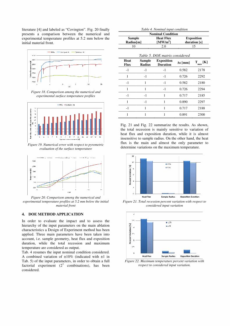
literature [4] and labeled as “Covington”. Fig. 20 finally
presents a comparison between the numerical and
experimental temperature profiles at 5.2 mm below the
initial material front.
Figure 18. Comparison among the numerical and
experimental surface temperature profiles
Figure 19. Numerical error with respect to pyrometric
evaluation of the surface temperature
Figure 20. Comparison among the numerical and
experimental temperature profiles at 5.2 mm below the initial
material front
4. DOE METHOD APPLICATION
In order to evaluate the impact and to assess the
hierarchy of the input parameters on the main ablation
characteristics a Design of Experiment method has been
applied. Three main parameters have been taken into
account, i.e. sample geometry, heat flux and exposition
duration, while the total recession and maximum
temperature are considered as output.
Tab. 4 resumes the input nominal condition considered.
A combined variation of ±10% (indicated with ±1 in
Tab. 5) of the input parameters, in order to obtain a full
factorial experiment (23 combinations), has been
considered.
Table 4. Nominal input condition
Nominal Condition
Sample
Radius[m]
Heat Flux
[MW/m2]
Exposition
duration [s]
10 2.0 15
Table 5. DOE matrix considered
Heat
Flux
Sample
Radius
Exposition
Duration Δs [mm] T
max [K]
-1 -1 -1 0.582 2178
1 -1 -1 0.726 2292
-1 1 -1 0.582 2180
1 1 -1 0.726 2294
-1 -1 1 0.717 2185
1 -1 1 0.890 2297
-1 1 1 0.717 2188
1 1 1 0.891 2300
Fig. 21 and Fig. 22 summarize the results. As shown,
the total recession is mainly sensitive to variation of
heat flux and exposition duration, while it is almost
insensitive to sample radius. On the other hand, the heat
flux is the main and almost the only parameter to
determine variations on the maximum temperature.
Figure 21. Total recession percent variation with respect to
considered input variation
Figure 22. Maximum temperature percent variation with
respect to considered input variation.

5. CONCLUSIONS
A FEM numerical approach has been developed and
implemented to perform the thermal analysis of ablative
materials in high temperature conditions.
The thermal properties of PICA ablators has been
included in the analysis in order to compare numerical
results with the outcomes of analogous experimental
and numerical tests reported in literature. The model has
been therefore successfully verified and validated.
The statistical Design Of Experiments (DOE) technique
has been applied to verify the thermal behaviour of the
materials in different conditions. A hierarchy on the
input parameters has been assessed.
The model will be applied to innovative ablative
material in course of development and characterization
at CIRA and also to design aero-thermal tests in Plasma
Wind Tunnel facilities.
6. REFERENCES
1. Venkatapathy, E., Laub, B., Hartman, G.J, Arnold,
J.O., Wright, M.J., Allen, G.A. (2009). Thermal
protection system development, testing, and
qualification for atmospheric probes and sample
return missions Examples for Saturn, Titan and
Stardust-type sample return. Advances in Space
Research 44, 138-150.
2. Williams, S.D., Curry, D.M. (1992). Thermal
Protection Materials. Reference Publication 1289,
NASA.
3. Tran H.K., et al. (1997). Phenolic Impregnated
Carbon Ablators (PICA) as Thermal Protection
Systems for Discovery Missions. Technical
Memorandum 110440, NASA.
4. Covington, M.A. (2004). Performance of a Light-
Weight ablative thermal protection material for the
Stardust Mission sample return capsule. In Proc. 2nd
"International Planetary Probe Workshop", Moffett
Field, California.
5. Milos, F.S., Chen, Y., Squire, T.H. (1999). Updated
ablation and thermal response program for
spacecraft heatshield analysis. Journal of Spacecraft
and Rockets 36(3), 475-483.
6. Dec, J.A., Brown, R.D. (2006). An approximate
Ablative Thermal Protection System Sizing Tool for
Entry System Design. In Proc. 44th
AIAA
"Aerospace Sciences Meeting and Exhibit", Reno,
Nevada.
7. ANSYS Inc. (2011). ANSYS Parametric Design
Language Guide, Release 14.0.