Embed Size (px)
Citation preview

Author’s Name Name of the Paper Session
DYNAMIC POSITIONING CONFERENCE September 28-30, 2004
DP Design & Control System
A Feasible Concept of Bi-axial Controlled DP for FPSOs in Benign Environment
Onno A.J. Peters Jaap-Harm Westhuis
IHC Gusto Engineering BV (Netherlands)
Jo. A. Pinkster
Delft University of Technology (Netherlands)

O.A.J. Peters, IHC Gusto Engineering BV A Feasible Concept of Bi-axial Controlled DP for FPSO’s in Benign Environment
ABSTRACT The idea of dynamic positioning using bi-axial control to reduce the power requirements was introduced and tested already in the late 1980s by Pinkster and Davison. The basis of this control is that the vessel is freely weathervaning, similar to single point moored vessels. This type of control is also called weathervaning DP. It must not be confused with the weathervaning mode of normal DP vessels, since bi-axial DP is a passive heading control. Computational simulations, model tests and full-scale tests have shown in the past that this principle is reliable, results in stable DP control and minimizes power consumption. For deep water, DP systems can provide a flexible and cost-effective station keeping solution compared to conventional moored systems. Recent studies have shown such a feasible and cost-effective design of a DP-FPSO with a conventional DP system in relative mild conditions. Compared to a mooring system, a DP controlled FPSO becomes cost-effective, when field installation-time and installation-costs are reduced, and thus earlier production revenues can be made. By applying bi-axial control, reduction of investment in DP equipment and reduction of operational costs are possible compared to conventional DP control. Combining well-established technologies, proven technical solutions, state of the art design practice and DP design experience, a feasible and cost-effective FPSO with bi-axial DP control has been designed. This paper outlines the theoretical hydrodynamic background and technical naval design aspects of the bi-axial DP controlled FPSO. A comparison is made with conventional DP control and with a conventional single point mooring system.
Dynamic Positioning Conference September 28-30, 2003 Page 1

O.A.J. Peters, IHC Gusto Engineering BV A Feasible Concept of Bi-axial Controlled DP for FPSO’s in Benign Environment
INTRODUCTION The concept of bi-axial DP control has been investigated already in the late 1980’s (ref. [1] and [2]), based on ideas presented in ref. [3] .It proved to be a feasible and reliable dynamic positioning solution. Computational simulations (ref. [1]), model tests (ref. [2]) and full scale tests (ref. [4] and [5]) showed the possibility to keep position and significant reduction of power consumption. However, it has never been applied to large vessels. In the 1980’s use of dynamic positioning increased rapidly, since it was introduced in the 1960’s. Initially DP systems were applied to relative small vessels like survey/exploration ships and to larger ships such as the drill ships. Since the late 1980’s, the size of DP vessels increased only slightly from a displacement in the order of 130,000 DWT to a displacement in the order of 154,000 DWT today. This was possible due to development of new thruster types and increasing thruster size, larger E-motors and generator-sets, better electrical power control technology and computerization. Due to availability of different types of and/or larger thrusters, DP control is becoming feasible for large vessels too. With the development of oil fields in deeper water, the relative investment costs of passive mooring systems have increased substantially. Especially for marginal fields or fields where relocation is required, the hardware and installation costs can be significant. A DP system can provide a reliable and cost-effective solution. Recent years, numerous DP-FPSO design studies and investigations have been performed, but still there is only one FPSO with full DP (being the SEILLEAN). This paper deals with the theoretical background, vessel and DP system design, power minimization and areas of application of bi-axial DP for large FPSO’s. Designs for Brazilian and West African waters are presented, showing the feasibility of bi-axial DP for mild environment with strong squall events. This paper is intended to lecture about the DP solutions and not to answer the question whether to choose a mooring or a DP system.
Figure 1: SEILLEAN in full operation
Dynamic Positioning Conference September 28-30, 2003 Page 2

O.A.J. Peters, IHC Gusto Engineering BV A Feasible Concept of Bi-axial Controlled DP for FPSO’s in Benign Environment
THEORETICAL BACKGROUND Modern DP control systems can be divided in two separate functions:
1. Control based on feed back of position measurement 2. Control based on measurement/estimate of the environmental forces
The control system usually relies on the first function, which is the so-called PDI-control. The second function is often called the KALMAN-control, containing a mathematical model of the vessel behavior and signal filters. Conventional DP systems are designed to keep the control point of a vessel on a desired position (xd, yd) and at a desired heading (ψd), i.e. the system is controlling the earthbound position and heading. This is a triple-axis control, consisting of two translation axes and one rotation axis. The equations for the PDI-control algorithm for this triple axis control are:
∫∫∫
∆⋅+∆⋅+∆⋅
∆⋅+∆⋅+∆⋅
∆⋅+∆⋅+∆⋅
===
dtIDP
dtyIyDyP
dtxIxDxP
MFF
yyy
xxx
req
reqy
reqx
ψψψ ψψψψ &
&
&
,
,
,
)3()2()1(
Unless minimization of wave frequent motions is desired, there is no need for heading control and thus the vessel may weathervane freely. Most DP systems have the availability of weathervaning mode to minimize thruster power usage. In principle, the optimum heading is found when the combination of mean environmental forces in x- and y-direction and the mean environmental heading moment are resulting in a minimized thrust allocation. For simplicity, the optimum heading is often defined as the heading at which the mean environmental heading moment becomes zero. By changing the desired heading the heading of the vessel is still actively controlled. Thus, it is still a triple-axes control. In principle, it is impossible to measure all the environmental components. Normally, only wind speed and wind direction are measured directly. Based on a wind coefficient database, the longitudinal and transverse wind force and wind moment are then estimated. The database should contain coefficients for different vessel loading conditions. This is the so-called wind feed forward system. In recent years a reliable and accurate system has been developed to estimate the wave drift forces and predict the sea-state, wave direction and spreading (ref. [6]); however this system is not yet commercially available. This so-called wave feed forward system can significantly reduce the dynamic offset and/or reduce the fuel consumption. Also systems to measure the surface current are in existence (ref. [7]). Estimate of the optimum heading may be based on the KALMAN-control. The KALMAN-control compares the actual measured position with a model prediction. Based on the difference between the measured and predicted position, the environmental forces and moment is predicted. The KALMAN-control performs better when wind, wave and current measurements can be used as input. Another frequently used method is to compute the optimal heading by monitoring the obtained thrust forces in x- and y-direction and obtained thrust moment. However, these two methods generally react slowly on rapid changes of environmental conditions. To effectively control the heading (i.e. to obtain Mψ,req) opposing transverse forces at each end of the vessel should be applied. However this contradicts with the required transverse force Fy,req. This implies that power is used to control the heading, and thus installation of thruster power is needed which is not always used effectively.
Dynamic Positioning Conference September 28-30, 2003 Page 3

O.A.J. Peters, IHC Gusto Engineering BV A Feasible Concept of Bi-axial Controlled DP for FPSO’s in Benign Environment
To reduce the installed power and costs, the bi-axial control was introduced. This was done by placing all thrusters in the fore ship at a specified distance from the vessel longitudinal center of gravity. The control algorithm for required moment (eq. 3) is changed to: (4) xreqyreq COTFM ⋅= ,,ψ
The parameter COTx is short for the center of thrust, in principle being the weighted center of the thruster. By concentrating the thrusters at one end of the vessel and applying bi-axial control, a system is created which can be compared with single point moored systems. For single point moored systems fishtailing can be an issue. It also may be a problem for bi-axial DP control, however in lesser extend because of active control instead of passive reaction at the mooring point. Fishtailing occurs when instability or low stability around the equilibrium mean heading and/or low yaw rate damping is present. If the stability issue can not be solved and yaw rate damping is low, damping can be created with thrusters in the aft ship. The same could be done for bi-axial DP, where the amount of damping can be controlled by the derivative part of eq. 3. This would result in: ψψψ &∆⋅+⋅= DCOTFM xreqyreq ,, (5) Requirement of additional damping depends on selection of COT, Center of Rotation (COR) and P-D-I coefficients. Also it should only be applied when analysis shows that the installed power or power usage is less than without yaw damping or that the system does not react too slowly on rapid changes of the environment. In conventional DP, the control point or Center of Rotation (COR) is normally chosen at the longitudinal center of gravity. For bi-axial DP, the COT is a more obvious choice for the COR. However, another location (both in longitudinal and transverse direction) may also be chosen with the restriction that the bi-axial DP may become unstable when the COR is chosen too far aft. Also, the lower the stability the more action may be required from the thruster system, as was concluded in ref. [1] and [3].This also becomes clear when looking at a pendulum as presented in figure 2. In this figure the trolley represents the COR and the spring represents the thrusters (COT). The square represents the center of external force, which normally lies close to the longitudinal center of gravity. For the pendulum, only the gravity force takes effect. This figure clarifies that the pendulum will stabilize to a unique equilibrium position when the center of rotation is above the center of gravity (fig. 2a), whereas the unstable pendulum may end up in oscillating motion or an unfavorable equilibrium position.
g
Figure 2a: Stable Pendulum
gc
Figure 2b: Unstable Pendulum
Dynamic Positioning Conference September 28-30, 2003 Page 4

O.A.J. Peters, IHC Gusto Engineering BV A Feasible Concept of Bi-axial Controlled DP for FPSO’s in Benign Environment
FPSO CONCEPTS The feasibility of bi-axial DP of two concepts has been investigated. The first concept is based on an early production DP-FPSO for Brazilian waters (ref. [8], figure 3). The second concept is based on a new-built FPSO with an external turret. Both concepts were developed within the IHC Caland Group.
Figure 3: Early production DP-FPSO concept (conventional DP)
Concept 1 The DP-FPSO, proposed for operations offshore Brazil, is based on the conversion of an existing Suezmax oil tanker. The vessel particulars are presented in table 1. In the initial concept a conventional DP system was applied. A bi-axial DP system is applied to this concept to investigate the difference in installed thruster power and the difference in dynamic behavior, with the aim to further reduce conversion/investment costs and/or operation costs. Since, bi-axial DP requires the COR to be forward of the amidships, the general lay-out is changed. The general lay-out of the DP-FPSO is shown in figure 5. The moonpool and riser installation derrick are placed just 7 m forward of the longitudinal center of gravity, instead of -35 m aft of LCG in the conventional DP concept. This position is not selected more forward to restrict the vertical motion and thus the heave compensation requirements. Consequently, the riser storage and handling equipment and parts of the process are shifted. In the original conventional DP concept (ref. [8]) 6x2.7MW retractable azimuth thrusters were added, of which two were placed between the engine room and the cargo tanks and four were placed in the fore ship. The existing main propulsion and tunnel thrusters were required to be used by the DP system. For the bi-axial concept only 4x3.6MW retractable azimuth thrusters are placed in the fore ship. That is in total 14.4 MW added thruster power instead of 16.2 MW in the original conversion concept. The existing thruster system is also used. The rudder is not used during DP. By applying a small amount of heading damping (eq. 5) and using the aft tunnel thruster to generate the damping, it is possible to use 4x3.6MW azimuth thrusters instead of 4x4.0MW.
Dynamic Positioning Conference September 28-30, 2003 Page 5

O.A.J. Peters, IHC Gusto Engineering BV A Feasible Concept of Bi-axial Controlled DP for FPSO’s in Benign Environment
Conversion costs are reduced, since no thrusters are required in the aft pump room. Conversion work is only required in the forward hold. Also the investment cost of the thruster system is expected to be reduced, since the CAPEX vs. thruster power ratio is expected to be lower for larger thruster systems. The thruster system exists of the thruster, the drive, the control system (like frequency converter) and the retrieval system.
Concept 2 The second concept is a new-built FPSO sized in the order of 2 million barrels storage capacity, intended for West of African areas. For these areas, large FPSO’s are fitted with either spread mooring or single point mooring systems. Selection between these two systems is largely based on capital costs of the mooring system and motional behavior of the FPSO. Especially the swell condition (i.e. long period waves) can have a crucial influence on the selection. For this concept, favorable motion characteristics are found, making it possible to select a single point mooring system. Consequently, also a bi-axial DP system can be feasible. Especially for large water depth, such a system can be competitive with a single point moored system. The new-built FPSO concept is fitted with an external riser turret system. The FPSO is equipped with 6x3.6MW retractable azimuth thrusters (i.e. 21.6MW installed thruster power). The vessel particulars are presented in table 1. Only the minimum draft condition is investigated, since wind loading is expected to be governing above the wave drift and current loads, especially during the squall events. The lay-out of this concept is shown in figure 6.
table 1 Concept 1 Concept 2
Length Lpp 233.0 270.0 m Length Loa 245.6 Breadth 42.5 58.0 m Depth 21.0 32.0 m Draft 12.5 9.4 m Displacement 106,000 140,000 t Crude oil storage capacity (approx.) 600,000 2,000,000 bls Longitudinal center of gravity (LCG) 124.5 135.0 m Center of Rotation wrt. LCG 7.0 152.0 m Center of Thrust wrt. LCG 85.7 103.0 m
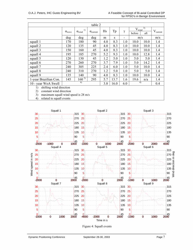
Environmental conditions To verify the feasibility of bi-axial DP, 9 measured squall events are simulated for both concepts. The squall events are shown in figure 4. During all squall events the wind velocity increases to 28 m/s and is shifting such that the direction is 180° (for axes convention figure 7) when the maximum wind velocity is reached. For concept 1, the 9 squall events are combined with sea-states belonging to an averaged wind speed (i.e. average over the wind speed before and after the squall event). In addition, concept 1 is to be able to operate in a 1-year return Brazilian condition with an offset accuracy within 6% of the water depth. For concept 2, the 9 squall events are combined with a 10 year West-African swell condition. Spreading of the environment is applied. Details of the environmental conditions are given in table 2.
Dynamic Positioning Conference September 28-30, 2003 Page 6
O.A.J. Peters, IHC Gusto Engineering BV A Feasible Concept of Bi-axial Controlled DP for FPSO’s in Benign Environment
table 2 Vwind 3)
αwave αwind 1) αcurrent Hs Tp γ before aft
Vcurrent
deg deg deg m s - m/s m/s squall 1 170 180 90 4.0 8.3 1.0 10.0 10.0 1.4 squall 2 120 135 45 4.0 8.3 1.0 10.0 10.0 1.4 squall 3 150 160 45 4.0 8.3 1.0 10.0 10.0 1.4 squall 4 195 185 270 5.2 9.3 1.0 10.0 12.8 1.4 squall 5 120 130 45 1.2 5.0 1.0 5.0 5.0 1.4 squall 6 270 260 270 3.7 7.9 1.0 5.0 14.2 1.4 squall 7 240 305 225 2.4 6.0 1.0 5.0 10.0 1.4 squall 8 240 310 270 1.2 5.0 1.0 5.0 5.0 1.4 squall 9 135 140 90 4.0 8.3 1.0 10.0 10.0 1.4 1-year Brazilian Con. 145 160 2) 295 5.7 13.7 1.6 19.6 n/a 1.4 10 - year WoA Swell 4) 3.8 16.0 6.0 4) 0.4
1) shifting wind direction 2) constant wind direction 3) maximum squall wind speed is 28 m/s 4) related to squall events
-2000 -1000 0 10000
510
1520
2530
Squall 1
-1000 0 1000 20000
510
1520
2530
Squall 2
-2000 0 2000 40000
510
1520
2530
Squall 3
-2000 0 20000
510
1520
2530
Squall 4
Win
d sp
eed
in m
/s
-2000 0 20000
510
1520
2530
Squall 5
-1000 0 1000 20000
510
1520
2530
Squall 6
-1000 0 1000 20000
510
1520
2530
Squall 7
-4000 -2000 0 20000
510
1520
2530
Squall 8
Time in s-1000 0 1000 20000
510
1520
2530
Squall 9
-2000 -1000 0 100045
90135
180225
270315
-1000 0 1000 200045
90135
180225
270315
-2000 0 2000 400045
90135
180225
270315
-2000 0 200045
90135
180225
270315
-2000 0 200045
90135
180225
270315
-1000 0 1000 200045
90135
180225
270315
Win
d di
rect
ion
in d
eg
-1000 0 1000 200045
90135
180225
270315
-4000 -2000 0 200045
90135
180225
270315
-1000 0 1000 200045
90135
180225
270315
Figure 4: Squall events
Dynamic Positioning Conference September 28-30, 2003 Page 7

O.A.J. Peters, IHC Gusto Engineering BV A Feasible Concept of Bi-axial Controlled DP for FPSO’s in Benign Environment
SIMULATIONSThe DP simulations are carried out with in-house developed software. This DP simulation model is based on the low frequent equations of motion, the high frequent basic motion are superimposed based on Response Amplitude Operators. Furthermore, the model is using a wave drift force estimate based on the full quadratic transfer function (QTF). The full QTF is found from 3-D diffraction theory. The KALMAN control is not included in the simulation model. The wind loading is based on estimates of the wind coefficients using a building block method. This building block method takes into account shielding effects and input of different hull types, lattice structures and (tapered) cylinders or blocks are possible. The simulations are carried out without wind feed forward. The current force coefficients are based on OCIMF data (ref. [9]). The results of the simulations are presented in plots showing the extreme vessel positions, starting position and average position. The extreme positions consist of the minimum and maximum earth fixed position of the COR and of the heading. Also shown are the extreme COG locations, the time trace of COR and the maximum radial offset.
Results Concept 1 The 9 simulated squall events are shown in figures 8 and 17. For the worst squall event, in terms of offset and thruster loading, an additional simulation is carried out to simulate a single thruster failure at a critical moment in time, just before maximum thruster power is required. This failure event is shown in figure 11 and can be compared to the intact condition shown in figure 12. Figures 18 and 19 are showing that the bi-axial concept is able to stay on position in the 1-year return Brazilian condition. For the intact case the maximum radial offset is approximately 27.2 m. In case just before the maximum offset event a single azimuth thruster is failing, the maximum offset becomes approximately 36.2 m. With the maximum offset limit of 6% of the water depth, this implies that the early production vessel is able to operate in water depth larger than approximately 600 m. Comparable results are found for the conventional DP concept, see figures 20 and 21. These figures show the behavior assuming that the conventional system is able to find and keep the optimum heading defined as the heading for which the required thrust moment is zero. This heading is 36°, whereas an average heading of approximately 27° is found for bi-axial DP.
Results Concept 2 The simulation results of the 9 squall events are presented in figures 22 to 30. The simulations are performed for a 3-hour real-time duration. During the squall events a single thruster failure is simulated, leaving the DP system with 5 thrusters. The failure occurs just before maximum thruster power is required. The largest offset is found during squall event 2, being approximately 20.5 m. This implies that this concept is able to operate in a water depth larger than approximately 150 m, assuming an allowable 15% of the water depth.
Dynamic Positioning Conference September 28-30, 2003 Page 8

O.A.J. Peters, IHC Gusto Engineering BV A Feasible Concept of Bi-axial Controlled DP for FPSO’s in Benign Environment
CONCLUSIONS Application of bi-axial DP is investigated for two FPSO concepts. For the early production FPSO concept a reduction of the installed thruster power and conversion cost is achieved by applying bi-axial DP instead of conventional DP. Both early production FPSO concepts showed comparable results in terms of motional behavior (heave, roll and pitch), positioning accuracy and mean power consumption. For West African waters, a feasible bi-axial DP 2mln barrel FPSO concept with an external turret is made, requiring only 21.6MW of installed thruster power. The installed power is required to be able to keep position during squall events, with the possibility of a single thruster failure. During normal operations a very low power demand is found. Such a thruster system can be very competitive with a mooring system. A bi-axial DP system is able to react passively on large and rapid environmental changes (like squall events), without the requirement of algorithms determining the best heading during these events.
Dynamic Positioning Conference September 28-30, 2003 Page 9

O.A.J. Peters, IHC Gusto Engineering BV A Feasible Concept of Bi-axial Controlled DP for FPSO’s in Benign Environment
REFERENCES [1] Pinkster, J.A., Nienhuis, U.:
“Dynamic Positioning of Large Tankers at Sea”, OTC paper 5208, Offshore Technology Conference, Houston 1986
[2] Davison, N.J., Thomas, N.T., Nienhuis, U., Pinkster, J.A: “Application of an Alternative Concept in Dynamic Positioning to Tanker Floating Production System”, OTC paper 5444, Offshore Technology Conference, Houston 1987
[3] Pinkster, J.A.: “Dynamic Positioning of Vessels at Sea”, Paper No. 105, Course and Lectures at the Department of Experimental Methods in Mechanics, CISM, Udine, Marin Publication No. 419, October 1971
[4] Pinkster, J.A., Hagiwara, H., Shoji, R., Fukuda, H.: “A Study on Weathervaning Dynamic Positioning System”, Delft University of Technology Report 1201-P, September 1999, Delft, the Netherlands and Journal of Japan Institute of Navigation, Vol. 101, September 1999, pp 83-93
[5] Hagiwara, H., Shoji, R., Fukuda, H., Pinkster, J.A: “Onboard Experiments on Weathervaning Dynamic Positioning /tracing and Automatic Berthing”, Delft University of Technology, Report 1293-P and Proceedings of the 7th Int. Conference on Methods and Models in Automation and Robotics, MMAR’2001, 28-31 August 2001, Miedzyzdroje, Poland
[6] Aalbers, A (MARIN): “Wave feed forward DP and analysis of the effect on Shuttle Tanker Operation”, Dynamic Positioning Conference, September 2004
[7] Jan van Smirren, Caroline Nicholas, Cathy Primrose (Fugro GEOS, RD Instruments Inc.): “A Surface Current Measurement System to Support DP Operations”, Dynamic Positioning Conference, September 2003
[8] Poldervaart, L., Cann, B. van, Westhuis, J.: “A DP-FPSO as a First-Stage Field Development Unit for Deepwater Prospects in Relative Mild Environments”, OTC paper 16484, May 2004
[9] Oil Companies International Marine Forum (OCIMF): “Prediction of Wind and Current Loads on VLCC’s”, 1994
Dynamic Positioning Conference September 28-30, 2003 Page 10

O.A.J. Peters, IHC Gusto Engineering BV A Feasible Concept of Bi-axial Controlled DP for FPSO’s in Benign Environment
Figure 5: General lay-out Concept 1 - early production FPSO with bi-axial control
Dynamic Positioning Conference September 28-30, 2003 Page 11

O.A.J. Peters, IHC Gusto Engineering BV A Feasible Concept of Bi-axial Controlled DP for FPSO’s in Benign Environment
Figure 6: General lay-out of Concept 2 - new-built 2mln barrel FPSO
Dynamic Positioning Conference September 28-30, 2003 Page 12

O.A.J. Peters, IHC Gusto Engineering BV A Feasible Concept of Bi-axial Controlled DP for FPSO’s in Benign Environment
Figure 7: Axes convention
Dynamic Positioning Conference September 28-30, 2003 Page 13

O.A.J. Peters, IHC Gusto Engineering BV A Feasible Concept of Bi-axial Controlled DP for FPSO’s in Benign Environment
-150 -100 -50 0 50 100-150
-100
-50
0
50
100
150
x_COR [m]
y_C
OR
[m]
Bi-axial, COT=85.7m COR=7.0m, squall 1, wa:170 sq:180 cu: 90
timetrace CORextreme positions CORmean position CORextreme positions COGmean vessel contourextreme vessel contoursstarting position vesselmax radial offset:6.5 [m]
Figure 8: Concept 1 biaxial – squall event 1
-150 -100 -50 0 50 100-150
-100
-50
0
50
100
150
x_COR [m]
y_C
OR
[m]
Bi-axial, COT=85.7m COR=7.0m, squall 2, wa:120 sq:180 cu: 45
timetrace CORextreme positions CORmean position CORextreme positions COGmean vessel contourextreme vessel contoursstarting position vesselmax radial offset:13.3 [m]
Figure 9: Concept 1 biaxial – squall event 2
-150 -100 -50 0 50 100-150
-100
-50
0
50
100
150
x_COR [m]
y_C
OR
[m]
Bi-axial, COT=85.7m COR=7.0m, squall 3, wa:150 sq:180 cu: 45
timetrace CORextreme positions CORmean position CORextreme positions COGmean vessel contourextreme vessel contoursstarting position vesselmax radial offset:8.3 [m]
Figure 10: Concept 1 biaxial – squall event 3
-150 -100 -50 0 50 100-150
-100
-50
0
50
100
150
x_COR [m]
y_C
OR
[m]
Bi-axial, COT=85.7m COR=7.0m, squall 4, wa:195 sq:180 cu:270, intact
timetrace CORextreme positions CORmean position CORextreme positions COGmean vessel contourextreme vessel contoursstarting position vesselmax radial offset:11.0 [m]
Figure 11: Concept 1 biaxial – squall event 4, intact
-150 -100 -50 0 50 100-150
-100
-50
0
50
100
150
x_COR [m]
y_C
OR
[m]
Bi-axial, COT=85.7m COR=7.0m, squall 4, wa:195 sq:180 cu:270, single failure
timetrace CORextreme positions CORmean position CORextreme positions COGmean vessel contourextreme vessel contoursstarting position vesselmax radial offset:16.9 [m]
Figure 12: Concept 1 biaxial – squall event 4, failure
-150 -100 -50 0 50 100-150
-100
-50
0
50
100
150
x_COR [m]
y_C
OR
[m]
Bi-axial, COT=85.7m COR=7.0m, squall 5, wa:120 sq:180 cu: 45
timetrace CORextreme positions CORmean position CORextreme positions COGmean vessel contourextreme vessel contoursstarting position vesselmax radial offset:15.1 [m]
Figure 13: Concept 1 biaxial – squall event 5
Dynamic Positioning Conference September 28-30, 2003 Page 14

O.A.J. Peters, IHC Gusto Engineering BV A Feasible Concept of Bi-axial Controlled DP for FPSO’s in Benign Environment
-150 -100 -50 0 50 100-150
-100
-50
0
50
100
150
x_COR [m]
y_C
OR
[m]
Bi-axial, COT=85.7m COR=7.0m, squall 6, wa:270 sq:180 cu:270
timetrace CORextreme positions CORmean position CORextreme positions COGmean vessel contourextreme vessel contoursstarting position vesselmax radial offset:7.6 [m]
Figure 14: Concept 1 biaxial – squall event 6
-150 -100 -50 0 50 100-150
-100
-50
0
50
100
150
x_COR [m]
y_C
OR
[m]
Bi-axial, COT=85.7m COR=7.0m, squall 7, wa:240 sq:180 cu:225
timetrace CORextreme positions CORmean position CORextreme positions COGmean vessel contourextreme vessel contoursstarting position vesselmax radial offset:6.5 [m]
Figure 15: Concept 1 biaxial – squall event 7
-150 -100 -50 0 50 100-150
-100
-50
0
50
100
150
x_COR [m]
y_C
OR
[m]
Bi-axial, COT=85.7m COR=7.0m, squall 8, wa:240 sq:180 cu:270
timetrace CORextreme positions CORmean position CORextreme positions COGmean vessel contourextreme vessel contoursstarting position vesselmax radial offset:8.2 [m]
Figure 16: Concept 1 biaxial – squall event 8
-150 -100 -50 0 50 100-150
-100
-50
0
50
100
150
x_COR [m]
y_C
OR
[m]
Bi-axial, COT=85.7m COR=7.0m, squall 9, wa:135 sq:180 cu: 90
timetrace CORextreme positions CORmean position CORextreme positions COGmean vessel contourextreme vessel contoursstarting position vesselmax radial offset:4.4 [m]
Figure 17: Concept 1 biaxial – squall event 9
Dynamic Positioning Conference September 28-30, 2003 Page 15

O.A.J. Peters, IHC Gusto Engineering BV A Feasible Concept of Bi-axial Controlled DP for FPSO’s in Benign Environment
-150 -100 -50 0 50 100-150
-100
-50
0
50
100
150
x_COR [m]
y_C
OR
[m]
Bi-axial, COT=85.7m COR=7.0m, 1-year, wa:140 wi:160 cu:295, intact
timetrace CORextreme positions CORmean position CORextreme positions COGmean vessel contourextreme vessel contoursstarting position vesselmax radial offset:27.6 [m]
Figure 18: Concept 1 biaxial, intact, Brazil
-150 -100 -50 0 50 100-150
-100
-50
0
50
100
150
x_COR [m]
y_C
OR
[m]
Bi-axial, COT=85.7m COR=7.0m, 1-year, wa:140 wi:160 cu:295, single failure
timetrace CORextreme positions CORmean position CORextreme positions COGmean vessel contourextreme vessel contoursstarting position vesselmax radial offset:36.2 [m]
Figure 19: Concept 1 biaxial, failure, Brazil
-100 -50 0 50 100 150
-100
-50
0
50
100
150
x_COR [m]
y_C
OR
[m]
Conventional DP, COR=-35m, 1-year, wa:140 wi:160 cu:295, zero required moment, intact
timetrace CORextreme positions CORmean position CORextreme positions COGmean vessel contourextreme vessel contoursstarting position vesselmax radial offset:19.7 [m]
Figure 20: Concept 1 conventional, intact, Brazil
-100 -50 0 50 100 150
-100
-50
0
50
100
150
x_COR [m]
y_C
OR
[m]
Conventional DP, COR=-35m, 1-year, wa:140 wi:160 cu:295, zero required moment, single failure
timetrace CORextreme positions CORmean position CORextreme positions COGmean vessel contourextreme vessel contoursstarting position vesselmax radial offset:42.0 [m]
Figure 21: Concept 1 conventional, intact, Brazil
Dynamic Positioning Conference September 28-30, 2003 Page 16

O.A.J. Peters, IHC Gusto Engineering BV A Feasible Concept of Bi-axial Controlled DP for FPSO’s in Benign Environment
-350 -300 -250 -200 -150 -100 -50 0 50 100-200
-150
-100
-50
0
50
100
150
200
x_COR [m]
y_C
OR
[m]
COT=99m COR=152m, 10yr swell+squall 1, wa:170 sq:180 cu: 90
timetrace CORextreme positions CORmean position CORextreme positions COGmean vessel contourextreme vessel contoursstarting position vesselmax radial offset:5.5 [m]
Figure 22: Concept 1 – squall event 1
-350 -300 -250 -200 -150 -100 -50 0 50 100
-100
-50
0
50
100
150
200
250
x_COR [m]
y_C
OR
[m]
COT=99m COR=152m, 10yr swell+squall 2, wa:120 sq:180 cu: 45
timetrace CORextreme positions CORmean position CORextreme positions COGmean vessel contourextreme vessel contoursstarting position vesselmax radial offset:10.8 [m]
Figure 23: Concept 2 – squall event 2
-350 -300 -250 -200 -150 -100 -50 0 50 100
-100
-50
0
50
100
150
200
250
x_COR [m]
y_C
OR
[m]
COT=99m COR=152m, 10yr swell+squall 3, wa:150 sq:180 cu: 45
timetrace CORextreme positions CORmean position CORextreme positions COGmean vessel contourextreme vessel contoursstarting position vesselmax radial offset:7.5 [m]
Figure 24: Concept 2 – squall event 3
-350 -300 -250 -200 -150 -100 -50 0 50 100-200
-150
-100
-50
0
50
100
150
200
x_COR [m]
y_C
OR
[m]
COT=99m COR=152m, 10yr swell+squall 4, wa:195 sq:180 cu:270
timetrace CORextreme positions CORmean position CORextreme positions COGmean vessel contourextreme vessel contoursstarting position vesselmax radial offset:2.0 [m]
Figure 25: Concept 2 – squall event 4
-350 -300 -250 -200 -150 -100 -50 0 50 100
-100
-50
0
50
100
150
200
250
x_COR [m]
y_C
OR
[m]
COT=99m COR=152m, 10yr swell+squall 5, wa:120 sq:180 cu: 45
timetrace CORextreme positions CORmean position CORextreme positions COGmean vessel contourextreme vessel contoursstarting position vesselmax radial offset:6.8 [m]
Figure 26: Concept 2 – squall event 5
-350 -300 -250 -200 -150 -100 -50 0 50 100-300
-250
-200
-150
-100
-50
0
50
100
x_COR [m]
y_C
OR
[m]
COT=99m COR=152m, 10yr swell+squall 6, wa:270 sq:180 cu:270
timetrace CORextreme positions CORmean position CORextreme positions COGmean vessel contourextreme vessel contoursstarting position vesselmax radial offset:8.1 [m]
Figure 27: Concept 2 – squall event 6
Dynamic Positioning Conference September 28-30, 2003 Page 17

O.A.J. Peters, IHC Gusto Engineering BV A Feasible Concept of Bi-axial Controlled DP for FPSO’s in Benign Environment
-350 -300 -250 -200 -150 -100 -50 0 50 100-300
-250
-200
-150
-100
-50
0
50
100
x_COR [m]
y_C
OR
[m]
COT=99m COR=152m, 10yr swell+squall 7, wa:240 sq:180 cu:225
timetrace CORextreme positions CORmean position CORextreme positions COGmean vessel contourextreme vessel contoursstarting position vesselmax radial offset:20.5 [m]
Figure 28: Concept 2 – squall event 7
-350 -300 -250 -200 -150 -100 -50 0 50 100-300
-250
-200
-150
-100
-50
0
50
100
x_COR [m]
y_C
OR
[m]
COT=99m COR=152m, 10yr swell+squall 8, wa:240 sq:180 cu:270
timetrace CORextreme positions CORmean position CORextreme positions COGmean vessel contourextreme vessel contoursstarting position vesselmax radial offset:7.9 [m]
Figure 29: Concept 2 – squall event 8
-350 -300 -250 -200 -150 -100 -50 0 50 100
-100
-50
0
50
100
150
200
250
x_COR [m]
y_C
OR
[m]
COT=99m COR=152m, 10yr swell+squall 9, wa:135 sq:180 cu: 90
timetrace CORextreme positions CORmean position CORextreme positions COGmean vessel contourextreme vessel contoursstarting position vesselmax radial offset:5.7 [m]
Figure 30: Concept 2 – squall event 9
Dynamic Positioning Conference September 28-30, 2003 Page 18