Embed Size (px)
Citation preview

A Feasibility Study of a
Neutrino Source
Based on a MuonStorage Ring
Contributions from: 20 FTE during 6 months at Fermilab plus about50 FTE from other labs. 12 named authors from CERN, 3 from RAL
edited by:
Norbert HoltkampDavid Finley

Charge for the purpose of this study
1. A design concept for a muon storage ring and associated support
facilities that could, with reasonable assurance, meet performance
goals required to support a compelling neutrino based research
program.
2. Identification of the likely cost drivers within such a facility.
3. Identification of an R&D program that would be required to
address key areas of technological uncertainty and
cost/performance optimization within this design, and that would,
upon successful completion, allow one to move with confidence
into the conceptual design stage of such a facility.
4. Identification of any specific environmental, safety, and health
issues that will require our attention.

��������������� � ��������� �����
Sub-Component Status
Can we build it?
Risk Save money?
Make it easier?
Responsible person for the chapter in the report
Proton Driver ok
yes
moderate yesless intensitylonger bunches
W. Chou
Target not ok
no
high power on target T. Gabriel, ORNLS.ChildressN. Mokhov
Decay channel + φ rot not ok
may be
high no back off in present design V.Balbekov
mini cooling(factor of 3)
(3 m LH2)
ok
yes
low no for this design
less intensity
D. Kaplan
2nd φ-rotation
(induct) linac
not ok
may be
very high only in exchange with low frequ.RF
N. HoltkampLBNL
capture not okmainly rf problem
high no (a little)lower Frequ. rf
D. Neuffer
cooling(factor of 50)
not ok
mainly rf problem
high no (a little)
lower Frequ. rf
S. GeerD.Kaplan,P.Lebrun,
1st stage linactogether with next row(RLAS)
½ okyes
moderate no CEBAFCornellC. Bohn
RLA’s ½ okyes
moderate no CEBAFCornellC. Bohn
Storage Ring okyes
moderate nocompromise flux
S. Ohnuma, TexasD. FinleyC. Johnstone
Diagnostic not ok moderate no ?

1. Energy of the Storage Ring should be 50 GeV2. Number of neutrinos/straight section is 2x10²⁰ per year3. No polarization4. Capability to switch between µµ+ and µµ+
5. Baseline for facility Fermilab to SLAC/LBNL
Table 1: Set of parameters chosen for the feasibility studyfollowing a very early assessment of the goals for the physicsstudy.
1. Given the ongoing study at Fermilab for a fast cycling protonsynchrotron (15 Hz) with 16 GeV extraction energy, thenumber of protons per pulse required on target is at least2××1013. This as approximately 1 MW beam power on target.
2. The transverse emittance of the muon beam after the coolingchannel has to be small enough, in order to have the beamdivergence in the straight section to be less then 1/10 of thedecay angle, which is 1/γγ = 2 mrad. Given an invariantemittance of γγ ⋅⋅εε =3.2ππ⋅⋅mm⋅⋅rad the ββ-function would be ~400 m.This seemed reasonable.
3. Following the assumption of having ten protons per onemuon injected in the storage ring, 2××1012 muons per pulse arerequired after the cooling channel and have to be accelerated.
4. No polarization.5. The Neutrino beam is directed from Fermilab to SLAC/LBNL
with a distance of ~3000 km. This sets the slope of thestorage ring with respect to the earth surface at 22% or 13deg. Gentle enough to think of conventional installationmethods.
Table 2: Specifications for the accelerator complex of theneutrino source.

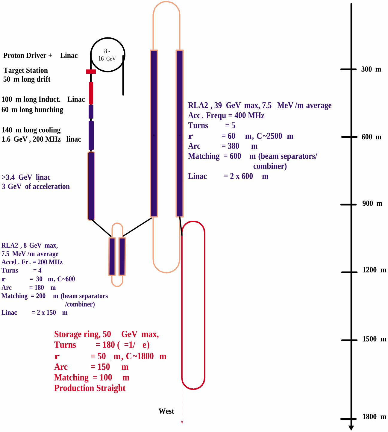
8 -16 GeV
100 m long Induct. Linac
50 m long drift
60 m long bunching
140 m long cooling1.6 GeV , 200 MHz linac
>3.4 GeV linac3 GeV of acceleration
RLA2 , 8 GeV max,7.5 MeV /m averageAccel . Fr . = 200 MHzTurns = 4r = 30 m, C~600Arc = 180 mMatching = 200 m (beam separators /combiner)Linac = 2 x 150 m
c c
RLA2 , 39 GeV max, 7.5 MeV /m averageAcc . Frequ = 400 MHzTurns = 5r = 60 m, C~2500 mArc = 380 mMatching = 600 m (beam separators/ combiner)Linac = 2 x 600 m
Proton Driver + Linac
Target Station
Storage ring, 50 GeV max,Turns = 180 ( =1/ e)r = 50 m, C~1800 mArc = 150 mMatching = 100 mProduction Straight
300 m
600 m
900 m
1200 m
1500 m
1800 mWest

PRESENT(νν -FACTORY)PHASE I
UPGRADEPHASE II
Linac (operating at 15 Hz)Kinetic energy (MeV) 400 400 1000Peak current (mA) 40 60 80Pulse length (µs) 25 80 200H- per pulse 6.3 × 10¹² 3 × 10¹³ 1 × 10¹⁴
Average beam current (µA) 15 72 240Beam power (kW) 6 29 240
Pre-booster (operating at 15Hz)Extraction kinetic energy (GeV) 3
Protons per bunch 2.5 × 10¹³
Number of bunches 4
Total number of protons 1 ×× 1014
Norm. transverse emittance(mm-mrad)
200π
Longitudinal emittance (eV-s) 2RF frequency (MHz) 7.5Average beam current (µA) 240Beam power (kW) 720
Booster (operating at 15 Hz)Extraction kinetic energy (GeV) 8 16 16Protons per bunch 6 × 10¹⁰ 7.5 × 10¹² 2.5 × 10¹³
Number of bunches 84 4 4Total number of protons 5 ×× 1012 3 ×× 1013 1 ×× 1014
Norm. transverse emittance(mm-mrad)
15π 60π 200π
Longitudinal emittance (eV-s) 0.1 2 2RF frequency (MHz) 53 1.7 7.5Extracted bunch length σb (ns) 0.2 3 1
Average beam current (µA) 12 72 240Target beam power (kW) 100 1200 4000
Proton Driver Parameters of Present, Phase I and Phase II.

Figure 1: The number of ππ+ + µµ + (filled symbols) and ππ- + µµ - (opensymbols) at 30 MeV<E<230 MeV, as a function of proton energy in thedecay channel. Yields are at 9 m downstream of an 80-cm long and0.75-cm radius carbon target, tilted by 50 mrad with respect to thesolenoid axis. RMS beam spot size σσx,y=0.214 cm. Triangles representthe yield per beam energy

Figure 1: The number of protons per pulse on an 80-cm carbon targetrequired to get 2x10²⁰ positive (filled symbols) and negative (opensymbols) muons per year in the storage ring straight section vs. protonenergy. Triangles represent corresponding beam power.

For a 1.5 MW beam, the annual hadron flux in a stationarygraphite target is 5x1021cm-2, which corresponds to severalmonths of target lifetime. The annual hadron flux (E>0.1 MeV)and dose in the hottest spot of the inner resistive coil are1.2x1020cm-2 and 3x10¹⁰ Gy, respectively. This corresponds to ~3year lifetime limit for copper and ceramic. As discussed later,other considerations also severely limit the lifetime of the resistivecoil. The annual neutron flux (E>0.1 MeV) and the dose in thehottest spot of the high field superconducting coil are 8x1017cm-2
and 1.3x10⁷ Gy, respectively, or 15 to 20 year lifetime. Theannual neutron flux (E>0.1 MeV) and dose in the hottest spot ofthe potted superconducting coil at the beam dump are7.6x1017cm-2 and 4.1x10⁷ Gy, respectively, or 7-10 year lifetimewith the current shielding. The lifetime numbers are ratheruncertain, due to lack of data for radiation damage tosuperconducting materials at neutron energies above 14 MeV.With better understanding of these effects, a shielding design canbe adapted that provides longer coil lifetime.
Residual dose rates for a 1.5 MW beam are up to 107 mSv/hr(106 R/hr) on the target, bore tube and inner resistive coil,103 mSv/hr (100 R/hr) on the CICC (cable-in-conduit conductor)coil and 102 mSv/hr (10 R/hr) on the vessel, with the requirementfor remote control and robotics. Radiation shielding requirementsbased on these rates are presented as part of the target supportfacility design.
We have chosen to design with poly-Bitter technology, which ishighly developed, capable of very high current densities, andsubjects the insulation to predominantly compressive stress.However, the life-time of poly-Bitter magnets is limited (in designsappropriate for the present application, primarily by water erosionof insulating materials and degradation of electrical contacts).

Figure 1. Overview of the Target Support Facility.

Component ExpectedLifetime
ReplacementTime
Target 3 mos 6 days Target + Bitter Coil 6 mos 7 days Target +Bitter Coil + PBW 1 yr 8 days PB Instrumentation 1 yr 5-7 days Beam Dump 5 yrs 1.5 mos High Field S/C Coils >20 yrs 9-12 mos Low Field S/C Coils >20 yrs 9-12 mos
Component Lifetimes for the Target Support Facility
Figure 1. Cutaway view of the high-field solenoid, target, andshielding in the cryostat module.
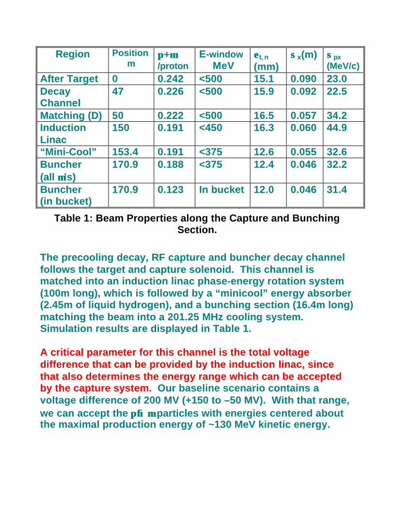
Region Positionm
ππ+µµ/proton
E-windowMeV
εε t, n
(mm)σσx(m) σσpx
(MeV/c)After Target 0 0.242 <500 15.1 0.090 23.0DecayChannel
47 0.226 <500 15.9 0.092 22.5
Matching (D) 50 0.222 <500 16.5 0.057 34.2InductionLinac
150 0.191 <450 16.3 0.060 44.9
“Mini-Cool” 153.4 0.191 <375 12.6 0.055 32.6Buncher(all µµ’s)
170.9 0.188 <375 12.4 0.046 32.2
Buncher(in bucket)
170.9 0.123 In bucket 12.0 0.046 31.4
Table 1: Beam Properties along the Capture and BunchingSection.
The precooling decay, RF capture and buncher decay channelfollows the target and capture solenoid. This channel ismatched into an induction linac phase-energy rotation system(100m long), which is followed by a “minicool” energy absorber(2.45m of liquid hydrogen), and a bunching section (16.4m long)matching the beam into a 201.25 MHz cooling system.Simulation results are displayed in Table 1.
A critical parameter for this channel is the total voltagedifference that can be provided by the induction linac, sincethat also determines the energy range which can be acceptedby the capture system. Our baseline scenario contains avoltage difference of 200 MV (+150 to –50 MV). With that range,we can accept the ππ→→µµ particles with energies centered aboutthe maximal production energy of ~130 MeV kinetic energy.

Figure 1: Beam at the end of the 47 m decay channel.Three projections of the 6-D phase space distributionsof a simulated beam are displayed. The cT-E projectionshows the energy-dependent bunch lengthening. TheX-Px projection indicates the beam phase-space size(σσ x ≅≅ 9 cm, σσPx ≅≅ 22 MeV/c). The X-Py projectionindicates the beam angular momentum associatedwith the 1.25T solenoidal focusing field.

Figure 1: Beam distributions in E-cT phase spacealong the induction linac. Distributions from L = 0, 20,40, 60, 80, and 100 m are shown.
Figure 2: Longitudinal phase space distributions ofthe µµ-beam before (above, red) and after (below,violet) the minicool energy loss insert.


Figure 1: Schematic cross section of an inductionlinac cell.

Pulsed Power System layout and Induction Cell
H20 Delay Line SCR Switched Prime Power
4 Series PFLs
MCPC Module
Cell Cables

A: B:
Figure 1: Beam distributions in energy –distance coordinates. Ashows the full beam length; B shows the distribution foldedover the 201.25 MHz periodicity, with an RF bucket for 200 MeV,200 MHz cooling.
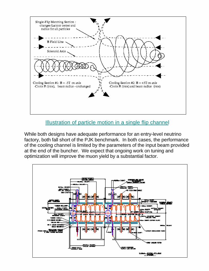
Illustration of particle motion in a single flip channel
While both designs have adequate performance for an entry-level neutrinofactory, both fall short of the PJK benchmark. In both cases, the performanceof the cooling channel is limited by the parameters of the input beam providedat the end of the buncher. We expect that ongoing work on tuning andoptimization will improve the muon yield by a substantial factor.
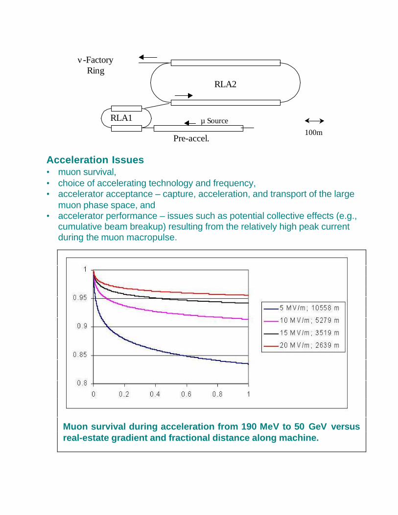
Acceleration Issues• muon survival,• choice of accelerating technology and frequency,• accelerator acceptance – capture, acceleration, and transport of the large
muon phase space, and• accelerator performance – issues such as potential collective effects (e.g.,
cumulative beam breakup) resulting from the relatively high peak currentduring the muon macropulse.
Muon survival during acceleration from 190 MeV to 50 GeV versusreal-estate gradient and fractional distance along machine.
100mmmmPre-accel.
RLA1
RLA2
µ Source
ν-FactoryRing

Constraints on the storage ring due to the geology under the Fermilab site.The 2667’ (or 813 meter) limit on the cross-section profile of the ring shown inthe lower drawing is given by the 600 foot available for the ring’s vertical dropthe and 13 degree angle between Fermilab and the West Coast .
Circumference m 1752.8Neutrino decay fraction % 39.2Production regionMatching and dispersionsuppression
m 44.1
High-beta FODO straight m 688Generalβx(max)/βy(max) 90νx/νy 86.3Natural chromaticity 12
Overall parameters of the storage ring.

Distribution of cost in percent of the total for the different subsystems and for the components summed up over thesubsystems.
Cost Total for each Sub-System
9.3%3.2%
0.7%6.5%
3.1%20.5%
10.8%12.8%
24.7%5.6%
0.0% 5.0% 10.0% 15.0% 20.0% 25.0% 30.0%
Proton Driver
Target Systems
Decay Channel
Induction Linac
Capture+Mini c.
Cooling Channel
Capture Linac
RLA 1
RLA2
Storage Ring
Su
b-s
yste
ms
percent of total
20.1%
13.7%17.5%
4.3%
3.4%6.4%
4.8%6.4%
0.9%
13.8%
0.0% 10.0% 20.0% 30.0%
Magnets
RF Source
RF Cav
Vacuum
PS
Diagn.
Cryo
Utilities
ES&H
Civil
Sys
tem
s
percent of total