Embed Size (px)
Citation preview

A R C H I V E S O F M E T A L L U R G Y A N D M A T E R I A L S
Volume 53 2008 Issue 2
R. GOTTARDI∗ , S. MIANI∗∗ , A. PARTYKA ∗∗∗
A FASTER, MORE EFFICIENT EAF
SZYBSZY I BARDZIEJ WYDAJNY PIEC ŁUKOWY
When the market is in an expansion phase, the necessity to increase the production is a must involving an expansion of
the production facilities. The revamping of an existing plant set several constrains, mainly due to the ladle size, therefore the
reduction of the tap to tap is the only solution: a faster furnace.
When the market is stable or in recession, it is necessary to reduce the transformation costs through the efficiency of the
whole process and of the production facilities, mainly the one of the melting furnace.
The present paper has the aim to catalogue the main items affecting the “faster” and the “efficient” adjectives and to
illustrate the last technological developments, such as the UHCP (Ultra High Chemical Power) furnace, that Concast has
implemented allowing a further step ahead.
Some outstanding UHCP will be analysed.
Keywords: EAF benchmark, O2 and C injection, process control tools, UHCP EAF, high productivity EAF, Heat Transfer
Efficiency
Koniunktura rynku powoduje wzrost produkcji, a to wiąże się z rozwojem oraz unowocześnianiem urządzeń do produkcji.
Modernizacja istniejących hut stwarza różne ograniczenia, głównie spowodowane wielkością kadzi, dlatego istnieje tylko jeden
sposób aby zmniejszyć czas trwania wytopu: szybsze piece. W sytuacji, gdy rynek jest stabilny lub w warunkach recesji,
konieczne jest zmniejszenie kosztów produkcji poprzez podwyższenie sprawności całego procesu lub poszczególnych etapów,
a zwłaszcza etapu topnienia wsadu. Głównym celem tego prezentowanego artykułu było skatalogowanie ważnych czynników
wpływających na ”szybkość” oraz ”sprawność” oraz zaprezentowanie najnowszych osiągnięć technologicznych, takich jak piec
UHCP (Ultra High Chemical Power), który Concast stworzył w oparciu o najnowsze rozwiązania. Pewne najważniejsze cechy
UHCP zostaną przeanalizowane.
1. Introduction
The speed and the efficiency are two characteristics
of a system that sometimes can not be present at the
same time. When the melting efficiency function fore-
sees a maximum, the theoretical optimum working point
could be just that one but, if the speed factor, i.e. tap to
tap time, is a must, it is important is to find a correla-
tion between all the factors and the system answer to the
variation of of such parameters to understand the system
behaviour.
Several authors has proposed models, more or less
complex, trying to link the typical production factors,
such as the gas, oxygen, carbon etc, to find out the elec-
tric energy consumption and the power on, considering
implicitly the heat transfer efficiency (HTE) of the sys-
tem independently of the technology utilised to melt the
steel [1].
We would like to catalogue the main items affecting
the “faster” and the “efficient” adjectives and to illus-
trate the last technological developments that Concast
has implemented allowing a further small step ahead.
Remark: All the consumption figures are in metric
units and refer to good billet.
The electric arc furnace (EAF) has completed, by
now, one hundred years, therefore the technology is ma-
ture. Its evolution has been quite strong decreasing, for
example, the tap to tap time, which can be considered
∗GROUP MANAGING DIRECTOR, CONCAST AG, ZURICH, SWITZERLAND
∗∗SENIOR RESEARCH & DEVELOPMENT ENGINEER, CONCAST TECHNOLOGIES, UDINE, ITALY
∗∗∗SENIOR METALLURGIST, CONCAST AG, ZURICH, SWITZERLAND
476
one of the most important indicators, by 5 times in some
decades!
Several attempts have been done in order to propose
different concepts of the furnace but without remark-
able success. The present state of the art of the EAF is
still based on the classical formulation, enough close to
the original idea, obviously technologically improved to
make the EAF faster and more efficient.
The investments in new equipment are based or on
the maximum possible productivity increase or in the
attempt to increase the melting efficiency reducing the
transformation costs.
When the market is in expansion, it is frequent that
a net increase of the production volume has the priority
over the fine tuning of the technological process param-
eters.
The process technology optimisation is the activi-
ty which generally predominates during a period of a
market contraction or when, for some reasons, the pro-
duction volumes cannot be simply increased.
Selection of a proper investing strategy is similar to
planning of a trip by car when it is necessary to decide
what is more important: to get to the final destination
as fast as possible (but possibly as safe as possible . . . ),
minimizing travelling time, or to optimise fuel consump-
tion what obviously increases travelling time?
2. Faster
Faster: a furnace characterized by short, or very
short, cycle times can be installed in an existing plant or
in a new one.
If installed in a new plant, all the layout and the
facilities should be designed to match the short cycle
time but the same can not be said for the existing plants.
Such projects, usually, have a lot of constraints, from
the electric power available up to the auxiliary systems
such as raw material handling, oxygen production plant
and furnace off-gas circuit.
Nevertheless, in the optic of an increase of the pro-
duction, the main project limitation is always related
to the actual tapping weight with which all available
production facilities are matched: foundations, buildings,
cranes, ladles, CCM turret etc. Increase of the tapping
capacity is theoretically possible only within a limited
range: if a significant increase of the tapping weight is
required, it is better to think about building of a new
plant.
Considering all constraints, it can be concluded, in
the simplest way, the productivity increase is achievable
through a decrease of the furnace production cycle time.
Particularly, in case of low and medium size fur-
naces, high productivity can be achieved with tap-to-tap
times shorter than 40 minutes [2].
Further productivity boost to a level of 40 heats/day
or more, requiring operation with tap-to-tap times of less
than 36 minutes, involves remarkable implications on the
facilities upstream and downstream the furnace, on the
plant layout and on the material flow as well as on the
process scheduling and logistics.
First of all, the production time scheduling must be
examined in details. The scrap yard must be able to feed
the EAF on time and with charge prepared in accordance
with proper recipes.
Downstream the EAF, the most critical position is
the ladle refining station (LRS). If the EAF tap-to-tap
time approaches values of less than 36 minutes, available
time for secondary steel refining may be insufficient and
the traditional layout solution to have in line the EAF
and the LRS, is not more sustainable.
Fig. 1. Layout With Twin LRS and ladle carousel cars
477
The figure 1 shows two different approaches to solve
the LRS bottle neck.
The left picture shows a LRS utilising two ladle
positions and one set of on swingable electrode arms.
The arms can be moved from one ladle position
to the other one in a very short time. This allows for
certain overlapping of LRS cycles up to possibility of
having two ladles being handled at the same time.
On the right picture it is shown a carousel, able
to manage up to three ladles, realized with three inde-
pendent ladle cars moving on a circular track. Using
the clock convention, at 9 hours, there is the pick/place
position, at 12 hours a stand by position, at 3 hours
the heating position and finally at 6 hours the auxiliary
trimming and rinsing position.
The ladle cars are engaged and moved on the track
by a hydraulic motor positioned in the centre of the
carousel.
The decrease of the tap-to-tap time can be obtained
optimising both power-on and power-off times of the
furnace cycle.
The power-on time is influenced mainly by:
• Raw material charge structure and its behaviour dur-
ing melting.
• Available transformer power.
• Chemical energy tools power and efficiency
• Electrode regulation efficiency.
• Melting profile design and execution.
• Required refining/superheating time.
With the exception on the available transformer and
injectors power, any other item is related in direct or in-
direct way to the melting efficiency , generally speaking
the HTE.
The power-off time is mainly governed by:
• Bucket charging time.
• Speed of the furnace movements.
• Sampling practice.
• Tapping time.
• Duration of turnaround operations.
• Adopted refractory maintenance philosophy.
The items referring to the power off are less homo-
geneous compared to the ones of the power on since,
sometimes, are related to the operator skill, to the fur-
nace management strategies or to the speed of the ma-
chine movements.
Since furnaces need to be operated faster and faster,
the importance of concentrating efforts on the power-off
time reduction is clearly seen.
For standard furnaces operated with tap-to-tap time
of 60 minutes, typical power-off times are in range of 12
– 15 minutes, including the operative maintenance, i.e.
20% – 25% of the total cycle time. The same power-off
times included within a tap-to-tap cycle of 36 minutes
corresponds to 33% – 42% of the total cycle time! It
is then absolutely necessary to reduce power-off times
to about 7-8 minutes to fulfil the condition that the
power-off time is at the level of 20% of the total cycle
time.
Some strategies to reduce the power-off time (ex-
cluding the increase of the furnace movement speeds
that can not be increased beyond some safety limits) the
following solutions may be considered:
• Single bucket charging practice.
• Tapping time reduction (tap hole diameter increase).
• Tapping with power-on (at least 1/3 of the total tap-
ping time).
• Automated sill cleaning.
• Automated electrode jointing on the furnace.
• Efficient slag foaming and minimised refractory wear
so eliminating or reducing the gunning practices for
the refractory repairing.
3. Efficient
Over the last few years, Concast developed the
UHCP (Ultra High Chemical Power) EAF [3] concept
based on two points: the intensive/efficient use of chem-
ical energy and electric power greater than 1 MVA/t
(close to 1 MW/t).
Fig. 2. UHCP furnaces compared with other furnaces
478
The following figure 2, compares the UHCP EAFs
(marked with a green circle) with other Concast furnaces
commissioned in the last decade.
The upper part of the diagram indicates the
power-on time (left Y-axis) while the lower part, the
specific total power input considering the electrical +
the chemical power (right Y-axis).
One of the main reasons for the use of such inten-
sive power is the continuous demand for decreasing the
power-on time.
The main benchmark considered is the UHCP index,
i.e. the chemical power input (burners + oxidations) vs.
the total power input.
With the UHCP EAF, the chemical power input,
compared to the electric power input, is very high. In
an UHCP EAF the total burner power is close to 40%
of the electric power input.
This solution has been applied from small to
large-sized furnaces, leading to outstanding performance
results.
Two of these top-scoring reference furnaces, used as
didactic examples of high productivity installations, are
presented in this paper.
Concast has concentrated on a few of the above
points, taking them into account in the design of the
UHCP EAF, in order to achieve a reliable and repeatable
design leading to the top-scoring solutions.
Concerning the power-on time, the efforts concen-
trated on are:
• Intensive and efficient use of chemical energy.
• Application of intensive electric power input close
to, or even exceeding, 1 MW/t.
This is the main reason why Concast is fully in-
volved in the development of techniques and equipment
able to withstand a high power input density.
For example, the Concast injection technology is
based on very powerful injectors characterized by a burn-
er power up to 8 MW and an oxygen injection up to 3.500
Nm3/h.
The main reason why the injectors power has to be
pushed so high is because the reduction of the power
on follows an exponential law. To halve the power on
the power input must increase of three times: in order to
keep the specific oxygen use constant, the power of the
injectors has to follow a similar exponential law.
Without high power injectors, it is not possible to
keep the oxygen consumption on such a fast EAF on the
same consumption level as that of a slower EAF; further-
more a larger power per injector avoids the multiplication
of the injection units simplifying the complexity of the
on-board piping and of the upper and lower shells.
Until several years ago, the limitation of 3 MW for
one injector was considered the limit, over which there
would have been risks for power management, low oxy-
gen efficiency and maintenance problems of the shell
and roof panels.
With the UHCP EAF, the chemical power input
compared to the electric power input is very high. Figure
3 below compares the UHCP EAFs with other Concast
furnaces. In an UHCP EAF, the total burner power is
close to 40% of the electric power input.
The level to which the chemical energy can be
pushed can be studied from two different points of view:
one thermodynamic and the other economic but do not
bring to the same conclusions.
The first approach considers the efficiency of the en-
ergy utilization but also its grade of usability (the exergy
method). It is clear to the common sense that we should
have to consider the well-to-liquid-steel yield in all the
situations where the electric energy is produced by fossil
fuels (excluding therefore the nuclear and the renewable
energy).
Fig. 3. UHCP Index, Burner Power vs. Electric Power Input
479
320
340
360
380
400
420
440
460
480
500
520
10 15 20 25 30 35 40 45 50 55 60
Oxygen _ Nm3/t
Ele
ctr
icE
nerg
y_
kW
h/t
ConsoTech
30
32
34
36
38
40
42
44
lowO2 medO2 highO2
cost/t
EEcosthigh
EEcostlow
EEcostmed
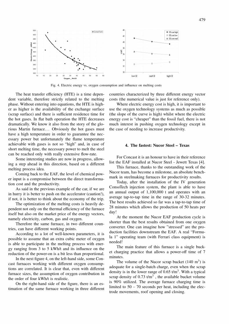
Fig. 4. Electric energy vs. oxygen consumption and influence on melting costs
The heat transfer efficiency (HTE) is a time depen-
dent variable, therefore strictly related to the melting
phase. Without entering into equations, the HTE is high-
er as higher is the availability of the exchange surface
(scrap surface) and there is sufficient residence time for
the hot gases. In flat bath operation the HTE decreases
dramatically. We know it also from the story of the glo-
rious Martin furnace. . . Obviously the hot gases must
have a high temperature in order to guarantee the nec-
essary power but unfortunately the flame temperature
achievable with gases is not so “high” and, in case of
short melting time, the necessary power to melt the steel
can be reached only with really extensive flow-rate.
Some interesting studies are now in progress, allow-
ing a step ahead in this direction, based on a different
melting process idea.
Coming back to the EAF, the level of chemical pow-
er input is a compromise between the direct transforma-
tion cost and the productivity.
As said in the previous example of the car, if we are
in hurry it is better to push on the accelerator (caution!),
if not, it is better to think about the economy of the trip.
The optimization of the melting costs is heavily de-
pendent not only on the thermal efficiency of the furnace
itself but also on the market price of the energy vectors,
namely electricity, carbon, gas and oxygen.
Therefore the same furnace, in two different coun-
tries, can have different working points.
According to a lot of well-known parameters, it is
possible to assume that an extra cubic meter of oxygen
is able to participate in the melting process with ener-
gy ranging from 3 to 5 kWh/t and its influence on the
reduction of the power-on is a bit less than proportional.
In the next figure 4, on the left-hand side, some Con-
cast furnaces working with different oxygen consump-
tions are correlated. It is clear that, even with different
furnace sizes, the assumption of oxygen contribution in
the order of four kWh/t is realistic.
On the right-hand side of the figure, there is an es-
timation of the same furnace working in three different
countries characterized by three different energy vector
costs (the numerical value is just for reference only).
Where electric energy cost is high, it is important to
use the oxygen technology systems as much as possible
(the slope of the curve is high) whilst where the electric
energy cost is “cheaper” than the fossil fuel, there is not
much interest in pushing oxygen technology except in
the case of needing to increase productivity.
4. The fastest: Nucor Steel – Texas
For Concast it is an honour to have in their reference
list the EAF installed at Nucor Steel - Jewett Texas [4].
This furnace, thanks to the outstanding work of the
Nucor team, has become a milestone, an absolute bench-
mark in steelmaking furnaces for productivity results.
Today, after the installation of the IV generation
ConsoTech injection system, the plant is able to have
an annual output of 1,100,000 t and operates with an
average tap-to-tap time in the range of 30-32 minutes.
The best results achieved so far was a tap-to-tap time of
28 minutes which allows the production of 50 heats per
day!
At the moment the Nucor EAF production cycle is
shorter than the best results obtained from one oxygen
converter. One can imagine how ”stressed” are the pro-
duction facilities downstream the EAF. A real “Formu-
la 1” operating team (with Ferrari class equipment) is
needed!
The main feature of this furnace is a single buck-
et charging practice that allows a power-off time of 7
minutes.
The volume of the Nucor scrap bucket (140 m3) is
adequate for a single-batch charge, even when the scrap
density is in the lower range of 0.65 t/m3. With a typical
scrap density of 0.73 t/m3 , the available bucket volume
is 90% utilized. The average furnace charging time is
limited to 50 – 70 seconds per heat, including the elec-
trode movements, roof opening and closing.
480
Each injector can work as a standard oxy-fuel burn-
er (5 MW), post-combustion injector (1000 Nm3/h) and
supersonic lance (2500 Nm3/h).
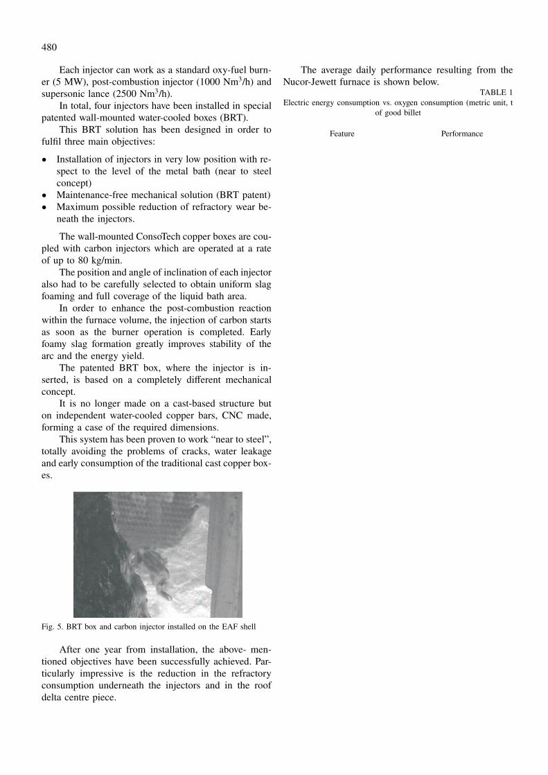
In total, four injectors have been installed in special
patented wall-mounted water-cooled boxes (BRT).
This BRT solution has been designed in order to
fulfil three main objectives:
• Installation of injectors in very low position with re-
spect to the level of the metal bath (near to steel
concept)
• Maintenance-free mechanical solution (BRT patent)
• Maximum possible reduction of refractory wear be-
neath the injectors.
The wall-mounted ConsoTech copper boxes are cou-
pled with carbon injectors which are operated at a rate
of up to 80 kg/min.
The position and angle of inclination of each injector
also had to be carefully selected to obtain uniform slag
foaming and full coverage of the liquid bath area.
In order to enhance the post-combustion reaction
within the furnace volume, the injection of carbon starts
as soon as the burner operation is completed. Early
foamy slag formation greatly improves stability of the
arc and the energy yield.
The patented BRT box, where the injector is in-
serted, is based on a completely different mechanical
concept.
It is no longer made on a cast-based structure but
on independent water-cooled copper bars, CNC made,
forming a case of the required dimensions.
This system has been proven to work “near to steel”,
totally avoiding the problems of cracks, water leakage
and early consumption of the traditional cast copper box-
es.
Fig. 5. BRT box and carbon injector installed on the EAF shell
After one year from installation, the above- men-
tioned objectives have been successfully achieved. Par-
ticularly impressive is the reduction in the refractory
consumption underneath the injectors and in the roof
delta centre piece.
The average daily performance resulting from the
Nucor-Jewett furnace is shown below.TABLE 1
Electric energy consumption vs. oxygen consumption (metric unit, t
of good billet
Feature Performance
Tapping capacity 82 t Power-on time 24 min
Shell diameter 6700 mm Power-off time 8 min
Shell volume 140 m3 Tap-to-tap time 32 min
Height of WC
panels 3100 mm Heats per day 45
Hot heel weight 25-35 t Productivity 150 t/h
Transformer 110 MVA Energy 380 kWh/t
Reactor On-line at 1640C
2.5 Ω/phase Natural gas 4.8 Nm3/t
Injectors 4 Oxygen 30 Nm3/t
Burner mode 5 MW C−−fine 14 kg/t
Lance mode 2500 Nm3/h Electrode 1.5 kg/t
5. The Benchmark: Icdas #1 – Turkey
For Concast, the furnace supplied to Icdas Biga steel
plant in Turkey [5], located on the Marmara sea, was the
first UHCP EAF but also quickly become a milestone in
the UHCP furnace design concept.
The close cooperation with the exceptionally-skilled
and determined Icdas team was essential to get a top
scoring EAF.
The sheer size of the “Biga#1 EAF”, 175 t tapping
capacity, the power input necessary to achieve its high
levels of performance (168 MVA transformer power,
21,000 Nm3/h O2 and 39 MW CH4 power) and the full
integration of the off-gas system with a scrap pre-heater,
have required innovative solutions in design, construc-
tion and operation of the furnace.
A summary of the Icdas yearly average EAF perfor-
mance, measured on good billets, shows:TABLE 2
Summary of the Icdas Biga #1 furnace
Productivity 230 t/h
Tap-to-tap 47 min
Electric energy consumption 290 kWh/t with hot scrap
Electric energy consumption 325 kWh/t with cold scrap
Total oxygen consumption 47 Nm3/t
Total natural gas consumption 6 Nm3/t
Electrode consumption 0.9 kg/t
performing a yearly production of 1,650,000 t with
one EAF only!
After three years of success and really outstanding
performance, the Icdas group decided to build a parallel
481
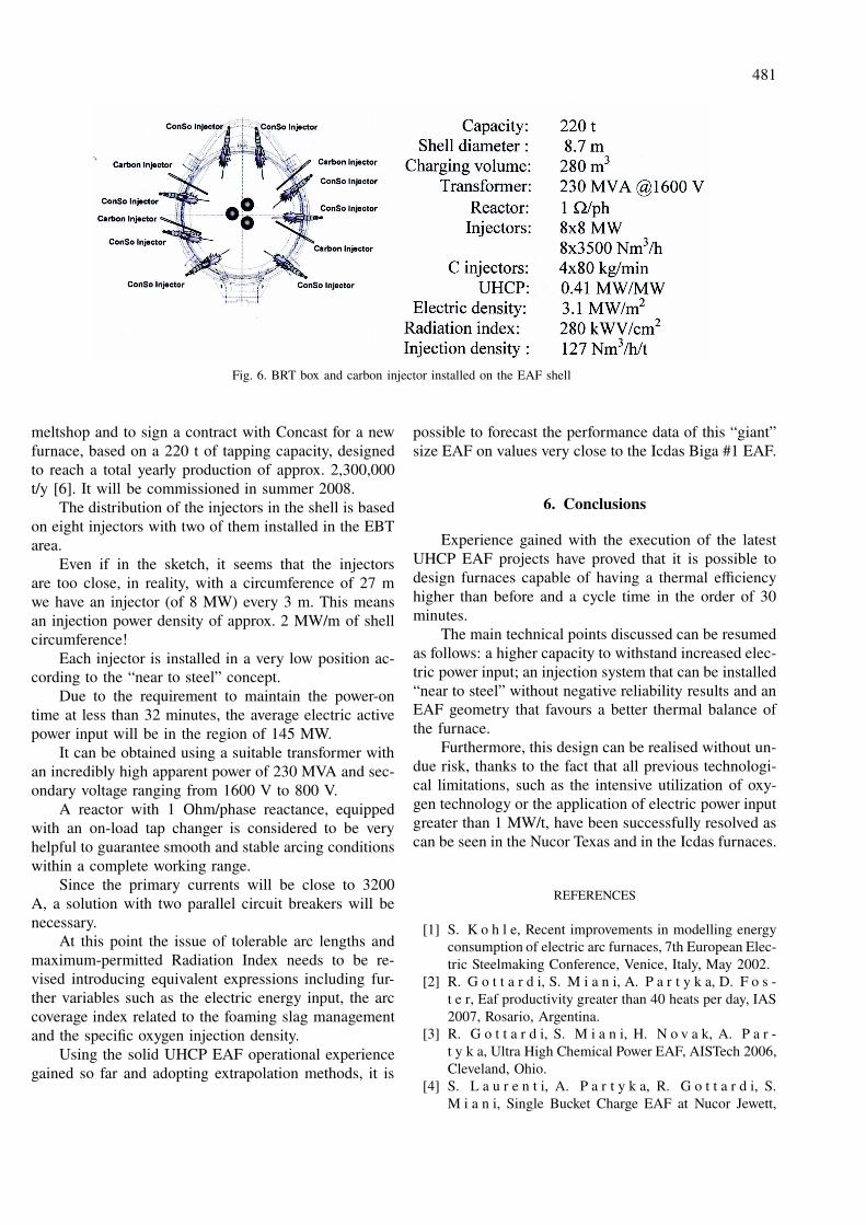
Fig. 6. BRT box and carbon injector installed on the EAF shell
meltshop and to sign a contract with Concast for a new
furnace, based on a 220 t of tapping capacity, designed
to reach a total yearly production of approx. 2,300,000
t/y [6]. It will be commissioned in summer 2008.
The distribution of the injectors in the shell is based
on eight injectors with two of them installed in the EBT
area.
Even if in the sketch, it seems that the injectors
are too close, in reality, with a circumference of 27 m
we have an injector (of 8 MW) every 3 m. This means
an injection power density of approx. 2 MW/m of shell
circumference!
Each injector is installed in a very low position ac-
cording to the “near to steel” concept.
Due to the requirement to maintain the power-on
time at less than 32 minutes, the average electric active
power input will be in the region of 145 MW.
It can be obtained using a suitable transformer with
an incredibly high apparent power of 230 MVA and sec-
ondary voltage ranging from 1600 V to 800 V.
A reactor with 1 Ohm/phase reactance, equipped
with an on-load tap changer is considered to be very
helpful to guarantee smooth and stable arcing conditions
within a complete working range.
Since the primary currents will be close to 3200
A, a solution with two parallel circuit breakers will be
necessary.
At this point the issue of tolerable arc lengths and
maximum-permitted Radiation Index needs to be re-
vised introducing equivalent expressions including fur-
ther variables such as the electric energy input, the arc
coverage index related to the foaming slag management
and the specific oxygen injection density.
Using the solid UHCP EAF operational experience
gained so far and adopting extrapolation methods, it is
possible to forecast the performance data of this “giant”
size EAF on values very close to the Icdas Biga #1 EAF.
6. Conclusions
Experience gained with the execution of the latest
UHCP EAF projects have proved that it is possible to
design furnaces capable of having a thermal efficiency
higher than before and a cycle time in the order of 30
minutes.
The main technical points discussed can be resumed
as follows: a higher capacity to withstand increased elec-
tric power input; an injection system that can be installed
“near to steel” without negative reliability results and an
EAF geometry that favours a better thermal balance of
the furnace.
Furthermore, this design can be realised without un-
due risk, thanks to the fact that all previous technologi-
cal limitations, such as the intensive utilization of oxy-
gen technology or the application of electric power input
greater than 1 MW/t, have been successfully resolved as
can be seen in the Nucor Texas and in the Icdas furnaces.
REFERENCES
[1] S. K o h l e, Recent improvements in modelling energy
consumption of electric arc furnaces, 7th European Elec-
tric Steelmaking Conference, Venice, Italy, May 2002.
[2] R. G o t t a r d i, S. M i a n i, A. P a r t y k a, D. F o s -
t e r, Eaf productivity greater than 40 heats per day, IAS
2007, Rosario, Argentina.
[3] R. G o t t a r d i, S. M i a n i, H. N o v a k, A. P a r -
t y k a, Ultra High Chemical Power EAF, AISTech 2006,
Cleveland, Ohio.
[4] S. L a u r e n t i, A. P a r t y k a, R. G o t t a r d i, S.
M i a n i, Single Bucket Charge EAF at Nucor Jewett,

482
Texas 8th European Electric Steelmaking Conference,
Birmingham, May 2005.
[5] A. P a r t y k a, R. G o t t a r d i, S. M i a n i, New giant
generation EAF, AISTech 2007, Indianapolis, USA.
[6] A. P a r t y k a, R. G o t t a r d i, S. M i a n i, B. E n -
g i n, UHCP for 320 t/h, ATS 2007, Paris, France.
Received: 2 April 2008.